1. Introduction
It has been recently noted from several authors [
1,
2] that the Leonardo da Vinci science is very close to the current Systems Science theory. Moreover, many aspects of the Leonardo way of thinking are in accordance with the paradigm of Complex Systems, especially with respect to the well known quote by R. Buckminster Fuller: Act locally, think globally [
3].
The paradigm of the Leonardo da Vinci studies have a lot of common points with the concept explained by Klaus Mainzer in [
4]. Indeed, the book “Thinking in Complexity”outlined the main guidelines for complexity proceeding from the classical system theory towards the new science of Complex Systems. In [
4], in fact, it is stressed that the general methods for controlling complex systems must rely over different sciences. Leonardo da Vinci followed a very similar approach during his life, focusing on several aspects from mechanics to hydraulic and biology. He can be, therefore, considered as one of the fathers of Complex Systems Engineering. Moreover, his contribution in defining the concepts of Mechanisms and Machines Engineering are still today fundamental for industrial engineering [
5].
This paper has two main aims. On the one hand, it aims at introducing a new perspective on Leonardo da Vinci machines and projects, highlighting the modernity of their working principles and the fact that their design is already oriented to a modern control approach. The classic mechanical technology adopted by Leonardo, therefore, straightforwardly joints with low-cost emergent information technologies, by using simple microcontrollers and telecommunication devices [
6], thus proving how a complete set of Leonardo machines can be controlled both locally and remotely. On the other hand, the paper provides simple and effective projects, which can be adopted in today’s machine dynamics lab to introduce students to basic automatic control problems and advanced solutions.
The educational projects in control engineering are fundamental topics today. With this in mind, it is important to link the Leonardo da Vinci concepts of engineer discipline with the new technologies of electronics and informatics. In the proposed projects, the use of Leonardo machines allows for understanding the principles of automatic control and applied mechanics through the realization of mechanisms and complex machines by using self-made elements.
In the history of Leonardo studies, the major relevance to his machines was given to the following classes of complex apparatii: war machines, like the robot soldier, the animal mechanical machines, like the bird and the lion, the self-propelling carts, the automata and the robots. In this paper, the attention has been focused on selected machines covering different mechanical, physical, music, and hydraulic disciplines. The various solutions adopted for the equipment implementation stress that the Leonardo’s designs give the possibility to follow different approaches for their realization [
7].
Indeed, the energy management and its control represents a cumbersome in modern engineer and in this direction the people has been addressed to approach the control problems. Moreover, the Leonardo da Vinci machines reflect the problem of energy. This aspect is today stimulating in order to address the new generations towards the well-known, but highly actual trend of using natural energy sources. The Leonardo machines are mainly based on spring motors actuated by humans, animals, hydraulic, or aeolic energy: in this study, such motor has been substituted by modern electric motor but maintaining the original working principles.
Moreover, another problem is the control of such a type of devices. The idea of educational projects in control engineering is to focus the interest of young generation in considering the engineering history and what has successfully adopted in the past to evaluate innovative strategies by using actual technology and to project the mind in the future.
The paper, contributing at marking the anniversary of Leonardo passing, has been inspired by several installations and exhibitions on Leonardo machines, in order to join the mechanical aspects with a complete view on automation and control systems to include modern technology. The history must be taken into account to be visionary but concrete. This is the added-value for both innovative visionary research and a sustainable engineer education.
The paper is organized as follows: in
Section 2, a set of composite machines are studied, focusing on the possibility of making them autonomous, both from the energy and from the performed actions points of view. Firstly, the selected Leonardo machines will be shortly described and then the automatic control equipment in order to provide them a specific innovation will be discussed. For each machine, the scheme of the added mechanisms is described, providing suggestions on how to replicate the proposed setups. Furthermore, the electronic devices included to control the machine behavior are described. In
Section 3, the automated Leonardo’s Flying Machine is described and the realized demo is shown. A brief discussion of some key aspects deriving from the proposed results are given in
Section 4, while conclusions are drawn in
Section 5.
2. Automated Machines
In this section, some selected Leonardo da Vinci machines will be reviewed, providing information on their implementation and automation, taking into account the knowledge of electronics and control systems. The machines are chosen ranging from the field of time measurement, motion transfer, music, hydraulics, and mechanics. The original models conceived by Leonardo da Vinci are realized following the guidelines of his projects by using mainly wood and light plastic materials. The following machines have been analyzed and automated, preserving their original working principles:
Drop Propagation
Mechanical clock
Lever Crane
Rolling ball timer
Transforming Motion
Mechanical Drum
Self-supporting bridge
In the following, details on the implementation of the model and the related automation and control systems are reported. Software details and microcontroller setups, together with videos showing the working automated machines, can be retrieved as Supplementary Material [
8].
2.1. Drop Propagation
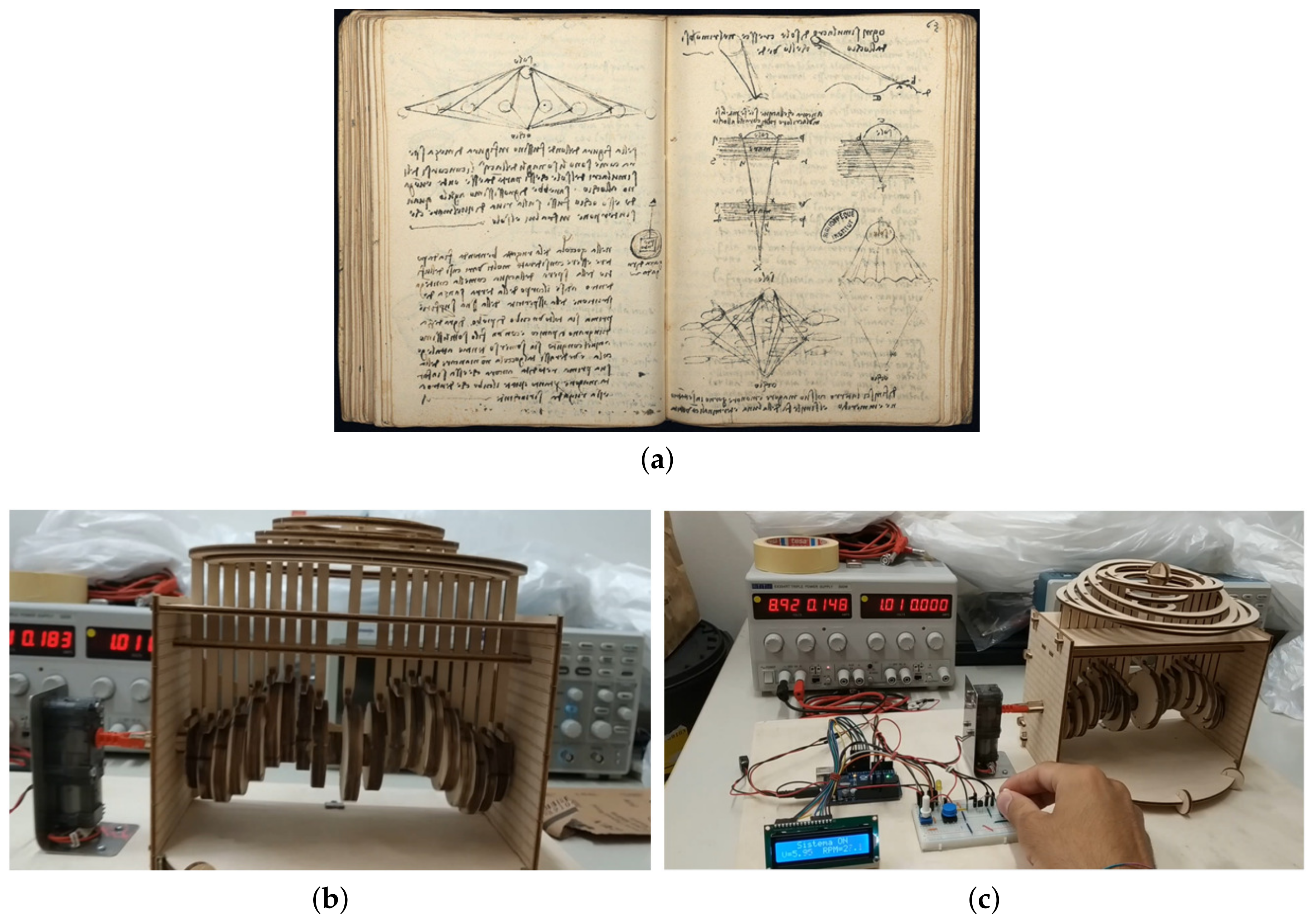
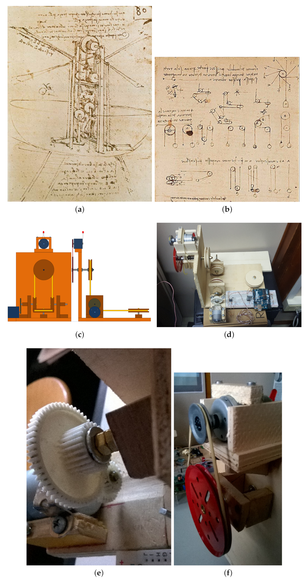
The first machine that will be analyzed is a machine able to simulate the wave propagation in a fluid when a drop hits its surface [
9]. Actually, this machine is not based on a Leonardo da Vinci drawing, but on several studies on hydraulics and wave propagation performed by Leonardo (Leonardo’s Codex Leicester
Figure 1a) [
10]. Starting from the Leonardo’s study, an automaton has been realized (
Figure 1b). This machine simulates in a synthetic but emphasized and spectacular way one of the simplest manifestations of nature, i.e., the drop falling on still water. The ripples of the surface of the water that are produced, for example, when a drop of rain falls into a puddle are two-dimensional waves: from the shape of their wavefronts, they are called circular waves.
No one before Leonardo da Vinci had tried to describe this phenomenon with the degree of detail comparable to the infinite motions of water, the interactions with other elements, and the continuous modifications produced on the surface. Still today, modeling fluids and, especially, microfluidic dynamics is an open problem [
11,
12,
13].
The automaton can be decomposed into four main components: the supporting structure, the camshaft, the piston rods, and the concentric rings. The structure is made with plywood panels to support the camshaft, which must rotate inside it, and by means of two overlapping panels spaced by a few centimeters, aligns the connecting rods, whose head pushes the numerous rings present above this structure. The camshaft represents the heart of this automaton. Equipped with an axial symmetry, it interacts directly with the gear motor transforming the rotation of its axis into the kinematics of the connecting rods. It consists of a series of carefully dimensioned and positioned shoulders that allow the creation of an extraordinary visual effect that simulates the propagation of circular waves whose wavelength is set by the construction of this component. Let us note from
Figure 1b how the head of the central pole is larger than those present at the sides and how they gradually get smaller and smaller, simulating a viscous damping of a weak type. Another thing to highlight (
Figure 1b) is how the wavelength is determined by the two bellies fixed by construction at a constant distance.
The piston rods are the most difficult components to implement (
Figure 1c). These connecting rods have the task of transforming the rotary motion of the camshaft in the oscillatory motion. In spite of their intuitive operation, they are not of immediate implementation, due to their continuous synchronous movement and the numerous frictions to which they are subjected during operation. There are 19 piston rods in total and it is sufficient that one of them does not slide, either because of the camshaft or because of the structure that held them in axis, so that it would cause the immediate blockage of the global kinematics.
The concentric rings are placed on pairs of connecting rods, placed at the same distance from the centre. They represent the circular wave and their oscillation dictated by the joint kinematics of camshaft and connecting rods, simulating the propagation of the wave.
As we can see in
Figure 1c, the cam shaft is actuated by a DC motor with a reduction mechanism to increase the torque. The automation solution envisaged for this project consists in the realization of a complete system of control and management of the camshaft rotation, based on the Arduino UNO microcontroller (
Figure 1c).
Using a transistor NPN BC547, it is possible to vary the voltage supplied to the motor thus changing its speed. A diode 1N4007 is connected in parallel to the power terminals of the gear motor in order to avoid dangerous voltage transients or spikes that can cause the pilot transistor rupture. A 10 k potentiometer has been used to adjust the speed and to provide the control board the reference of 5 V. The speed is measured by the analog input of the microcontroller, so as to manage the output voltage at the pin PWM5. The use of a button normally open, with a pull-down resistance of 100 k, allows for start and stop the operation of the model. To complete the user interface of the entire automation system, there is an LCD1602 display connected with the microcontroller, which visualizes the status of the system, the value of the voltage sent to the gear motor and the corresponding value of RPM.
The realized hardware and the developed software allow for acquiring the frequency of the wave according to the supply voltage of the gear motor. This frequency is related to the different body that impact with the body of the water. It is possible to implement on this setup a feed forward control that relates the frequency of the wave with the DC motor velocity through Arduino.
2.2. Mechanical Clock
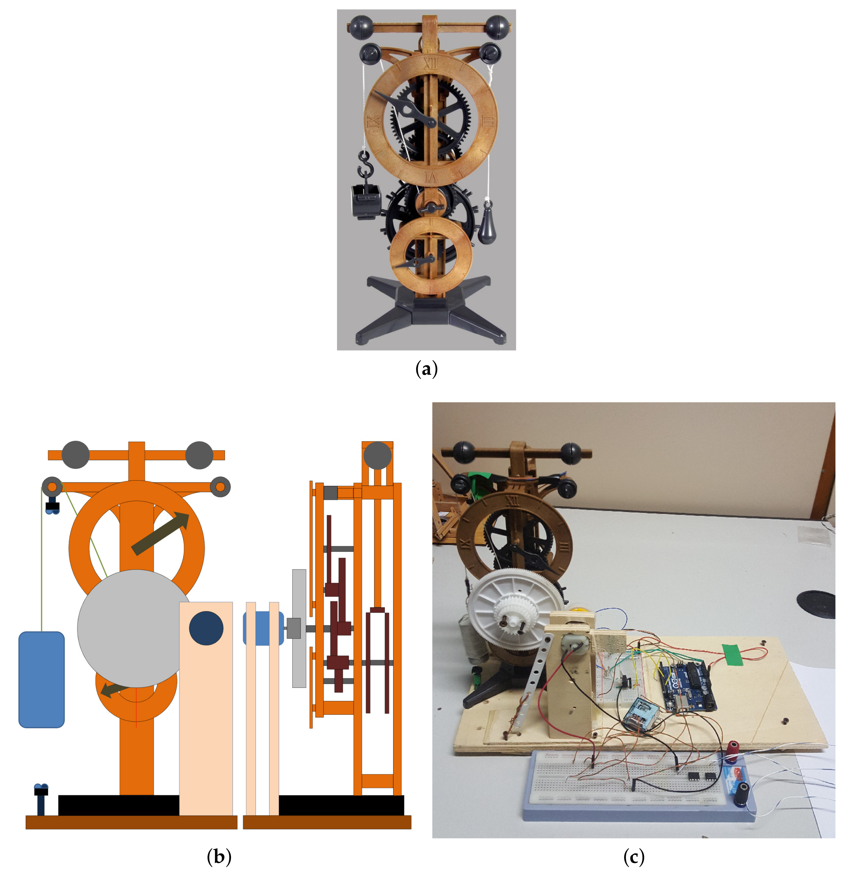
The second machine analyzed is the mechanical clock, whose original model by Leonardo is reported in
Figure 2a. Leonardo used an iron based spring system to get the clock charge and a weight system in order to balance the clock. The spring system is discharged by means of an applied weight and actuate the two swinging weights on top of the clock, thus enabling the clock motion. When the weight reaches the basement of the clock, the spring needs to be mechanically recharged.
Mechanical clocks have been controlled using feedback to control the speed of the devices [
14]. Here, even if the mechanical timing system of Leonardo has been maintained, the innovated project consists of including an intelligent device to recharge the clock when the weight reaches its lowest position. To accomplish such a task, opportunely located sensors [
15] and an actuation system are necessary. Moreover, a microcontroller can be included to drive the charge process.
As concerns the sensing system, a pair of reflective optical sensor with transistor output has been adopted, namely the TCRT5000 produced by Vishay Semiconductors, Malvern, PA, USA. This device is very compact in size (L × W × H in mm: ), robust in operation and, in the same package, contains the infrared photodiode emitter and the detector phototransistor. The latter is provided with filter block for the ambient light in the visible. Through these sensors, it is possible to determine the position of the discharging weight.
As concerns the actuation, a fundamental problem is providing a torque sufficient to charge the spring. The torque supplied by a standard 3V DC motor is not sufficient to this task; therefore, a suitable gear system must be designed [
16]. On the motor shaft, a gear of 16mm diameter is spliced. Such gear contacts a larger gear, with 87 mm diameter, in order to multiply the torque, which is directly spliced on the circular spring allowing for clock charge. The actuation is governed by an Arduino microcontroller, which is interfaced with a relay to deactivate the motor during the clock operations.
The schematic of the innovated machine is reported in
Figure 2b, while a picture of the automated clock is reported in
Figure 2c.
2.3. Lever Crane
Another machine that has been analyzed is one of the simplest cranes [
17], the Lever Crane that was realized thanks to the Leonardo’s design, originally conceived for a system able to lift a weight. The lever crane system uses a ratchet mechanism that rotates in one direction to lift a weight with a fraction of the strength of a simple pulley. The original sketches are included in
Figure 3a.
The automatic model of the lever crane is designed in order to provide a continuous motion lifting and lowering the weight. Switching between the two directions is ensured by means of small push buttons located at the end of run of the lever. Actuation is obtained equipping the model with a servo-motor spliced with a gear which contacts a larger gear located on the crane axis to ensure the desired torque. The schematic representation of the automated lever crane can be retrieved in
Figure 3b. Moreover, an Arduino board controls the motion reacting to an external input provided through a Bluetooth module HC-05. This example introduces the possibility to remotely control the actuation of the lever crane, therefore bypassing the two push buttons. Standard smartphones or tablets can be used to link the microcontroller through the Bluetooth module. The complete setup is shown in
Figure 3c.
2.4. Rolling Ball Timer
The idea of building clock based systems, and therefore intelligent systems, was recurrent in the Leonardo da Vinci mind. The time concept focused the Leonardo da Vinci attention on another exhaustive example: the rolling ball timer. It was conceived to be able to measure different time intervals on the basis of the weight of the rolling ball. The machine is based on a sketch of an escapement mechanism drawn by Leonardo da Vinci. The system is based on exploiting the principle of gravity as a kinetics to measure the flowing of the time. The realization of the rolling ball timer is based on the model reported in
Figure 4a.
The working principle is based on a lever supporting a weight, which falls down each time the rolling ball completes his path. The ball then mechanically actuates a rod which inverts the balance of the board and makes the ball rolling backward. Similarly to the mechanical clock, an actuation able to bring the lever up to the highest position when it reaches the lowest point is needed to allow for a continuous flow of temporal intervals. The automation is realized through a DC motor shafted to a gear of 25 mm which contacts a larger gear with a diameter of 70 mm, solving the problem of the needed torque. This latter gear is coaxial with a bullwheel over which a rope is wrapped. The rope is linked to the timer lever. When the lever reaches the lowest position, it hits a switch driving the Arduino board. An electromagnetic actuator ensures that the rods are not blocking the board while the lever reaches the upper position. The complete innovated model is reported in
Figure 4b.
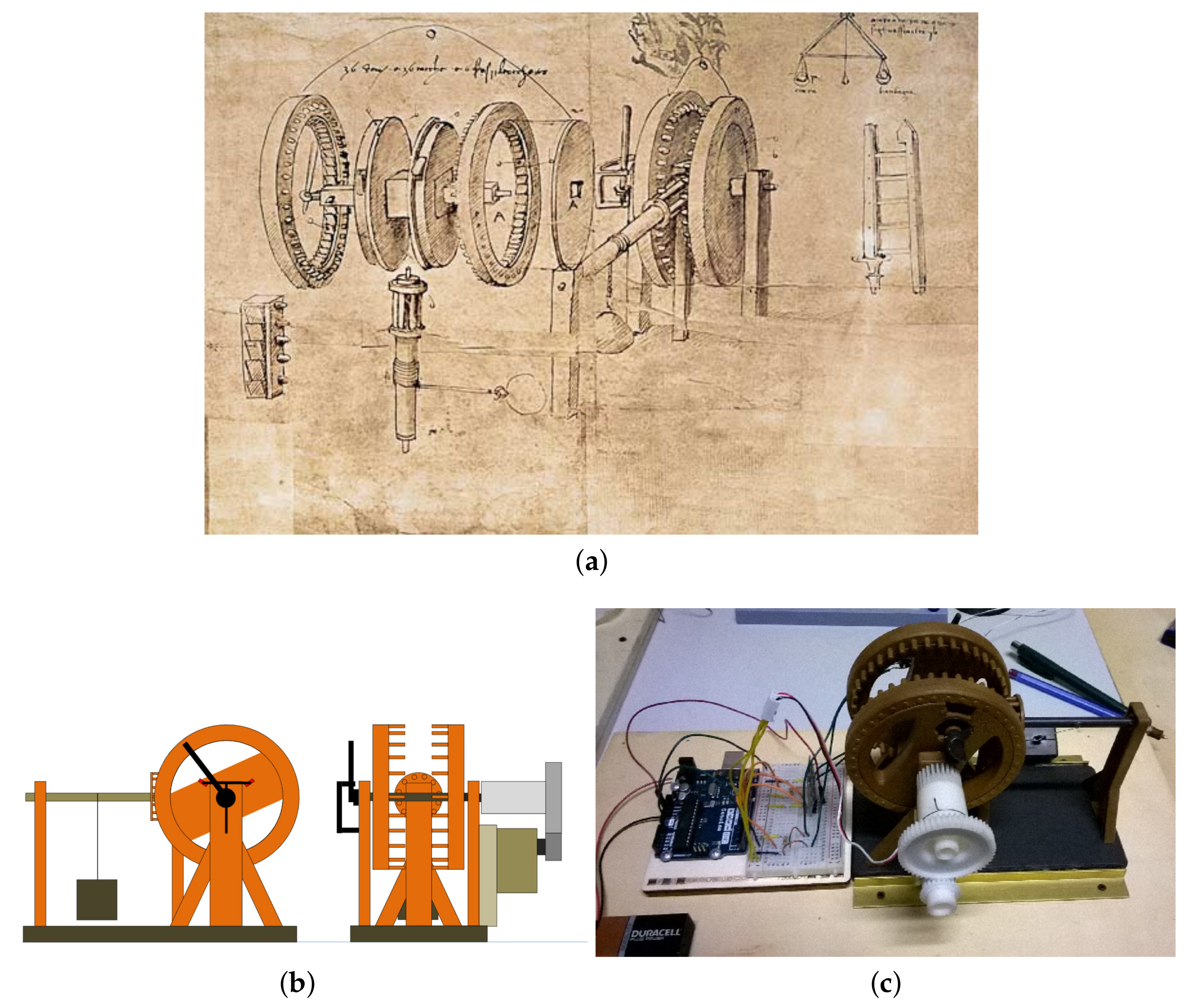
2.5. Motion Transformation
Considering the limited number and the related efficiency of the available source of energy at his times, Leonardo proposed several strategies to transform and transfer a rotation parallel to the ground, such that was impressed by an ox carrying a lever connected to a wheel, to a rotation orthogonal to the ground, such that was needed to lift or lower a weight. Moreover, his idea provides the possibility to transfer the motion on different levels and altitudes and remarks the reversibility of prime motors that could be used both as actuators and as energy sources. This concept is intrinsic in the Leonardo da Vinci way of thinking, and it is intrinsically shown by the proposed equipment.
His studies led to different solutions, either based on gears, as in
Figure 5a or on bullwheels and ropes, as in the drawings in
Figure 5b. In this paper, a completely autonomous system of bullwheels able to transfer the energy has been realized. In the schematic representation reported in
Figure 5c, two motors considered, located in separate positions. One motor is used as an actuator, impressing to the wheel the motion, and it is controlled via Bluetooth. The second motor is used as dynamo to provide energy to a led: the conversion to the electrical energy via the dynamo represents a simple and effective way to show that the motion is transformed towards a different axis.
The realized model is shown in
Figure 5d. In particular, the shaft of the actuated motor is spliced to a gear contacting a larger gear joint with a bullwheel [
18], again with the purpose of increasing the torque. An elastic rope allows for the rotation of the other bullwheels, in particular of one joint with a further larger one. From this bullwheel, motion is transferred to the DC motor acting as dynamo (
Figure 5e,f). The whole system is controlled through a smartphone linked to the bluetooth device installed on the microcontroller.
2.6. Mechanical Drum
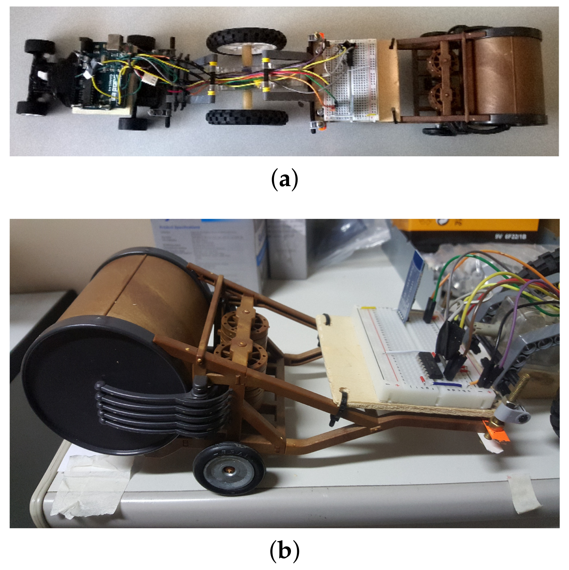
Leonardo also proposed a set of machines finalized to music. One of these, the mechanical drum, is reported in a sketch of Codex Atlanticus, Folio 837 and it was conceived by Leonardo da Vinci as an entertainment machine in the courts. When pulled or started by a handle, the gears rotate the two side of the drum which is equipped with pegs. These pegs, which can be placed in various positions, move their sticks beating a large drum. The changing position of the pegs alters the rhythm of the music.
The innovated mechanical drum includes some driving equipment electrically controlled with autonomous power supply and a remote controller. The model with the control setup is reported in
Figure 6. It consists of a wheeled cart supporting the control, the actuation and the power supply devices, linked with the mechanical drum. For the actuation system, we adopted a DC motor with multiple reduction gears in order to provide the wheels with the torque necessary to overcome friction and start moving and playing the drum. Moreover, a servomotor is used to deflect two coordinated wheels in order to allow turnings. The model is remotely controlled by using a bluetooth device linked to a smartphone.
2.7. Self-Sustaining Bridge
The last machine analyzed in this section is the bridge. Leonardo designed this bridge under the patronage of Cesare Borgia. The design of this project is included in the Codex Atlanticus, Folii 69 AR, 71 V. The sketch of the Leonardo design is reported in
Figure 7a. It requires no nails or ropes to hold it together, as the bridge is self-supporting. The Leonardo bridge is realized by using wood elements as shown in
Figure 7b.
Differently from the other machines, the self-sustaining bridge is not automated, but it is proposed as an experimental platform for dynamic vibrational studies [
19]. The ease of building bridges by following the Leonardo design may contrast with essential specifications on reliability and robustness.
In order to provide a vertical oscillation soliciting the structure, an electromagnet has been placed on a bridge. The frequency and the amplitude of the oscillation can been varied using a signal generator inducing a current in the coil of the electromagnet. An experimental evaluation of the frequency response of the self-supporting bridge can be thus easily retrieved if a frequency sweeping signal is provided to the electromagnet.
Interestingly, the model of the Leonardo bridge proved to be highly robust to a wide range of low and high frequency, while it tends to disassemble when solicited with a frequency around 10 Hz, thus representing the resonance frequency of the realized structure.
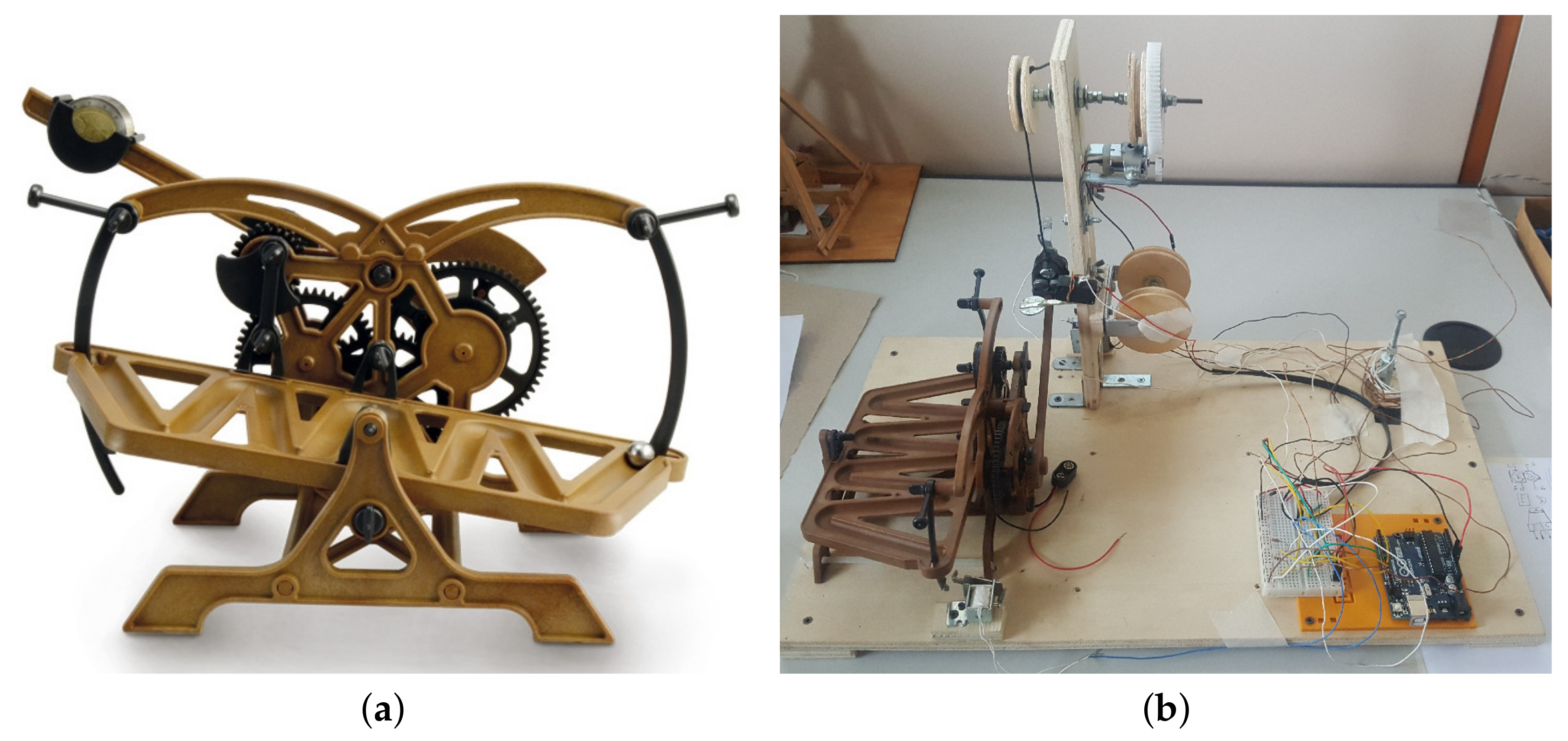
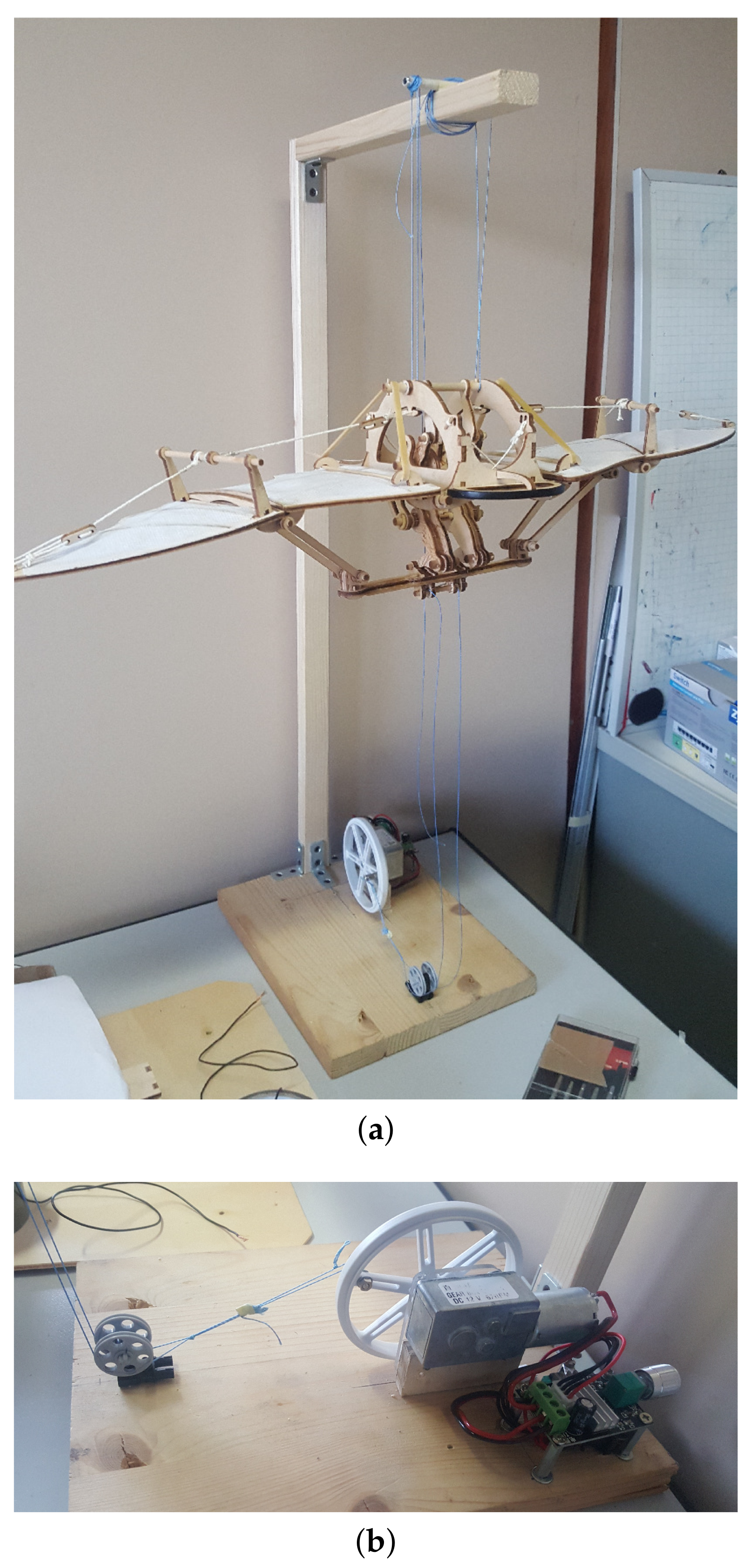
3. Flying Machine
The Leonardo flying machine can be considered as the introduction of the machinery in the history of flying. In
Figure 8, two pictures of the Leonardo flying machine model realized are reported.
The main studies of da Vinci about the flight are included in the Codex on the flight of the birds. It is a short codex dated 1505 containing 18 folios. The codex is now located in the Museum of the Biblioteca Reale in Turin. In this codex, Leonardo investigates and explains some particular physical aspects related to the mechanics of flight. He discusses on the gravity, on the density of the air, on the concept of force balance, and also on oscillations. By deeply studying the anatomy of birds wings, Leonardo understood that the flight of birds depends on the air fluid dynamics but more effectively on the ability of the birds of self-adapting to the air flows, thus maximizing the efficiency of the flight. Leonardo further analyzed the bird dynamics observing the soaring dynamic obtained without flapping their wings. Without a well established aerodynamic theory, he understood that the bird has a natural ability to adjust itself to remain in the air. The wall of wind transfers some of its kinetic energy to the bird, but it is essentially unaffected by the interaction. In actual soaring flight, much or all of the bird’s kinetic energy gain is dissipated by drag forces, so the flight is energy neutral.
A demo model realized in wood from the design of Leonardo flying machine has been used. We included in the automated version of the flying machine a high torque 12V DC motor linked to an endless screw providing 62RPM, controlled by a PWM speed controller able to reverse the rotation direction. The motor actuates a rotating gear which is linked in an eccentric position to a rope. Motion is transferred by the means of two bullwheels around which the rope is located to the base of the flying machine which is moved upward and downward alternatively, thus impressing the motion to the machine wings. The automated setup, which has presented as a simple demo of the operating flying machine, is reported in
Figure 9. The effect of motion is here reproduced comparing the still flying machine in
Figure 10a with the picture taken by using a long exposure camera reported in
Figure 10b.
4. Discussion
It is our opinion that many of Leonardo da Vinci machines projects were conceived in a modern way and with a modern aim: transforming and transferring energy [
20]. The main limitation of his machines, in fact, stands in the fact that the sources of energy at his time were few. The electric power machines did not exist. Only human power, animal power, hydraulic, and wind energy do appear useful in real life.
Then, the idea of saving energy for future reuse arose in his mind. Moreover, the unique autonomous motor that Leonardo could use in the design of his autonomous machines and robots was the spring based motor. Leonardo da Vinci had the concept of saving energy into the spring clear in mind and, therefore, he knew how to use the elastic principle to save energy.
This concept is linked to the idea of force that Leonardo foresaw, something able to affect the object in such a way that it is possible to impress rest or motion. Therefore, before Galileo and Newton, Leonardo practically conceived the principle of inertia in mechanics, relying, as he wrote, on a spiritual, incorporeal, and invisible power. Moreover, he was conceiving, with his protoscientific knowledge, the concepts of stability and equilibria thus anticipating milestones of automatic control and systems theory, such as equilibrium and stability.
The Leonardo da Vinci machines show that he had also achieved in his mind an ordered view of new disciplines: automatic control and applied mechanics. He drew several prototypes of chains and bearings establishing a rigorous approach to applied mechanics. He understood the importance of friction in designing its equipment and he was able to conceive the first mechanical bearing.
Moreover, in the Leonardo da Vinci machines conception, he assumed the perspective that the machines must be also considered as the element of a complex system that is a plant made by driving machines and operating machines.
As it has been proven, the Leonardo machines are designed in a modern way which allows for a direct automation and control preserving their key working principles. Moreover, the control of the wooden Leonardo machines, which include the imperfections related to that technology, can be performed thanks to the precise information technology devices, making what may appear hard for the wood technology, possible and reliable by using control techniques [
21].
Therefore, this paper paves the way for further research on the fact that imperfections or uncertainties can be successfully controlled if the original machines are well conceived, like the Leonardo machines, and where suitable control devices and algorithms are adopted. This can represent a novel paradigm to design mechanical devices, following the route traced by Leonardo five centuries ago.
5. Conclusions
The paper includes some results developed in the Control of Complex Systems Lab at the University of Catania, within an educational project developed in the master course of Automation Engineer of the University of Catania. The aim of the project was to link the past and the future and to emphasize the fundamental role of classical mechanics in engineering projects, proposing innovative solutions adopting low-cost equipment. The organization of interdisciplinary lab experiments based on Leonardo da Vinci machine’s model increases the interest of students in learning from history and applying ideas focusing on automation aspects.
This paper emphasizes a generic concept common to the design of all Leonardo machines, i.e., the flexibility of the Leonardo machines to be controlled by using ad-hoc modern control techniques and devices. We remark also that this contribution puts the Leonardo machines in the general context of the Internet of Things (IoT), since the automated machines are allowed to communicate through wireless technology, thus opening the way to the realization of interactive installations, joining classical mechanics of Leonardo with modern control technology. Moreover, the paper aims also at emphasizing that many Leonardo machines actually work thanks to the imperfections of the constructive process, and it is exploiting such imperfections that the machines can be controlled: an example is the motion transformation, whose working principle is strictly based on the friction between the bullwheels and the elastic rope emphasized by the irregularities of the wooden elements.
Moreover, the lab experiments had been developed looking at recycling and to the circular economy, also in the spirit of using electronic components. The collection of the realized machines belongs to the museum of the automation of complex system of the University of Catania. The project led also to new ideas in developing machines built with wood and controlled by electronic components in order to achieve a new discipline called woodtronics. The easy realization of structures based on recycled wood, coupled to reusable electronic components, motors and controlled equipment, and low-cost microcontrollers, allows for realizing safe laboratory activities and carrying out stimulating ideas in order to design and realize new machines leading, first of all, thinking.
The conception of the set of machines shown in this paper, together with other interactive robots [
22,
23], are part of a project finalized for rehabilitation-education purposes. This represents a further social impact of the Leonardo da Vinci contribution.
Author Contributions
Conceptualization, M.B., A.B., C.F., L.F. and S.G.; Data curation, C.F. and S.G.; Formal analysis, L.F.; Investigation, A.B., L.F. and S.G.; Methodology, M.B., A.B., L.F. and S.G.; Software, A.B., C.F.; Supervision, L.F.; Validation, M.B. and C.F.; Writing—original draft, M.B. and A.B.; Writing—review & editing, M.B., A.B., L.F. and S.G. All authors have read and agreed to the published version of the manuscript.
Funding
This research received no external funding.
Acknowledgments
The authors wish to thank the Centro Internazionale di Studi sul Barocco di Siracusa (director Lucia Trigilia), where the machines are exhibited today, and the anonymous Reviewers for their fundamental comments and observations.
Conflicts of Interest
The authors declare no conflict of interest.
References
- Kemp, M. Leonardo da Vinci; Oxford University Press: Oxford, UK, 2007. [Google Scholar]
- Taddei, M. I Robot di Leonardo; Leonardo: Milano, Italy, 2007. [Google Scholar]
- Fuller, R.B. Buckminster Fuller: Anthology for the New Millennium; Macmillan: New York, NY, USA, 2001. [Google Scholar]
- Mainzer, K. Thinking in Complexity: The Computational Dynamics of Matter, Mind, and Mankind; Springer Science & Business Media: Berlin/Heidelberg, Germany, 2007. [Google Scholar]
- Ceccarelli, M.; Carbone, G. Advances of Italian Machine Design. Machines 2019, 7, 61. [Google Scholar] [CrossRef] [Green Version]
- Barbon, G.; Margolis, M.; Palumbo, F.; Raimondi, F.; Weldin, N. Taking Arduino to the Internet of Things: The ASIP programming model. Comput. Commun. 2016, 89, 128–140. [Google Scholar] [CrossRef] [Green Version]
- Moon, F.C. The Machines of Leonardo Da Vinci and Franz Reuleaux: Kinematics of Machines From the Renaissance to the 20th Century; Springer Science & Business Media: Berlin/Heidelberg, Germany, 2007; Volume 2. [Google Scholar]
- Available online: https://studentiunict-my.sharepoint.com/:f:/g/personal/arturo_buscarino_unict_it/EjEP_1UHTNhIqi1lumz_kPUBTO27z_QY2l5i_gdd-yq-Ww?e=im60am (accessed on 3 September 2020).
- Roisman, I.V.; Tropea, C. Impact of a drop onto a wetted wall: Description of crown formation and propagation. J. Fluid Mech. 2002, 472, 373. [Google Scholar] [CrossRef]
- Macagno, E. Some remarkable experiments of Leonardo da Vinci. Houille Blanche 1991, 6, 463–471. [Google Scholar] [CrossRef] [Green Version]
- Monaghan, J.J.; Kajtar, J.B. Leonardo da Vinci’s turbulent tank in two dimensions. Eur. J. Mech. B Fluids 2014, 44, 1–9. [Google Scholar] [CrossRef]
- Cairone, F.; Gagliano, S.; Bucolo, M. Experimental study on the slug flow in a serpentine microchannel. Exp. Therm. Fluid Sci. 2016, 76, 34–44. [Google Scholar] [CrossRef]
- Sapuppo, F.; Llobera, A.; Schembri, F.; Intaglietta, M.; Cadarso, V.J.; Bucolo, M. A polymeric micro-optical interface for flow monitoring in biomicrofluidics. Biomicrofluidics 2010, 4, 024108. [Google Scholar] [CrossRef] [PubMed] [Green Version]
- Lepschy, A.M.; Mian, G.A.; Viaro, U. Feedback control in ancient water and mechanical clocks. IEEE Trans. Educ. 1992, 35, 3–10. [Google Scholar] [CrossRef]
- Webster, J.G. (Ed.) The Measurement, Instrumentation, and Sensors: Handbook; Springer Science & Business Media: Berlin/Heidelberg, Germany, 1999. [Google Scholar]
- Zhang, D.; Wei, B. Study on Payload Effects on the Joint Motion Accuracy of Serial Mechanical Mechanisms. Machines 2016, 4, 21. [Google Scholar] [CrossRef]
- Dickie, D.E. Crane Handbook; Butterworth-Heinemann: Oxford, UK, 2013. [Google Scholar]
- Grote, K.H.; Antonsson, E.K. (Eds.) Springer Handbook of Mechanical Engineering; Springer: Berlin/Heidelberg, Germany, 2009; Volume 10. [Google Scholar]
- Siami, A.; Cigada, A.; Karimi, H.R.; Zappa, E. Vibration Protection of a Famous Statue against Ambient and Earthquake Excitation Using A Tuned Inerter–Damper. Machines 2017, 5, 33. [Google Scholar] [CrossRef] [Green Version]
- Anvari-Moghaddam, A.; Mohammadi-Ivatloo, B.; Asadi, S.; Guldstrand Larsen, K.; Shahidehpour, M. (Eds.) Sustainable Energy Systems Planning, Integration and Management; MDPI Books: Basel, Switzerland, 2019. [Google Scholar]
- Bucolo, M.; Buscarino, A.; Famoso, C.; Fortuna, L.; Frasca, M. Control of imperfect dynamical systems. Nonlinear Dyn. 2019, 98, 2989–2999. [Google Scholar] [CrossRef]
- Buscarino, A.; Camerano, C.; Fortuna, L.; Frasca, M. Interactive Bubble Robots for Art: Movement Sequences Learning through Mirror Neurons. Ifac Proc. Vol. 2009, 42, 217–222. [Google Scholar] [CrossRef]
- Buscarino, A.; Camerano, C.; Fortuna, L.; Frasca, M. Chaotic mimic robots. Philos. Trans. R. Soc. Math. Phys. Eng. Sci. 2010, 368, 2179–2187. [Google Scholar] [CrossRef] [PubMed]
© 2020 by the authors. Licensee MDPI, Basel, Switzerland. This article is an open access article distributed under the terms and conditions of the Creative Commons Attribution (CC BY) license (http://creativecommons.org/licenses/by/4.0/).

 ,
, 


