Article

Experimental Study on the Influence of Machining Conditions on the Quality of Electrical Discharge Machined Surfaces of aluminum alloy Al5052

by
Angelos P. Markopoulos
1,*,
Emmanouil-Lazaros Papazoglou
1 and
Panagiotis Karmiris-Obratański
1,2
1
Laboratory of Manufacturing Technology, School of Mechanical Engineering, National Technical University of Athens, Heroon Polytechniou 9, 15780 Athens, Greece
2
School of Mechanical Engineering and Robotics, AGH University of Science and Technology, Mickiewicza 30, 30-059 Cracow, Poland
*
Author to whom correspondence should be addressed.
Machines 2020, 8(1), 12; https://doi.org/10.3390/machines8010012
Submission received: 20 January 2020 / Revised: 26 February 2020 / Accepted: 27 February 2020 / Published: 2 March 2020

Abstract

:
Although electrical discharge machining (EDM) is one of the first established non-conventional machining processes, it still finds many applications in the modern industry, due to its capability of machining any electrical conductive material in complex geometries with high dimensional accuracy. The current study presents an experimental investigation of ED machining aluminum alloy Al5052. A full-scale experimental work was carried out, with the pulse current and pulse-on time being the varying machining parameters. The polishing and etching of the perpendicular plane of the machined surfaces was followed by observations and measurements in optical microscope. The material removal rate (MRR), the surface roughness (SR), the average white layer thickness (AWLT), and the heat affected zone (HAZ) micro-hardness were calculated. Through znalysis of variance (ANOVA), conclusions were drawn about the influence of machining conditions on the EDM performances. Finally, semi empirical correlations of MRR and AWLT with the machining parameters were calculated and proposed.

Graphical Abstract

1. Introduction

Electrical discharge machining (EDM) is one of the most extensively used non-conventional machining processes, with many applications in the modern industrial environment. The main advantage of EDM is the capability of machining any electrical conductive material, regardless of its mechanical properties, e.g., strength and hardness, in complex geometries and with high dimensional accuracy. EDM finds a wide range of applications in the fields of die and mold manufacturing, aerospace, automotive industries, micro-electronics, and biomedical engineering [1]. EDM is a thermoelectric process, as the material erosion mechanism is the result of a series of discrete electrical discharges. These occur between the electrode and workpiece, which are immersed in a dielectric fluid [2]. The electrical energy turns into thermal, generating a plasma channel between the cathode and the anode. With plasma temperatures in the range of 8000 to 12,000 °C, the material is heated up to its melting and/or ablation point. When the pulsating current supply is turned off, the plasma channel breaks down, allowing the dielectric fluid to flush the molten and ablated material in the form of microscopic debris.
In contrast to the plethora of studies pertaining to EDM of steel workpieces, there are only a few works about machining aluminum and aluminum alloys. Keeping in mind that aluminum and its alloys are extensively used in the aerospace and automotive industry, and its use as a matrix in composite materials, it is, beyond the scientific interest, extremely useful to be studied as a workpiece material in EDM. Khan [3] studied and analyzed the wear of the electrode during EDM. Mild steel and aluminum were used as workpiece materials and copper and brass as the tool electrode. Among the conclusions was that during machining, the mild steel electrode undergoes more wear than in the machining aluminum. This is due to the higher thermal conductivity of aluminum that results in less energy dissipation to the electrode. Gatto et al. [4] verified the machinability of three aluminum alloys, namely Al2219 and Al7050, which are used in aeronautical applications, and Al7075, a common alloy for pre-series molds. Surface finish, dimensional and geometrical accuracy of the workpieces and the wear mechanism of the electrodes were evaluated. Radhika et al. [5] investigated the influence of pulse current (10–30 A), pulse on time (120–420 μs), and dielectric flushing pressure in EDM of aluminum hybrid composites by using the Taguchi method. The material removal rate (MRR), the tool wear ratio (TWR), and the surface roughness (SR) were calculated or measured. Imran et al. [6] studied the machining of Al6061 with EDM under a variety of pulse current (6–12 A) and pulse-on time (60–200 μs) conditions, using graphite electrode and two different dielectric mediums. MRR, TWR, surface integrity in terms of the average white layer thickness (AWLT), and the SR were calculated. Finally, Kandpal et al. [7] and Selvarajan et al. [8], through their review papers, show the increasing interest in machining metal matrix composites (MMC), including those with an aluminum matrix, with EDM.
The current study is an experimental investigation of the effect of machining parameters, namely the pulse current IP and the pulse on time Ton, on the machining of aluminum alloy Al5052 with EDM. The choice of the alloy is based on its properties, as it has very good corrosion resistance to seawater and industrial atmosphere, and is used for metal matrix composites fabrication. [9] Furthermore, the working conditions under EDM processing of this material have not been thoroughly investigated, yet. In the analysis, MRR is calculated, Ra and Rt are measured, as indications of the machined surface quality, and through microscopic observation, AWLT and White Layer (WL) morphology are estimated. Finally, after the experimental procedure, non-linear regression models are calculated and proposed, correlating the MRR and the AWLT with the machining parameters, namely, the pulse current and the pulse on time.

2. Experimental Procedure

An ANGIETRON EMT 1.10 die sinking machine was used for the experiments. The workpieces were two rectangular blocks of aluminum alloy Al5052, and on each face, in successive positions, four experiments were conducted. The chemical composition of Al5052 alloy and its physical properties are presented in Table 1. A rectangular copper electrode with dimensions of 38 × 23 mm was used as the working tool, which was properly cleaned between experiments to avoid any depositions that may affect the results. A rectangular copper electrode with dimensions of 38 × 23 mm was used as the working tool, and was cleaned properly between experiments to avoid any depositions that could affect the results. Finally, a low viscosity hydrocarbon mineral oil (Castrol SE FLUID 180) was used as the dielectric fluid. Its low viscosity ensured sufficient cooling and debris flushing, even for narrow spark gaps. This dielectric fluid is recommended for machining with EDM all ferrous and non-ferrous metals.
A full-scale experiment was carried out, with varying parameters, the pulse current IP and the pulse-on time Ton at four levels for each one. The 16 sets of the experiments’ parameters are analytically presented in Table 2. In all experiments, straight polarity was used, with 100 and 30 V as the open and close circuit voltage, respectively. Moreover, the dielectric fluid flushing pressure was constant for all the experiments, while the duty cycle was automatically adjusted by the machine, for optimized machining efficiency. The workpiece weight before and after machining, the total machining time, the ammeter indication of the mean current intensity ĪP, and the machining efficiency (feff) were transcribed for subsequent calculations, evaluation, and analysis. For a more accurate calculation of the real machining time tm, the “jumping cycles”, namely the periodic movement of the servo head for facilitating the debris removal during machining, were considered. Furthermore, the average and the maximum surface roughness Ra and Rt, respectively, were measured, calculated as the mean from five measurements made on each machined surface. For the values of the machined surfaces, the proper stylus tip, and the cut-off wavelengths were adopted according to EN ISO 4287:1998. Specifically, the stylus tip was 10 μm, and the shortest and longest cut-off wavelength was 2.5 and 8 mm respectively. The measuring system Mitutoyo SV-4500 CNC was used.
Finally, the machined surfaces in their perpendicular plane were grinded, polished, and chemically attacked with etchant, which was composited by 92 ml distilled water, 6 ml nitric acid and 2 ml hydrofluoric acid, and immersion of samples for 20 s in the bath. The etched surfaces were observed in optical microscope and the AWLT was calculated, while observations about the WL quality and morphology were made. The AWLT was calculated by dividing the area of the WL with its corresponding length. At the end, the micro-hardness of the material, just below the WL, was measured in order to establish the existence of a heat affected zone (HAZ). The micro-hardness was calculated as the mean from six measurements at each specimen using the Vickers hardness test.
The MRR was calculated by using Equation (1):
M R R = W s t W f i n ρ t m ,
with MRR the material removal rate in mm3/min, Wst., Wfin the workpiece weight before and after machining, respectively, in g, ρ the workpiece material density in g/mm3, and tm the machining time in min.
The duty cycle (η) is calculated by using Equation (2):
η = I P ¯ I P ,
with ĪP the ammeter indication of the mean current intensity in A, and IP the pulse current in A. The experimental results are also shown in Table 2.

3. Results and Discussion

3.1. Material Removal Rate

The results of Table 2 and the respective diagrams of Figure 1 indicate that the MRR is strongly depending on the nominal machining power Pnom, namely the pulse-on current IP, as the machining voltage is constant. In general, higher pulse current leads to higher MRR, while the way that the pulse-on time affects MRR is not clear, as can be seen in Figure 1a. Thus, the real interest focuses on the interaction of machining parameters, as it is presented in the interaction plot of MRR, see Figure 1b. For example, the MRR for IP = 15 A and Ton = 300 μs is lower than this for IP = 15 A and Ton = 100 μs. Moreover, the MRR for IP = 15 A is almost the same for Ton equal to 100, 200, and 500 μs. In contrast, for IP = 21 A the maximum MRR has been measured for Ton = 200 μs, while the MRR for 300 μs is higher than that for 100 μs; this is the exact opposite in relation with the 15 A pulse current. From the aforementioned, it can be concluded that the interaction between the machining parameters is far more complicated than a simple rule of thumb, like higher pulse current and/or pulse-on time leads to higher MRR.
One of the main interests about EDM, is the energy consumption, as indication of the machining efficiency and the economic feasibility of the process. The energy consumption is analog to the mean machining power, which is calculated by using Equation (3):
P a v = P n o m η = V P I P η ,
with Pav the mean machining power in W, and Pnom the nominal machining power in W.
As it is presented clearer in Figure 2a, the higher mean machining power does not always lead to higher MRR. Moreover, for the same mean power, the MRR depends on the machining parameters combination. For example, for MRR of approximately 175 mm 3/min, using Ton = 100 μs, a mean power of 270 W is needed when for the same MRR, using Ton = 500 μs, 22.2% higher mean power is needed, i.e. 330 W. At the same time, for a mean power of 390 W, the MRR varies from 224 to 274 mm 3/min, i.e. a 22.3% increase. As a conclusion, for the removal of the same material quantity, the required energy depends on the machining parameter combination, namely the pulse-on current and the pulse-on time, as these are the major parameters which define the power density and the per-pulse energy during the machining.
The explanation of this “behavior” is given by understanding the material removal mechanism. There are two main factors which determine the process’ efficiency in EDM: the debris concentration and the gassy environment in which the spark occurs. A portion of the discharge energy is spent on re-melting and evaporating the debris material, and as a result, the efficiency is decreased. The same result, i.e., efficiency decrease, comes by the fact that a portion of the discharge takes place in a gaseous environment, a phenomenon that Gostimirovic et al. [10] pointed out in their study, too. Thus, high discharge power, which creates high debris concentration, or/and high pulse-on time, which results in a gassier environment, can decrease the efficiency of the process, with the corresponding influence on the MRR.
As an overall conclusion, and as a rule of thumb, it can be said that the increase in the pulse-on current results in an increase in MRR, while the pulse-on time has a more fuzzy and minor effect on MRR. As the main effect plot indicates, and as the interaction plot confirms, higher MRR can be achieved with higher nominal machining power, namely, higher pulse-on current.
From the experimental data and assuming a nonlinear relation, Equation (4) emerged, where MRR is expressed as function of IP and Ton:
M R R = 12.77 I P 0.89 T o n 0.038 ,
with MRR in mm3/min, IP in A, and Ton in μs. The above equation indicates that the pulse current IP is a far more significant factor for MRR in contrast with the pulse-on time, as its exponent is about 20 times higher; this is confirmed in the diagram of Figure 1a.

3.2. Surface Roughness

The surface roughness depends on the geometrical characteristics of the produced craters, on the machined surface. The average craters’ volume, among other parameters, as the material’s thermal properties and dielectric liquid composition, depends on the discharge pulse energy. Pulse-on time and pulse current affect the crater’s geometry in a different way. A simplified approach is that an increase in the pulse-on time allows the discharge channel to expand, and results in relatively big craters, while pulse current mainly reflected the depth of the produced craters [1].
The main effects plots for Ra and Rt, depicted in Figure 3a,b, respectively, indicate that the change in pulse current does not have a significant effect on Ra and Rt. This observation is confirmed by 2-samples-t test for the different pulse current values, which result in p values greater than 0.05, see Table 3. On the other hand, increasing the pulse-on time from 100 μs to 200, 300, and 500 μs results in a statistically significant change on Ra and Rt. Other changes in Ton, e.g., from 200 to 500 μs, do not affect in a statistically significant manner Ra and Rt.
It has to be mentioned that the surface roughness is a far more complicated phenomenon. Not only factors such as pulse-on time, pulse current, and material thermal properties should be taken into consideration, but also their interactions and overlapping.

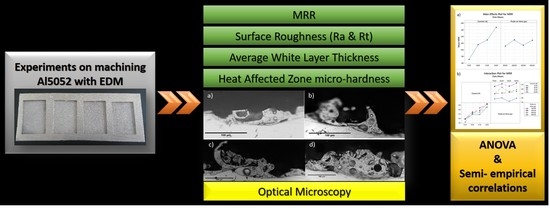
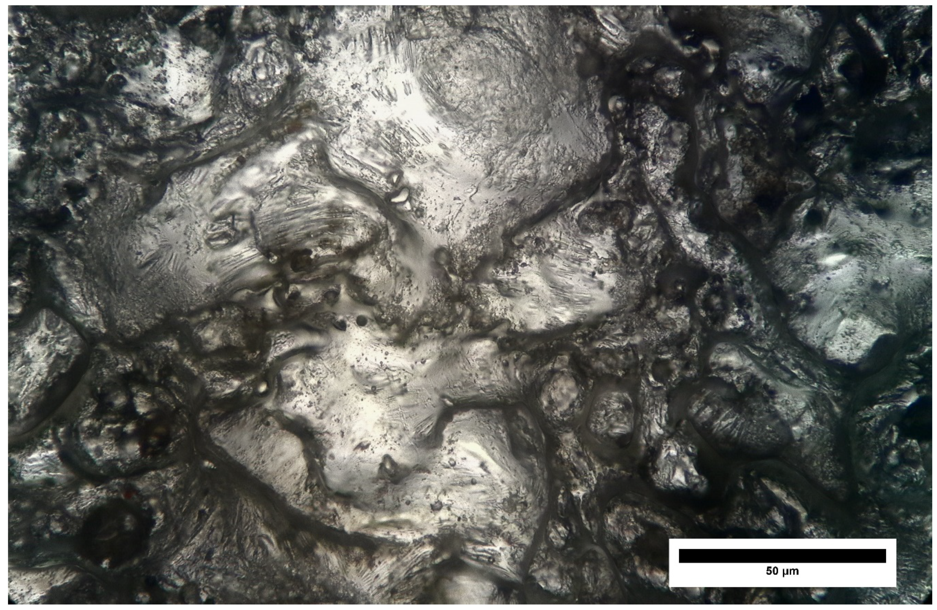
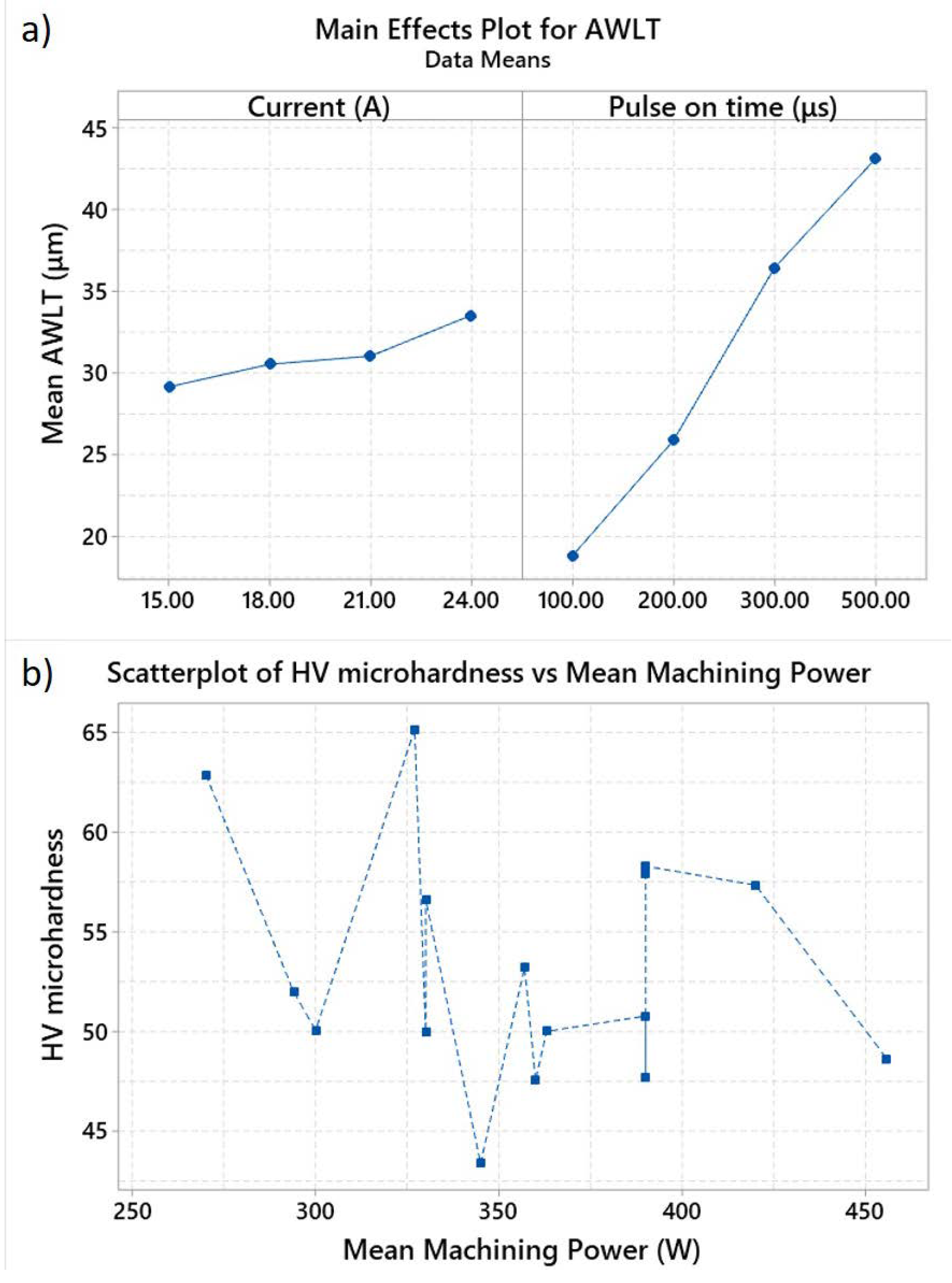
3.3. White Layer and Heat Affected Zone’s Micro-Hardness

During the EDM process, the formatted craters represent only a percentage of the total melted material, as only a small amount of the material is ejected from the cavity, while the rest returns to the solid state, forming a re-solidified layer. Furthermore, as a small portion of the ablated-vaporized material has remained in close proximity to the workpiece surface, it reattaches on the surface after the end of the pulse, forming a layer known as the re-deposited layer. The re-deposited layer has a porous structure and may contain elements of the electrode material and by-products of the dielectric fluid [11]. Re-solidified and re-deposited layers are referred as the white layer.
Surface cracks are the result of extreme variations in temperature and pressure during EDM. The probability of crack formation depends on the pulse duration, current intensity, work material properties, and dielectric fluid. Although crack mechanisms are complicated, it can be said as a simplified general rule that the density of surface cracks increases with increasing the pulse energy [12]. Nevertheless, the formation and growth of cracks and micro-cracks are in major dependence with workpiece material thermos-physical properties.
In Figure 4a–d, the WL, as it is observed by microscopy imaging, is illustrated. The machining parameters are for constant pulse current IP = 18 A and different pulse-on time, namely Ton = 100, 200, 300. and 500 μs. Figure 5a–d depict characteristic details, in magnification, of each workpiece of Figure 4.
It is evident that the average white layer thickness and the white layer’s morphological characteristics depend on the machining conditions, and the per pulse discharge energy. For Ton = 100 μs, depicted in Figure 4a and Figure 5a, the WL has an extremely thin and discontinuous profile, having only a few small globule formations. For Ton = 200 μs, Figure 4b and Figure 5b, the WL is still thin and discontinuous, but larger globules appear, indicating the simultaneous existence of re-condensed (smaller globules) and incomplete evaporated (larger globules) material formations, observations which are in line with the study of Imran et al. [6]. For Ton = 300 μs, Figure 4c, the WL profile is thicker and almost continuous, with larger globule formation, and disintegration areas, Figure 5c. For Ton = 500 μs, the WL is thick, continuous, with large globules and overlapping formations, as shown in Figure 5d. Finally, for all machining parameters, porosity is observed. For shorter pulses, the porosity is limited, with finer cavities. For higher values of Ton, due to the larger amount of trapped air, the porosity becomes more intense, forming larger cavities, as shown in Figure 5.
In Figure 6, the melted and re-solidified layer is depicted, along with its characteristics features, namely smaller and larger pockmarks, and islets that have been formed by molten material fluxes. It has to be pointed out the absence of intense cracks and micro-cracks on the machined surface, a typical characteristic of machined surfaces with EDM. It can be explained and attributed to the aluminum high thermal conductivity. Aluminum has a typical thermal conductivity of 138 W/mK, while steel has the half, or even lower. Thus, the thermal energy in aluminum is diffused faster, resulting in the occurrence of lower gradients of temperature, which are one of the major reasons of cracks development.
The AWLT and the micro-hardness of the material just beneath the WL in the HAZ were measured, and the results are presented in Table 4.
As the main effect plot for the AWLT, shown in Figure 7a, indicates, the pulse-on time Ton has the major effect on the AWLT and thus, the abovementioned microscopy observations are confirmed by the measurements. Considering a nonlinear regression between the AWLT and the machining parameters 12 and according to the experimental results, the AWLT can be expressed as function of IP and Ton through Equation (5):
A W L T = 0.743 I P 0.286 T o n 0.52 ,
with AWLT in μm, IP in A, and Ton in μs. Finally, the micro-hardness of the material, in the HAZ, is decreased, up to 43 HV, indicating a 37% decrease.
The formation of a HAZ and the subsequent reduction of the material’s micro-hardness is the result of the thermal energy flow into the workpiece. Therefore, the higher the inflow heat energy rate is, the higher effect it has on the HAZ formation. On the other hand, the formation of a WL can have a shielding effect on the HAZ formation, by protecting the bulk material from the dissipated heat. As a result, there is no clear correlation between the machining power and the material’s micro-hardness, but only evidence proving the existence of the HAZ underneath the WL, as shown in Figure 7b.

4. Conclusions

An experimental investigation of machining aluminum alloy, namely Al5052, was carried out in the current study. The studied machining parameters were the pulse current IP and the pulse-on time Ton. The MRR, the surface roughness (Ra, Rt), the AWLT, and the micro-hardness of the HAZ were measured and/or calculated. The most important emerged conclusions are:
  • The main factor which affects the MRR is the pulse current IP.
  • For optimization of the machining efficiency, the interactions between machining parameters must be considered. For the same mean machining power, different MRR were measured; however, the same MRR resulted with different mean machining powers. This is the result of interactions between pulse current and pulse-on time and the manner each parameter affects the material removal mechanism.
  • The surface roughness mainly depends on the pulse-on time, with the measured values having statistically significant difference, when changing from 100 μs to 200, 300, and 500 μs.
  • The morphology of the WL depends on the discharge energy, mostly by the pulse-on time. Increase of the pulse energy results to a thicker WL, more continuous, with bigger globule formations and more intense porosity. The AWLT can be expressed as a function of IP and Ton.
  • The material of the HAZ has decreased micro-hardness.

Author Contributions

Conceptualization, A.P.M. and P.K.-O.; Data curation, E.-L.P.; Investigation, E.-L.P. and P.K.-O.; Methodology, A.P.M., E.-L.P. and P.K.-O.; Software, E.-L.P.; Supervision, A.P.M.; Validation, E.-L.P. and P.K.-O.; Writing – original draft, E.-L.P. and P.K.-O.; Writing – review & editing, A.P.M. All authors have read and agreed to the published version of the manuscript.

Funding

This research received no external funding.

Conflicts of Interest

The authors declare no conflict of interest.

References

  1. Jahan, M.P. Electrical Discharge Machining (EDM) Types, Technologies and Applications; Nova Science Publishers: New York, NY, USA, 2015; p. 507. [Google Scholar]
  2. Abbas, N.M.; Solomon, D.G.; Bahari, M.F. A review on current research trends in electrical discharge machining (EDM). Int. J. Mach. Tools Manuf. 2007, 47, 1214–1228. [Google Scholar] [CrossRef]
  3. Khan, A.A. Electrode wear and material removal rate during EDM of aluminum and mild steel using copper and brass electrodes. Int. J. Adv. Manuf. Technol. 2008, 39, 482–487. [Google Scholar] [CrossRef]
  4. Gatto, A.; Bassoli, E.; Iuliano, L. Performance Optimization in Machining of Aluminium Alloys for Moulds Production: HSM and EDM. In Aluminium Alloys, Theory and Applications; Kvackaj, T., Ed.; IntechOpen: Rijeka, Croatia, 2011; pp. 355–376. [Google Scholar]
  5. Radhika, N.; Sudhamshu, A.R.; Chandran, G.K. Optimization of Electrical Discharge Machining Parameters of Aluminium Hybrid Composites Using Taguchi Method. J. Eng. Sci. Technol. 2014, 9, 502–512. [Google Scholar]
  6. Imran, M.; Shah, M.; Mehmood, S.; Arshad, R. EDM of Aluminum Alloy 6061 Using Graphite Electrode Using Paraffin Oil and Distilled Water as Dielectric Medium. Adv. Sci. Technol. Res. J. 2017, 11, 72–79. [Google Scholar] [CrossRef] [Green Version]
  7. Kandpal, B.C.; Kumar, J.; Singh, H. Machining of Aluminium Metal Matrix Composites with Electrical Discharge Machining - A Review. Mater. Today Proc. 2015, 2, 1665–1671. [Google Scholar] [CrossRef]
  8. Selvarajan, L.; Rajavel, J.; Prabakaran, V.; Sivakumar, B.; Jeeva, G. A Review Paper on EDM Parameter of Composite material and Industrial Demand Material Machining. Mater. Today Proc. 2018, 5, 5506–5513. [Google Scholar] [CrossRef]
  9. Dolatkhah, A.; Golbabaei, P.; Givi, M.K.B.; Molaiekiya, F. Investigating effects of process parameters on microstructural and mechanical properties of Al5052/SiC metal matrix composite fabricated via friction stir processing. Mater. Des. 2012, 37, 458–464. [Google Scholar] [CrossRef]
  10. Gostimirovic, M.; Kovac, P.; Sekulic, M.; Skoric, B. Influence of discharge energy on machining characteristics in EDM. J. Mech. Sci. Technol. 2012, 26, 173–179. [Google Scholar] [CrossRef]
  11. Jameson, E.C. Electrical Discharge Machining; Society of Manufacturing Engineers: Dearborn, MI, USA, 2001; p. 342. [Google Scholar]
  12. Rebelo, J.C.; Dias, A.M.; Kremer, D.; Lebrun, J.L. Influence of EDM pulse energy on the surface integrity of martensitic steels. J. Mater. Process. Technol. 1998, 84, 90–96. [Google Scholar] [CrossRef]
Figure 1. (a) Main effects plot for MRR. (b) Interaction plot for MRR.
Machines 08 00012 g001
Figure 2. (a) MRR vs. mean machining power. (b) MRR vs. IP and Ton.
Machines 08 00012 g002
Figure 3. Main effects plot for (a) Ra. (b) Rt.
Machines 08 00012 g003
Figure 4. WL for IP = 18 A and Ton (a) 100 μs. (b) 200 μs. (c) 300 μs. (d) 500 μs.
Machines 08 00012 g004
Figure 5. Details from the WL for IP = 18 A and Ton (a) 100 μs. (b) 200 μs. (c) 300 μs. (d) 500 μs.
Machines 08 00012 g005
Figure 6. Details of the machined surface for IP = 15 A and Ton 200 μs.
Machines 08 00012 g006
Figure 7. (a) Main effect plot for AWLT. (b) Scatterplot of micro-hardness HV vs. mean machining power.
Machines 08 00012 g007
Table 1. Chemical composition and physical properties of aluminum alloy Al5052.
Si (max)Fe (max)Cu (max)Mn (max)MgCrZn (max)Others (max)Density (g/mm3)Hardness (HV)
0.25%0.40%0.10%0.10%2.2–2.8%0.15–0.35%0.1%0.15%0.0026898
Table 2. Experimental parameters and results.
#IP
(A)
Ton
(μs)
Duty
Factor
MRR
(mm3/min)
Ra
(μm)
Rt
(μm)
AWLT
(μm)
1151000.617310.877.218
2181000.6120710.776.617
3211000.5220711.276.220
4241000.5425711.886.421
5152000.6718015.195.623
6182000.6621314.59826
7212000.5825214.496.827
8242000.5427414.5101.628
9153000.6515514.193.836
10183000.6421716113.237
11213000.5722415.2104.235
12243000.5825914.4104.437
13155000.7317714.294.439
14185000.7222417.1114.842
15215000.6223416.710542
16245000.6328019.4140.649
Table 3. p Values of 2-samples-t test for pulse current and pulse-on time.
RaIP (A) RaTon (μs)
Rt Rt
IP (A) 15182124Ton (μs) 100200300500
15 0.570.6050.469100 0.0000.0020.014
180.35 0.9170.842000.002 0.5580.131
210.540.67 0.7543000.0060.252 0.192
240.240.620.39 5000.0430.2130.425
Table 4. Average white layer thickness and micro-hardness of the heat affected zone.
No. of Experiment12345678910111213141516
AWLT (μm)18172021232627283637353739424249
Micro-hardness (HV)63655051505350485243485757585849

