Design for Six Sigma (DFSS) Applied to a New Eco-Motorbike


Abstract
:1. Introduction
2. Define
2.1. Documentation on the Environment of Use
- ⚬
- Who: Who uses the product?Two-wheel enthusiasts and speed lovers who pay attention to the environment.
- ⚬
- What: What are the uses of the product?A means of transport for short and long routes, particularly agile, fast, and of limited size.
- ⚬
- Where: Where is the product used?It is mainly used along roads and urban and extra-urban roads.
- ⚬
- When: When is it used?Mainly in spring and summer, its use is strongly linked to favorable weather conditions.
- ⚬
- Why: Why was the product chosen / why could it be chosen?It can be chosen because of its aesthetic design, performance, driving sensations, price, or environmental impact, and management and maintenance costs.
- ⚬
- How: How is the product used?The product is driven directly by its user and mainly used for the fun and pleasure provided by driving these two-wheeled vehicles, as well as by logistical needs.
2.2. Customer Needs
3. Measure
3.1. Matrix of Relative Importance
- 1 = The element of the row has the same importance as the column element.
- 0 = The element of the row has less importance than the column element.
- 2 = The row element has more importance than the column element.
3.2. Independence Matrix
3.3. Benchmarking
3.4. Top-Flop Analysis
- Wheelbase, width, seat height and weight, related to the aesthetic and dimensional characteristics.
- Power, torque, maximum speed, acceleration, characterizing the performance of the bike.
- Autonomy, battery and charging time to highlight the characteristics of an electric vehicle.
- Price, as one of the determining factors in the spread of this market.
4. Analyze
4.1. WHAT/HOW Relationship Matrix
- -
- The sum of the line values indicates which requirement is most affected by the technical specifications.
- -
- The sum of the column values indicates the priority of the actions that must be implemented, to achieve the maximum effect on the row requirements.
4.1.1. Weight
4.1.2. Battery
4.1.3. Autonomy
4.1.4. Power
4.1.5. Price
5. Design
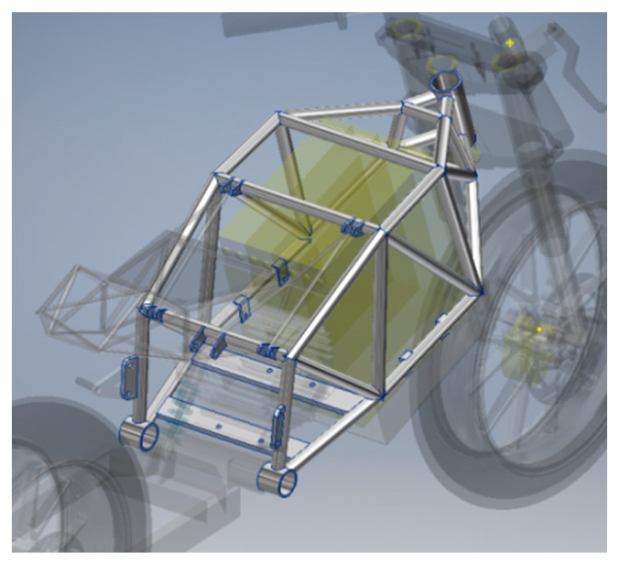
5.1. Frame Design
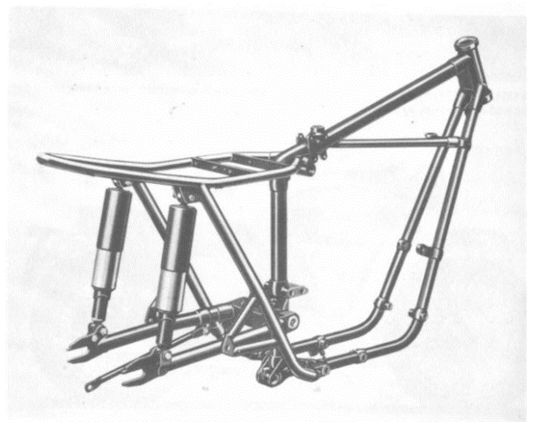
5.1.1. A Cradle
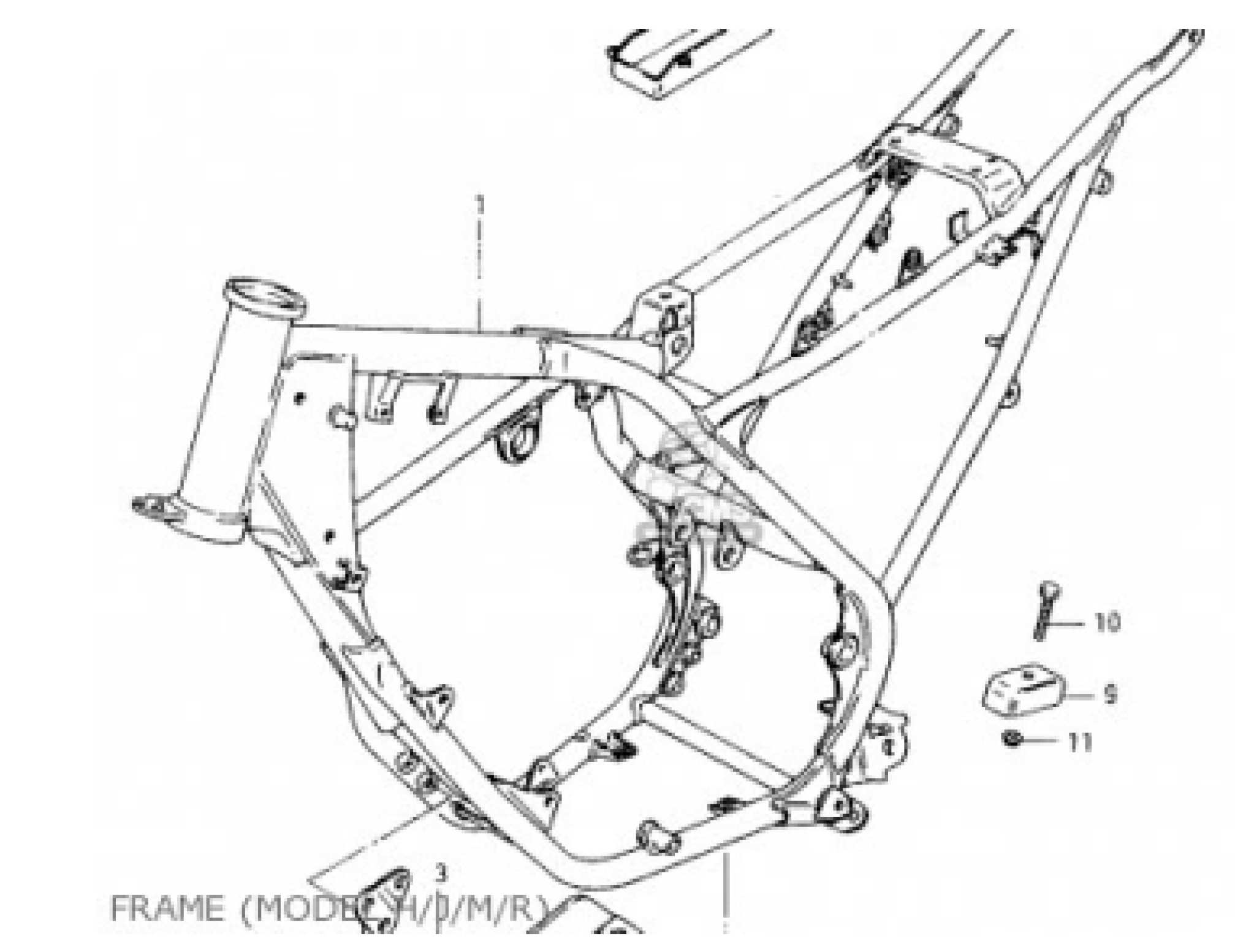
5.1.2. Perimeter
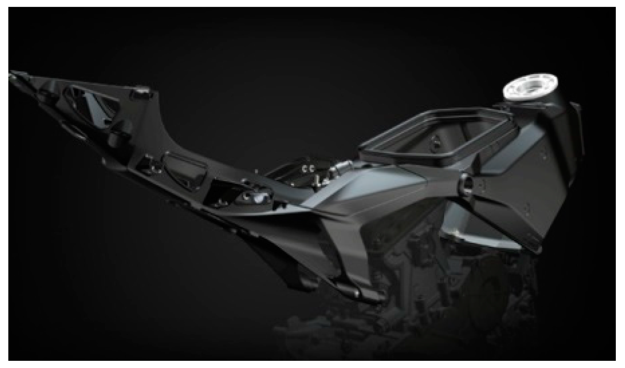
5.1.3. Monoblock
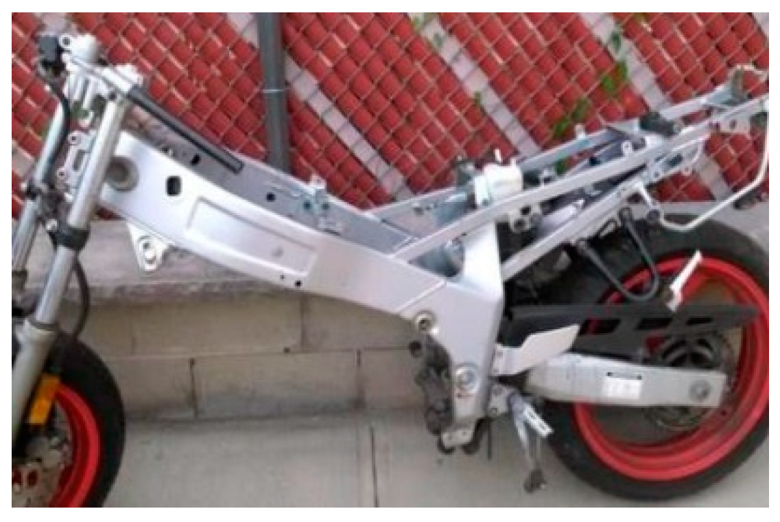
5.1.4. Trellis
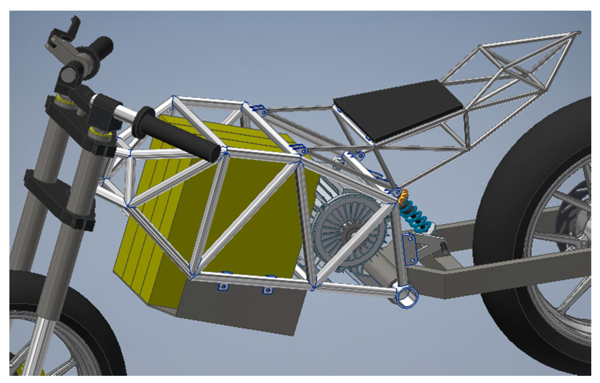
5.1.5. Design of the Electric Motorcycle
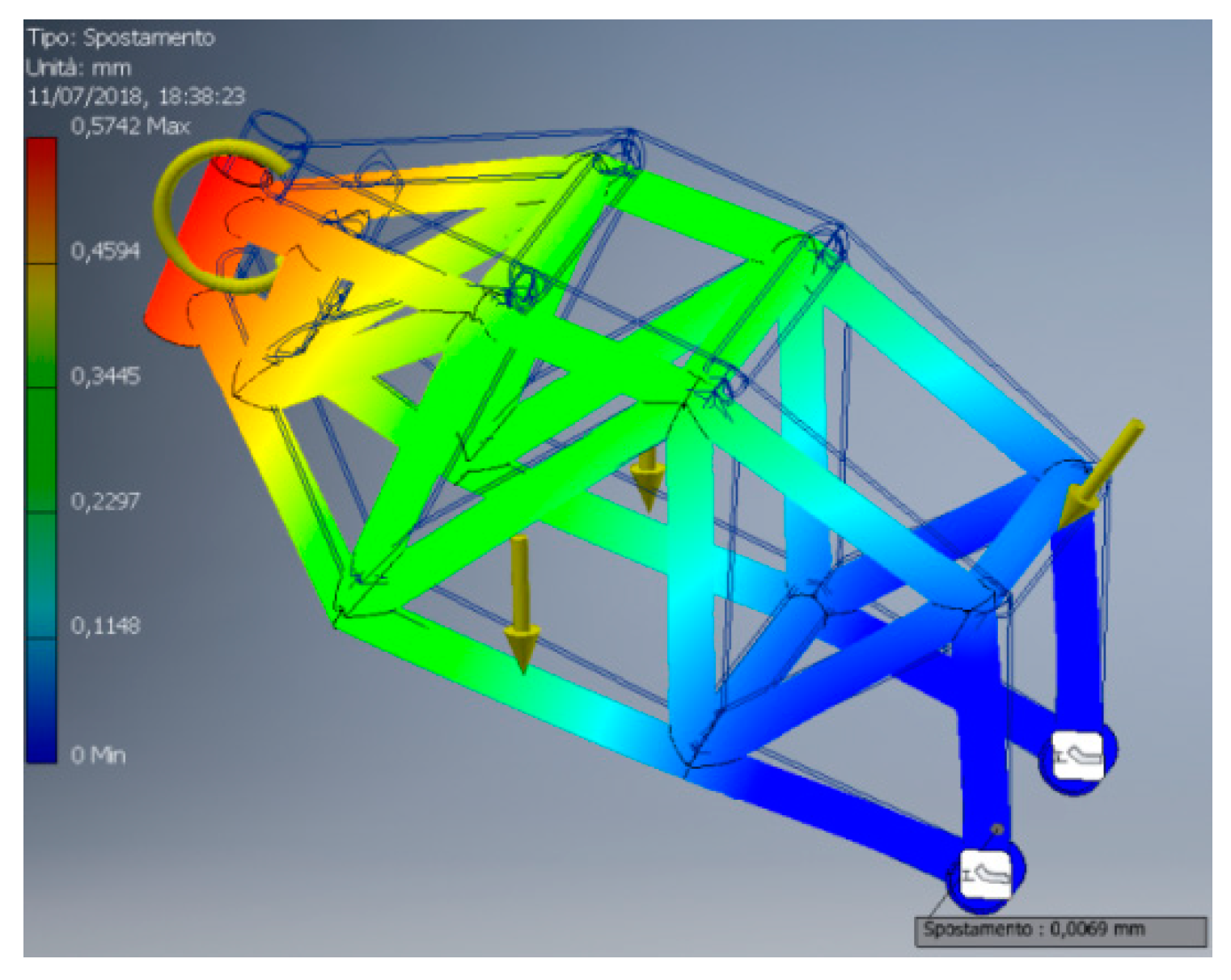
6. Validate/Verify
6.1. Irregularity in Asphalt
6.2. Braking Phase
6.3. Design Validation
- -
- Weight
- -
- Battery
- -
- Autonomy
- -
- Price
- -
- Power
7. Conclusions
Author Contributions
Funding
Conflicts of Interest
References
- Liverani, A.; Caligiana, G.; Frizziero, L.; Francia, D.; Donnici, G.; Dhaimini, K. Design for Six Sigma (DFSS) for additive manufacturing applied to an innovative multifunctional fan. Int. J. Interact. Des. Manuf. 2019, 13, 309–330. [Google Scholar] [CrossRef]
- Akao, Y. QFD, Quality Function Deployment, Landsberg; Verlag moderne Industrie: Landsberg am Lech, Germany, 1992. [Google Scholar]
- Hassan, M.F.; Jusoh, S.; Yunos, M.Z.; Arifin, A.M.T.; Ismail, A.E.; Ibrahim, M.R.; Rahim, M.Z. Application of design for six sigma methodology on portable water filter that uses membrane filtration system: A preliminary study. In Proceedings of the IOP Conference Series: Materials Science and Engineering, Beijing, China, 24–27 October 2017; Volume 243, p. 012048. [Google Scholar]
- Jiang, J.-C.; Hsu, C.-H.; Nguyen, T.-A.-T.; Dang, H.-S. Investigating the designed parameters of dual-layer micro-channel heat sink by design for six sigma (DFSS). In Proceedings of the 2017 International Conference on Applied System Innovation (ICASI), Sapporo, Japan, 13–17 May 2017; p. 1351. [Google Scholar]
- Nicolaescu, S.S.; Kifor, C.V. Teaching methodology for design for six sigma and quality techniques an approach that combines theory and practice. In Proceedings of the Balkan Region Conference on Engineering and Business Education, Sibiu, Romania, 19–22 October 2017; Volume 3, p. 328. [Google Scholar]
- Freddi, A. Imparare a Progettare (Learning to Design, in Italian); Pitagora: Bologna, Italy, 2002. [Google Scholar]
- Schmitt, F. Which Is the Best motor For Electric Vehicles (EVs) and Why? Available online: https://www.quora.com/Which-is-the-best-motor-for-electric-vehicles-EVs-and-why (accessed on 15 March 2019).
- Warner, J. The Handbook of Lithium-Ion Battery Pack Design: Chemistry, Components, Types and Terminology; Elsevier: Amsterdam, The Netherlands, 2015. [Google Scholar]
- Cocco, G. Motorcycle Design and Technology. How and Why; Giorgio Nada Editore: Vimodrone, Italy, 2004. [Google Scholar]
- Nicolò, F. Progettazione, Realizzazione e Verifica del Telaio del Progetto Motostudent; Università degli Studi di Padova: Padova, Italy, 2016. [Google Scholar]
- Analisi del Moto pre e Post urto del Veicolo. Available online: http://www.fupress.com/archivio/pdf/2787.pdf (accessed on 15 March 2019).
- Frizziero, L.; Donnici, G.; Francia, D.; Caligiana, G.; Gaddoni, A. Stylistic design engineering (SDE) for an innovative green vehicle following QFD and TRIZ applications. Int. J. Mech. Prod. Eng. Res. Dev. 2019, 9, 805–827. [Google Scholar]


| IMPORTANCE MATRIX | Performances | High Autonomy | Aesthetics | Lightness | Comfort | Price | Low Charge Times | Total |
|---|---|---|---|---|---|---|---|---|
| Performances | 1 | 0 | 2 | 1 | 1 | 1 | 0 | 6 |
| High Autonomy | 2 | 1 | 2 | 1 | 2 | 1 | 1 | 10 |
| Aesthetics | 0 | 0 | 1 | 0 | 1 | 1 | 1 | 4 |
| Lightness | 1 | 1 | 2 | 1 | 1 | 1 | 1 | 8 |
| Comfort | 1 | 0 | 1 | 1 | 1 | 1 | 0 | 5 |
| Price | 1 | 1 | 1 | 1 | 1 | 1 | 1 | 7 |
| Low charge times | 2 | 1 | 1 | 1 | 2 | 1 | 1 | 9 |
| INDEPENDENCE MATRIX | Performances | High Autonomy | Aesthetics | Lightness | Comfort | Price | Low Charge Times | Total (Dependence) |
|---|---|---|---|---|---|---|---|---|
| Performances | 3 | 9 | 9 | 21 | ||||
| High Autonomy | 3 | 9 | 3 | 15 | ||||
| Aesthetics | 3 | 3 | ||||||
| Lightness | 3 | 1 | 9 | 1 | 14 | |||
| Comfort | 1 | 3 | 3 | 3 | 10 | |||
| Price | 9 | 9 | 3 | 9 | 1 | 9 | 40 | |
| Low charge times | 3 | 9 | 9 | 21 | ||||
| Total (Independence) | 16 | 21 | 9 | 30 | 2 | 36 | 10 | 124 |
| Brand | Energica | Zero Motorcycle | Brammo | Italian Volt | Lito | Lightning | Johammer |
|---|---|---|---|---|---|---|---|
| Model | Ego | Zero SR ZF 14.4 | Empulse | Lacama | Sora | Ls-218 | J1 |
| Step [mm] | 1465 | 1410 | 1473 | 1482 | 1498 | 1455 | |
| Width [mm] | 870 | 807 | 830 | 814 | |||
| Saddle Height [mm] | 810 | 807 | 800 | 830 | 800 | 810 | 650 |
| Weight [kg] | 258 | 188 | 213 | 250 | 260 | 225 | 178 |
| Power [kW] | 107 | 52 | 40 | 70 | 42.5 | 150 | 16 |
| Torque [Nm] | 200 | 146 | 83 | 208 | 90 | 168 | 220 |
| Supply | El. | El. | El. | El. | El. | El. | El. |
| Max Speed [km/h] | 240 | 164 | 161 | 180 | 190 | 350 | 120 |
| Acceleration 0–100 km/h [s] | 2.8 | 3.3 | 4.8 | 4.6 | 4.3 | 1.8 | over 8 |
| Autonomy [km] | 200 | 217 | 200 | 180 | 200 | 175 | 200 |
| Battery [kWh] | 11.7 | 14.4 | 10.4 | 11.7 | 12 | 12 | 12.7 |
| Charging times [h] in second level station | 3.5 | 2.5 | 3.9 | 3 | 3.5 | 2 | 3.5 |
| Price [€] | 30,998 | 19,260 | 16,200 | 35,000 | 70,000 | 35,000 | 24,900 |
| Number of TOP | 0 | 2 | 3 | 0 | 2 | 4 | 2 |
| Number of FLOP | 1 | 1 | 3 | 2 | 2 | 0 | 3 |
| Delta Δ | −1 | 1 | 0 | −2 | 0 | 4 | −1 |
| Innovation Table | |
|---|---|
| Step [mm] | >1498 |
| Width [mm] | <807 |
| Saddle Height [mm] | <800 |
| Weight [kg] | <178 |
| Power [kW] | >150 |
| Torque [Nm] | >220 |
| Supply | Electricity |
| Max Speed [km/h] | >350 |
| Acceleration 0–100 km/h [s] | <1.8 |
| Autonomy [km] | >217 |
| Battery [kWh] | >14.4 |
| Charging times [h] in second level station | <2 |
| <16.200 | |
| Delta Δ | >4 |
| WHAT/HOW MATRIX | Step [mm] | Width [mm] | Saddle Height [mm] | Weight [kg] | Power [kW] | Torque [Nm] | Max Speed [km/h] | Acceleration 0–100 km/h [s] | Autonomy [km] | Battery [kWh] | Charging Times [h] in Second Level Station | Price [€] | Total |
|---|---|---|---|---|---|---|---|---|---|---|---|---|---|
| Performances | 3 | 1 | 1 | 3 | 9 | 9 | 9 | 9 | 3 | 1 | 0 | 3 | 51 |
| High Autonomy | 0 | 0 | 0 | 9 | 3 | 0 | 0 | 3 | 9 | 9 | 0 | 3 | 36 |
| Lightness | 1 | 1 | 0 | 9 | 1 | 0 | 0 | 3 | 9 | 3 | 0 | 3 | 30 |
| Price | 0 | 0 | 0 | 3 | 3 | 1 | 1 | 1 | 3 | 3 | 3 | 9 | 27 |
| Low charge times | 0 | 0 | 0 | 0 | 3 | 0 | 0 | 0 | 0 | 9 | 9 | 0 | 21 |
| Style | 1 | 1 | 1 | 1 | 0 | 0 | 0 | 0 | 0 | 0 | 0 | 3 | 7 |
| Total | 5 | 3 | 2 | 25 | 19 | 10 | 10 | 16 | 24 | 25 | 12 | 21 |
| Material | Young Module (GPa) | Density (g/cm3) | Young Module and Density Ratio (106 m2s−2) (Specific Stiffness) |
|---|---|---|---|
| Carbon fiber reinforced polymer | 181 | 1.6 | 113 |
| Magnesium | 45 | 1.738 | 26 |
| Aluminum | 69 | 2.7 | 26 |
| Titanium | 112.5 ± 7.5 | 4.5 | 25 ± 2 |
| Steel | 200 | 7.9 ± 0.15 | 25 ± 0.5 |
| 1 | Frame |
|---|---|
| 2 | Front fork |
| 3 | Swing arm |
| 4 | Suspensions |
| 5 | Electric motor |
| 6 | Single-gear transmission |
| 7 | Battery Pack |
| 8 | Inverter |
| 9 | Front wheel |
| 10 | Rear wheel |
| 11 | Brakes |
| 12 | Handlebar |
| 13 | Saddle |
| 14 | Fairings |
© 2019 by the authors. Licensee MDPI, Basel, Switzerland. This article is an open access article distributed under the terms and conditions of the Creative Commons Attribution (CC BY) license (http://creativecommons.org/licenses/by/4.0/).
Share and Cite
Frizziero, L.; Liverani, A.; Nannini, L. Design for Six Sigma (DFSS) Applied to a New Eco-Motorbike. Machines 2019, 7, 52. https://doi.org/10.3390/machines7030052
Frizziero L, Liverani A, Nannini L. Design for Six Sigma (DFSS) Applied to a New Eco-Motorbike. Machines. 2019; 7(3):52. https://doi.org/10.3390/machines7030052
Chicago/Turabian StyleFrizziero, Leonardo, Alfredo Liverani, and Lorenzo Nannini. 2019. "Design for Six Sigma (DFSS) Applied to a New Eco-Motorbike" Machines 7, no. 3: 52. https://doi.org/10.3390/machines7030052