Article

MPC Control and LQ Optimal Control of A Two-Link Robot Arm: A Comparative Study †

1
Laboratoire d’Automatique de Skikda (LAS), Faculté de Technologie, Département de Génie Électrique, Université 20 Août 1955, BP 26, Route El-Hadaeik, Skikda 21000, Algeria
2
Faculty of Electrical Engineering Tržaška 25, University of Ljubljana, Ljubljana 1000, Slovenia
*
Author to whom correspondence should be addressed.
This paper is an extended version of our paper, Model predictive control of a two-link robot arm, published in the Proceedings of the 2018 International Conference on Advanced Systems and Electric Technologies (IC_ASET), Hammamet, Tunisia, 22–25 March 2018; pp. 409–414.
Machines 2018, 6(3), 37; https://doi.org/10.3390/machines6030037
Submission received: 6 July 2018 / Revised: 8 August 2018 / Accepted: 14 August 2018 / Published: 17 August 2018
(This article belongs to the Special Issue Advanced Control Systems and Optimization Techniques)

Abstract

:
This study examined the control of a planar two-link robot arm. The control approach design was based on the dynamic model of the robot. The mathematical model of the system was nonlinear, and thus a feedback linearization control was first proposed to obtain a linear system for which a model predictive control (MPC) was developed. The MPC control parameters were obtained analytically by minimizing a cost function. In addition, a simulation study was done comparing the proposed MPC control approach, the linear quadratic (LQ) control based on the same feedback linearization, and a control approach proposed in the literature for the same problem. The results showed the efficiency of the proposed method.

1. Introduction

In recent years, the control of manipulator robots has been the subject of much research, due to the robots’ increasingly frequent use in dangerous or inaccessible environments, where human beings can hardly intervene [1,2]. These robot models are highly nonlinear which makes the control strategy very difficult. Several approaches to controlling manipulator robots are proposed in the literature. In [3], a robust control for a manipulator robot with two degrees of freedom was developed to take into account the uncertainties in the electrohydraulic servo systems. In [4], a robust control approach that allowed for friction in the model was developed to control a manipulator robot with two degrees of freedom. In [5], a coordinated fuzzy control approach was developed for a manipulator robot with actuator hysteresis and motion constraints. In addition, to reduce the harmful effects from unknown nonlinearities, an adaptive control scheme was introduced. In [6], a feed-forward neural network was developed to find a solution to the inverse kinematics problem of a planar manipulator robot with three degrees of freedom needed for generating desired trajectories in Cartesian space. In [7], a hybrid control approach for a three-link robot arm was developed. The proposed strategy of control was composed of two controllers: an independent joint controller, designed in the configuration space, and a sliding mode controller that enforced desired dynamics for the tracking error projections onto the Frenet-Serret frame. In [8], a robust control approach with constraints for an industrial robot manipulator was developed. First, the trajectory was generated, then a control based on the optimization concept was determined to follow the generated trajectory. In [9], the control of a manipulator robot using unit dual quaternions based on a kinematic model was developed. In [10], a tracking control approach using a manipulator robot with six degrees of freedom (6-DOF) was proposed. In [11], a time-optimal trajectory for robot systems was proposed using a convex optimization approach. In [12], a minimum-time control approach of the Acrobot was developed. The control strategy consisted of using a direct search algorithm for finding an optimal trajectory for the robot. In [13], an adaptive control was developed for the robot arm with LQ performance. The dynamics of the robot were highly nonlinear and the robot parameters were all assumed unavailable. In [14], a robust optimal adaptive sliding mode control using a disturbance observer was developed and tested on the robot arm. The control gains were adjusted on-line by the observer to compensate for the unknown time-varying disturbances.
In [15], three nonlinear predictive control approaches for controlling a planar two-link vertical manipulator robot were developed: an adaptive nonlinear model predictive control (nMPC) approach, a proportional–integral–derivative (PID)-based nMPC (PIDnMPC) approach, and a novel simplified nMPC (SnMPC) approach. In [16], a nonlinear model predictive control of a manipulator robot mounted on an unmanned satellite was proposed. This control consisted of two modules: a trajectory planning module (based on a trajectory optimization algorithm) and a model predictive controller. In [17], a comparative study between a generalized predictive control and a fuzzy supervisory control of a flexible single-link robot arm was proposed. In [18], a model predictive control with constraints of a flexible-link mechanism was developed. This control approach was tested on a four-link closed loop planar mechanism lying on the horizontal plane driven by a torque-controlled electric actuator. In [19], a nonlinear model predictive control of a free-flying space robot was developed and the performance of the proposed control was compared with that of a sliding mode control. In [20], a reactive constraint-based control approach was developed for controlling a mobile manipulator so it could reach its goal and avoid unknown and unpredictable obstacles. The robot’s trajectory was calculated on-line by using the model predictive method. In [21], a nonlinear predictive control structure in real-time for the visual servoing of a manipulator robot was proposed. The proposed control approach was designed to solve tasks assigned to robot manipulators with an eye-in-hand configuration. In [22], a single-input neuronal generalized predictive control approach for controlling a manipulator robot with six degrees of freedom was proposed. In [23], a model predictive control with constraints of a flexible-link manipulator robot was proposed, in order to eliminate the problem of vibration.
In contrast to the above-mentioned works, this paper presents a combination of a feedback linearization control and an MPC control approach of a two-link robot arm. The control approach design was based on the dynamic model of the robot. Since the model of the robot was nonlinear, a feedback linearization control was developed in the first step to obtain a linear system connecting so-called synthetic control signals to the respective joint angles. Next, based on the obtained linear model, a model predictive control approach was developed. The proposed solution was therefore a type of nonlinear cascade controller that was very easy to tune. In order to show the efficiency of the proposed approach, a comparative study was performed with the LQ optimal control approach and a control approach proposed in the literature for the two-link robot arm.
This paper is organized as follows. First, in Section 2, a description of the planar two-link robot arm is provided, along with its dynamic model. Then, in Section 3, the control approach for controlling the robot from an initial configuration to the final configuration using an MPC approach is presented. A linear quadratic optimal control approach is developed and the comparative study is addressed in Section 4. Finally, simulation results are presented in Section 5.

2. Dynamic Model

A planar two-link robot arm can be presented as depicted in Figure 1, where θ i , L i , and M i { i = 1 , 2 } are respectively the joint angle, the length, and the mass of the first link (i = 1) and the second link (i = 2). The gravitational acceleration is denoted by g.
The calculation of the dynamic model of this robot is based on the kinetic and potential energies. The tip of the second link is computed using the direct geometric model (DGM) as:
{ x = L 1 sin ( θ 1 ) + L 2 sin ( θ 1 + θ 2 ) y = L 1 cos ( θ 1 ) + L 2 cos ( θ 1 + θ 2 ) .
Taking into account Equation (1), the total kinetic energy of the two-link robot arm is given by the following Equation (2):
E = 1 2 ( M 1 + M 2 ) L 1 2 θ ˙ 1 2 + 1 2 M 2 L 2 2 θ ˙ 1 2 + M 2 L 2 2 θ ˙ 1 θ ˙ 2 + 1 2 M 2 L 2 2 θ ˙ 2 2 + M 2 L 1 L 2 ( θ ˙ 1 θ ˙ 2 + θ ˙ 1 2 ) cos ( θ 2 ) ,
and the potential energy is given by the following Equation (3):
U = M 1 g L 1 cos ( θ 1 ) + M 2 g ( L 1 cos ( θ 1 ) + L 2 cos ( θ 1 + θ 2 ) ) .
To find the robot motion equations, we use the formalism of Lagrange:
L = E U .
With Lagrangian L, we can solve the Euler-Lagrange equation which relies on the partial derivative of kinetic and potential energies of mechanical systems to compute the equations of motion, defined as follows:
τ = d d t ( L θ ˙ i ) L θ i ,
where L and τ = [ τ 1 τ 2 ] T are respectively the Lagrangian of the motion and the torque vector.
Developing Equation (5), the dynamic model of a robotic arm with two degrees of freedom (DOF) can be rewritten in the following form [24]:
{ M ( θ ) θ ¨ + C ( θ , θ ˙ ) + G ( θ ) = τ Y = θ ,
where:
  • θ = [ θ 1 θ 2 ] T is the vector of joint variables;
  • τ = [ τ 1 τ 2 ] T is the vector of applied torques (control input);
  • Y is the output vector;
  • G ( θ ) = [ ( M 1 + M 2 ) g L 1 sin ( θ 1 ) M 2 g L 2 sin ( θ 1 + θ 2 ) M 2 g L 2 sin ( θ 1 + θ 2 ) ] is a vector of gravity torques;
  • C ( θ , θ ˙ ) = [ M 2 L 1 L 2 ( 2 θ ˙ 1 θ ˙ 2 + θ ˙ 1 2 ) sin ( θ 2 ) M 2 L 1 L 2 θ ˙ 1 θ ˙ 2 sin ( θ 2 ) ] represents the vector of Coriolis and centrifugal forces;
  • M ( θ ) = [ D 1 D 2 D 3 D 4 ] is the inertia matrix with the following elements:
    D 1 = ( M 1 + M 2 ) L 1 2 + M 2 L 2 2 + 2 M 2 L 1 L 2 cos ( θ 2 ) D 2 = M 2 L 2 2 + M 2 L 1 L 2 cos ( θ 2 ) D 3 = D 2 D 4 = M 2 L 2 2

3. Controller Design

In this section, the development of a predictive control of a robotic arm with two DOF is presented. In that regard, we consider the nonlinear dynamic model given by Equation (6) that is also multivariable (with two control inputs and two controlled outputs). Although it is possible to design the nonlinear controllers for such systems directly, we here propose a two-step design where a feedback linearization control is developed first to make the system linear. Once the linear model was obtained, a model predictive control is designed in the next step. The final implementation of the controller can be seen as nonlinear multivariable cascade controller.

3.1. Feedback Linearization Control

The main idea of this technique is to transform the nonlinear dynamics of the system to a completely or partially linear one, so that linear control approaches can be applied to stabilize it [25,26]. In this study, the control approach with feedback linearization was developed for a dynamic model of the two-link robot arm given by Equation (6). In order to do so, the authors differentiated the output Y until the control input τ appeared. In this case, the control input τ appeared in the second derivative of the output Y. This implied that the relative degree of the system was two. The second derivative of Y can be derived from Equation (6) and is given as:
Y ¨ = θ ¨ = M ( θ ) 1 ( C ( θ , θ ˙ ) G ( θ ) + τ ) = v ,
where v = [ v 1 v 2 ] T is a synthetic control vector to this linear double-integrator system. Next, they had to find the relation between the synthetic control and the actual control torque. This feedback linearization control law is obtained from Equation (7) and is given by:
τ = M ( θ ) v + C ( θ , θ ˙ ) + G ( θ )  
Applying the control law given by Equation (8) to the nonlinear system given by Equation (6), the dynamic model of the manipulator robot with two DOF, becomes a linear double-integrator system. The relative degree was equal to two. This meant that by using the control law Equation (8), a complete linearization of the nonlinear system Equation (6) was achieved and a linear system for each joint variable was obtained. These two linear systems can be described in the transfer-function form:
θ 1 ( s ) v 1 ( s ) = 1 s 2 ​   and    θ 2 ( s ) v 2 ( s ) = 1 s 2 ,
where s denotes the independent variable of the Laplace transform.
Based on the feedback linearization given in this subsection, a model predictive control for the two-link robot arm was developed, which is the goal of the next subsection.

3.2. Model Predictive Control

In the case of a robot arm with two DOF and after application of the feedback linearization Equation (8) to the nonlinear system (6), the authors obtained the following two decoupled linear systems:
{ θ ¨ 1 = v 1 θ ¨ 2 = v 2 .
The system (10) can be easily stabilized by using a proportional–derivative (PD) controller given by the following Equation (11):
{ v 1 = k 1 ( θ 1 d θ 1 ) + k 2 ( θ ˙ 1 d θ ˙ 1 ) v 2 = k 1 ( θ 2 d θ 2 ) + k 2 ( θ ˙ 2 d θ ˙ 2 )  
where [ θ 1 d θ 2 d ] T is a vector of the desired joint variables. Note that the PD controller’s gain is infinite at high frequencies, which makes it physically not realizable. To limit the gain at high frequencies, the PD controller is usually implemented as a phase lead compensator or some other filtering technique is applied.
The closed loop system exhibits the behavior of a second order system. The gains k 1 and k 2 can be chosen as:
k 1 = w 0 2 and k 2 = 2 ζ w 0 ,
where w 0 is a natural frequency and ζ is a damping factor.
Using the gains given by Equation (12), we obtain a large field of the second order system poles. The objective of the proposed MPC control is to select a part of this domain that optimized the cost function. This last proposal will be defined and detailed later.
Now, we will develop an MPC controller (see [27,28,29]) for the first link of the robot arm. The MPC controller for the second link of the robot arm will be developed in the same way as the first.
Assuming v 1 ( t ) = v 1 is constant in the time interval [ t , t + h ] , where h is the horizon time of the prediction, and using Equation (10), the following prediction model is obtained [30]:
{ θ ˙ 1 ( t + h ) = v 1 h + θ ˙ 1 ( t ) θ 1 ( t + h ) = 1 2 v 1 h 2 + θ ˙ 1 ( t ) h + θ 1 ( t )  
Next, given the reference angle of the first link θ 1 d (constant), the proposed one-horizon time quadratic cost function for stabilizing the system is defined by:
J = e 1 2 ( t + h ) + ρ e ˙ 1 2 ( t + h ) ,
where e 1 ( t + h ) = θ 1 d θ 1 ( t + h ) is the predicted angle error, and e ˙ 1 ( t + h ) = 0 θ ˙ 1 ( t + h ) is the predicted velocity error. The horizon time h and the weight ρ are both positive real constants (control parameters) to be determined later. The criterion J is completed by introducing the prediction model (13) into (14). The idea of the proposed control law is to find the constant v 1 that minimizes the criterion J. This is done by choosing v 1 that makes the partial derivative J v 1 equal to 0. The obtained solution
v 1 = k 1 ( θ 1 d θ 1 ( t ) ) k 2 θ ˙ 1 ( t ) ,
with the control gains given by
k 1 = 2 h 2 + 4 ρ and k 2 = 2 h 2 + 4 ρ h 3 + 4 ρ h ,
is not constant in the time interval [ t , t + h ] as assumed initially, but the proposed control law was nonetheless based on this solution. In addition, a more general control law is obtained if the reference value for the angle is allowed to change. Furthermore, the feed-forward and the feed-back gains that are not necessarily constant are assumed. Therefore, the following control law is proposed:
v 1 ( t ) = k 1 ( θ 1 d ( t ) θ 1 ( t ) ) k 2 θ ˙ 1 ( t ) .
The block diagram of the closed-loop system can be presented as depicted in Figure 2, where θ 1 d and θ 2 d are respectively the reference joint angle of the first and the second link of the robot. As the feedback linearization completely decouples the control of the first and the second joint (see Equation (15)), different parameters can in general be used for both control loops. However, the authors chose to use the same controller for the second joint as the one proposed for the first joint:
v 2 ( t ) = k 1 ( θ 2 d ( t ) θ 2 ( t ) ) k 2 θ ˙ 2 ( t ) .
Concerning the system response, the control goal was that the joint angles follow their references with dynamics of the second order system given by the following transfer function w 0 2 / ( s 2 + 2 ζ w 0 s + w 0 2 ) , where ζ is a damping factor and w 0 is a natural frequency.
Using the MPC controller given by Equation (15) to stabilize the system (10), the transfer function of the whole closed-loop is given by:
θ 1 ( s ) θ 1 d ( s ) = k 1 s 2 + k 2 s + k 1 .
Taking into account Equations (16) and (19) and the dynamics of the second order system, the following is obtained:
2 ζ w 0 = 2 h 2 + 4 ρ h 3 + 4 ρ h .
w 0 2 = 2 h 2 + 4 ρ .
From Equation (21), the weight factor is:
ρ = 2 ( w 0 h ) 2 4 w 0 2 .
Substituting Equation (22) into Equation (20), he following second order equation is obtained:
w 0 2 h 2 4 ζ w 0 h + 2 = 0 ,
where h is the variable to look for. Bu writing
w 0 h = λ ,
Equation (23) becomes:
λ 2 4 ζ λ + 2 = 0 .
The solutions,
λ 1 , 2 = 2 ζ ± 4 ζ 2 2 ,
are real if and only if 4 ζ 2 2 0 ζ 2 / 2 .
To obtain a positive weight factor ρ , from Equation (22), λ 1 , 2 2 < 2 is required:
2 ( 4 ζ 2 2 ) ± 4 ζ 4 ζ 2 2 < 0 .
It was known that 4 ζ 2 2 0 (for real solutions) and, therefore, a larger solution would never satisfy this inequality. Therefore, only the smaller solution was kept. It was very easy to verify that outcome:
2 ( 4 ζ 2 2 ) ζ 4 ζ 2 2 < 0 .
After choosing a design parameter ζ = 0.9 and selecting an appropriate natural frequency w 0 , the authors determine the parameter h from Equations (24) and (26). With the horizon time defined, they used Equation (22) to determine the weight factor ρ . The closed-loop performance of the system was computed for each selected value of the natural frequency w 0 . and the results are summarized in Table 1 where:
  • the natural frequency w 0 is the chosen design parameter;
  • the horizon time h and the weight factor ρ are obtained using the above described procedure; Min τ i { i = 1 , 2 } and Max τ i { i = 1 , 2 } are the minimum and the maximum of the respective applied torques; the settling time t r ± 5 % θ i { i = 1 , 2 } corresponds to the times needed for the joint angles to settle within the band (±5%) of the final value;
  • D θ i { i = 1 , 2 } are the overshoots of the joint angles (in %) when a step change is applied to its reference;
  • and i { 1 , 2 } is the index of the joint.
After analyzing Table 1, it was observed that the horizon time h had an influence on the variation range of the control signals (robot torques): short horizon time implied a large variation range of the robot torques.
To obtain an acceptable control signal range ( max ( | τ i | ) 100 Nm for i = { 1 , 2 } ) [24], the authors chose the horizon time h = 0.1961 (s) and the weight factor ρ = 0.0312 .

4. Linear Quadratic Optimal Control

As in Section 3.2, the linear system given by Equation (10) was considered to determine a linear quadratic (LQ) optimal control [31,32,33,34] for the two-link robot arm.
The error e i between the actual angle θ i and the desired angle θ i d is defined as:
e i = θ i d θ i i = 1 , 2 .
The desired angle θ i d { i = 1 , 2 } is constant. Differentiating the Equation (29) twice, the following equation is obtained:
e ¨ i = θ ¨ i = v i i = 1 , 2  
If a a single decoupled linear system is considered:
e ¨ 1 = v 1 = v 1 .
The state space representation of the system (31) is given by:
{ z ˙ = A z + B v 1 ϑ = C z ,
where:
  • z = [ z 1 z 2 ] T = [ e 1 e ˙ 1 ] T n is a state vector;
  • ϑ m is the output vector;
  • v 1 is the synthetic control of the first joint of the robot;
  • A = [ 0 1 0 0 ] , B = [ 0 1 ] and C = [ 1 0 ] .
If the objective cost function is considered:
J = 0 + ( z T Q z + v 1 T R v 1 ) d t ,
where:
  • Q = [ 1 0 0 0 ] is a symmetric positive semi-definite matrix,
  • and R is a positive constant.
The objective cost function is minimized using the following linear quadratic optimal control:
v 1 = R 1 B T P z ( t ) ,
where: P = [ P 1 P 2 P 2 P 3 ] is the solution to the following so-called Riccati Equation:
P A + A T P P B R 1 B T P + Q = 0 .
The solution of the Riccati Equation (35) is:
P = [ 2 R 4 R R 2 R R ] .
Therefore, the linear quadratic optimal control v 1 = v 1 is given by the following control law:
v 1 = R 1 ( P 2 z 1 ( t ) + P 3 z 2 ( t ) ) = k 1 e 1 ( t ) + k 2 e ˙ 1 ( t ) ,
where k 1 = R 1 R    and    k 2 = R 1 2 R R . Note that the control law for the second joint is obtained following the same steps.
The block diagram of the closed-loop system resembled the one depicted in Figure 2—they only differed in the leftmost box that implemented the MPC control Equation (17) in one case and the LQ optimal control given by Equation (37) in the other.
Using the control law given by Equation (37), the system performance was computed for different values of R and they are summarized in Table 2.
Comparing Table 1 and Table 2, the authors noticed that, using the proposed model predictive control approach, a better system performance was obtained than by using the LQ optimal control approach. Using an MPC control approach, a fast convergence of the joint variables to the desired angles was obtained and the convergence was without overshooting. In addition, they noticed that by using the MPC control and the LQ optimal control, a better system performance was obtained than by using the PID control approach presented by David and Robles [24]. Furthermore, the mathematical development of the proposed LQ optimal control approach was only valid in the case where the desired angle was a constant or was ramp-like. The proposed MPC control approach, however, was valid for any desired angle.

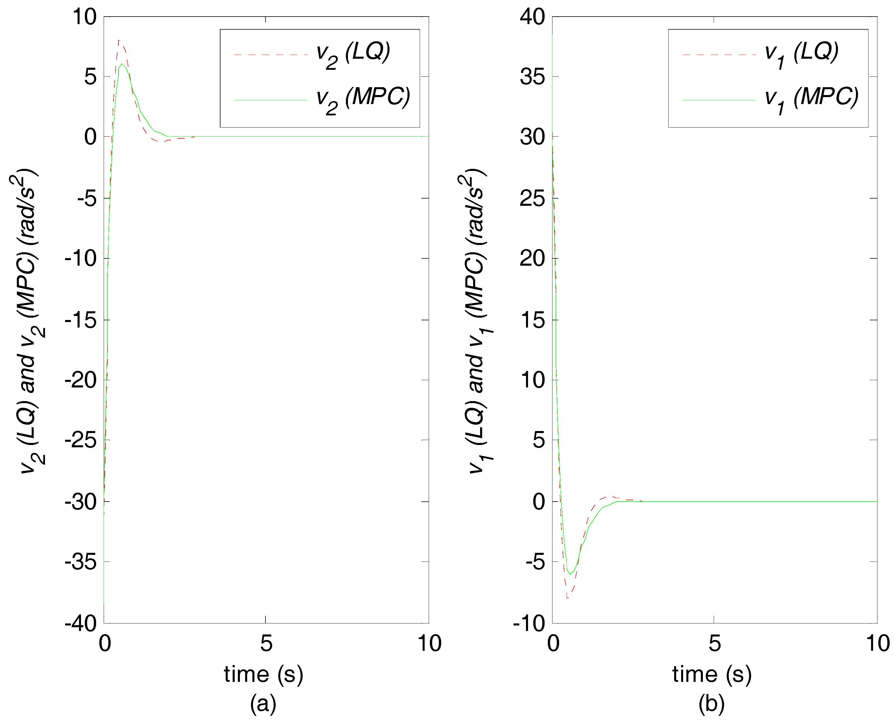
5. Simulation Results

In order to illustrate the efficiency of the proposed MPC controller, a simulation study and the comparison with the LQ optimal control approach were performed. For each approach, the authors selected the corresponding parameters so that the maximum torque was strictly less than and as close as possible to 100 Nm. This last condition was met in the case of the LQ optimal control approach for R = 1/150 with a max ( | τ 1 | ) 97 Nm . The same condition was met in the case of the MPC control approach for (h = 0.1961 (s) and ρ = 0.0312 ) with a max ( | τ 1 | ) 97 Nm .
For simulation purposes, the authors assumed that the mass and the length of the first and the second links of the robot arm were M i = ( 1 , 2 ) = 1 ( kg ) and L i = ( 1 , 2 ) = 1 ( m ) , respectively. The initial and the desired orientations of the first and the second links of the robot arm were θ 1 ( 0 ) = π / 2 , θ 2 ( 0 ) = π / 2 , θ 1 d = π / 2 and θ 2 d = π / 2 , respectively. According to the selected parameters of the two proposed approaches of control, the gains of the MPC controller were k 1 = 12.25 ; k 2 = 6.30 , and the gains of the LQ optimal controller were k 1 = 12.24 ; k 2 = 4.94 .
Figure 3a represents the trajectory of the end effector of the robot arm with the final position of both joints depicted. Figure 3b presents a zoom image of the end-effector of the robot in its final position. The trajectory (full line) computed using the MPC control is observed arriving directly to the goal, unlike the trajectory (dotted-line) computed using the LQ control.
Figure 4a,b represent the comparison between the convergence of the joint angles θ 2 and θ 1 , respectively, to their reference values, using the MPC control and the LQ control. It is observed that the MPC control approach results in a fast and asymptotic convergence of both joint variables and without overshooting.
Figure 5a,b show the comparison between the robot torques τ 2 and τ 1 , respectively, that have been obtained, using the MPC control and the LQ optimal control. It is observed that by using the MPC control approach, the energy consumption is lower than by using the LQ optimal control.
Figure 6a,b depict the robot synthetic controls v 2 and v 1 given by Equation (15). As can be seen, the synthetic controls reach zero when the end-effector of the robot reaches its objective.
The convergence of the joint-angle errors e 2 and e 1 of the two-link robot arm towards zero using the two proposed approaches of control are depicted in Figure 7a,b, respectively.

6. Conclusion

This article proposes a novel MPC control approach for a two-link robot arm with two degrees of freedom. The technique consisted of linearizing a nonlinear dynamic model of the robot by using a feedback linearization control. Next, based on the obtained linear model, an MPC controller was developed that was tuned by choosing the parameters h and ρ . In order to demonstrate the effectiveness of the proposed approach, the authors performed a comparative study with the LQ control approach. From the results obtained and presented in this article, it can be stated that the proposed MPC control approach gives a better system performance than the LQ optimal control approach. In addition, both proposed approaches (MPC control and LQ control) give a better system performance than the PID control technique proposed by David and Robles [24]. In the future, the authors plan to test the proposed MPC control on a real robot, to verify this method’s robustness.

Author Contributions

E.-H.G. (El-Hadi Guechi) proposed the idea of the model predictive control approach of a two-link robot arm, developed its theory and carried out the implementation of the proposed control approach in the MATLAB environment. In addition, he proposed the LQ control approach for this robot and wrote the manuscript with the help of S.B. (Sašo Blažič), Y.Z. (Youcef Zennir), and S.B. (Samir Bouzoualegh). S.B. (Sašo Blažič) verified the theory and the mathematical proof, and he participated with E.-H.G. (El-Hadi Guechi) to carry out the discussion of the simulation results. All authors contributed to the final manuscript.

Funding

This research was funded by the Ministry of Higher Education and Scientific Research of Algeria [CNEPRU: J0201620140014].

Acknowledgments

The authors thank the editor and the reviewers for their valuable comments.

Conflicts of Interest

The authors declare no conflict of interest. The funders had no role in the design of the study; in the collection, analyses, or interpretation of data; in the writing of the manuscript, and in the decision to publish the results.

References

  1. Chaudhary, H.; Panwar, V.; Prasad, R.; Sukavanam, N. Adaptive neuro fuzzy based hybrid force/position control for an industrial robot manipulator. J. Intell. Manuf. 2016, 27, 1299–1308. [Google Scholar] [CrossRef]
  2. Zanotto, V.; Gasparetto, A.; Lanzutti, A.; Boscariol, P.; Vidoni, R. Experimental Validation of Minimum Time-jerk Algorithms for Industrial Robots. J. Intell. Robot. Syst. 2011, 64, 197–219. [Google Scholar] [CrossRef]
  3. Guoa, Q.; Yub, T.; Jiangc, D. Robust H positional control of 2-DOF robotic arm driven by electro-hydraulic servo system. ISA Trans. 2015, 59, 55–94. [Google Scholar] [CrossRef] [PubMed]
  4. Plooij, M.; Wolfslag, W.; Wisse, M. Robust feedforward control of robotic arms with friction model uncertainty. Robot. Autom. Syst. 2015, 70, 83–91. [Google Scholar] [CrossRef]
  5. Liu, Z.; Chen, C.; Zhang, Y.; Chen, C.L.P. Coordinated fuzzy control of robotic arms with actuator nonlinearities and motion constraints. Inf. Sci. 2015, 296, 1–13. [Google Scholar] [CrossRef]
  6. Duka, A.-V. Neural Network based Inverse Kinematics Solution for Trajectory Tracking of a Robotic Arm. Procedia Technol. 2014, 12, 20–27. [Google Scholar] [CrossRef]
  7. Uzunovic, T.; Baranb, E.-A.; Golubovicc, E.; Sabanovicd, A. A novel hybrid contouring control method for 3-DOF robotic manipulators. Mechatronics 2016, 40, 178–193. [Google Scholar] [CrossRef]
  8. Zanchettin, A.M.; Rocco, P. Motion planning for robotic manipulators using robust constrained control. Control Eng. Pract. 2017, 59, 127–136. [Google Scholar] [CrossRef]
  9. Özgüra, E.; Mezouarb, Y. Kinematic modeling and control of a robot arm using unit dual quaternions. Robot. Autom. Syst. 2016, 77, 66–73. [Google Scholar] [CrossRef]
  10. Markusa, E.D.; Ageeb, J.T.; Jimohc, A.A. Flat control of industrial robotic manipulators. Robot. Autom. Syst. 2017, 87, 226–236. [Google Scholar] [CrossRef]
  11. Verscheure, D.; Demeulenaere, B.; Swevers, J.; De Schutter, J.; Diehl, M. Practical Time-Optimal Trajectory Planning for Robots: A Convex Optimization Approach. IEEE Trans. Autom. Control 2009, 54, 2318–2327. [Google Scholar] [CrossRef]
  12. Boone, G. Minimum-time Control of the Acrobot. In Proceedings of the IEEE Intemational Conference on Robotics and Automation, New Mexico, NM, USA, 20–25 April 1997; pp. 3281–3287. [Google Scholar]
  13. Kai, C.-Y.; Huang, A.-C. Adaptive LQ control of robot manipulators. In Proceedings of the 9th IEEE Conference on Industrial Electronics and Applications, Hangzhou, China, 9–11 June 2014. [Google Scholar] [CrossRef]
  14. Chen, K.-Y. Robust Optimal Adaptive Sliding Mode Control with the Disturbance Observer for a Manipulator Robot System. Int. J. Control Autom. Syst. 2018, 1–15. [Google Scholar] [CrossRef]
  15. Wilson, J.; Charest, M.; Dubay, R. Non-linear model predictive control schemes with application on a 2 link vertical robot manipulator. Robot. Comput. Integr. Manuf. 2016, 41, 23–30. [Google Scholar] [CrossRef]
  16. Rybus, T.; Seweryn, K.; Sasiadek, J.Z. Control system for free-floating space manipulator based on nonlinear model predictive control (NMPC). J. Intell. Robot. Syst. 2017, 85, 491–509. [Google Scholar] [CrossRef]
  17. Boucetta, R. Generalized Predictive Control for a Flexible Single-Link Manipulator. Comput. Inf. Syst. Ind. Manag. 2013, 499–510. [Google Scholar] [CrossRef]
  18. Boscariol, P.; Gasparetto, A.; Zanotto, V. Model Predictive Control of a Flexible Links Mechanism. J. Intell. Robot. Syst. 2010, 58, 125–147. [Google Scholar] [CrossRef]
  19. Kayastha, S.; Shi, L.; Katupitiya, J.; Pearce, G. Nonlinear model predictive control of a planar three-link space manipulator. In Proceedings of the 11th Asian Control Conference (ASCC), Gold Coast, QLD, Australia, 17–20 December 2017. [Google Scholar] [CrossRef]
  20. Avanzini, G.-B.; Zanchettin, A.-M.; Rocco, P. Reactive constrained model predictive control for redundant mobile manipulators. Intell. Autom. Syst. 2015, 1301–1314. [Google Scholar] [CrossRef]
  21. Burlacu, A.; Copot, C.; Lazar, C. Predictive control architecture for real-time image moments based servoing of robot manipulators. J. Intell. Manuf. 2014, 25, 1125–1134. [Google Scholar] [CrossRef]
  22. Durmuş, B.; Temurtaş, H.; Yumuşak, N.; Temurtaş, F. A study on industrial robotic manipulator model using model based predictive controls. J. Intell. Manuf. 2009, 20, 233–241. [Google Scholar] [CrossRef]
  23. Boscariol, P.; Gasparetto, A.; Zanotto, V. Model predictive control of a flexible links mechanism. J. Intell. Robot. Sys. 2010, 58, 125–147. [Google Scholar] [CrossRef]
  24. David, I.; Robles, G. PID Control Dynamics of A Robotics Arm Manipulator with Two Degrees of Freedom. Control De Procesos y Robótica. 2012, pp. 1–7. Available online: https://fr.slideshare.net/popochis/pid-control-dynamics-of-a-robotic-arm-manipulator-with-two-degrees-of-freedom (accessed on 4 April 2017).
  25. Khalil, H.K. Nonlinear Systems, 3rd ed.; Prentice Hall Inc.: Upper Saddle River, NJ, USA, 2002; ISBN 13: 978-0130673893. [Google Scholar]
  26. Farzin, P.; Yarmahmoudi, M.H.; Mirzaie, M.; Emamzadeh, S.; Hivand, Z. Design novel fuzzy robust feedback linearization control with application to robot manipulator. J. Intell. Syst. Appl. 2013, 5, 1–10. [Google Scholar] [CrossRef]
  27. Magni, L.; Scattolini, R.; Aström, K. Global stabilization of the inverted pendulum using model predictive control. In Proceedings of the 15th IFAC World Congress, Barcelona, Spain, 21–26 July 2002; pp. 141–146. [Google Scholar]
  28. Gawthrop, P.J.; Wang, L. Intermittent predictive control of an inverted pendulum. Control Eng. Pract. 2006, 14, 1347–1356. [Google Scholar] [CrossRef] [Green Version]
  29. Mills, A.; Wills, A.; Ninness, B. Nonlinear model predictive control of an inverted pendulum. In Proceedings of the American Control Conference, St. Louis, MO, USA, 10–12 June 2009; pp. 2335–2340. [Google Scholar]
  30. Guechi, E.-H.; Bouzoualegh, S.; Messikh, L.; Blažic, S. Model predictive control of a two-link robot arm. In Proceedings of the 2nd International Conference on Advanced Systems and Electric Technologies, Hammamet, Tunisia, 22–25 March 2018; pp. 409–414. [Google Scholar] [CrossRef]
  31. Bauer, P.; Bokor, J. Development and performance evaluation of an infinite horizon LQ optimal tracker. Eur. J. Control 2018, 39, 8–20. [Google Scholar] [CrossRef] [Green Version]
  32. Ntogramatzidis, L.; Ferrante, A. On the solution of the Riccati differential equation arising from the LQ optimal control problem. Syst. Control Lett. 2010, 59, 114–121. [Google Scholar] [CrossRef]
  33. Precup, R.-E.; Angelov, P.; Costa, B.S.J.; Sayed-Mouchaweh, M. An overview on fault diagnosis and nature-inspired optimal control of industrial process applications. Comput. Ind. 2015, 74, 75–94. [Google Scholar] [CrossRef]
  34. Precup, R.-E.; Sabau, M.-C.; Petriu, E.M. Nature-inspired optimal tuning of input membership functions of Takagi-Sugeno-Kang fuzzy models for anti-lock braking systems. Appl. Soft Comput. 2015, 27, 575–589. [Google Scholar] [CrossRef]
Figure 1. Two-link robot arm.
Machines 06 00037 g001
Figure 2. Closed-loop system (model predictive control).
Machines 06 00037 g002
Figure 3. (a) Final position: the robot end-effector reaches its objective point; (b) Zoom image of the end-effector in its final position.
Machines 06 00037 g003
Figure 4. Comparison between linear quadratic (LQ) and model predictive control (MPC) controls of a real and reference orientations: (a) Real and the desired orientations of the second link of the robot; (b) Real and the desired orientations of the first link of the robot.
Machines 06 00037 g004
Figure 5. Comparison between LQ and MPC controls of the robot torques: (a) Torques of the robot’s second link; (b) Torques of the robot’s first link.
Machines 06 00037 g005
Figure 6. Comparison between LQ and MPC controls of the robot synthetic controls: (a) Synthetic controls of the robot’s second link; (b) Synthetic controls of the robot’s first link.
Machines 06 00037 g006
Figure 7. Comparison of the errors in the joint angles, using LQ and MPC controls.
Machines 06 00037 g007
Table 1. System performance for different values of natural frequency.
w 0
(rad/s)
h (s)ρMin τ1
(Nm)
Max τ1
(Nm)
Min τ2
(Nm)
Max τ2
(Nm)
t r ± 5 % θ 1
(s)
t r ± 5 % θ 2
(s)
Dθ1 (%)Dθ2 (%)
10.68640.3822−20.2126.28−0.781.434.864.860.50.5
20.34320.0955−22.2045.14−3.135.642.422.420.50.5
3.50.19610.0312−33.3396.97−9.5717.541.41.40.50.5
40.17160.0239−39.46120.49−12.5622.921.221.220.50.5
Table 2. System performance for different values of R.
RMin τ1
(Nm)
Max τ1
(Nm)
Min τ2
(Nm)
Max τ2
(Nm)
t r ± 5 % θ 1
(s)
t r ± 5 % θ 2
(s)
Dθ1 (%)Dθ2 (%)
1−21.1526.28−1.211.766.196.1913.5613.56
1/100−39.4682.83−12.2117.801.961.9613.5613.56
1/150−44.8896.95−14.7521.481.781.7813.5613.56
1/200−49.19108.85−17.0925.031.641.6413.5613.56

