1. Introduction
Programmable Logic Controllers (PLCs) are special-purpose computers that are widely used in industry for control and automation of machinery and processes. PLCs are programmed using languages specified by the International Electrotechnical Commission (IEC) 61131-3 standard [
1], variations of those languages, or languages specific to the vendor and PLC platform. The quality of PLC software has a direct impact on production efficiency [
2]. For example, PLC software may sequence equipment differently than intended by the equipment designer, or interlocked equipment may hold in a wait state longer than necessary. Such software may still produce products correctly, but waste time and/or energy unnecessarily.
Software engineering is a large and well-studied field [
3]. Some research has been published on how to apply concepts and theories such as Petri nets, discrete event systems theory, etc. to the development of PLC software. However, this work has had little impact on PLC programming practice because it is too complex for most PLC programmers to apply. Some work has been done to apply software engineering principles to PLC software development, such as recognizing design patterns [
4], using an object-oriented approach [
5] and proposing new, high-level graphical languages [
6]. This is a good start. However, searching the literature for terms such as “PLC software architecture,” “PLC software framework,” “scalable PLC software,” etc. yields few if any results that are easily applied to practice. In fact, broader literature searches for “PLC software” or “PLC programming” yield few papers, most of which are too complex to apply to actual practice. There is a need to close the gap between academia and industrial practice.
Programmable Logic Controllers (PLCs) are becoming more sophisticated, and it seems the trend will continue for some time. Many vendors are using the term Programmable Automation Controller (PAC) to emphasize that the current generation is much more powerful than previous generations of PLCs [
7,
8]. In the past, PLCs were often programmed by people with little or no formal background in computer programming. Today, programs are often written by people having a much better background in computer programming, with a good understanding of data structures, object-oriented programming principles, etc. Naturally, these people want to use their knowledge and take advantage of the programming capabilities offered by the latest PLCs.
Unlike most other types of software, PLC programs are often seen and used by the end-user as a troubleshooting tool. The person doing the troubleshooting, often an electro-mechanical technician, may have limited programming skills because they have many other responsibilities. This is a key point that programmers must keep in mind when they develop PLC programs. The program that is easiest to troubleshoot is often the simpler one, not the more elegant or sophisticated one. Over the lifetime of a production line, with other factors being equal, the line that is easiest to troubleshoot will probably have higher up-time and therefore be more efficient and profitable.
Recently, a leading food manufacturer commissioned a completely rewritten PLC program that controls a major production line [
9]. After ten full months running the new program, the production efficiency was 6.1% higher on average than it was during the ten full months prior to the conversion. The Supervisory Control and Data Acquisition (SCADA) system and Human-Machine Interface (HMI) screens were modified to communicate with the new PLC program. Some additional informational screens were added, but the control screens used by operators were not changed significantly and operator procedures remained the same. The PLC hardware and the equipment on the line were not changed. The only changes made were to the control software, primarily the PLC software. The new PLC software uses an architecture and framework that favors simplicity, replacing an architecture and framework that favored more sophistication and used more of the advanced capabilities of the PLC processor. As such, this project provides an unusual opportunity to quantify the impact of different PLC software architectures on production efficiency. This is only one case study, so many conclusions drawn from the experience require further investigation to confirm. However, it is safe to conclude that two different PLC programs for the same production line can result in significantly different efficiencies that equate to significant differences in profitability. This, in turn, motivates the need for research in software architecture and software framework for PLC software, as well as research in applying other knowledge from the field of software engineering to PLC software development.
This paper gives a brief background on PLC programming languages in
Section 2. An overview of the old and new PLC software architecture and framework is given in
Section 3. Implementation details of framework elements of the old and new programs are compared in
Section 4.
Section 5 presents objective, quantifiable results from the conversion experience.
Section 6 is a more subjective discussion of the results, suggesting possible reasons for the improvements.
Section 7 discusses suggestions for further research, asking how PLC programs should be written and what they should look like in the future.
2. PLC Programming Languages
Most PLCs can be programmed using several different languages. Some of the most common languages are:
Ladder Diagram (LD). LD is a graphical language that was developed to mimic hard-wired relay logic.
Structured Text (ST). ST is a textual language that is similar to the BASIC programming language.
Sequential Function Chart (SFC). SFC is a graphical language that resembles a flow chart.
Function Block Diagram (FBD). FBD is a graphical language where blocks are connected to show data flow. Blocks include logic functions, math functions, timers, proportional-integral-derivative (PID) control, etc.
Most PLCs allow a program to consist of routines written in different languages. For example, LD might be used for much of the program, ST might be used for math-intensive computations, SFC might be used to drive sequenced operations and FBD might be used for control of continuous processes. Ladder diagram is a very commonly used language and is used in the examples in this paper. Ladder diagram can be used to do anything the other languages can do, although other languages may be easier to use for some applications.
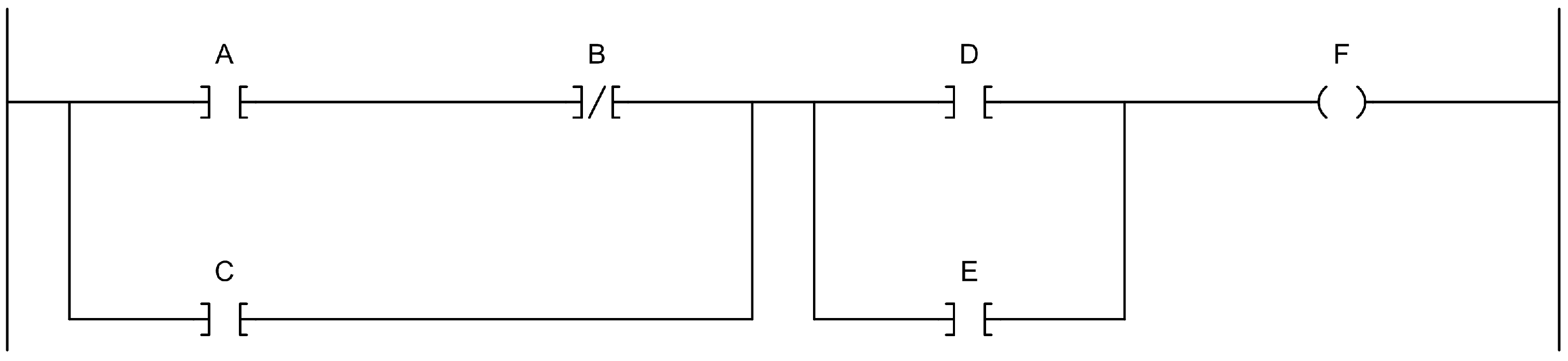
Figure 1 shows a basic example of a ladder diagram program that implements the logic function
, where ‘·’ denotes the logical AND function, ‘+’ denotes the logical OR function and
is the complement of
B (i.e., NOT B). The symbol under A in
Figure 1 is called a normally open contact that is logically true if
. The symbol under B in
Figure 1 is called a normally closed contact that is logically true if
. Symbols connected in series, such as A and B, are logically ANDed together. Symbols connected in parallel, such as D and E, are logically ORed together. The symbol under F is called a coil that is logically true if the logic leading into it is true and is false if the logic leading into it is false. The function implemented by the example in
Figure 1 could be written in pseudocode as:
        if (((A and not B) or C) and (D or E)) then
            F = 1
        else
            F = 0
        end if
Normally closed and normally open contacts are called input instructions. Other input instructions are available, such as equals, greater than, etc. Input instructions are evaluated as logically true or false, and then work like contacts. The coil is called an output instruction. Other output instructions are available such as timers, computation, PID, jumps, etc. Output instructions perform an action such as time, compute, execute the PID equation, jump to subroutine, etc. when the logic into the instruction is logically true. Output instructions are not executed when the logic into the function is false.
3. PLC Architecture and Framework
In this paper, PLC software architecture is the highest level of abstraction of a PLC program. It includes the high-level building blocks of the program, how they interact with each other and how they interact with other parts of the control system such as SCADA/HMI systems. It also includes the programming philosophy, or guiding principles, that apply down to the implementation level.
In this paper, PLC software framework refers to code that helps implement the architecture. Framework code is intended to be reuseable and extensible. It helps the programmer write code that follows the philospohy of the architecture. It also helps make the programmer more productive by providing common functionality, allowing them to focus on code that is unique to the application.
This section describes key elements of the architecture and framework of the old and new programs. A complete description is beyond the scope of this paper. Implementation details of the framework elements are described in
Section 4.
3.1. Old Architecture vs. New Architecture
The high-level building blocks of the old and new architectures are similar. The major building blocks include the following:
SCADA/HMI. The SCADA system and HMI screens provide inputs to the PLC and receive outputs from the PLC.
Hand/Off/Auto Handling. Hand/off/auto handling logic manages the mode of output devices, based primarily on operator input from the HMI and alarms that put devices into off mode.
Alarm Handling. Alarm handling logic detects alarms and tracks which alarms have been acknowledged by the operator.
Auto Logic. Auto logic controls devices that are in auto mode, based primarily on operator input from the HMI and the state of input devices.
Output Logic. Output logic controls output devices based on the state of the auto logic, hand/off/auto mode, alarms and interlocks.
Interlocking. Interlocks refer to conditions that must be met for an output to be energized or for an operation to proceed. Typically, interlocks are important for personnel safety or protecting equipment from damage, so it is especially important that they be implemented correctly.
Input Devices. Switches, sensors, etc.
Output Devices. Valves, motors, etc.
The main difference between the old architecture and the new architecture is the programming philosophy. The general philosophy of the old architecture is to use more of the advanced capabilities of the PLC such as user-defined data types (UDTs) and subroutines to mimic an object-oriented approach that favors the software developer. The general philosophy of the new architecture is to take a simple but highly structured approach that favors the end-user. Both philosophies require a learning curve for the developer to implement properly and both allow for high programmer productivity.
3.2. Old Framework vs. New Framework
The frameworks of the old and new programs are significantly different, following the different programming philosophies of the architecture. Both frameworks are implemented using ladder diagram for most of the code, although other languages could be used to implement more of the functionality if desired.
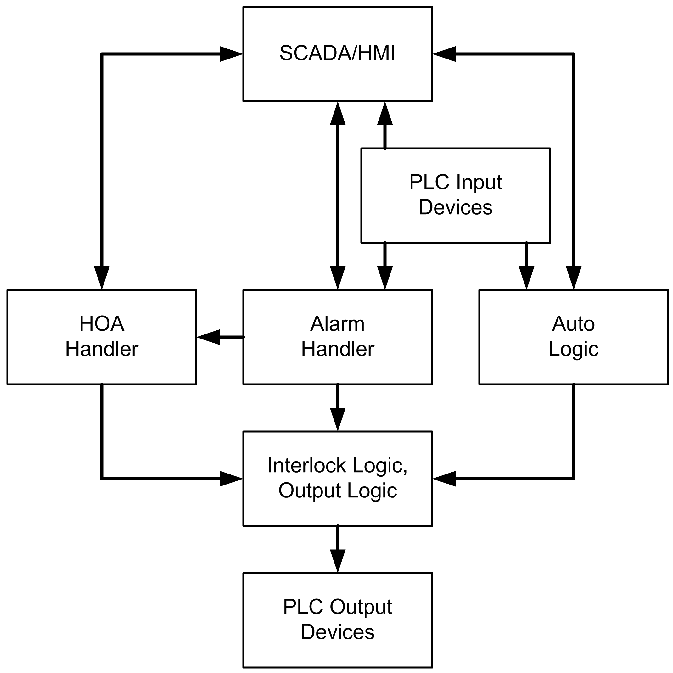
Figure 2 shows a block diagram of the framework used to implement the old architecture. The old framework uses a subroutine for each type of output device to encapsulate common functionality for that type of device, and a UDT tag to store its state. The auto logic and interlock logic set the value of input bits in the UDT tags for each device, which are then used in the respective subroutines to set output bits in the UDT tags, which are then used to drive the PLC outputs for the output devices. Hand/off/auto and alarm handling are done on an individual basis for each device in its respective subroutine. Alarms are also processed individually using a UDT tag for each alarm and a subroutine.
Figure 3 shows a block diagram of the framework used to implement the new architecture. The new framework handles hand/off/auto and alarming centrally using tables and logic that operates on whole tables rather than individual bits. Auto logic in the new framework stays at a higher level of abstraction compared to the old framework. For example, one of the bits driven by the new auto logic is set while water should be added to the batch tank for the first water addition step. The output logic uses these bits along with hand/off/auto status bits to drive the PLC outputs for the output devices. Interlock logic is placed on the rung that drives the PLC output so it is easy to find and verify. A significant advantage of the new framework is that troubleshooting is much easier for end users who have modest programming ability because they only need to look at simple ladder logic, as opposed to the old framework where they need to look in subroutines and bits in UDT tags.
4. Case Study: Control System Rewrite
A food production line at a leading food manufacturer was in service and considered to be fully debugged for several years. However, there were some issues with the system. Two batch tanks used to mix a slurry for the final product were unable to keep up with the line speed because the batching sequences of the tanks had unnecessary interlocks. Batching sequences for the tanks and other processes on the line were controlled by software running on a personal computer (PC), which added some delay between steps and would occasionally lock up and halt production. The PLC program was written using sophisticated techniques to take advantage of the advanced PLC capabilities, which made it difficult for electro-mechanical technicians to use the program to troubleshoot problems when the line went down. The manufacturer considered a proposal to rewrite the PLC program to fix these issues. However, it was difficult to justify the cost, because the line was in full production and it was difficult to quantify the benefits of replacing one commissioned program with another. One day during production, the line went down but showed no alarms. The electro-mechanical technicians were not able to troubleshoot the problem and eventually called a plant controls engineer, who could not find the problem either. An outside contractor was called who eventually found the problem, which was an internal bit several subroutines deep in the program that had been set by the brief loss of an emergency stop input and had to be cleared in the program to start the line. The downtime spanned two shifts, and the incident was used to justify rewriting the PLC program.
The new program uses a software architecture and framework that favors simplicity, and considers that the end user will use the program as a troubleshooting tool. A complete discussion of the architecture and framework differences between the old and new programs is beyond the scope of this paper. This section describes a few key differences between the two programs.
4.1. Control of Output Devices
This section discusses how logic for the control of output devices such as motors and valves is implemented in each program.
4.1.1. Original Program
The original program takes advantage of user-defined data types (UDTs) and subroutines. Each device class (two-way valve, reversing motor starter, variable frequency drive, etc.) has a corresponding UDT and an associated subroutine. A data tag of the appropriate UDT is created for each device to represent its state. Logic that is common to all devices in a class is contained in the device subroutine. Control of the device is implemented as follows:
The input members in the data tag are assigned appropriate values.
The device subroutine is called, passing the data tag as a parameter.
The output members in the data tag are assigned to real-world outputs.
As an example, consider the two-way valve V1000. Two-way valves use the V_2WAY UDT, shown in
Table 1, and the V_2WAY_SBR subroutine. Valve V1000 has a data tag named V1000 of type V_2WAY.
Figure 4 shows a simplified example of how the control of V1000 is implemented. First, the real-world inputs for the valve position switches are assigned to V1000.ZSO and V1000.ZSC. Next, the V_2WAY_SBR subroutine is called, passing V1000 as an input parameter. The subroutine processes the input members of V1000 and assigns values to the output members according to the common control logic for a two-way valve. Finally, V1000.FYO, which is assigned a value in the subroutine, is assigned to the real-world output for the solenoid that actuates V1000. In the actual program, more logic is required to set up the other input members.
4.1.2. New Program
In the new program, a much simpler approach is taken.
Figure 5 shows ladder logic that is typical for discrete outputs. The real-world output is programmed on the second rung. In general, devices with hand/off/auto control are energized if either (a) the device is in auto mode and the auto logic is trying to energize it; or (b) the device is in hand mode. This is reflected by the contacts on the left side of the rung. If there are any interlocks that must be met to energize the output, they are added in the series in the middle of the rung so they inhibit the output regardless of mode. The auto logic for the device (i.e., the “auto command”) is programmed on a single rung above the output rung.
In addition to the real-world output, the output rung has two other coils that are programmed in parallel so they all have the same value. The first is the mapped output bit and the second is an alias bit. Real-world output bits are mapped to a single table primarily so they can be read efficiently by the HMI. The name of the alias bit is the tag name of the device. Device tag names are indicated on the HMI screens, the piping and instrumentation diagrams (P&IDs), and the physical devices themselves, so it is convenient to use the alias throughout the program because it is easier to remember than the output address.
The example given in
Figure 5 is the control logic for the water inlet valve on batch tank #1 (BT1). Opening the water valve when the dry ingredient slide gate is open may allow some water to get into the dry line and cause problems. The auto logic accounts for this, but the dry inlet slide gate closed prox is added as an interlock to prevent it from happening in hand mode. There are three phases in the batching operation where water is added to the batch tank. This can be seen clearly in the logic for the auto command.
The logic for outputs is written with the end-user in mind. In this example, if the valve does not open or close as expected these two rungs are an excellent troubleshooting tool. It is easy to find these rungs using a cross-reference or a search for V1000. The state of each contact and coil is clearly indicated in color when online with the PLC, so it is quickly obvious if the output is energized. If not, it is easy to see why it is not. The logic on the auto command rung is written to be simple, so it almost reads the way a person would describe the automatic operation of the device. In this case, it almost reads “in auto mode, the inlet valve opens when the batching operation is in the first, second, or third add water phases.” If more detail is desired, the logic for the bits on the auto command rung can be found by a quick cross-reference.
There are several advantages to the simple, end-user-friendly approach of the new program versus the more sophisticated, developer-oriented approach of the original program:
In the original program, the user cannot see the state of contacts and coils in the subroutine for a particular device (note that this problem can be avoided in newer PLC revisions by using an Add-On instruction instead of a UDT and a subroutine. Add-On instructions were not available when the original program was written.) This makes troubleshooting the original program very difficult for many technicians and inconvenient even for experienced developers who are not familiar with the architecture. Troubleshooting the new program requires only the most basic PLC skills.
In the original program, a subroutine for a class of devices contains logic for every feature or mode of operation that may be used. All of the logic is processed by the PLC for each device when the subroutine is called, even if it is not needed. In the new program, only the logic that is needed is included and processed.
In the original program, all devices in a class have exactly the same logic. This is usually an advantage, but if one device must operate slightly differently than the others either (a) a new subroutine must be created with slightly different logic; or (b) the UDT must be expanded to parameterize the change and the subroutine must be modified to process the new parameter. This is not an issue in the new program.
4.2. Hand/Off/Auto Control of Devices
Operators can select hand, off, or auto mode for most devices in the production line. A device in hand or off mode is energized or de-energized, respectively. Assuming interlocks are satisfied, this effectively forces the device on or off. A device in auto mode is energized or de-energized automatically without operator intervention, allowing the PLC to control the device according to the auto logic. This section discusses how hand/off/auto control of output devices is implemented in each program.
4.2.1. Original Program
In the original program, the UDT for each type of device includes a member named HOA (hand/off/auto status) of type DINT (32-bit integer). A value of zero indicates off mode, one indicates auto mode, and two indicates hand mode. When a mode is selected from the Human-Machine Interface (HMI) for a device, the appropriate value is written to a table in the PLC. The subroutine for the device determines the new mode based on the value in the table and the value of other bits such as FOH, the force off mode bit, and INHA, the inhibit auto mode bit. The new mode is then written back to the table, possibly overwriting the value from the HMI, so the HMI can display the actual mode. The appropriate element in the table is determined by the IDX (data table index) member of the data tag for the device.
4.2.2. New Program
In the new program, there are several tables of bits: request hand mode, in hand mode, request off mode, in off mode, request auto mode, and in auto mode. When a mode is selected from the HMI, the appropriate request bit is set. A centralized handler processes all the hand, off, and auto requests, compares them to the corresponding in hand, in off, and in auto status bits, and updates the status bits accordingly. Forced modes, such as forcing an alarmed device into off mode, is implemented by setting the request off mode bit every scan that the alarm is active. If there are requests for multiple modes for the same device, which can result from multiple HMI stations and/or from a forced mode, only one mode status bit is set. The order of priority is off mode, auto mode, then hand mode. If a device is in off mode, the handler ensures that the auto mode and hand mode status bits are off, so the off mode status bit does not need to appear in the output rung, as can be seen in
Figure 5.
There are several advantages to the centralized approach of the new program over the device approach of the original program:
Less memory is needed. The original program uses two 32-bit DINTs per device, one in the data tag for the device and the other in the table that interfaces to the HMI. The new program uses only six bits for each device, packed efficiently in tables.
In the original program, the hand/off/auto logic is in the same subroutine as the logic for the output. In the new program, the handler is in a routine separate from the output logic, so the end-user does not have to look at it while troubleshooting outputs.
In the original program, logic for processing hand/off/auto requests is duplicated in each subroutine for the different device classes. If a change is required, it must be duplicated in each subroutine. There is only one copy of the logic for processing requests in the new program.
The original program processes one device at a time. The new program processes the tables word by word, so it executes much faster.
4.3. Alarm Handling
This section discusses how alarm handling is implemented in each program.
4.3.1. Original Program
In the original program, each alarm is represented by a data tag of the user-defined data type Alrm. The Alrm UDT is shown in
Table 2. Alarm handling is implemented as follows:
The CONDITION bit of the alarm tag is programmed.
The Z_ALRMD subroutine is called, passing the alarm tag as an input parameter.
For example, the CONDITION bit for a motor alarm might be programmed to be on if the motor run output is on and the motor running input is off. The subroutine uses the CONDITION bit to enable a timer defined by the TIMER member. If the timer times out, the subroutine sets the ALM bit. The subroutine handles alarm acknowledgement and silencing, and determines if there are any audible alarms or alarms that should light the alarm beacon.
Most of the alarms in the original program are device alarms, such as when a motor fails to run or a valve fails to move into position. The UDTs for devices include a member named DFA of type Alrm. The subroutine for each device class includes logic to set the DFA.CONDITION bit and call the Z_ALRMD subroutine.
4.3.2. New Program
In the new program, there is a table of alarm bits. Alarm bits are latched using logic similar to that shown in
Figure 6 for the V1000 failure to open alarm. Logic for latching alarms is grouped by area into routines so it is easy to browse. A centralized alarm handler processes alarm acknowledgement and alarm silence inputs.
There are several advantages to the simple alarm detection logic with a centralized handling approach of the new program over the device approach of the original program:
In the original program, the condition logic for device alarms is located in the subroutine for the device class. This makes troubleshooting alarms difficult for the same reasons why it is difficult to troubleshoot output logic. In the new program, alarm logic is easy to find and view the state of contact and coils online.
The original program processes one alarm at a time. The new program processes the condition logic without the overhead of a subroutine call, and processes the alarm table for acknowledgement and silence handling word by word, so it executes much faster.
5. Results
The plant manager provided production data for ten full months prior to the conversion and ten full months after the conversion. The plant defines production efficiency as the number of cases of products produced per production hour divided by the number of cases per hour that the system was designed to produce. For example, if the line was designed to produce 1000 cases per hour and an average of 900 cases are produced per hour, the efficiency is 90%. The average efficiency for the ten full months after the conversion was 6.1% higher than the average efficiency for the ten full months immediately prior to the conversion.
The cost of rewriting the PLC program was recovered through increased efficiency after just a few months, and continues to pay dividends every production run going forward. Other quantifiable improvements are as follows:
The scan time of the program went from approximately 220 ms down to 18 ms. The new program is an order of magnitude faster than the original program for several reasons. The overhead from calling subroutines for each device and each alarm is eliminated. Hand/off/auto requests and status are processed centrally as a table rather than individually by device. One benefit is that PID loops are updated much faster, which is important for several speed, flow, pressure, and continuous blending loops in the production line. Another benefit is better response time, which allows faster and more consistent reaction to inputs.
The memory footprint of the PLC program is about 14% smaller. Memory size was reduced even though batch execution logic and additional recipe related logic were moved into the PLC. The original program had common logic in a single subroutine, but the memory savings were more than offset by the memory requirements of the UDT-based data tags for each device. The benefit is that more memory is available for expansion even though more functionality has been added to the PLC.
6. Discussion
There are a number benefits of the new program that cannot be easily quantified and are more subjective:
The overall control system is simpler. All batching control was moved into the PLC, eliminating a batch execution package that was running on a separate workstation. The original batching system would sometimes run slowly, and would often lock up or get stuck in a phase. The benefit of the new system is that a significant source of downtime and wasted product has been eliminated. Recipe management interactions were migrated to an existing plant-wide system, eliminating a piece of custom software for recipe management. The original custom software lacked important functionality and could not be modified because the source code was not provided to the manufacturer. The benefit is that the new system leverages the existing plant-wide system and has no proprietary code.
The PLC program is simpler. There is no indexed addressing except in hand/off/auto and alarm handler code, which does not need to be seen by the end-user. Subroutines are only used to organize code, none are called more than once per scan, and none are called with parameters. Logic for outputs and alarms is simple and the state can be viewed easily when online with the PLC. The benefit is that the technicians who support the line have a much easier time troubleshooting problems. The program was also easy to startup, producing more consistent products and exceeding target production rates on the first day.
The PLC program is better organized for troubleshooting. Each area of the line has three separate program routines: auto logic, output logic as in
Figure 5, and alarm logic as in
Figure 6. The benefit is that all three routines can be viewed at the same time, and logic can be browsed easily without the distraction of hand/off/auto and alarm handling code. This, in combination with simple logic, makes troubleshooting easier.
The HMI shows operators more information about the batching phases. Each phase of each batching operation is shown on the HMI so the operators know how the system works. The current phase and the state of each condition required to advance to the next phase are also indicated. If necessary, it is possible to manually advance phases or reset the operation from the HMI. The benefit is that operators always know what the system is doing and what it is waiting for. They also have manual control of each operation so they can recover easily from problems such as power failures without loss of time or product.
The original control system was developed using a sound, legitimate programming philosophy. Good arguments can be made in support of each element of the original architecture. The new control system follows a different, but also sound and legitimate philosophy. The decision of which philosophy to follow, or combination of the two, should take into account how the program will be used and the skill level of the people who will use it. Regardless of how the results are interpreted, this case study suggests the following:
7. Suggestions for Research
The purpose of this paper is not to claim the best way to write a PLC program. The purpose is to show that the software architecture of PLC programs makes a difference in production efficiency, and is deserving of further study. Some questions to guide this research are as follows:
What software architecture(s) should be used for PLC programs now and in the future?
How can the increasing power and sophistication of PLCs be exploited while keeping programs simple enough for infrequent users to use them for troubleshooting?
What new troubleshooting tools and techniques can be developed to reduce or eliminate the need for the end-user to use the PLC program?
Some suggested topics for further research include the following:
Framework for PLC Software.
A framework for PLC programming is an implementation shell of the software architecture. It provides common functionality, such as hand/off/auto control and alarm handling, so that the programmer does not have to “reinvent the wheel.” Framework also speeds up development and leads to code that is more scalable and robust. The case study suggests that portions of the framework that the end-user will see should favor simplicity, while portions that will only be seen by developers can take advantage of the increasing sophistication and power of current and future PLC generations. Developments in other suggested areas may influence framework design. For example, improved troubleshooting tools may eliminate the need for end-users to view the program, automatic code generation may benefit from specific framework support, etc.
Design Patterns for PLC Software.
Design patterns recognize recurring programming challenges and suggest a common way of handling them. Simple patterns, such as standard PID control of an analog output, may be handled sufficiently using existing templates. Research to identify more complex patterns is suggested, followed by development of well-thought solutions. For example, multiple PLCs controlling different equipment on a production line, which may be programmed by different people, often need to share command and status data to interoperate efficiently.
Simulation of PLC-Based Control Systems.
Simulations of control systems can be used for initial testing of control programs to speed commissioning and startup. The simulations can be used after startup to train operators off-line and to try alternate control strategies. Simulation packages are available commercially. However, research in this area could lead to open source methods to develop simulations, which would reduce the cost and increase the availability of useful simulators.
Automatic Generation of PLC Code from High Level Specifications.
When a framework is developed, much of the customization code could be generated automatically. For example, an input/output (I/O) list could be used to generate tags, comments and output logic similar to that shown in
Figure 5. Steps in a sequence, which are easily described as a finite state machine, can be converted to PLC logic. One overall goal of this research could be to generate as much code as possible from a specification of the process. The specification could be largely derived from mechanical and electrical drawings of the system that are typically produced already. This could be extended to automatically generate a process simulator.
Verification and Validation of PLC-Based Control Systems.
A framework and a process simulator could help enable automatic verification and validation of PLC programs. If the framework includes a standard interface to the HMI software, operator actions could be simulated to verify the correct response of the control system. Unit testing, common in general software application develpoment, could be applied to PLC software.
Troubleshooting Tools and Techniques for End-Users.
The case study exposed the need to keep PLC software simple so end-users could use it as a troubleshooting tool. This is at odds with the desire of many developers to take advantage of the increasing sophistication of PLCs. Machine learning techniques could be applied for fault diagnosis. A simpler approach for the near term could involve automatic generation of HMI screens that provide the information the end-user would normally look for in the PLC code.
Integration of PLC Software and HMI Development.
PLC programming and HMI development of HMI screens are often done by different people. In an effective system, the PLC code and HMI must work well together to get the most benefit from each. It would be beneficial to approach most of the suggested research topics from this perspective. For example, a high level specification could be used to generate integrated PLC code and corresponding HMI screens, design patterns could account for operator interaction with a mechanical system, simulators could simulate operator actions as well as the process, etc.
8. Conclusions
As PLCs and the skills of people who program them become more sophisticated, the natural inclination is often to use a programming style oriented more toward the developer than the end-user. In many PLC-controlled production lines, however, the programs are used for troubleshooting by people with modest programming ability. The original program described in this paper uses more sophisticated techniques, while the new program favors a much simpler approach. This simple approach led to a program with fewer issues that cause downtime. The simpler program is also a better troubleshooting tool, reducing downtime when problems do occur. This paper shows that PLC program architecture can have a significant impact on production efficiency, and suggests topics for further research in this area.


