Communication

Study on Performance Improvement through Reducing Axial Force of Ferrite Double-Layer Spoke-Type Permanent Magnet Synchronous Motor with Core Skew †

1
Department of Electrical Engineering, Gachon University, Seongnam 13120, Republic of Korea
2
Department of Electrical Engineering, Michigan State University, East Lansing, MI 48824, USA
3
Department of Electrical Engineering, Hanyang University, Seoul 04763, Republic of Korea
4
Department of Electrical Engineering, Yuhan University, Gyeongin-ro 590, Bucheon-si 14780, Republic of Korea
*
Author to whom correspondence should be addressed.
This paper is an extended version of our paper published in Nam, D.; Lee, K.; Pyo, H.; Jeong, M.; Kim, W. A Study on Performance Improvement by Reducing Axial Force of Double-Layer Spoke-type PMSM with Core Skew Structure. In Proceedings of the 2022 IEEE 20th Biennial Conference on Electromagnetic Field Computation (CEFC), Denver, CO, USA, 2022, pp. 1–2, https://doi.org/10.1109/CEFC55061.2022.9940666.
Machines 2024, 12(4), 280; https://doi.org/10.3390/machines12040280
Submission received: 10 February 2024 / Revised: 14 March 2024 / Accepted: 22 March 2024 / Published: 22 April 2024
(This article belongs to the Special Issue Advances and Trends in PM-Free or Rare-Earth-Free PM Motors)

Abstract

:
Recently, due to the price fluctuation and supply instability of rare earth mineral resources, there has been a lot of development of electric motors using non-rare-earth permanent magnets. As a result, motors using Dy-free permanent magnets and ferrite permanent magnets are being researched, and, in particular, ferrite permanent magnets often utilize spoke-type structures, which are magnetic flux concentrators, to compensate for their low coercivity and residual flux density. However, in general, spoke-type PMSMs do not use much reluctance torque, so double-layer spoke-type PMSMs have been studied for their more efficient design. Unlike general spoke-type PMSMs, double-layer spoke-type PMSMs can utilize high reluctance torque by increasing the difference between d-axis and q-axis reluctance. However, as the difference in magnetic resistance increases, vibration and noise are generated, which adversely affects the mechanical part and shortens the life of the motor. Although this problem seemed to be solved by applying core skew in the previous study, it was confirmed that the axial force caused by the axial leakage flux occurred in the maximum torque per ampere (MTPA) control section and the torque ripple was increased. Therefore, in this paper, a model that can apply symmetrical core skew and reduce axial force is proposed. First, the causes of the axial force generated in previous studies were analyzed. Based on the analysis of these causes, a new symmetrical core skew structure was proposed, and its justification was verified through FEA.

1. Introduction

1.1. Summary

Due to the unstable supply of rare earth minerals, the research and development of spoke-type permanent magnet synchronous motors (PMSMs) using ferrite permanent magnets has been actively pursued [1,2]. However, spoke-type motors suffer from the disadvantage of not being able to use large amounts of reluctance torque. Double-layer spoke-type PMSMs were designed to compensate for this.
This double-layer spoke-type PMSM can concentrate magnetic flux using a ferrite permanent magnet instead of a rare-earth-type permanent magnet similar to a conventional spoke-type motor. In addition, the conventional spoke-type permanent magnet motor does not utilize the reluctance torque properly because the d-axis and q-axis magnetoresistance are not large, but the double-layer spoke-type PMSM divides each permanent magnet into two. By inserting an iron core to reduce the q-axis magnetoresistance, the difference with the d-axis magnetoresistance is increased, and a high reluctance torque can be used [3].
However, as the magnetoresistance difference between the d-axis and the q-axis increases, factors such as cogging torque and torque ripple increase, which adversely affects the operation of the motor [4,5,6]. This soon causes performance degradation, such as vibration, noise, and poor position and speed control. In order to compensate for this, in general, the method of applying a skew structure is most widely used [7,8], but it is also difficult to manufacture and sometimes increases the torque ripple, so it is not a good solution.
To solve this problem, a new concept of skew, core skew, was applied in [9]. In the case of conventional skew, step skew is usually applied during the design and manufacturing steps, but in this case, even when inserting permanent magnets in the axial direction, the permanent magnets are divided by the number of steps, which is not good for manufacturability. The core skew proposed in [9] is shown in Figure 1. Core skew means that permanent magnets are inserted as a single bar-type without dividing them, and only the shape of the part adjacent to the air gap of the rotor core is changed to give the same effect as if the air gap flux density was skewed. As a result of this effect, cogging torque, no-load THD, and torque ripple in the high-speed operation area are significantly reduced, and manufacturability is more favorable than with the existing skew method.
However, it was confirmed that this core skew also increases the torque ripple in the low-speed operation area. There are many factors that affect the torque ripple, but as shown in Figure 2, it can be confirmed that the axial force has some effect on the torque ripple. In addition, the axial force continuously transmits a mechanical load to the bearing connected to the motor, causing vibration and noise and shortening the life of the motor [10]. Since the target model of this paper uses sensorless control, the torque ripple that affects the back electromotive force used for detection must be reduced.
In this paper, the cause of the increased torque ripple at the low-speed operation point was analyzed as the axial force shown in Figure 2; to reduce it, a symmetrical core skew shape was proposed, the optimal design was carried out in two dimensions using the finite element analysis (FEA) program Maxwell, and then it was verified through 3D FEA.

1.2. Conventional Model Specifications

Washing machine motors, the target model for this paper, are categorized into two types: belt-type motors and direct-drive types. Direct-drive motors are typically mounted on the back of drum-type washing machines and operate directly, while belt-type motors operate by connecting a belt to the shaft of the motor. Belt-type motors are used in the most common types of washing machines, and they are the ones that are the subject of this thesis. Model specifications are shown in Figure 3 and Table 1.

2. Equation and Analysis of Axial Force

2.1. Equation for Axial Force

The torque mechanism of the permanent magnet synchronous motor is generated by Equation (1).
d F = J × B
In the above equation, d F is the force density, J is the current density, B is the the magnetic flux density, and the force can be obtained by integrating d F with the volume.
However, in general, since the permanent magnet synchronous motor has a cylindrical shape, it is necessary to obtain the force of each direction component with respect to the cylindrical coordinate system. In the electromagnetic field analysis based on finite element analysis (FEA), the torque equation is calculated using the Maxwell stress tensor method and is defined by Equations (2) and (3) [11].
F = V · T d v = S T · n d s
T i j = B i B j μ 0 δ i j B 2 2 μ 0
T expressed in the above equation is the Maxwell stress tensor; B is the magnetic flux density; μ 0 is the magnetic permeability of the vacuum; i and j are the components of the coordinate system; and δ i j is Kronecker delta, which has a value of 1 when i and j are the same and, if it is a different value, i and j become 0. Since this paper deals with spoke-type PMSMs, they will be dealt with in a cylindrical coordinate system. The Maxwell stress tensor matrix in a cylindrical coordinate system is shown in Equation (4).
T = 1 μ 0 B r 2 B θ 2 B z 2 2 B r B θ B r B z B θ B r B θ 2 B r 2 B z 2 2 B θ B z B z B r B z B θ B z 2 B r 2 B θ 2 2
F r = 1 μ 0 S B r B z d s
F θ = 1 μ 0 S B θ B z d s
F z = 1 μ 0 S B z 2 B r 2 B θ 2 2 d s
Thus, Equations (5)–(7) express the force using a cylindrical coordinate system. In the above formula, r , θ , and z are the direction components in the radial, tangential, and axial directions, respectively. In general, the torque is calculated by Equation (6), which is the force of the tangential component, and the axial force is calculated by Equation (7).

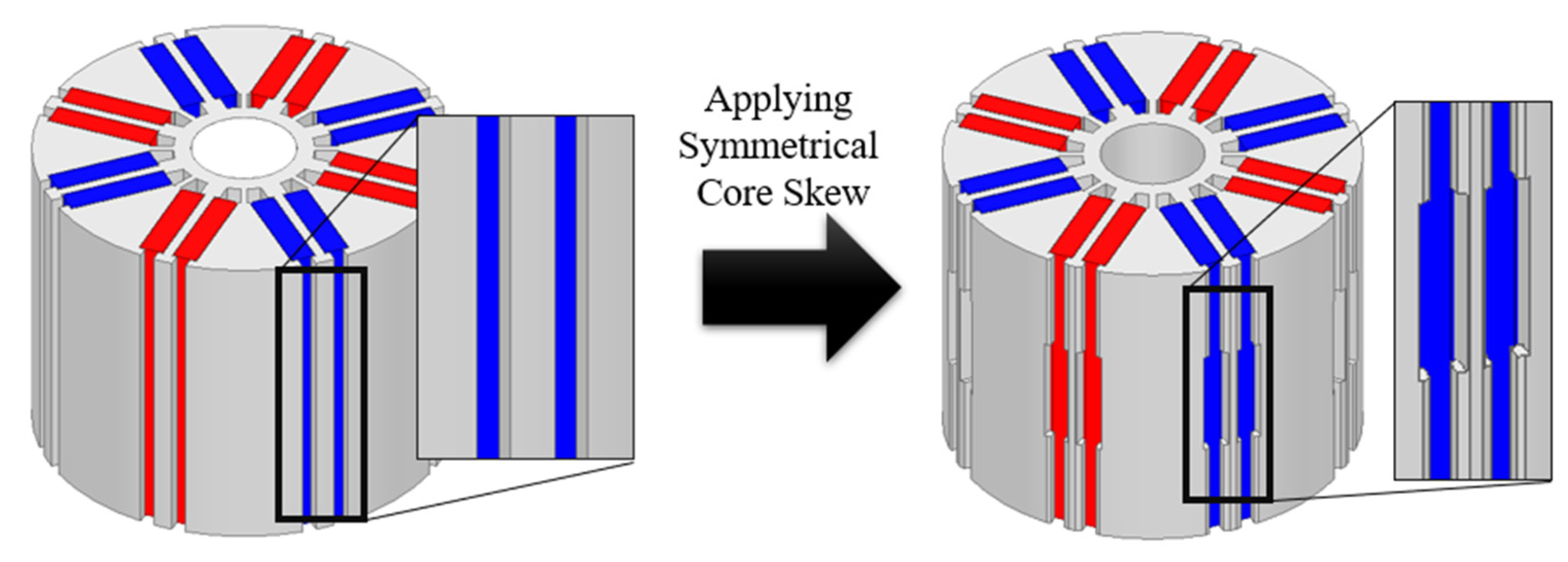
2.2. Analysis of the Cause of Core Skew

Figure 4 shows the conventional model without core skew and the model with core skew, and Table 2 shows the comparison of torque ripple and axial force.
First, the axial force is generated by Lorentz’s law as the leakage magnetic flux in the axial direction is linked to the end turn of the stator. At this time, since the core skew model has an asymmetric shape, the leakage magnetic flux in the axial direction is also asymmetrically linked to the end turn and axial force is generated as shown in Table 2.
Figure 5 shows the axial force waveforms of the conventional model and the core skew model under a washing load (580 rpm). According to the research results of [12], in the case of the conventional model, the axial force converges to 0 because it is canceled by the symmetry of the leakage flux in the axial direction. On the other hand, in the case of the model to which the core skew is applied, the axial force is not offset by the asymmetry of the leakage magnetic flux in the axial direction and is generated in one direction as shown in Figure 6.
In [9], it can be seen that the torque ripple is reduced by applying core skew in the high-speed region. This is because the axial leakage flux is also suppressed because the weak flux control is applied in the high-speed region, so the axial force is not as high as in the low-speed region.
In the case of a general model without skew, such an axial force does not occur, but if the axial force is not offset and occurs in one direction, the torque ripple increases, which in turn increases vibration and noise, and adversely affects mechanical parts such as bearings, which can shorten the life of the motor.
Therefore, a symmetrical core skew model with the structure of Figure 7 as a reference is proposed in order to reduce the axial force of the core skew model. The proposed model should be divided into Stack No. 1 and Stack No. 2 by stacking two different models in the axial direction. When manufacturing, the model can be produced by counter-punching the same mold, and the existing production method and equipment can be maintained as is.

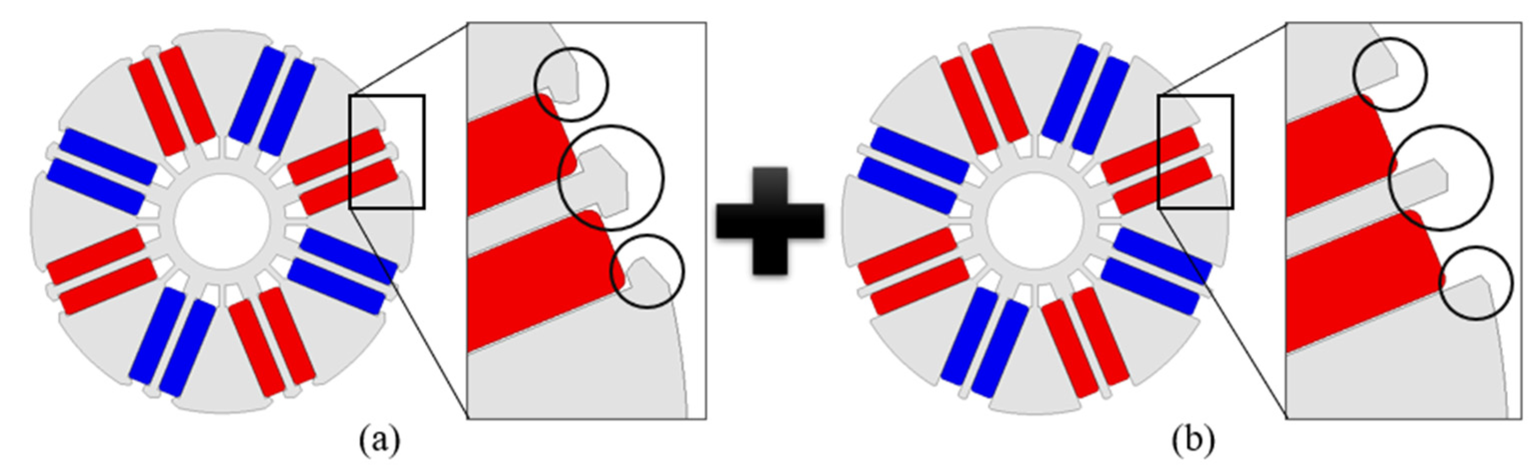
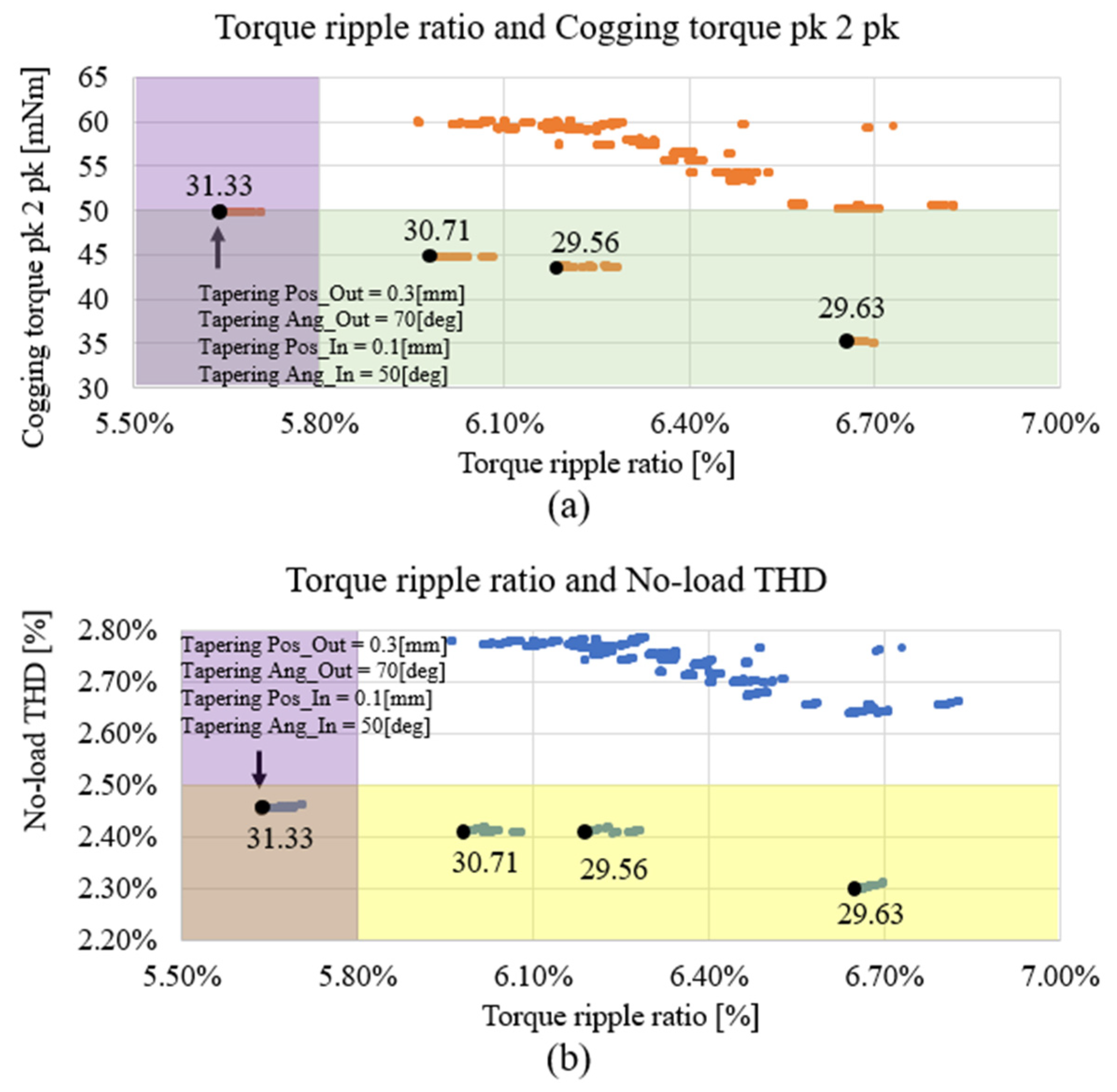
3. Geometric Variables and Their Effects on 2D FEA

To select the optimal model of symmetrical core skew, an FEA (finite element analysis) was performed by setting variables for tapering in the fixed part of the permanent magnet.
Tapering is an important design parameter because it is used to make the vacancy flux density of the motor sinusoidal, which in turn is related to cogging torque, torque ripple, THD, etc.
In order to analyze the axial force, 3D FEA should be performed, but because it takes a long time to analyze, the optimal model for torque ripple, cogging torque, and no-load THD is selected through two-dimensional DOE (Design of Experiments); then, three-dimensional analysis was performed.
Figure 8 and Table 3 describe the setting of each variable. In Table 4, P O is the variable for the position to modify the angle of tapering on the outside of the permanent magnet fixing bar, and A O is the variable for the angle. Also, P I is a variable for the position to modify the angle of tapering inside the permanent magnet fixing bar, and A I is a variable for the angle.
As shown in Figure 8a, the variables for tapering were applied to both the outside and inside of the permanent magnet fixing part. In Figure 8b, 2D FEA was performed on one variable for the outer side. The variables for the outer side shown in Figure 8a,b have a common variable, and each variable is set to taper to the minimum that can fix the permanent magnet. Also, recognizing that it is a three-step process, 2D FEA was performed by applying 2/3 of the stacking length in Figure 8a and 1/3 of the stacking length in Figure 8b, and the results were calculated by summing the results.
Figure 9 shows the results of 2D FEA for changes in the degree of tapering. For the optimal model selection criteria, the highest total weight score was selected using the total sum of the weight scores in Table 4 [13].
In Table 4, X ( c ) is the result of the conventional model, and Y ( t ) is the result of the torque ripple ratio, cogging torque pk 2 pk and no-load THD according to the variables set in Table 3. Each significant factor is the importance assigned to torque ripple, cogging torque pk 2 pk, and no-load THD. Torque ripple, which is most important in real-world load operation, receives the highest weight. Set S_T to 50 and S_C and S_H to 25 each, so that the total sum is 100, which is the value finally calculated by the weighted score formula.
The model with the highest total weight score is shown in Figure 9 with P O = 0.3 mm, A O = 70 deg, P I = 0.1 mm, and A I = 50 deg. Accordingly, the model with the highest weight total score of 31.33 was selected.
Table 5 is the result of comparing the model selected through Figure 9 and Table 4, the conventional model, and the core skew model, respectively.
The torque ripple of the symmetrical core skew model was reduced compared to the conventional model and the core skew model. This can be analyzed through the torque spectrum and the torque phase spectrum provided in Figure 10 and Figure 11. For the general model without skew, the spectrum of torque phase is the same, but for the proposed model with symmetrical core skew, as shown in Figure 11, it can be seen that the phase of the 6th and 12th harmonics of Stack No. 1 and Stack No. 2 are opposite to each other and cancel each other out, causing the torque ripple to decrease. This is because the waveform of the torque is six cycles in one electrical angle, which is determined by the interaction of the fundamental wave of the motor voltage with the fifth and seventh harmonics.

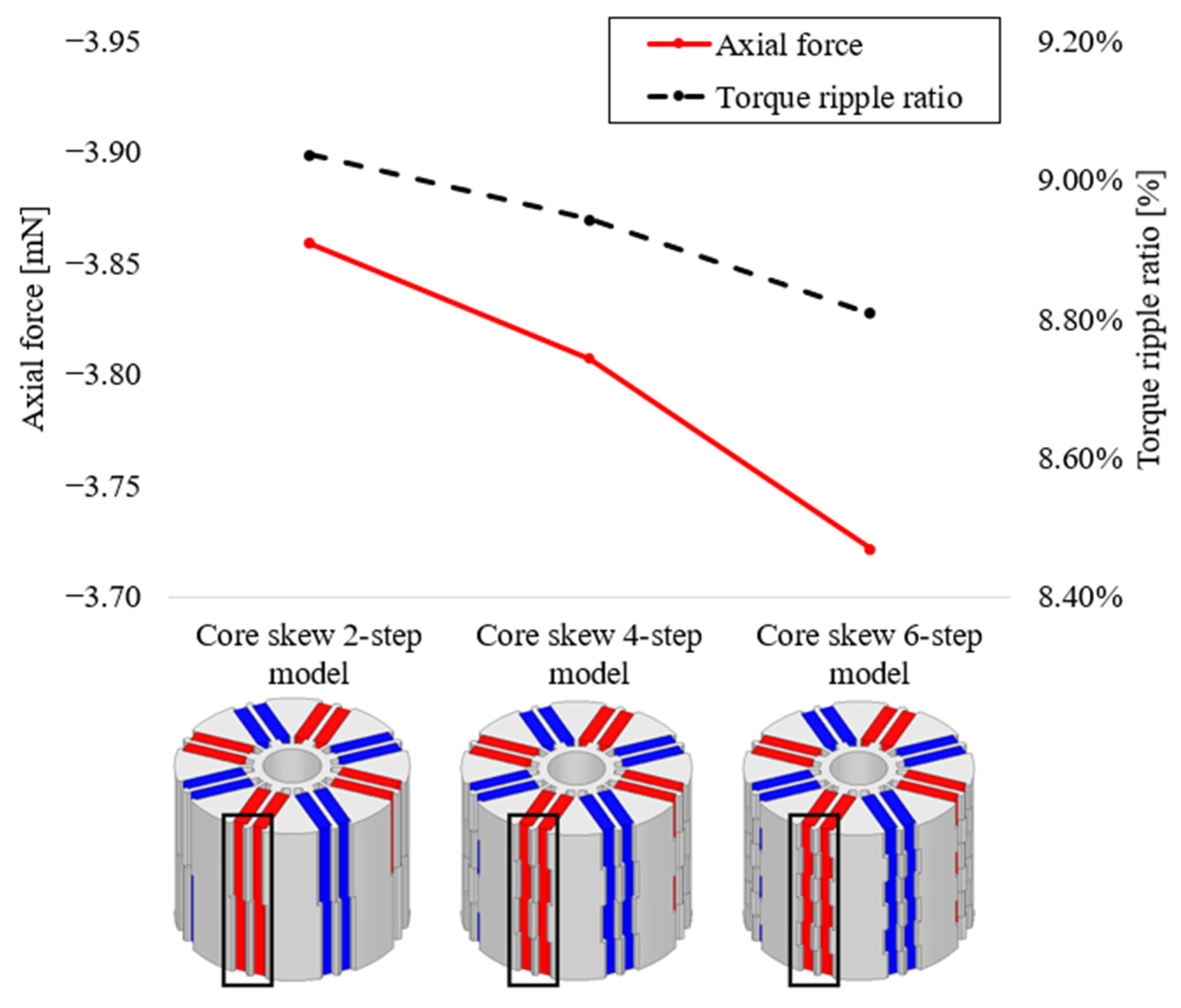
4. Three-Dimensional FEA Based on Several Modeling Steps

The optimistic model selected through 2D FEA in the previous section was modeled as shown in Figure 12 to proceed with 3D FEA according to each step. The modeling of the symmetrical core skew was considered for models using the three-step to seven-step methods and was organized in the order of Stack No. 1–Stack No. 2–Stack No. 1, with Stack No. 1 geometry at the top and bottom. And Table 6 shows the results of 3D FEA.
It was confirmed that the axial force of the symmetrical core skew model was significantly reduced compared to the core skew model, and the torque ripple ratio was also reduced by about 2%p.
Figure 13, Figure 14 and Figure 15 are the results of comparing the waveform and spectra of torque and axial force based on the comparison between the core skew four-step model selected in [9] and the symmetrical core skew five-step model with the lowest axial force and lowest torque ripple in this paper.
As shown in Figure 14, the results are reduced compared to those with the core skew four-step model. Therefore, the waveform of the torque is also reduced. Since it has a symmetrical structure, the axial force is reduced, and the result can be seen in Figure 15.

5. Conclusions

This paper aims to suppress the torque ripple caused by the axial force which is not improved in the core skew structure. As mentioned in [9], in a double-layer spoke-type PMSM, the general spoke-type PMSM has the advantage of being able to use more reluctance torque, but the more reluctance torque is used, the more cogging torque, torque ripple, THD, etc., which can cause vibration and noise, increase, and a structure called core skew is proposed as a way to reduce it. However, at low speeds, torque ripple was found to increase.
In this paper, we analyzed how, due to the axial asymmetry, the axial leakage magnetic flux also became asymmetrical, and the axial Lorentzian force caused by the asymmetrical leakage magnetic flux linkage at the end turns could not be offset. To solve these problems, a symmetrical core skew model is proposed in this paper. The symmetrical core skew model divides the rotor core into Stack No. 1 and Stack No. 2 to design the respective shapes, just like the conventional core skew. However, in the case of the conventional core skew, Stack No. 1 and Stack No. 2 are reversed in the core part that holds the permanent magnet, and an even number of steps are applied. However, in the proposed symmetrical core skew, symmetry is applied when looking at the rotor core from the air gap, an odd number of steps are applied, and the axial Lorentz force can be reduced due to the symmetry of the axial leakage flux. The torque ripple was reduced by reducing the axial Lorentz force, and through further optimal design in 2D FEA, the torque ripple was minimized by combining Stack No. 1 and Stack No. 2 so that the torque phase spectrum could be offset as much as possible. In addition, the continuous load transmitted to the bearings connected to the shaft of the motor can be reduced, which has the effect of extending the life of the motor.
This suggests a direction for further development of the magnetic flux concentration-type motor structure, as research on non-rare-earth permanent magnet synchronous motors has been actively conducted recently. In order to utilize the reluctance torque in the extant magnetic flux concentration-type shape, a double-layer spoke-type shape was proposed, and core skew was suggested as a way to reduce vibration, noise, and factors that may adversely affect mechanical parts. The core skew structure has the potential to propose various shapes and can be applied as a specialized form for each application. Therefore, this design method is expected to have a good influence on the overall motor industry.

Author Contributions

Conceptualization, W.-H.K. and J.-J.L.; methodology, D.-W.N.; software, D.-W.N.; validation, D.-W.N.; formal analysis, D.-W.N.; investigation, D.-W.N.; resources, D.-W.N.; data curation, D.-W.N.; writing—original draft preparation, D.-W.N. and K.L.; writing—review and editing, D.-W.N. and K.L.; visualization, S.-W.S.; supervision, W.-H.K. All authors have read and agreed to the published version of the manuscript.

Funding

This work was supported by a National Research Foundation of Korea (NRF) grant funded by the Korean government (MSIT) (No. 2021R1F1A1061592) and in part by the Korea Electric Power Corporation (grant number: R22XO02-02).

Data Availability Statement

Data are contained within the article.

Conflicts of Interest

The authors declare no conflicts of interest.

References

  1. Dorrell, D.G.; Hsieh, M.-F.; Knight, A.M. Alternative rotor designs for high performance brushless permanent magnet machines for hybrid electric vehicles. IEEE Trans. Magn. 2012, 48, 835–838. [Google Scholar] [CrossRef]
  2. Rahman, M.M.; Kim, K.-T.; Hur, J. Design and optimization of neodymium-free SPOKE-type motor with segmented wing-shaped PM. IEEE Trans. Magn. 2014, 50, 7021404. [Google Scholar] [CrossRef]
  3. Kim, S.I.; Park, S.; Park, T.; Cho, J.; Kim, W.; Lim, S. Investigation and experimental verification of a novel spoke-type ferrite-magnet motor for electric-vehicle traction drive applications. IEEE Trans. Ind. Electron. 2014, 61, 5763–5770. [Google Scholar]
  4. Kim, K.-C. A novel method for minimization of cogging torque and torque ripple for interior permanent magnet synchronous motor. IEEE Trans. Magn. 2014, 50, 7019604. [Google Scholar] [CrossRef]
  5. Bianchini, C.; Immovilli, F.; Lorenzani, E.; Bellini, A.; Davoli, M. Review of design solutions for internal permanent-magnet machines cogging torque reduction. IEEE Trans. Magn. 2012, 48, 2685–2693. [Google Scholar] [CrossRef]
  6. Zhu, Z.Q.; Liu, Y.; Howe, D. Minimizing the influence of cogging torque on vibration of PM brushless machines by direct torque control. IEEE Trans. Magn. 2006, 42, 3512–3514. [Google Scholar] [CrossRef]
  7. Zhu, Z.Q.; Howe, D. Influence of design parameters on cogging torque in permanent magnet machines. IEEE Trans. Energy Convers. 2000, 15, 407–412. [Google Scholar] [CrossRef]
  8. Zhu, L.; Jiang, S.Z.; Zhu, Z.Q.; Chan, C.C. Analytical methods for minimizing cogging torque in permanent-magnet machines. IEEE Trans. Magn. 2009, 45, 2023–2031. [Google Scholar] [CrossRef]
  9. Nam, D.-W.; Lee, K.-B.; Kim, W.-H. A study on core skew considering manufacturability of double-layer spoke-type PMSM. Energies 2021, 14, 610. [Google Scholar] [CrossRef]
  10. Yao, B.; Tian, Z.; Zhan, X.; Li, C.; Yu, H. Study on Rotor-Bearing System Vibration of Downhole Turbine Generator under Drill-String Excitation. Energies 2024, 17, 1176. [Google Scholar] [CrossRef]
  11. Meessen, K.J.; Paulides, J.J.H.; Lomonova, E.A. Force calculations in 3-D cylindrical structures using fourier analysis and the maxwell stress tensor. IEEE Trans. Magn. 2013, 49, 536–545. [Google Scholar] [CrossRef]
  12. Park, G.-J.; Kim, Y.-J.; Jung, S.-Y. Design of IPMSM applying v-shape skew considering axial force distribution and performance characteristics according to the rotating direction. IEEE Trans. Appl. Supercond. 2016, 26, 7021404. [Google Scholar] [CrossRef]
  13. Yang, I.-J.; Lee, S.-H.; Jang, I.-S. A process to reduce the electromagnetic vibration by reducing the spatial harmonics of air gap magnetic flux density. IEEE Trans. Magn. 2021, 57, 8103006. [Google Scholar] [CrossRef]
Figure 1. Previously proposed Core Skew model.
Machines 12 00280 g001
Figure 2. Comparison of torque ripple and axial force according to the number of steps.
Machines 12 00280 g002
Figure 3. Conventional model. (a) Stator and rotor; (b) rotor structure.
Machines 12 00280 g003
Figure 4. Conventional model and each step model with core skew applied. (a) Conventional model; (b) core skew 2-step model; (c) core skew 4-step model; (d) core skew 6-step model.
Machines 12 00280 g004
Figure 5. Axial force waveform of conventional model and core skew model.
Machines 12 00280 g005
Figure 6. Axial force of conventional model and core skew model.
Machines 12 00280 g006
Figure 7. Proposed diagram of symmetrical core skew.
Machines 12 00280 g007
Figure 8. Variables for tapering. (a) Stack No. 1; (b) Stack No. 2.
Machines 12 00280 g008
Figure 9. Results of the 2D FEA. (a) Torque ripple ratio and cogging torque according to each variable; (b) Torque ripple ratio and No-load THD according to each variable.
Machines 12 00280 g009
Figure 10. Torque spectrum of Stack No. 1 and Stack No. 2 of symmetrical core skew model.
Machines 12 00280 g010
Figure 11. Torque phase spectrum of Stack No. 1 and Stack No. 2 of symmetrical core skew model.
Machines 12 00280 g011
Figure 12. Three-dimensional model with symmetrical core skew applied: (a) 3-step model; (b) 5-step model; (c) 7-step model.
Machines 12 00280 g012
Figure 13. Torque waveform of each model through 3D FEA.
Machines 12 00280 g013
Figure 14. Torque spectra of each model through 3D FEA.
Machines 12 00280 g014
Figure 15. Axial force comparison of each model through 3D FEA.
Machines 12 00280 g015
Table 1. Specifications of conventional model.
ParameterValueUnit
Stator Outer Diameter134mm
Rotor Outer Diameter60mm
Air Gap0.75mm
Stack Length46mm
Table 2. Comparison of torque ripple and axial force between conventional model and core skew model (580 rpm).
ParameterConventional ModelCore Skew
2-Step Model
Core Skew
4-Step Model
Core Skew
6-Step Model
Unit
torque ripple4.299.048.948.81%
axial force0.2−3.86−3.81−3.72mN
Table 3. Variable setting for tapering.
ParameterRangeStepUnit
PO0.1~0.70.1mm
AO10~7010deg
PI0.1~0.30.1mm
AI10~6010deg
Table 4. Weight score calculation according to the importance of torque ripple, cogging torque, and no-load THD.
ParameterX(c)
(Conventional Model)
Y(t)
(Analysis Model)
Significance FactorWeight Score
torque ripple ratioXT(c) YT(t) ST (XT(c) − YT(t))/
XT(c) × ST
cogging torque pk 2 pkXC(c) YC(t) SC (XC(c) − YC(t))/
XC(c) × SC
no-load THDXH(c) YH(t) SH (XH(c) − YH(t))/
XH(c) × SH
Table 5. Results of the 2D FEA.
ParameterConventional ModelCore Skew ModelSymmetrical
Core Skew Model
Unit
torque1.351.371.37Nm
torque ripple7.688.925.78%
Table 6. Variable set.
ParameterSymmetrical
Core Skew
3-Step Model
Symmetrical
Core Skew
5-Step Model
Symmetrical
Core Skew
7-Step Model
Unit
torque1.341.341.34Nm
torque ripple ratio6.496.376.41%
axial force−0.48−0.23−0.49mN
Disclaimer/Publisher’s Note: The statements, opinions and data contained in all publications are solely those of the individual author(s) and contributor(s) and not of MDPI and/or the editor(s). MDPI and/or the editor(s) disclaim responsibility for any injury to people or property resulting from any ideas, methods, instructions or products referred to in the content.

