Article

Design and Preliminary Evaluation of a Soft Finger Exoskeleton Controlled by Isometric Grip Force

by
Quentin Sanders
1,2,* and
David J. Reinkensmeyer
3,4,5,6
1
Department of Bioengineering, George Mason University, Fairfax, VA 22030, USA
2
Department of Mechanical Engineering, George Mason University, Fairfax, VA 22030, USA
3
Department of Mechanical & Aerospace Engineering, University of California Irvine, Irvine, CA 92697, USA
4
Department of Anatomy and Neurobiology, University of California Irvine, Irvine, CA 92697, USA
5
Department of Biomedical Engineering, University of California Irvine, Irvine, CA 92697, USA
6
Department of Physical Medicine and Rehabilitation, University of California Irvine, Irvine, CA 92697, USA
*
Author to whom correspondence should be addressed.
Machines 2024, 12(4), 230; https://doi.org/10.3390/machines12040230
Submission received: 29 February 2024 / Revised: 23 March 2024 / Accepted: 26 March 2024 / Published: 30 March 2024
(This article belongs to the Special Issue Design and Control of Wearable Mechatronics Devices)

Abstract

:
Hand exoskeletons are potential solutions for enhancing upper extremity function after stroke, yet achieving intuitive control remains challenging. We recently showed that isometric grip force tracking is preserved after stroke, providing a possible control source for a hand exoskeleton. In this study, we developed a hand exoskeleton with a soft compliant mechanism and novel force control strategy that leverages isometric grip force control of digits 3–5 to control an index–thumb pinch grip. We first present characterization of the compliant mechanisms output impedance (34.77 N/m), and output force (2.3 ± 0.57 N). We then present results of a study that assessed the intuitiveness of the strategy during a grip–lift–move task in ten unimpaired individuals. From four unimpaired individuals we also gathered user preferences on force sensitivity and operating mode, where in one mode flexion force from digits 3–5 caused index finger closing, while in the other mode it caused index finger opening. The strategy proved intuitive, improving movement frequency on the grip–lift–move task by 30%. Users preferred greater force sensitivity and using flexion force from digits 3–5 to drive index finger extension. The force control strategy incorporated into the exoskeleton shows promise warranting further investigation in neurologically impaired participants.

1. Introduction

The hand plays a pivotal role in enabling humans to interact with one another and with the physical world around them. This makes the effects of stroke particularly devastating, with sensorimotor function of the hands often being significantly impacted post stroke [1,2,3,4,5,6,7]. Further, after a severe stroke (i.e., substantial damage to the corticospinal tract) recovery of upper extremity function even after intensive rehabilitation programs utilizing conventional or robot-assisted therapy is limited [6,8,9,10,11,12]. To overcome this limited hand function, individuals often turn to using compensatory strategies (i.e., using the unimpaired hand or substituting other body parts) to complete execution of the task. But this can lead to a vicious cycle in which motor function of the impaired limb continues to deteriorate due to learned non-use [12,13,14,15].
Robotic assistive devices such as hand exoskeletons offer a potential solution to increase usage of the impaired limb, and over the past two decades there have been many research groups that have developed hand exoskeletons with this goal in mind [16,17,18,19,20,21,22,23,24]. But, despite the fact that the functionality of these devices has continuously increased over the years, robust and reliable detection of the user’s intent remains a major challenge and is often one of the barriers of acceptance for hand exoskeletons.
Currently, the two predominant strategies often utilized in hand exoskeleton designs are manual triggers (i.e., joysticks, buttons, touchscreens, etc.) [22,25] or myoelectric control which use muscle activity acquired from surface electromyography (sEMG) as the input [17,23,26,27,28,29]. Indeed, in a review published by Bos et al. [30] more than 135 hand exoskeletons were identified with 74% of the exoskeletons utilizing either a manual trigger or sEMG to control the device. In a more recent review of intent detection strategies published by Gantenbein et al. [31] a similar trend was observed with 52% of the 93 identified exoskeleton studies also using a manual trigger or sEMG for control. Both strategies have their merits, with the few commercially available hand exoskeleton devices using one of the two approaches. However, both approaches have inherent limitations. In the case of sEMG, electrodes require careful placement as signals can be affected by placing the electrodes away from the optimal recording location, as well as artifacts such as sweat or hair present on the skin. Also, the cognitive workload of using an sEMG based strategy is not negligible, as it often requires a significant amount of training time to learn how to appropriately use the device. Further, for some users, EMG activation patterns might not be sufficiently strong for effective intention decoding [31,32,33,34].
Manual triggers, on the other hand, require the user to use the other hand to initiate movement of the impaired hand or limb which inhibits the user from performing bimanual or simultaneous tasks [22,25,31]. This considerably limits the applicability of this control strategy in various daily life tasks as humans by nature are bimanual creatures. Another variation of this approach was developed by Gasser et al. and places the push button on the hand exoskeleton. To operate the device, users can either push the button with their unimpaired hand or they can bump the button against another physical object (e.g., object to be grasped or a table surface). But, again this strategy, although simple to implement, may experience the same limitations in terms of intuitiveness.
In addition to the challenge that is presented by control, another common challenge lies in the selection of an appropriate actuation strategy for the exoskeleton device. There are several different actuation strategies that have been explored in the design and development of hand exoskeletons [12,24,30,32,33,35,36], but at present exoskeleton designs have been dominated by the use of either electromagnetic actuators or soft fluidic actuators. Soft fluidic actuators using either water or air have excellent power to weight ratios. The inherent compliance of soft fluidic actuators is also an attractive attribute, but fluidic actuators require the use of bulky auxiliary systems such as pumps and regulators, which have limited their use to tethered applications [19,37,38]. Electromagnetic actuators such as linear or rotary actuators are reliable, but require a transmission mechanism such as tendons or linkages. Rigid linkages offer a robust way to transmit forces, but are inherently bulky [39,40]. The use of tendons as a transmission mechanism is attractive due to their compact form factor, and many recently developed exoskeletons employ this approach [20,21,33]. But tendon mechanisms typically can only transmit forces unimanually, potentially increasing the complexity of the design if forces are to be transmitted bi-manually. Push–pull Bowden cables offer one other alternative approach, but the output force, particularly for flexion, is often low [29,41]. Recent explorations into compliant mechanisms aim to address limitations posed by traditional transmission approaches. Compliant mechanisms offer benefits such as bi-directional force generation, compactness, lack of lubrication requirements, and absence of backlash. These approaches often involve additive manufacturing or 3D printing for components, typically combined with elastic elements like spring steel [17,18,42] or are fabricated entirely using 3D printing [43,44]. The latter, however, is more common in the design of robotic fingers, and has not been as widely implemented in the hand exoskeleton space. While the former approach, however, tends to be the more common fabrication method for compliant mechanisms, which tends to be more complex, often incorporating multiple pieces.
To overcome these two presented limitations, we designed a minimalistic hand exoskeleton (IGripX) actuated via a compliant mechanism connected to a linear actuator and controlled it using the isometric grip force of the ring and pinky finger. In this study, the compliant mechanism was fabricated using a molding-based approach with silicone rubber, reducing the number of required parts compared to other methods. Regarding the grip force control strategy, the proposed method offers a direct and simple means to measure user intent, utilizing the intact grip force capabilities of the user. For individuals with stroke, this allows the affected hand to drive exoskeleton movement, potentially offering therapeutic benefits and possibly being more intuitive compared to current switch-based or EMG-based control strategies. We recently demonstrated with a rigid tabletop hand exoskeleton that abled-bodied individuals are able to take advantage of the force control strategy and use it to improve performance on a given task [24], warranting further investigation of the strategy in a more portable form factor. Below, we discuss the results of a preliminary study evaluating the control strategy in the IGripX with able-bodied users, as well as the details of the design of the exoskeleton.

2. Materials and Methods

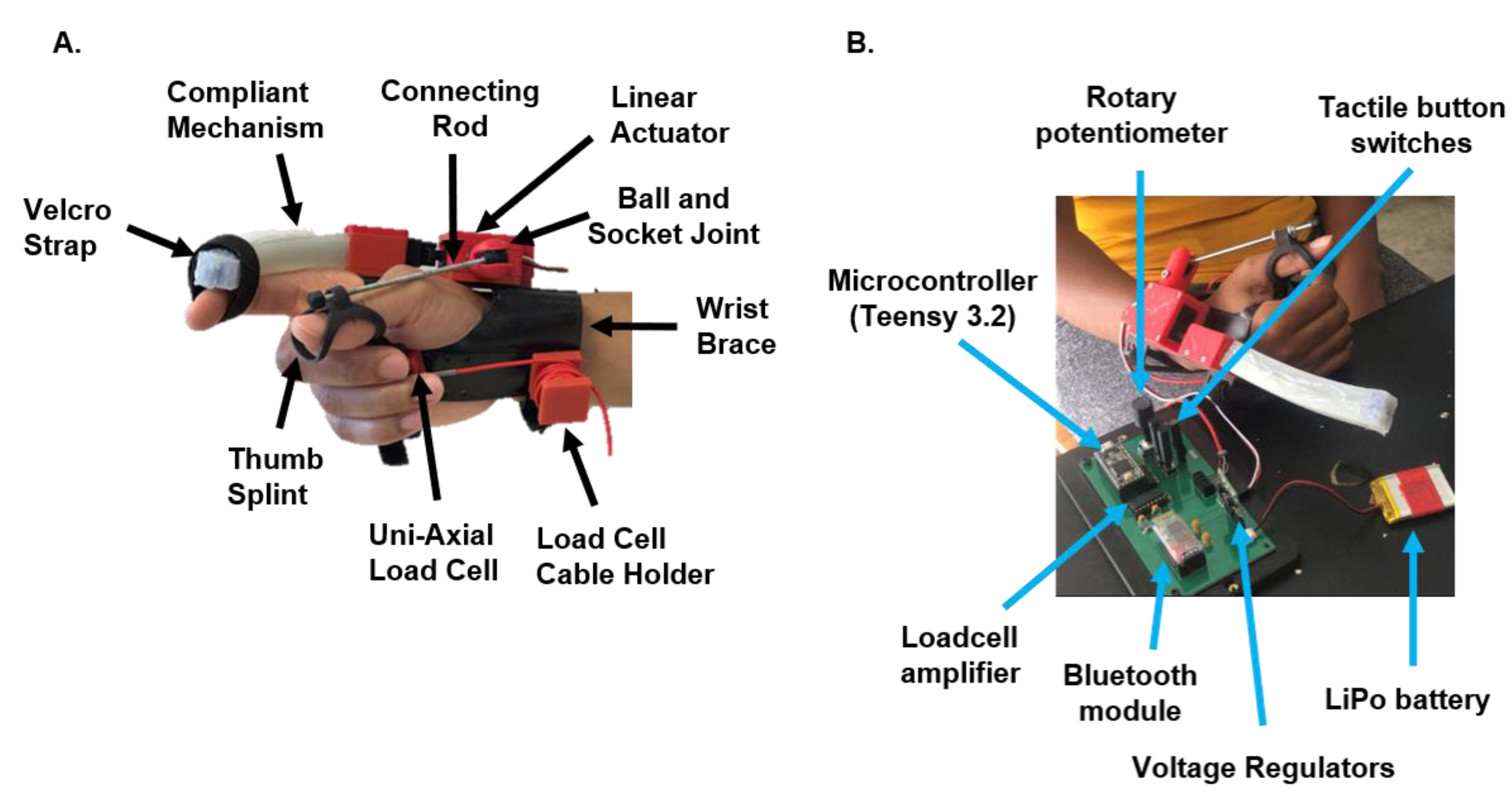
2.1. System Overview

The IGripX hand exoskeleton (Figure 1) is composed of a compliant mechanism connected to a linear actuator (PQ12-R, Actuonix, Saanichton, BC, Canada) (Table 1) for moving the index finger, an adjustable thumb splint, and a palm-based force sensor for controlling the index-finger-compliant mechanism. The mechanism is placed on the lateral aspect of the index finger and facilitates a pinch grip. Furthermore, compliant mechanism is attached via velcro straps that are fixed to the compliant mechanism using Sil-poxy, a silicone adhesive known for creating strong bonds between silicone rubber parts and fabric. We chose to put the compliant mechanism on the lateral aspect of the index finger to improve donning and doffing of the device. Exoskeletons that can be donned primarily from the dorsal side or lateral side can potentially be easier to put on in comparison to glove-based designs which typically are difficult to put on without assistance. The thumb is held in opposition using a ball-and-socket joint that is attached to the side of the exoskeleton. Users can rotate their thumb to the desired position and then lock it in place once they are in a comfortable position. A thumb splint is also connected to the ball-and-socket joint.
We chose to focus on facilitating a pinch grip to reduce the mechanical complexity of the system. Furthermore, several works have shown that there is a small subset of hand grasp postures that are utilized to accomplish various tasks of daily living. Of these postures, an index finger pinch grip, lateral key pinch grip, and a power grasp are among the highest used grasp types [45]. The thumb also plays a fundamental role in grasps that require opposition, thus requiring its support. However, we chose to have the thumb passive as opposed to active to again minimize the mechanical complexity of the system.
The exoskeleton is controlled using an isometric grip force control strategy (IFC) [24], which measures grip force from the remaining digits to control actuation of the index finger. Force is measured using a uni-axial load cell (LSB 200, Futek, Irvine, CA, USA) capable of measuring tensile and compressive forces in one direction (specifically the z axis). The control strategy requires individuals to squeeze on the load cell with digits 3–5, applying a force that is aligned with the primary axis (axis in which the load cell is designed to be loaded) of the load cell. The sensor then measures this exerted grip force and uses it to subsequently control the position of the actuator. A custom-built printed circuit board (PCB) houses the microcontroller (Teensy 3.2, PJRC, Sherwood, OR, USA), which is used to implement the control strategy and acquire data from a force sensor. Additionally, the PCB contains a loadcell amplifier (INA 125P, Texas Instruments, Dallas, TX, USA) and two boost voltage regulators (Pololu, Las Vegas, NV, USA). The entire system is powered using a 3.7 V, 800 mAh, Lithium-ion polymer battery (SparkFun, Niwot, CO, USA) (Figure 1).

2.2. Fabrication and Working Principle of Compliant Mechanism

The compliant mechanism developed in this study was composed of two different layers. The bottom layer was composed of a low durometer silicone rubber (Eco-flex 00-30, Smooth-On Inc., Macungie, PA, USA) while the top layer consisted of a higher durometer silicone rubber (Dragonskin 30, Smooth-On Inc., USA). Prior to pouring the silicone mixture into a 3D-printed mold, a piece of spring steel wrapped in tape and coated with petrolatum was inserted through a channel in the mold. After the spring steel was placed in position, the silicone mixture was poured into the base of the mold, sealed, and then allowed to sit for approximately 45 min. During that time, we created the mixture for the top silicone layer composed of Dragon skin 30. Once the Eco-Flex 00-30 layer reached gel time (initial semisolid phase that develops during the formation of a resin from a liquid), we removed the top of the mold and poured the Dragon skin 30 silicone mixture on top of the Eco-Flex 00-30 mixture. The top of the mold was then placed back on to the base of the mold, and the complete silicone mixture was given time to cure. In total, this process took approximately 14 h. Once the curing process finished, the structure was removed from the mold. The spring steel was then removed from the silicone and cleaned to remove the petrolatum and tape. The spring steel was then inserted through the channel created in the complete silicone structure until it passed completely through the structure. A 3D-printed rectangular disc was attached to one end of the spring steel while on the other end of the steel another 3D-printed plate and clevis piece were attached. Finally, the clevis piece was attached to the linear actuator (Figure 2).
The working principle behind the compliant mechanism is based on concepts from beam theory. When an axial load surpasses the Euler critical load of a cantilever beam, it buckles in one of two directions, determined by the beam’s physical properties. In homogeneous, isotropic beams, there is no preference, but in anisotropic beams, the direction of buckling favors the region with lower stiffness. The compliant mechanism designed here effectively acts as a cantilever beam attached to the finger. During operation, the linear actuator pulls the spring steel member, causing the 3D-printed end cap to compress both silicone rubber layers. This compression causes the entire structure to buckle, with preference given towards the region with the lower stiffness. In our design, the lower durometer silicone rubber is the bottom layer; thus, when actuation occurs, the actuator bends in a manner similar to finger flexion (Figure 3).

2.3. Residual Isometric Grip Force Control Strategy

The use of sEMG and the use of manual triggers have indeed been the predominate control strategies utilized in the hand exoskeleton space. However, one alternative approach to these two strategies is the use of isometric grip force as a control input. Typically, in this control paradigm, force sensors are attached to the tips of the actuated fingers and the measured force is used to control grasping assistance, either proportionally or by a threshold [31]. While this strategy is simple to implement, there are some limitations to this approach. First, in its current implementation it is primarily designed to assist with flexion. This is certainly useful for individuals who experience grasping weakness; however, in persons with stroke, extension capabilities tend to be more impaired than flexion [46]. As such, this type of control strategy may not be suitable for users who experience deficits in both flexions and would require a moderate level of hand function.
Recently, there has been a small set of studies that have shown that persons with stroke possess precise control of isometric grip force in the impaired hand at low ranges of maximum voluntary contraction. For example, Lindberg et al. [47] found that when examining grip force tracking, there were no significant differences in grip force tracking error or variability between persons with a stroke and control subjects at matched absolute force levels (corresponding to about 2.5%, 5%, and 7.5% of their maximum voluntary contraction—MVC), even though the average maximal grip force in the paretic hand was reduced on average by about 75% [48]. These investigators concluded that “stroke patients can generate and hold low grip forces just as well as control subjects can”. Similarly, in our previous work, 17 individuals in the chronic phase of stroke played a grip force tracking game. Participants squeezed a load cell using a power grip to move a cursor into a target at different force levels, defined to be 3 to 30% of their MVC. Even participants who could be classified as more severely impaired could regularly acquire the target, with only a 29% increase in force acquisition time when comparing the paretic and non-paretic hand force acquisition times (2.6 ±0.77 s and 2.02 ± 0.56 s, respectively). These results further suggest that the ability to regulate submaximal isometric grip force—as measured with a standard grip force target acquisition paradigm—is well preserved after stroke.
These observations led us to design an alternative isometric grip force control strategy that is not dependent upon the interaction of the affected hand and a physical object. In the proposed strategy, force is measured from digits 3–5 using a load cell. This force is sent to a position generator, which consists of a first-order low-pass Butterworth filter (cut-off frequency of 100 Hz) and a linear interpolator. The output of the position generator is then scaled by a gain and sent to the linear actuator (Figure 4). Thus, the control law for the linear actuator is as follows:
θ = F P a l m F P a l m _ m i n × θ m a x θ m i n F P a l m _ m a x F P a l m _ m i n + θ m i n
θ R e f = K a m p × θ
Equation (1) represents the linear interpolator, which adjusts the filtered force signal to fit within the range suitable for the linear actuator (0 to 180°). The linear actuator in our design, functioning similarly to a standard servo motor, operates with an angular orientation range of 0 to 180°, where a fully extended shaft corresponds to 180° and a fully retracted shaft corresponds to 0°. Equation (2) depicts the position command sent to the motor, which is the measured finger force converted to an angular position and then scaled by a gain. The amplification gain is applied to decrease the force required from the user to control the actuator.

2.4. Compliant Mechanism Characterization and Preliminary Evaluation of IGripX Hand Exoskeleton Force Control

We characterized the impedance and the output force of the compliant mechanism using two different approaches. In the first approach, the compliant mechanism was strapped to the index finger of the user, and we measured the resultant pinch grip force exerted by the compliant mechanism on the index finger with a pinch gauge. In the second approach, we examined the motion profile of the compliant mechanism under both unloaded and loaded conditions.
Due to the impact of the COVID-19 pandemic, our ability to evaluate the control strategy in individuals with stroke was hindered by restricted access to patients. However, to assess the intuitiveness and utility of the exoskeleton for individuals with finger weakness, we conducted a physical simulation mimicking the condition of a post-stroke person with a completely flaccid index finger and no preserved tactile or proprioceptive sensation.
To do this, we used unimpaired participants as volunteers, but did not attach their index finger to the compliant mechanism. This was done so that any unconscious effort at moving the index finger would not influence the grip. In this scenario, the compliant mechanism instead functioned as a replacement for the user’s index finger like a partial prosthesis. Furthermore, in this “prosthesis mode”, users engaged in a grip–lift–move task under three different conditions: hands only (using their own index finger and thumb), Exo—No Force Modulation (using thumb and compliant mechanism but without the IFC strategy), and Exo—Force Modulation (using thumb and compliant mechanism with the IFC strategy). The goal of this was to evaluate the ability of individuals to improve their performance on the given task when using the IFC strategy.
Additionally, we also wanted to understand user preferences regarding two different parameters that influence the control strategy: operating mode and force sensitivity. Regarding the operating mode, as previously mentioned, the IGripX incorporates the IFC strategy, which maps force exerted by the user’s fingers to movement of the actuator. In this control paradigm the user has control over one degree of freedom, being either flexion or extension of the actuator. This is a similar situation as to what is observed in the control of prosthetic hooks. In the prosthetic literature, there are two strategies one can use to control a prosthetic hook: voluntary opening (VO) or voluntary closing (VC) [49]. A VC strategy allows the user to control closing while a spring maintains the open position of the hook. In contrast to this, a VO strategy enables the user to control opening while a spring is responsible for keeping the hook closed. Each strategy has its own inherent advantages and disadvantages, with users’ preferences towards a given strategy typically dependent upon the task at hand. In the context of the finger exoskeleton, in VC mode of the finger exoskeleton, the initial position is with the finger fully extended, allowing the user to control flexion assistance by squeezing the load cell. When no force is applied to the load cell, the actuator returns to its initial fully extended position. Conversely, in VO mode, the initial position is with the finger fully flexed, enabling the user to control extension assistance by squeezing the load cell. When no force is applied, the actuator returns to its initial fully flexed position. In terms of force sensitivity, the IGripX enables users to control how much force they need to apply by modifying the gain that controls the mapping between force sensed by the palm-based loadcell and position of the actuator. Therefore, when a low gain is applied, users will need to exert more force from digits 3–5 to move the actuator to a specific position. Conversely, with a higher gain applied, users will require less force from digits 3–5 to control the actuator’s position. To evaluate preferences regarding operating mode (i.e., voluntary opening or voluntary closing) and force sensitivity (i.e., low gain or high gain), we had users perform two separate tasks: a lift–grip–hold task, and a water pouring test which required users to pour water from one cup to another.

2.4.1. Measurement of Compliant Mechanism Impedance and Output Force

To measure the impedance of the compliant mechanism, we manually applied a perturbation to displace it from an initial starting position using an instrumented object. The object, similar in shape and dimension to the cup used in the grip–lift–hold task (height: 117 mm, diameter: 55 mm), was instrumented with a uni-axial load cell (LSB 200, Futek, US) placed on the exterior surface of the object. The instrumented object was initially positioned on a table, with the force sensor in contact with the compliant mechanism. This was done so that we could measure the contact force between the mechanism and the object. Force data were recorded for 30 s in this initial position, and the average force measured during this period was calculated. Afterwards, we varied the effective diameter of the object by sliding it towards the mechanism, further displacing it. We moved the object in 2 mm increments, effectively varying the object’s diameter between 55 mm and 65 mm. This impedance measurement was performed a total of five times, at each of the different effective diameters and then the average of the force recorded at each diameter was taken. The measured force was then plotted against the diameter of the cup, and a regression line was fit to these data. The slope of the regression line here represented the impedance of the soft actuator. The impedance was also calculated for five different compliant mechanism positions: 0% (neutral position), 25% flexed, 50% flexed, 75% flexed, 90% flexed. Positions of the actuator were recorded as well.
To assess the output force of the compliant mechanism, we measured the pinch grip force created by the device. During this test, a pinch gauge was placed between the volar surface of the thumb and index finger while the user wore the finger exoskeleton. The participants were asked to relax their hands while the exoskeleton gradually exerted force on the finger. A total of three different measures were taken, with the average representing the peak pinch grip force. Additionally, we also analyzed the motion profile of the compliant mechanism under both unloaded and loaded conditions. During the unloaded condition, we recorded the motion profile of the compliant mechanism as the position of the actuator was cycled between 0 ° and 180 ° in increments of 1 ° . During the loaded condition, a weight of 200 g was attached to the end of the compliant mechanism via a 3D-printed cap, and the position of the actuator was again cycled between 0 ° and 180 ° in increments of 1 ° . The motion profile of the mechanism during both conditions was recorded using a camera, and differences between the unloaded and loaded motion profile of the mechanism were analyzed qualitatively. This served as an alternative way to approximate the output force of the compliant mechanism.

2.4.2. Participants

To pilot test the intuitiveness of the IGripX control strategy, 10 unimpaired participants (4 males, 6 females, age: 39.1 13.8 SD) were recruited for participation in the study. Additionally, to evaluate user preference regarding the control strategy, we recruited 4 unimpaired participants (3 males, 1 female, age: 28.3 ± 4.8) from the University of California Irvine. This study was approved by the University of California Institutional Review Board (IRB), and all study participants gave their consent prior to participating in the study.

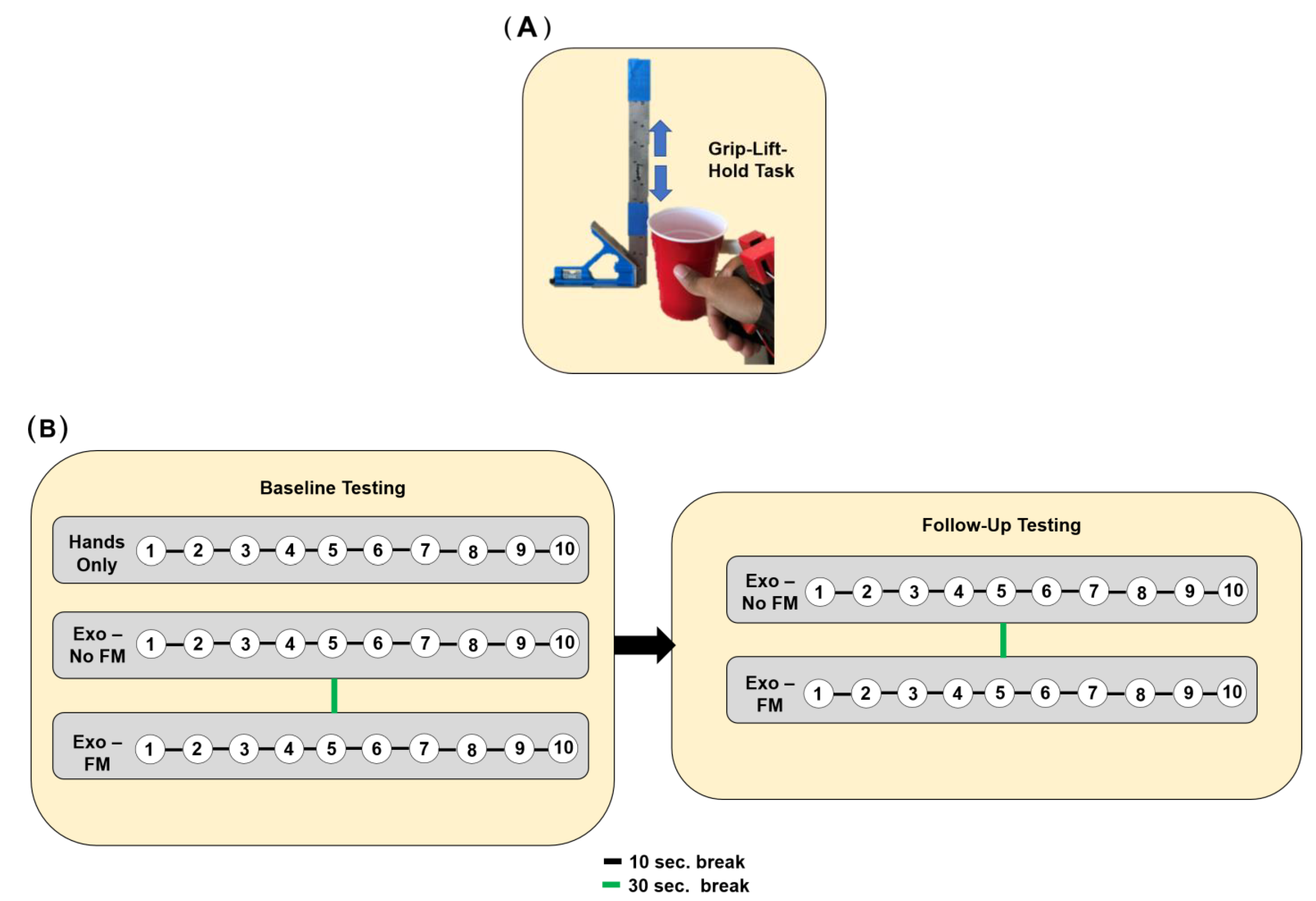
2.4.3. Experimental Protocol—Grip–Lift–Hold Task

Participants were asked to grasp a standard-sized (height: 117 mm, diameter, 82 mm) cup using a pinch grip in three different conditions. During each condition, participants were asked to lift the cup up and down in an oscillating motion between two end points that were marked on a ruler that stood vertically. Participants were asked to perform this oscillating motion for 30 s with the goal of trying to perform as many vertical up–down motions within the allotted time. At the end of each condition, participants were told the number of movements that they were able to achieve in the 30 s time frame, and their frequency of movement was recorded. Here, the frequency of movement represents the total number of movements achieved divided by 30 s. In total, participants performed these 30 s sets 10 times with the goal of trying to increase the number of repetitions they achieved in the subsequent trials. Participants were also given a 10 s break between each trial, and a 30 s break when switching between conditions.
In the first condition, participants used their own index finger and thumb to perform the pinch grip (Hands-Only condition). In the second condition, participants were asked to perform the pinch grip using their thumb and the compliant mechanism; however, the mechanism was powered off, meaning that squeezing on the load cell would not cause the mechanism to flex any further than its starting position (Exo—No FM condition). In this condition, the mechanism was also positioned such that it was 90% flexed. In the third condition, subjects again used the compliant mechanism and their thumb to pick up the cup; however, the mechanism was powered on (Exo—FM condition). In this condition, when participants squeezed on the palm-based load cell, this would cause the actuator to flex from 90% to 100%, thus allowing participants to modulate their grip force in this condition.
After the initial experiment, participants were retested three days later, and performed the same grip–lift–move task. In these follow-up tests, participants only performed the task with the exoskeleton-powered-off and exoskeleton-powered-on conditions. For both the baseline test and the follow-up test, the order in which participants experienced the conditions was randomized (Figure 5).

2.4.4. Experimental Protocol—User Preference

Two different tasks were performed to understand user preference regarding force sensitivity and operating mode: a lift–grip–hold task and a water pouring task. There were two different force sensitivity levels that users could choose from: a low gain, which required the user to exert more force on the load cell to control the position of the actuator, and a high gain, which required the user to exert significantly less force on the load cell to control position of the actuator. Regarding the operating mode, users could utilize either a VC strategy to perform the task or a VO strategy. During the lift–grip–hold task, users performed 5 sets including 5 lifts of a cup filled with water (weight—500 g) for 10 s each. During the water pouring task, two cups were placed in front of the participants: one empty cup, and another cup filled with water. During the task, participants were timed and required to pour water from one cup to the other. Participants performed this task a total of three times. In total, there were four different conditions in which participants could perform the tasks: voluntary opening with low gain (VOLG), voluntary opening with high gain (VOHG), voluntary closing with low gain (VCLG), voluntary closing with high gain (VCHG). The order in which each condition was experienced was randomized. At the conclusion of the experiment, participants were asked to comment on each strategy utilized.

3. Results

3.1. The Compliant Mechanism Exhibited Low Impedance and Could Exert a Moderate Amount of Force

The impedance of our actuator varied substantially in response to the flexed position of the actuator (Figure 6). The maximum impedance value we calculated for the actuator was 34.77 N/m and was measured when the actuator was 90% flexed. This impedance value was comparatively low when compared to normative impedance values of the human index finger [50].
The motion profile of the mechanism was distorted when a load was applied (Figure 7), which is likely a result of the low impedance of the mechanism. However, when the mechanism was attached to the finger, the mechanism could be properly guided by the user’s finger structure, possibly eliminating this distortion. During the pinch force assessment, the hand exoskeleton exerted approximately 2.3 ± 0.57 N, as measured by the pinch gauge.

3.2. Individuals Are Able to Rapidly Improve Task Performance When Using Isometric Force Control Strategy

The frequency at which people were able to move the cup was significantly greater when individuals were able to modulate their grip force with the exoskeleton (Exo—Force Modulation) in comparison to when individuals could not modulate their grip force (Exo—No Force Modulation) (p < 0.01, Two-tailed paired t-test, α = 0.05) (Figure 8). Additionally, when individuals were able to modulate their grip force, they increased the frequency at which they were able to move the object, starting on average with an initial frequency of 1.2 Hz and finishing with an average frequency of 1.75 Hz by the 10th trial (an increase of 46%). This trend, however, was not statistically significant. Similar trends were also seen when looking at the follow-up data, with subjects increasing their frequency from 1.2 Hz in the first trial to 1.6 Hz. by the 10th trial when they were able to modulate their grip force. However, when comparing the achieved frequencies from the follow-up visit to the frequencies achieved at baseline, the follow-up frequencies were lower. This suggested that retention of the control strategy is low, although it may also be a product of the relatively small sample size (only six subjects were available for follow-up testing). Participants also became more efficient at using the strategy, gradually decreasing the amount of force used over time (p = 0.03, Linear Regression Analysis, α = 0.05) (Figure 9). But there was not a trend in the standard deviation of force exerted by the participants during the task, suggesting that participants did not learn how to perform “quick” grip force modulation in response to inertia and slips.

3.3. Individuals Prefer a Voluntary Opening Strategy as Opposed to Voluntary Close While Preferences on Force Sensitivity Are Task Dependent

Participants were able to achieve the fastest water transfer time utilizing the VC strategy with the higher gain (9.1 ± 2.3 s) in comparison to the other strategies (Table 2). However, contrary to this, in interviews with each of the participants, users indicated that they preferred the VO strategy despite the slower times (VO low gain: 11.5 ± 2.6 s, VO high gain: 10.4 ± 3.1 s). Only one participant stated that they preferred to use the VC strategy during the pouring task. The users that preferred to use the VO strategy also preferred to use the higher gain setting while the participant that preferred the VC strategy preferred the lower gain setting.
Regarding the grip–lift–hold task, all of the participants preferred the VO strategy, with two of the users preferring to use the VO strategy with a lower gain, and the other two participants preferring to use the VO strategy with a higher gain. The most common statement made by the participants regarding both tasks was that the VO strategy was less fatiguing, allowing users to concentrate on maintaining stability, while the VC felt more fatiguing both cognitively and physically, as users had to actively push on the load cell to maintain the grip. One user did note that despite the fact that the VC strategy was more demanding, the strategy felt “more natural” in comparison to the other strategy. Interestingly, all subjects stated that it would be nice to switch between the two different operating modes. Given the small sample size, no inferential statistics were performed, but we further discuss these qualitative results in the Discussion section.

4. Discussion

We designed a hand exoskeleton that incorporated a novel compliant mechanism and a novel force control strategy. We evaluated the force control strategy in a pilot study and also performed characterization of the compliant mechanism. Below, we discuss in greater detail the ramifications of these results.

4.1. A Novel Compliant Mechanism with Low Impedance and Moderate Force Production Capabilities

In this work, we developed a novel compliant mechanism. Compliant mechanisms have several advantages compared to other transmission approaches used in hand exoskeletons, such as no backlash, no lubrication required, quiet operation, and small form factor. Recently, several hand exoskeletons have utilized compliant mechanisms that are based on spring steel members and operate using principles from bending beam theory. These designs have been able to achieve output forces sufficient enough to enable individuals with low tone and low spasticity to perform grasping movements [16,17,18]. One of the primary differences between our device and existing hand exoskeletons that incorporate compliant mechanisms is the reduced number of parts. For example, in the work of Butzer et al., the developed hand exoskeleton consists of more than 100 individual parts. The device here uses significantly fewer components, and although the fabrication process for the compliant mechanisms is a multi-step process, it could be easily simplified using 3D printing. The compliant mechanism developed in this work also was shown to have very low impedance. To better understand this impedance value, we looked at work published that examined the impedance of the human index finger. In the work of Hajian et al. [50], the average impedance of the index finger was characterized for six adults during extension and abduction movements for forces ranging between 2–20 N and 2–8 N, respectively. It was observed that for extension movements, fingertip impedance values varied substantially, with the following averages of 137.32 ± 75.86 N/m (2 N), 479 ± 141.15 N/m (8 N), 845.2 ± 198.17 N/m (20 N) for extension. It should also be noted that of the five subjects, one subject had an average index finger impedance of 41.6 N/m. This impedance value is similar to that calculated for one subject but is comparatively low when compared to the average of all five subjects in the study. Given the materials that were used to fabricate the mechanism, it is not a surprise that the impedance is considerably low. Also, this low impedance value may potentially be a favorable attribute of the mechanism in comparison to other transmission approaches (such as linkage-based systems), as the low impedance of the actuator would allow the user to initiate and follow desired movement trajectories with little interference from the mechanism. Finally, although the force generated from the mechanisms is comparatively low when considering other hand exoskeletons, it is able to assist with both flexion and extension movements in a simplified form factor. For tendon-driven exoskeletons which have become one of the primary actuation mechanisms utilized in hand exoskeletons, additional components such as pulleys are required to enable the exoskeleton to apply and transmit forces bimanually, which can increase the bulk of the device.

4.2. Feasibility of Isometric Force Control to Enable Robust Control of Finger Exoskeleton

We have implemented the IFC strategy in a rigid table top hand exoskeleton [24] and, in the current study with the IGripX, a soft finger exoskeleton. Both studies concluded that the control strategy was intuitive to learn, allowing able-bodied participants to improve their performance on a given task within a relatively short time frame. In this study for example, at the conclusion of the grip-lift-hold task in the Exo—Modulation condition, participants had only used the device with the control strategy for a total of six minutes (this is accounting for breaks given between trials.). For comparison, calibration routines alone for EMG-based control strategies can often take anywhere between 2–5 min. This also does not account for the amount of time dedicated to practicing with the strategy that typically follows afterwards. Thus, measuring the intact force in the hand after a stroke provides a direct method to control a hand or finger exoskeleton that is simple to implement, requiring no training data or extensive calibration routine. Furthermore, directly coupling the input (in this case force) to the grasping movement for control is inherently intuitive.
A similar observation was also made by Ciullo et al. [51]. In that study, the feasibility of controlling a supernumerary limb with isometric grip force was evaluated in ten persons in the chronic phase of stroke. A grasp force handle was placed in the hand of the user while a supernumerary limb was mounted to the forearm of the user. To operate the limb, the user would squeeze on the transducer with all five fingers, and this subsequently controlled flexion and extension of the limb. The strategy was compared to a simple manual trigger (i.e., a push button) and bend sensors, with results of the study showing that the control strategy achieved satisfactory system usability scale scores amongst users. All three of these aforementioned studies highlight the potential of the strategy as an intuitive alternative approach to conventional intent-detection strategies. But what is important to note, however, is that the application of the strategy is important. For example, this strategy enables the user to control one degree of freedom (DOF), namely a pinch grip in our case, due to the use of the remaining fingers for control. This is not a significant limitation as there exist several hand exoskeletons that facilitate only a pinch grip due to its utility. But, with the proposed strategy, it would be rather difficult to control a multi-DOF system (e.g., a hand exoskeleton capable of power grasp, pinch grip, lateral pinch grip, etc.). Thus, for applications that require users to switch between different hand grasps or move the fingers individually, other strategies may be more applicable. In applications where the hand is acting in a supporting role, such as during grasping tasks, this strategy may be more advantageous in comparison to other more complex strategies (e.g., EMG control). Future studies, then, could further elucidate this point, evaluating the ability of persons with stroke to perform various activities in a laboratory-based setting as well as a home-based setting with a hand exoskeleton incorporating the control strategy.

4.3. Optimal Parameters for Improving Usability of Isometric Force Control Strategy

In the present study, individuals noted that at times they felt that it was both physically and cognitively fatiguing to use the voluntary closing strategy, as it necessitated continuous pressure on the load cell to regulate the force of the compliant mechanism. Despite this limitation, users found the VC strategy intuitive, with one user expressing that it “felt more natural and integrated into his hand” compared to the VO strategy. They also noted better grip force control with the VC strategy during both the grip–lift–hold task and the water pouring task. Furthermore, participants indicated that in other tasks where grip force control is critical (e.g., holding a fragile object, holding a glass of water), the VC strategy would be preferred. However, although the VC strategy felt more natural, participants generally preferred the VO strategy (regardless of the gain used) due to its lower physical and cognitive demands. This was particularly evident during the water pouring tasks, in which individuals indicated that only having to concentrate on positioning the glass was far less demanding when compared to the VC strategy, which required users to concentrate on maintaining an appropriate level of grip force while also positioning the glass. Thus, there are perceived benefits to using such an approach during more complex tasks. This observation is not specific to the IGripX exoskeleton, and has also been observed in the prosthetic literature with terminal hooks [49]. Furthermore, it has been shown in the prosthetic space that individuals typically favor the use of voluntary opening strategies for tasks that require simultaneous movement (e.g., placing objects), while voluntary closing strategies are often preferred for tasks that require force control (e.g., manipulating objects). However, the limitation of the VO strategy is the lack of grip force control. Many of the participants noted during the water pouring task that they did not feel confident in the stability of their grasp.
Interestingly, another observation that was shared between participants in our study and participants using terminal hooks was the desire to switch between either strategy. This potentially could offer users the best of both worlds, and in the prosthetic space there have been terminal devices developed that offer these two operating modes. For example, in the work of Sensinger et al. [49], a split hook design was developed that could switch been VC and VO strategies using a toggle switch. In future work with the IGripX exoskeleton, a similar strategy could be explored to give the exoskeleton the capability of switching between VC and VO modes. Another approach could also be to make the switching between modes automatic by relying on information from tactile sensors, for example, to control switching between the two modes. Finally, several key questions also remain regarding the optimization of this control strategy for persons with stroke. For example, what are the appropriate cutoffs for low-pass filtering of grip force and movement noise? How does cognitive demand compare to other control strategies? Do users have a preference towards operating mode (e.g., voluntary open or voluntary close; self-selected gain or fixed gain)? Such questions need to be thoroughly investigated to improve the usability of this strategy.

5. Limitations

The actuator had similar levels of impedance as that of the index finger. However, the output force of the actuator was considerably lower in comparison to other actuation strategies. This could possibly be due to the low impedance of the actuator, as one would imagine that an actuator with higher impedance would be able to exert more force. The low output force could also be a result of the material selection or the low mechanical efficiency due to buckling. Our actuator, thus, may not be sufficient for individuals who have increased muscle tone or are more severely impaired. But for individuals who lack tone and have weak grip strength, this actuation strategy could perhaps still allow for completion of some daily activities of living. The current control strategy was also implemented on abled-bodied individuals. Thus, it is unclear if the strategy will be as intuitive in persons with stroke. The sample size of the study was also low, limiting the generalizability of the results.

6. Conclusions

In the present work we proposed the design of a soft hand exoskeleton that incorporated a control strategy based on measuring the isometric grip force of the fingers. The hand exoskeleton was actuated using a soft multi-layered compliant mechanism that showed similar levels of impedance as the index finger. It was shown that the control strategy is intuitive and easy to learn in preliminary experiments. Thus, this strategy could serve as an alternative approach to more complex strategies, although further testing with the target population will be necessary to evaluate feasibility and refine parameters of the strategy.

Author Contributions

Conceptualization, Q.S. and D.J.R.; methodology, Q.S. and D.J.R.; software, Q.S.; validation, Q.S.; formal analysis, Q.S.; investigation, Q.S.; resources, D.J.R.; data curation, Q.S.; writing—original draft preparation, Q.S.; writing—review and editing, Q.S. and D.J.R.; visualization, Q.S.; supervision, D.J.R.; project administration, D.J.R.; funding acquisition, D.J.R. All authors have read and agreed to the published version of the manuscript.

Funding

This work was supported by the Louis-Stokes Alliance for Minority Participation Bridge to the Doctorate Fellowship, the United States Department of Education Graduate Assistance in Areas of National Need, and the National Institute of Child Health and Human Development (NIH R01HD062744).

Data Availability Statement

The data presented in this study are available upon request from the corresponding author. The data are not publicly available due to privacy restrictions.

Conflicts of Interest

The authors declare no conflicts of interest.

References

  1. Barry, A.J.; Kamper, D.G.; Stoykov, M.E.; Triandafilou, K.; Roth, E. Characteristics of the severely impaired hand in survivors of stroke with chronic impairments. Top. Stroke Rehabil. 2022, 29, 181–191. [Google Scholar] [CrossRef] [PubMed]
  2. Hoffmann, G.; Conrad, M.O.; Qiu, D.; Kamper, D.G. Contributions of voluntary activation deficits to hand weakness after stroke. Top. Stroke Rehabil. 2016, 23, 384–392. [Google Scholar] [CrossRef] [PubMed]
  3. Lee, S.W.; Triandafilou, K.; Lock, B.A.; Kamper, D.G. Impairment in Task-Specific Modulation of Muscle Coordination Correlates with the Severity of Hand Impairment following Stroke. PLoS ONE 2013, 8, e68745. [Google Scholar] [CrossRef]
  4. Triandafilou, K.M.; Kamper, D.G. Investigation of hand muscle atrophy in stroke survivors. Clin. Biomech. 2012, 27, 268–272. [Google Scholar] [CrossRef] [PubMed]
  5. Raghavan, P. The nature of hand motor impairment after stroke and its treatment. Curr. Treat. Options Cardiovasc. Med. 2007, 9, 221–228. [Google Scholar] [CrossRef]
  6. Gassert, R.; Dietz, V. Rehabilitation robots for the treatment of sensorimotor deficits: A neurophysiological perspective. J. NeuroEng. Rehabil. 2018, 15, 46. [Google Scholar] [CrossRef] [PubMed]
  7. Raghavan, P. Upper Limb Motor Impairment after Stroke. Phys. Med. Rehabil. Clin. 2015, 26, 599–610. [Google Scholar] [CrossRef] [PubMed]
  8. Jang, S.H. The role of the corticospinal tract in motor recovery in patients with a stroke: A review. NeuroRehabilitation 2009, 24, 285–290. [Google Scholar] [CrossRef] [PubMed]
  9. Maraka, S.; Jiang, Q.; Jafari-Khouzani, K.; Li, L.; Malik, S.; Hamidian, H.; Zhang, T.; Lu, M.; Soltanian-Zadeh, H.; Chopp, M.; et al. Degree of corticospinal tract damage correlates with motor function after stroke. Ann. Clin. Transl. Neurol. 2014, 1, 891–899. [Google Scholar] [CrossRef]
  10. Lin, D.J.; Cloutier, A.M.; Erler, K.S.; Cassidy, J.M.; Snider, S.B.; Ranford, J.; Parlman, K.; Giatsidis, F.; Burke, J.F.; Schwamm, L.H.; et al. Corticospinal Tract Injury Estimated From Acute Stroke Imaging Predicts Upper Extremity Motor Recovery after Stroke. Stroke 2019, 50, 3569–3577. [Google Scholar] [CrossRef] [PubMed]
  11. Stinear, C.M.; Lang, C.E.; Zeiler, S.; Byblow, W.D. Advances and challenges in stroke rehabilitation. Lancet Neurol. 2020, 19, 348–360. [Google Scholar] [CrossRef] [PubMed]
  12. Reinkensmeyer, D.J.; Dietz, V. (Eds.) Neurorehabilitation Technology; Springer International Publishing: Cham, Switzerland, 2016; ISBN 978-3-319-28601-3. [Google Scholar] [CrossRef]
  13. Allred, R.P.; Kim, S.Y.; Jones, T.A. Use it and/or lose it—Experience effects on brain remodeling across time after stroke. Front. Hum. Neurosci. 2014, 8. [Google Scholar] [CrossRef] [PubMed]
  14. Bakhti, K.; Mottet, D.; Schweighofer, N.; Froger, J.; Laffont, I. Quantification of learned non-use of the upper limb after a stroke. Ann. Phys. Rehabil. Med. 2015, 58, e4. [Google Scholar] [CrossRef]
  15. Molle Da Costa, R.D.; Luvizutto, G.J.; Martins, L.G.; Thomaz De Souza, J.; Regina Da Silva, T.; Alvarez Sartor, L.C.; Winckler, F.C.; Modolo, G.P.; Molle, E.R.D.S.D.; Dos Anjos, S.M.; et al. Clinical factors associated with the development of nonuse learned after stroke: A prospective study. Top. Stroke Rehabil. 2019, 26, 511–517. [Google Scholar] [CrossRef] [PubMed]
  16. Lieber, J.; Dittli, J.; Lambercy, O.; Gassert, R.; Meyer-Heim, A.; van Hedel, H.J.A. Clinical utility of a pediatric hand exoskeleton: Identifying users, practicability, and acceptance, and recommendations for design improvement. J. NeuroEng. Rehabil. 2022, 19, 17. [Google Scholar] [CrossRef] [PubMed]
  17. Bützer, T.; Lambercy, O.; Arata, J.; Gassert, R. Fully Wearable Actuated Soft Exoskeleton for Grasping Assistance in Everyday Activities. Soft Robot. 2021, 8, 128–143. [Google Scholar] [CrossRef] [PubMed]
  18. Li, M.; He, B.; Liang, Z.; Zhao, C.-G.; Chen, J.; Zhuo, Y.; Xu, G.; Xie, J.; Althoefer, K. An Attention-Controlled Hand Exoskeleton for the Rehabilitation of Finger Extension and Flexion Using a Rigid-Soft Combined Mechanism. Front. Neurorobotics 2019, 13, 34. [Google Scholar] [CrossRef] [PubMed]
  19. Polygerinos, P.; Wang, Z.; Galloway, K.C.; Wood, R.J.; Walsh, C.J. Soft robotic glove for combined assistance and at-home rehabilitation. Robot. Auton. Syst. 2015, 73, 135–143. [Google Scholar] [CrossRef]
  20. Kang, B.B.; Choi, H.; Lee, H.; Cho, K.-J. Exo-Glove Poly II: A Polymer-Based Soft Wearable Robot for the Hand with a Tendon-Driven Actuation System. Soft Robot. 2019, 6, 214–227. [Google Scholar] [CrossRef] [PubMed]
  21. Xiloyannis, M.; Cappello, L.; Khanh, D.B.; Yen, S.-C.; Masia, L. Modelling and design of a synergy-based actuator for a tendon-driven soft robotic glove. In Proceedings of the 2016 6th IEEE International Conference on Biomedical Robotics and Biomechatronics (BioRob), Singapore, 26–29 June 2016; pp. 1213–1219. [Google Scholar] [CrossRef]
  22. Gasser, B.W.; Bennett, D.A.; Durrough, C.M.; Goldfarb, M. Design and preliminary assessment of Vanderbilt hand exoskeleton. In Proceedings of the 2017 International Conference on Rehabilitation Robotics (ICORR), London, UK, 17–20 July 2017; pp. 1537–1542. [Google Scholar] [CrossRef]
  23. Rose, C.G.; O’Malley, M.K. Hybrid Rigid-Soft Hand Exoskeleton to Assist Functional Dexterity. IEEE Robot. Autom. Lett. 2019, 4, 73–80. [Google Scholar] [CrossRef]
  24. Sanders, Q.; Okita, S.; Lobo-Prat, J.; Schwerz de Lucena, D.; Smith, B.; Reinkensmeyer, D. Design and Control of a Novel Grip Amplifier to Support Pinch Grip with a Minimal Soft Hand Exoskeleton. In Proceedings of the 2018 7th IEEE International Conference on Biomedical Robotics and Biomechatronics (Biorob), Enschede, The Netherlands, 26–29 August 2018; p. 1094. [Google Scholar] [CrossRef]
  25. Xiloyannis, M.; Cappello, L.; Binh, K.D.; Antuvan, C.W.; Masia, L. Preliminary design and control of a soft exosuit for assisting elbow movements and hand grasping in activities of daily living. J. Rehabil. Assist. Technol. Eng. 2017, 4. Available online: https://journals.sagepub.com/doi/full/10.1177/2055668316680315 (accessed on 29 February 2024). [CrossRef] [PubMed]
  26. Ho, N.S.K.; Tong, K.Y.; Hu, X.L.; Fung, K.L.; Wei, X.J.; Rong, W.; Susanto, E.A. An EMG-driven exoskeleton hand robotic training device on chronic stroke subjects: Task training system for stroke rehabilitation. In Proceedings of the 2011 IEEE International Conference on Rehabilitation Robotics, Zurich, Switzerland, 29 June–1 July 2011; pp. 1–5. [Google Scholar] [CrossRef]
  27. Leonardis, D.; Chisari, C.; Bergamasco, M.; Frisoli, A.; Barsotti, M.; Loconsole, C.; Solazzi, M.; Troncossi, M.; Mazzotti, C.; Castelli, V.P.; et al. An EMG-Controlled Robotic Hand Exoskeleton for Bilateral Rehabilitation. IEEE Trans. Haptics 2015, 8, 140–151. [Google Scholar] [CrossRef]
  28. Sierotowicz, M.; Lotti, N.; Nell, L.; Missiroli, F.; Alicea, R.; Zhang, X.; Xiloyannis, M.; Rupp, R.; Papp, E.; Krzywinski, J.; et al. EMG-Driven Machine Learning Control of a Soft Glove for Grasping Assistance and Rehabilitation. IEEE Robot. Autom. Lett. 2022, 7, 1566–1573. [Google Scholar] [CrossRef]
  29. Ghassemi, M.; Kamper, D.G. A Hand Exoskeleton for Stroke Survivors’ Activities of Daily Life. In Proceedings of the 2021 43rd Annual International Conference of the IEEE Engineering in Medicine & Biology Society (EMBC), Guadalajara, Mexico, 1–5 November 2021; pp. 6734–6737. [Google Scholar] [CrossRef]
  30. Bos, R.A.; Haarman, C.J.W.; Stortelder, T.; Nizamis, K.; Herder, J.L.; Stienen, A.H.A.; Plettenburg, D.H. A structured overview of trends and technologies used in dynamic hand orthoses. J. NeuroEng. Rehabil. 2016, 13, 62. [Google Scholar] [CrossRef] [PubMed]
  31. Gantenbein, J.; Dittli, J.; Meyer, J.T.; Gassert, R.; Lambercy, O. Intention Detection Strategies for Robotic Upper-Limb Orthoses: A Scoping Review Considering Usability, Daily Life Application, and User Evaluation. Front. Neurorobotics 2022, 16, 815693. [Google Scholar] [CrossRef] [PubMed]
  32. Tran, P.; Jeong, S.; Herrin, K.R.; Desai, J.P. Review: Hand Exoskeleton Systems, Clinical Rehabilitation Practices, and Future Prospects. IEEE Trans. Med. Robot. Bionics 2021, 3, 606–622. [Google Scholar] [CrossRef]
  33. Xiloyannis, M.; Alicea, R.; Georgarakis, A.-M.; Haufe, F.L.; Wolf, P.; Masia, L.; Riener, R. Soft Robotic Suits: State of the Art, Core Technologies, and Open Challenges. IEEE Trans. Robot. 2022, 38, 1343–1362. [Google Scholar] [CrossRef]
  34. Singh, R.M.; Chatterji, S. Trends and Challenges in EMG Based Control Scheme of Exoskeleton Robots—A Review. Int. J. Sci. Eng. Res. 2012, 3, 933–940. [Google Scholar]
  35. Zhang, J.; Sheng, J.; O’Neill, C.T.; Walsh, C.J.; Wood, R.J.; Ryu, J.-H.; Desai, J.P.; Yip, M.C. Robotic Artificial Muscles: Current Progress and Future Perspectives. IEEE Trans. Robot. 2019, 35, 761–781. [Google Scholar] [CrossRef]
  36. Heo, P.; Gu, G.M.; Lee, S.; Rhee, K.; Kim, J. Current hand exoskeleton technologies for rehabilitation and assistive engineering. Int. J. Precis. Eng. Manuf. 2012, 13, 807–824. [Google Scholar] [CrossRef]
  37. Yap, H.K.; Lim, J.H.; Nasrallah, F.; Goh, J.C.H.; Yeow, R.C.H. A soft exoskeleton for hand assistive and rehabilitation application using pneumatic actuators with variable stiffness. In Proceedings of the 2015 IEEE International Conference on Robotics and Automation (ICRA), Seattle, WA, USA, 26–30 May 2015; pp. 4967–4972. [Google Scholar] [CrossRef]
  38. Cappello, L.; Meyer, J.T.; Galloway, K.C.; Peisner, J.D.; Granberry, R.; Wagner, D.A.; Engelhardt, S.; Paganoni, S.; Walsh, C.J. Assisting hand function after spinal cord injury with a fabric-based soft robotic glove. J. NeuroEng. Rehabil. 2018, 15, 59. [Google Scholar] [CrossRef]
  39. Cempini, M.; Cortese, M.; Vitiello, N. A Powered Finger–Thumb Wearable Hand Exoskeleton with Self-Aligning Joint Axes. IEEEASME Trans. Mechatron. 2015, 20, 705–716. [Google Scholar] [CrossRef]
  40. Sarac, M.; Solazzi, M.; Sotgiu, E.; Bergamasco, M.; Frisoli, A. Design and kinematic optimization of a novel underactuated robotic hand exoskeleton. Meccanica 2017, 52, 749–761. [Google Scholar] [CrossRef]
  41. Randazzo, L.; Iturrate, I.; Perdikis, S.; Millan, J.d.R. Mano: A Wearable Hand Exoskeleton for Activities of Daily Living and Neurorehabilitation. IEEE Robot. Autom. Lett. 2018, 3, 500–507. [Google Scholar] [CrossRef]
  42. Yang, S.-H.; Koh, C.-L.; Hsu, C.-H.; Chen, P.-C.; Chen, J.-W.; Lan, Y.-H.; Yang, Y.; Lin, Y.-D.; Wu, C.-H.; Liu, H.-K.; et al. An Instrumented Glove-Controlled Portable Hand-Exoskeleton for Bilateral Hand Rehabilitation. Biosensors 2021, 11, 495. [Google Scholar] [CrossRef] [PubMed]
  43. Sun, Y.; Liu, Y.; Pancheri, F.; Lueth, T.C. LARG: A Lightweight Robotic Gripper with 3-D Topology Optimized Adaptive Fingers. IEEEASME Trans. Mechatron. 2022, 27, 2026–2034. [Google Scholar] [CrossRef]
  44. Zhang, N.; Ge, L.; Xu, H.; Zhu, X.; Gu, G. 3D printed, modularized rigid-flexible integrated soft finger actuators for anthropomorphic hands. Sens. Actuators Phys. 2020, 312, 112090. [Google Scholar] [CrossRef]
  45. Feix, T.; Romero, J.; Schmiedmayer, H.-B.; Dollar, A.M.; Kragic, D. The GRASP Taxonomy of Human Grasp Types. IEEE Trans. Hum.-Mach. Syst. 2016, 46, 66–77. [Google Scholar] [CrossRef]
  46. Conrad, M.O.; Kamper, D.G. Isokinetic strength and power deficits in the hand following stroke. Clin. Neurophysiol. 2012, 123, 1200–1206. [Google Scholar] [CrossRef] [PubMed]
  47. Lindberg, P.G.; Roche, N.; Robertson, J.; Roby-Brami, A.; Bussel, B.; Maier, M.A. Affected and unaffected quantitative aspects of grip force control in hemiparetic patients after stroke. Brain Res. 2012, 1452, 96–107. [Google Scholar] [CrossRef] [PubMed]
  48. Smith, B.W.; Rowe, J.B.; Reinkensmeyer, D.J. Real-time slacking as a default mode of grip force control: Implications for force minimization and personal grip force variation. J. Neurophysiol. 2018, 120, 2107–2120. [Google Scholar] [CrossRef] [PubMed]
  49. Sensinger, J.W.; Lipsey, J.; Thomas, A.; Turner, K. Design and evaluation of voluntary opening and voluntary closing prosthetic terminal device. J. Rehabil. Res. Dev. 2015, 52, 63–76. [Google Scholar] [CrossRef] [PubMed]
  50. Hajian, A.Z.; Howe, R.D. Identification of the Mechanical Impedance at the Human Finger Tip. J. Biomech. Eng. 1997, 119, 109–114. [Google Scholar] [CrossRef] [PubMed]
  51. Ciullo, A.S.; Catalano, M.G.; Bicchi, A.; Ajoudani, A. A Supernumerary Soft Robotic Limb for Reducing Hand-Arm Vibration Syndromes Risks. Front. Robot. AI 2021, 8, 650613. [Google Scholar] [CrossRef] [PubMed]
Figure 1. (A) IGripX hand exoskeleton overview. The IGripX hand exoskeleton is composed of a novel soft compliant mechanism for assisting index finger movement and a force sensor placed in the palm of the hand. The exoskeleton is controlled using an IFC strategy which requires the user to press on the force sensor to control movement of the compliant mechanism. The electrical components, including the motor driver, battery, voltage regulators, and microcontroller, are also shown above. (B) IGripX hand exoskeleton experimental condition. To evaluate the intuitiveness and ability of the hand exoskeleton to assist individuals with finger weakness, we had able-bodied participants perform a set of tasks while wearing the exoskeleton in “prosthesis mode”. In this mode, the compliant mechanism represented a flaccid index finger without tactile or proprioceptive feedback. Movement of the mechanism was controlled using the IFC strategy.
Machines 12 00230 g001
Figure 2. Fabrication process for compliant mechanism. (I) The 3D-printed mold features an inlet allowing the spring steel to pass through completely before fabricating the soft silicone body. (II) The Ecoflex 00-30 silicone mixture is prepared and poured into the mold to form the bottom layer of the mechanism. It is allowed to cure until reaching the gel phase. (III) Once the Ecoflex 00-30 silicone reaches the gel phase, the Dragonskin 30 silicone mixture is prepared and poured on top of it. (IV) The top part of the 3D-printed mold is then placed onto the bottom part to fully encase the combined silicone mixture. It is left to cure for 14 h. (V) After curing, the mechanism is removed from the mold. A 3D-printed rectangular disc is attached to one end of the spring steel, while a regular plate is attached to the silicone body at the other end. A channel in the rectangular plate allows the steel to slide through. (VI) The compliant mechanism is now complete.
Machines 12 00230 g002
Figure 3. Working principle of compliant mechanism. When the linear actuator applies an axial force to the spring steel member, the spring steel member is pulled, pushing into the silicone rubber body. This causes the 3D-printed discs mounted at the end of the spring steel member to push the top and bottom silicone layer into the 3D-printed plate, which is fixed. As a result of this action, the silicone body buckles towards the area with lower stiffness or, in this case, the bottom layer of the silicone body. This generates a bending profile that resembles that of finger flexion.
Machines 12 00230 g003
Figure 4. Residual force control strategy. In this control paradigm, the thumb is held in opposition while the index finger is assisted by the exoskeleton [24]. Furthermore, the force measured from digits 3–5 are used to control movement of the exoskeleton.
Machines 12 00230 g004
Figure 5. Experimental protocol for griplifthold experiment. (A) GripLiftHold Task. Participants were instructed to grasp a standard-sized cup using a pinch grip in three different conditions: hands only, exoskeleton no force modulation, exoskeleton with force modulation. They were then asked to perform an oscillating motion (represented by the blue arrows in the above figure) between two marked endpoints on a vertically positioned rule, as shown above, with the goal of completing as many vertical up-down motions as possible within 30 s. Frequency of movement was calculated as the total number of movements achieved divided by 30 s. (B) Experimental Protocol for GripLiftHold Task. Participants completed 10 sets of 30 s trials, with 10 s breaks between each trial and 30 s breaks between condition switches. After the initial experiment, participants were retested three days later, performing the task with the exoskeleton both powered off and powered on. It should be noted that the order of the conditions was randomized for both the baseline and follow-up tests.
Machines 12 00230 g005
Figure 6. Characterization of compliant mechanism impedance. The impedance of the compliant mechanism was characterized for multiple positions of the actuator. On the y-axis the force measured by a load cell is displayed, while on the x-axis the effective diameter of the cup used in the impedance calculation is shown. The same methodology used to calculate the impedance when the actuator was 90% flexed was also used to calculate the impedance for these additional configurations. Here, 0% means that the actuator is not flexed.
Machines 12 00230 g006
Figure 7. Compliant mechanism motion profile. In the figure above is a time series of pictures of representative behavior of the output force measurement during two different conditions: unloaded (top) and loaded with a 200 g weight (bottom).
Machines 12 00230 g007
Figure 8. Learning curves generated from use of the IGripX. Initial testing of the exoskeleton with unimpaired participants. Individuals wore the exoskeleton in a “prosthetic mode”. In this mode, the mechanism acted as their index finger, and they performed grasping with the mechanism and their own thumb. The No Exo—Hands Only condition represents when individuals performed the study using their own index finger and thumb. The Exo—No FM condition is representative of when subjects wore the exoskeleton, but the actuator was powered off and subjects could not control their grip force, while the Exo—FM condition is the opposite of this (i.e., subjects could modulate their grip force). Here, * level denotes a statistically significant result with a p value less than the alpha level of 0.05.
Machines 12 00230 g008
Figure 9. Average measured force and standard deviation of measured force during use of IGripX. (A) Force displayed is representative of the average force across all subjects. A linear regression was fit to the data, and both the R2 and p value of the regression line are shown. Standard deviation of the force was shown in a separate plot. (B) The standard deviation is representative of the average standard deviation across all subjects that participated in the study. Here, statistical significance is signified by a p value lower than the alpha level of 0.05.
Machines 12 00230 g009
Table 1. Linear Actuator Specifications.
Max Speed (no load) 10 mm/s
Max Force (lifted)50 N
Stroke Length20 mm
Input Voltage6 V
Mass19 g
Table 2. Time Elapsed during Water Transferring with Different Force Sensitivity and Operating Configurations.
Operating Mode Force SensitivityTime (s)
Voluntary OpenLow Gain11.5 ± 2.6
High Gain10.4 ± 3.1
Voluntary CloseLow Gain10.6 ± 3.0
High Gain9.1 ± 2.3
Disclaimer/Publisher’s Note: The statements, opinions and data contained in all publications are solely those of the individual author(s) and contributor(s) and not of MDPI and/or the editor(s). MDPI and/or the editor(s) disclaim responsibility for any injury to people or property resulting from any ideas, methods, instructions or products referred to in the content.

