1. Introduction
In recent times, there has been a noticeable increase in demand for human–robot collaborations across various sectors. Among the areas where cobots are increasingly used are medical fields such as surgical procedures and functional rehabilitation. Nevertheless, it is essential to recognize that they lack some function to better succeed in surgical operations, like haptic function [
1,
2,
3,
4,
5]. In fact, in the context of robotic surgery, for instance, haptic capabilities serve as an argumentative attribute, enriching the surgeon’s experience with enhanced immersion, particularly in the context of minimally invasive surgery (MIS) [
6,
7].
Extensive research has been carried out in the field of haptic devices, with noteworthy contributions such as Van den Bedem’s proposition in [
8], where a spherical serial master haptic device featuring four degrees of freedom was introduced. The serial architecture design in this context offers a straightforward kinematic structure. However, it carries significant drawbacks, including the necessity to position all actuators along the joint axes. This placement increases the requisite torques and adds weight to the end effector, consequently imposing a heavier burden on the surgeon.
In contrast, various other authors, as described in [
9], have advocated for a spherical parallel manipulator (SPM) characterized with a remote Center of Rotation (CoR) as a haptic device for Minimally Invasive Surgery (MIS). Unlike the serial master haptic device, the SPM situates its actuators at the base, mitigating the inertia-related challenges associated with the system. However, this haptic device, structured with a parallel architecture, grapples with singularities within its workspace. These singularities lead to a reduction in the available degrees of freedom (DoFs) and the amplification of errors in the kinematic transformation.
Hybrid devices, as detailed in reference [
10,
11,
12,
13], have started to make significant inroads across various domains. Saafi et al. [
14] have introduced a novel hybrid haptic device which combines elements of a parallel chain and a serial chain. Within this framework, the parallel chain takes charge of tilt motions, while the serial chain manages both self-rotation and translation.
It is worth noting that this architecture does come with a limitation. The actuator responsible for self-rotation necessitates support from the serial chain, leading to an increase in the weight of the translational component. Consequently, this results in a higher demand for linear actuation torque. In order to overcome this problematic, Meskini et al. [
15] proposed a new haptic hybrid master device intended to be used in laparoscopic surgery. The suggested design is founded upon the association of a parallel chain featuring a 3-RRR parallel planar manipulator, and a serial chain linked through a universal joint as shown in
Figure 1. In order to overcome the difficulty of solving the forward kinematic model (FKM) of such an architecture, Meskini et al. [
16] proposed to use an extra sensor, IMU, placed on the serial chain of the manipulator. Such a method reduces the computing time of the FKM and makes it possible for the nHH to be used in a real-time application where time is crucial.
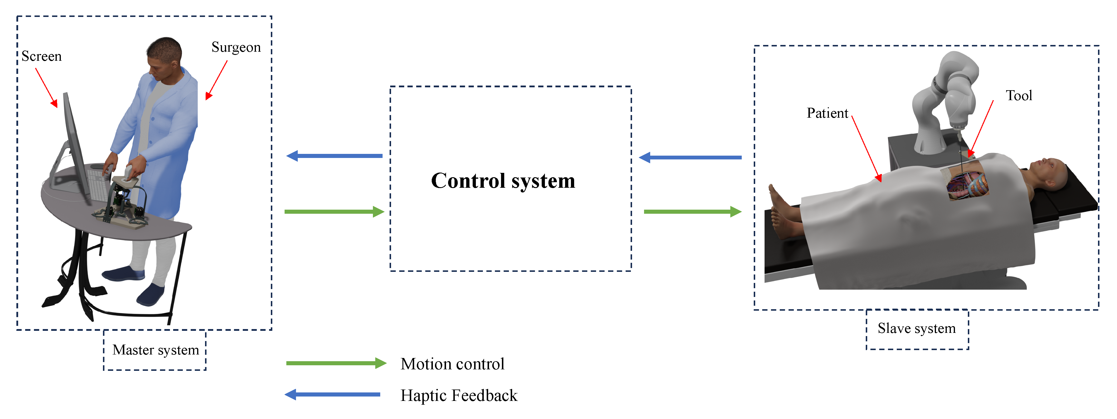
This master device takes part of a master–slave platform which will be presented in this paper. The primary goal of tele-operation systems in the medical field is not to replace autonomous systems but rather to enhance surgical procedures by providing surgeons with increased safety and precision. The tele-operation system comprises a surgical robot referred as the “slave”, a joystick device known as the “master”, and a control system to facilitate the interaction and control between the two as shown in
Figure 2.
The contribution of our work presented in this paper extends beyond the theoretical work presented in previous papers to the practical domain, where we present the experimental validation of the master–slave platform and the analytic validation of the haptic feedback. In fact, this work is mainly focused on the validation of the master device in a real-time application, while using an extra sensor in order to cope with the complexity of the FKM resolution and to make it possible for such application. On the other hand, the haptic force feedback is validated through simulations.
This paper is organized as follows:
Section 2 deals with the presentation of the new hybrid haptic device architecture and the kinematic model of the device.
Section 3 presents the architecture of the master–slave control system and experimental tests.
Section 4 details the analytic validation of the haptic force feedback. Finally,
Section 5 summarizes the paper.
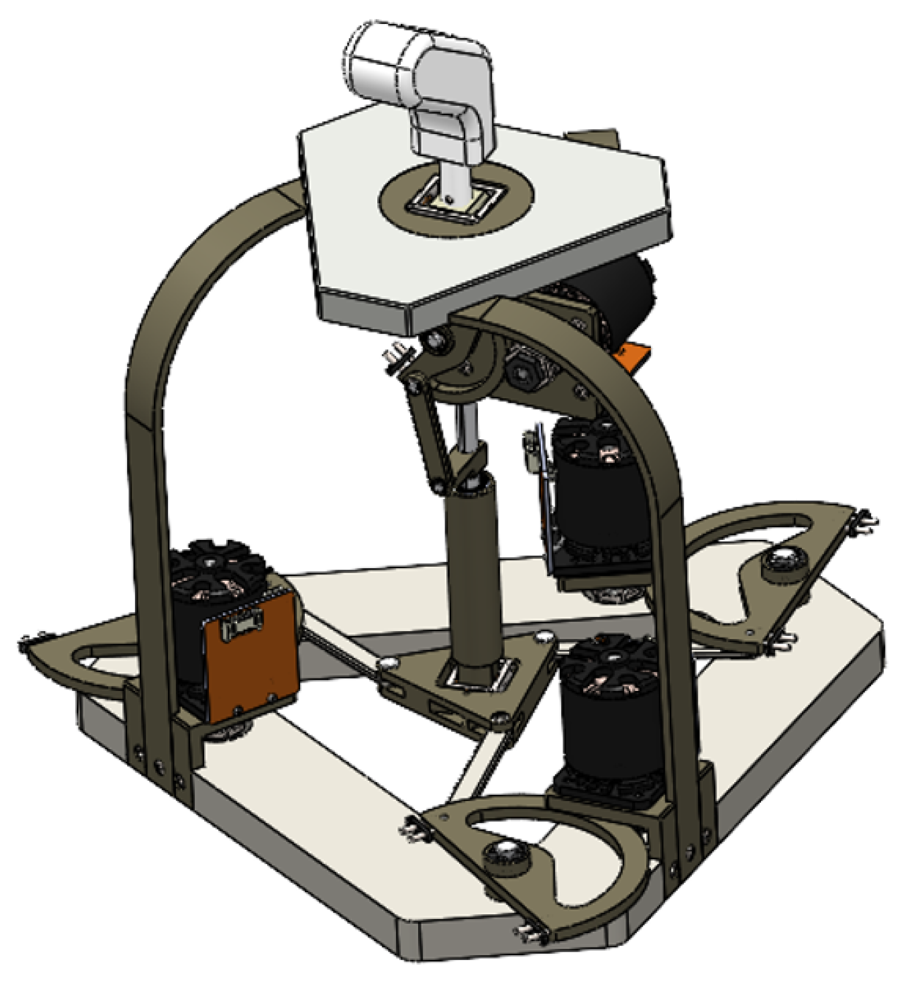
2. The New Haptic Hybrid Device Description
The innovative hybrid haptic device (abbreviated as nHH), a recently proposed 4-degree-of-freedom (4-DoF) design, consisting of three rotation axes centered around a fixed Center of Rotation (CoR) and one translational axis, is depicted in
Figure 3. The selection of this architectural configuration is driven by two key considerations. Firstly, it accommodates the need for three rotational motions centered around an external COR, which lies outside the device’s mechanical framework. Secondly, it provides a conical workspace.
The nHH device represents a fusion of a parallel kinematic chain and a serial kinematic chain. This association serves a multitude of functions. Firstly, it alleviates the limitations linked to serial architecture setups, where actuators are situated along the joint axes, resulting in augmented moving masses and modifications in dynamic performance. Conversely, the nHH harnesses the benefits inherent to a parallel structure, amplifying both its rigidity, precision and generating the haptic effect.
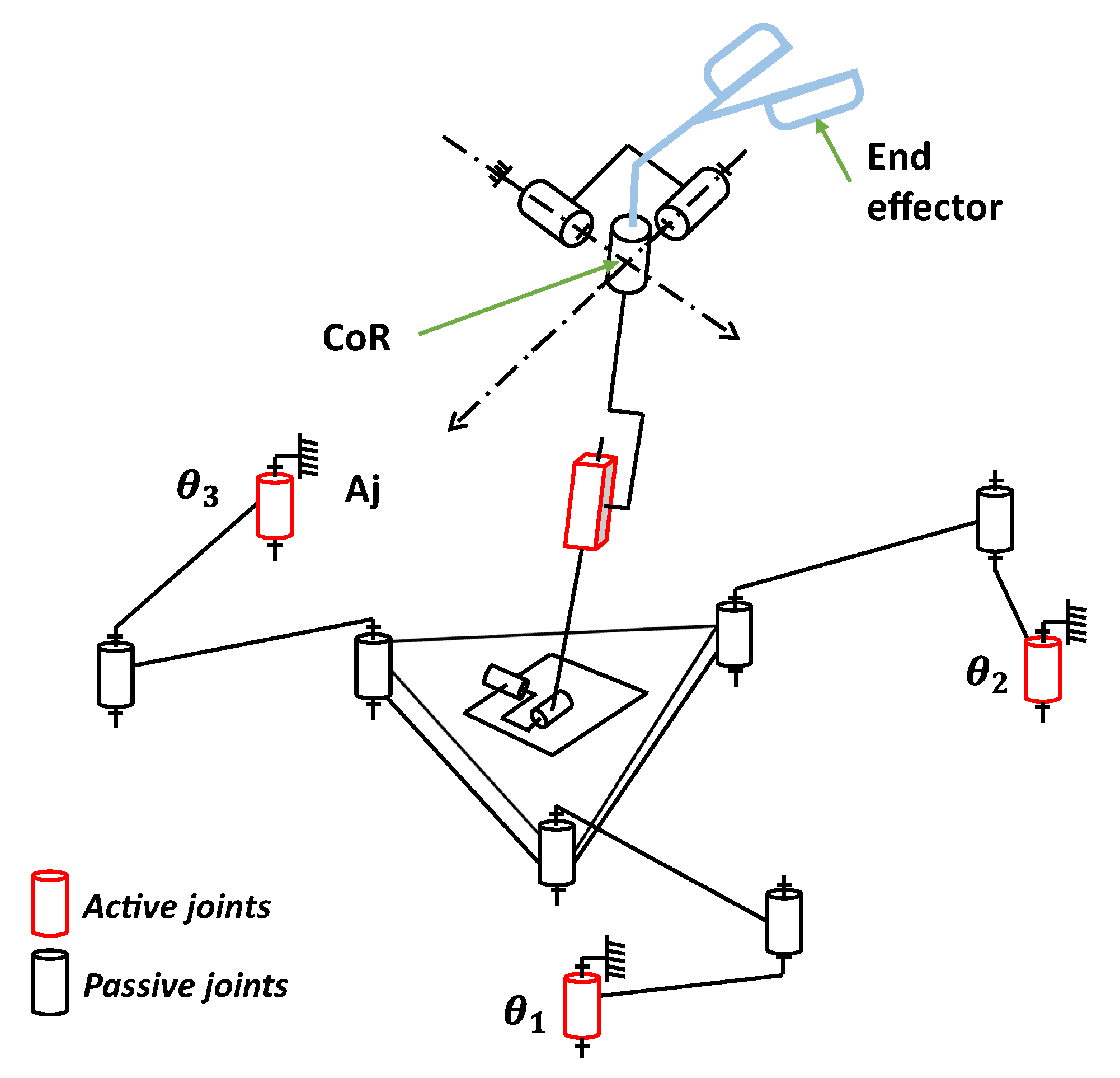
The new device can be defined by two chains, one parallel and one serial. The parallel chain of the nHH device is characterized by a 3-RRR parallel planar manipulator [
17]. This manipulator consists of three identical kinematic legs that connect a mobile platform to a base. Each of these legs is comprised of an actuated revolute joint, followed by two revolute joints designed to connect to the platform as depicted in
Figure 4a.
The center of the joint where the links of the
i-th leg meet is referred to as
(as shown on
Figure 4). The lengths of the links in the
i-th leg are denoted as
(for link
) and
(for link
). The active as well as the passive revolute joints are denoted by
and
, respectively, with
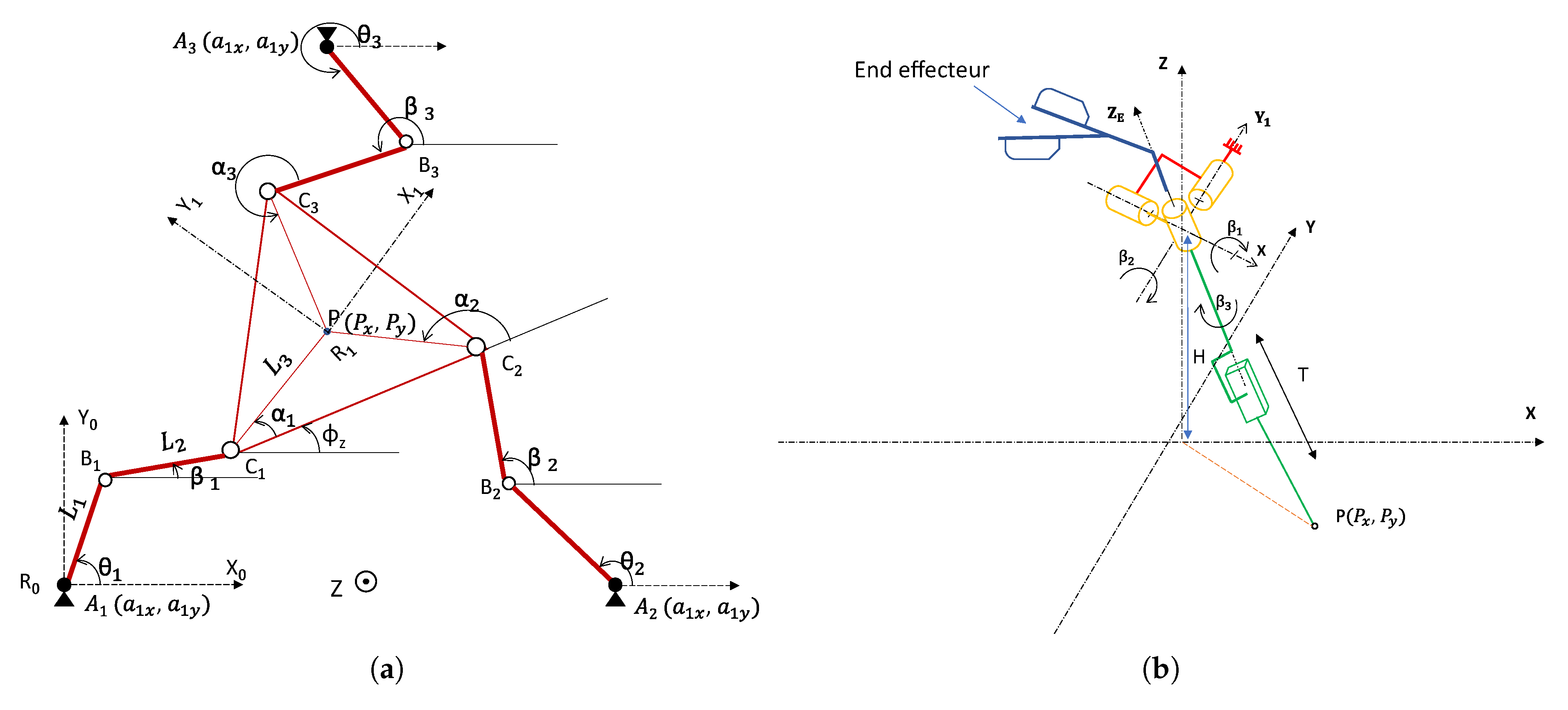
i = 1, 2, 3. The position of the mobile platform is precisely determined by the coordinates of point
(see
Figure 4) within the fixed reference frame
, while its orientation is defined by the angle
, which represents the rotation angle about the Z axis of the mobile platform frame
with respect to the fixed frame
as illustrated in
Figure 4a.
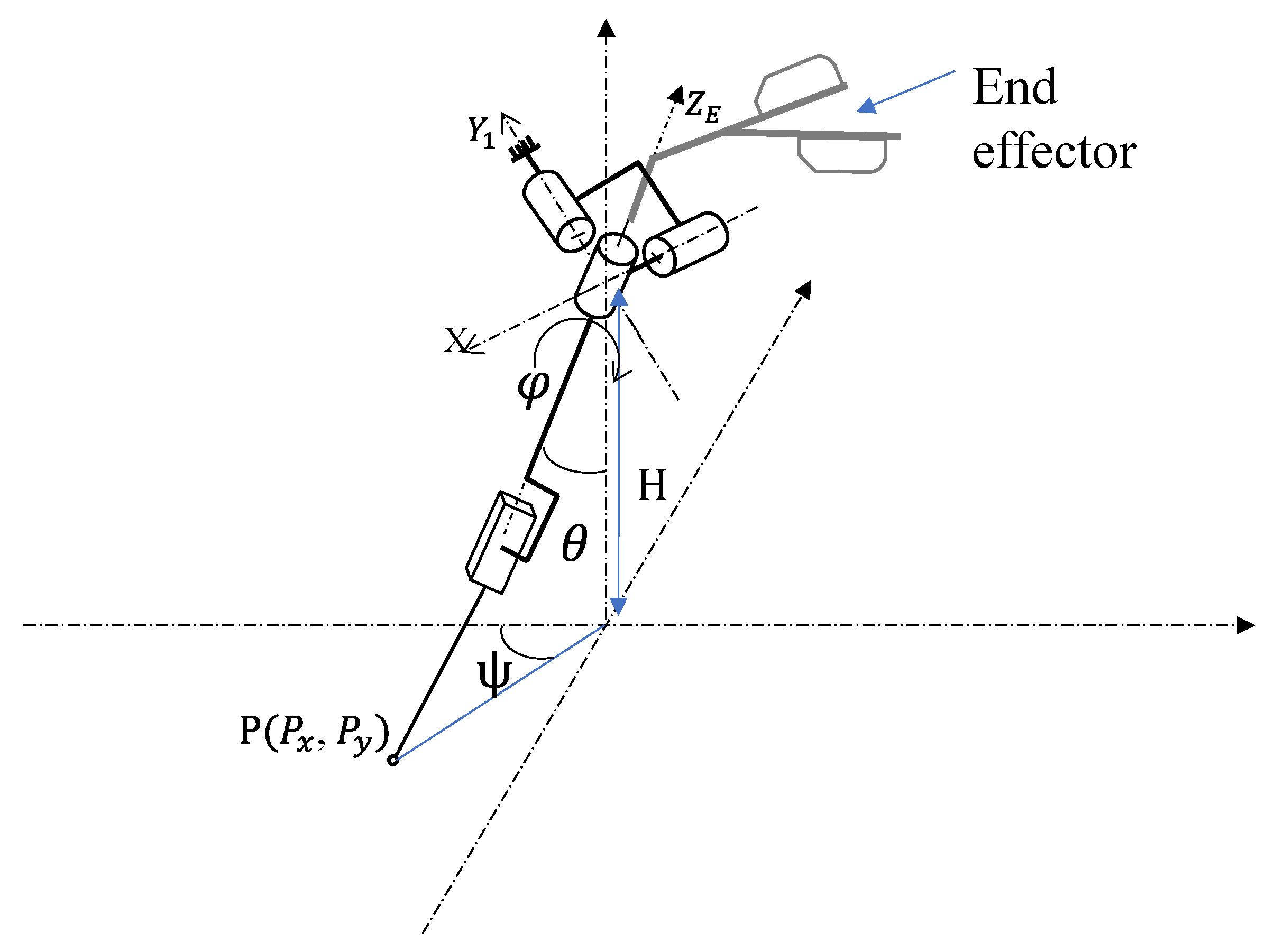
The serial chain of the proposed nHH device comprises a universal joint, functioning as a Center of Rotation (CoR), a revolute joint for self-rotation, and a prismatic joint that governs the linear displacement designated as “T”. As illustrated in
Figure 4b, the orientations of this serial chain are precisely defined using Euler angles, involving three distinct rotations within three-dimensional space.
2.1. Inverse Kinematic Model of the nHH Device
The position and orientation of the mobile platform in the parallel chain are interdependent with the orientation of the serial chain. As a result, Equation (
1) defines the relationships between the Cartesian coordinates of point P, the orientation of mobile platform
, and the end-effector orientation (
,
,
).
Figure 5 serves as an illustrative guide showcasing how these interconnections are built:
In this context, H represents the distance separating the center of the rotation and the plan of the mobile platform.
The inverse kinematic model, used to derive the values of the active joints based on the position and orientation of the mobile platform, can be expressed as follows:
where
,
and
are detailed in [
18].
2.2. Forward Kinematic Model of the nHH Device
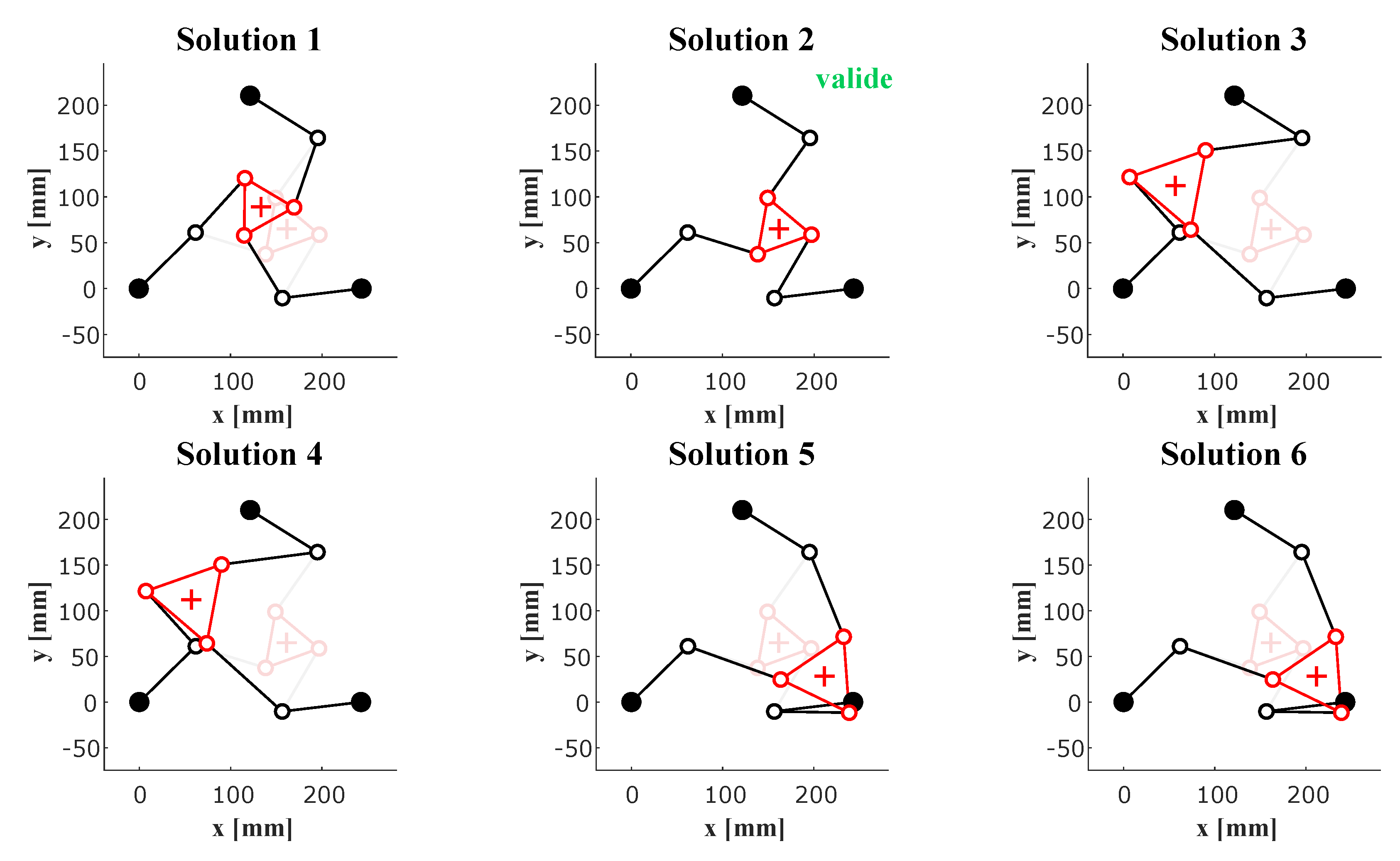
The FKM is determined by the orientation of the end effector, which is connected to the serial chain, given a specific configuration of the actuated joints. Each motor within the manipulator is equipped with an encoder, which calculates the position values for each active joint. With these data in hand, it becomes possible to analytically compute the position and the orientation of the mobile platform within the parallel chain. This calculation is performed using a MATLAB code. One significant limitation of this method is that it yields six possible solutions, necessitating the identification of the most appropriate one that accurately represents the actual configuration as shown in
Figure 6. Then, based on Equation (
1), we can determine the orientation of the end effector. As mentioned, this method has several drawbacks since it is almost impossible to use it in real-time applications such as in our case.
Selecting the working mode from the different configurations presented in
Figure 6 involves considering the kinematic structure, task requirements, workspace constraints and performance criteria. Also, ensure that the manipulator can reach all the required positions and orientations for the task. When choosing a working mode for the nHH, careful consideration of the task-specific requirements and the manipulator’s kinematic capabilities is essential. Simulation and prototyping play a crucial role in validating the chosen working mode before the manipulator is deployed for actual tasks.
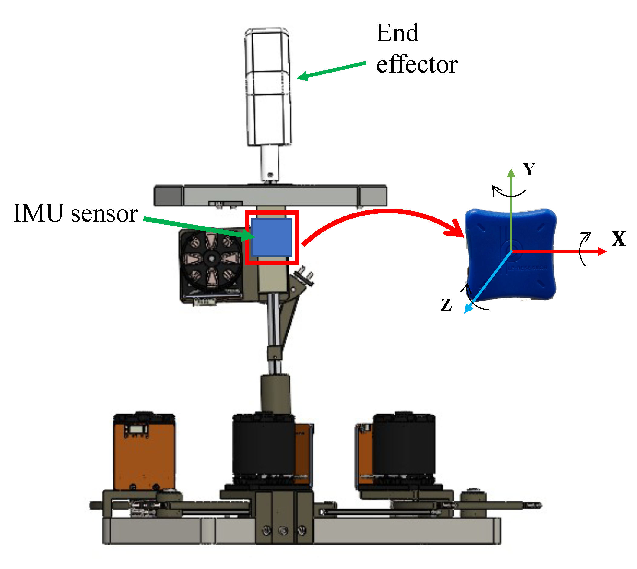
2.3. Forward Kinematic Model Using an Extra Sensor
In order to overcome the problem of FKM resolution, Meskini et al. proposed in [
16] the use of an extra sensor (IMU) placed on the serial chain of the device as shown in the
Figure 7.
The used IMU is a 9-axis inertial measurement unit with a resolution less than
. An accuracy of
and
for static and dynamic measurements, respectively. By obtaining the data from the encoders within the motors to determine the values of the active joints and the information about the orientation of the end effector provided by the IMU, we can accurately establish the FKM of the device. This method yields a single, unambiguous solution of the FKM. To ascertain the correct solution, a comparison study is made [
16] between the self-rotation of the mobile platform given by the IMU and the analytic FKM. This comparison helps identify the most accurate solution.
The used algorithm to compute the FKM, based on the proposed method, is described as follows [
16]:
Read the IMU quaternion (, , , ) for different orientations of the end effector, i = 1, 2, …, n
Transform the IMU quaternion to Euler angles (, , ).
Compute (
,
,
) using Equation (
1).
Read the angular values of the active joints.
Compute the mobile platform position and orientation (, , ) using the analytic model of the FKM.
Compute the FKM of the nHH.
The Euler angles can be obtained from the quaternion provided by the IMU by using Equation (
3):
2.4. Kinematic Model of the nHH
The velocity of the end effector can be expressed using the universal joint velocities (
,
,
) presented in
Figure 4b as follows [
15]:
Using the Euler angles (
,
,
) with the ZXZ convention, we can describe the orientation of the end effector in the workspace. The end-effector angular velocity can be expressed as shown in Equation (
5):
Or, from Equations (4) and (6), we can obtain:
where,
with,
where,
Using this result, the Jacobian matrix
is expressed by:
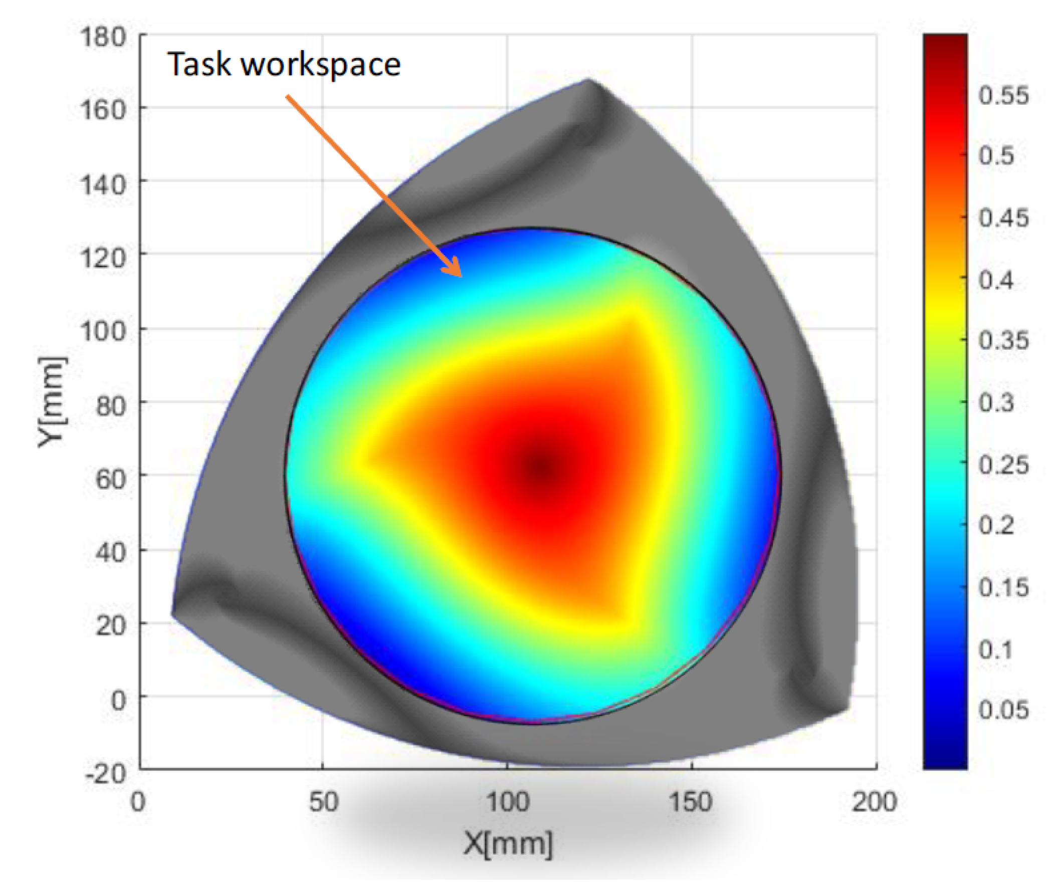
For the purpose of evaluating the kinematic performance of the nHH device, we propose to use the dexterity criterion [
19] denoted as
, which is defined by the inverse of the conditioning number of the Jacobian matrix.
The dexterity distribution of the serial chain in the plane (, ) is higher than 0.5. We can conclude that the nHH device has no singularity in its workspace.
For the parallel chain of the nHH device, which is based on the 3-RRR parallel planar manipulator, the dexterity distribution is illustrated in
Figure 8. This manipulator was optimized in order to perform in a workspace almost with no singular configurations.
The workspace of the nHH device was determined based on a motion capture system that records the gestures of a surgeon. The analysis presented in [
20] suggests that the minimally invasive surgical procedures require tools with four specific degrees of freedom: three rotational movements and one translational movement. According to this research, the tool’s range of motion is confined within a cone shape. This cone has a maximum vertex angle of
, indicating the extent of rotational movements, and allows for a translation of 112 mm along the tool’s axis direction, signifying the maximum straight-line movement the tool can achieve. These findings are essential in the realm of medical robotics, particularly in robotic surgery, as they define the precise movement and spatial limitations necessary for performing MIS effectively and safely.
The desired task workspace presented in
Figure 8 is defined by the intersection of the cone described by the serial chain and the plane of the parallel planar manipulator, enabling the nHH device to perform in a workspace with almost no singular configurations.
3. Motion Control of the Tele-Operation System: Master–Slave Control
Master–slave control in tele-operation systems entails a human operator (master) manipulating a device or system (slave) from a remote location through a designated interface. The master device, often a joystick or haptic controller, captures the operator’s inputs, which are then transmitted to the slave device. A dependable communication system is crucial for real-time signal transmission, and feedback mechanisms, such as visual or force feedback, enhance the operator’s situational awareness. Safety measures, adaptability, and control algorithms, such as PID controllers, contribute to the system’s reliability. The user interface is designed for an intuitive experience, and considerations for the remote environment, including latency and stability, are paramount. This approach finds applications in various fields, from hazardous environment exploration to space missions, enabling precise and immersive control over remote systems.
One of the applications of this technology is the minimally invasive surgery known also as tele-robotics-assisted surgery or tele-robotic surgery. The principal aim of this technology is to use position commands from the surgeon’s console, often referred to as the “master” robot in tele-operation terminology, to control the patient-side surgical robot, typically termed the “slave” robot. Presently, surgeons conducting tele-robotic surgery have the capability to closely monitor the surgical procedure through three-dimensional visual observation, enhancing their precision and control during surgery.
The primary function of the master system is to accurately replicate the surgeon’s movement, transmit it to the slave system, and, moreover, transmit the haptic feedback to the surgeon.
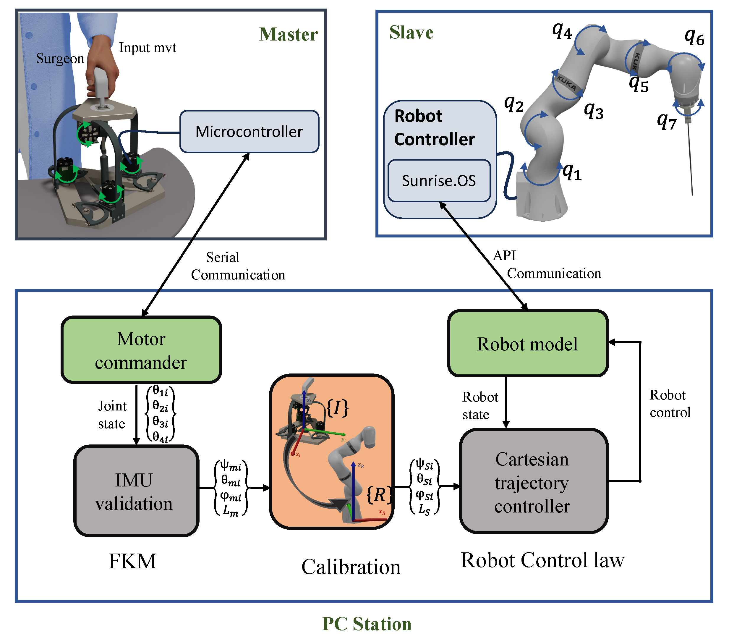
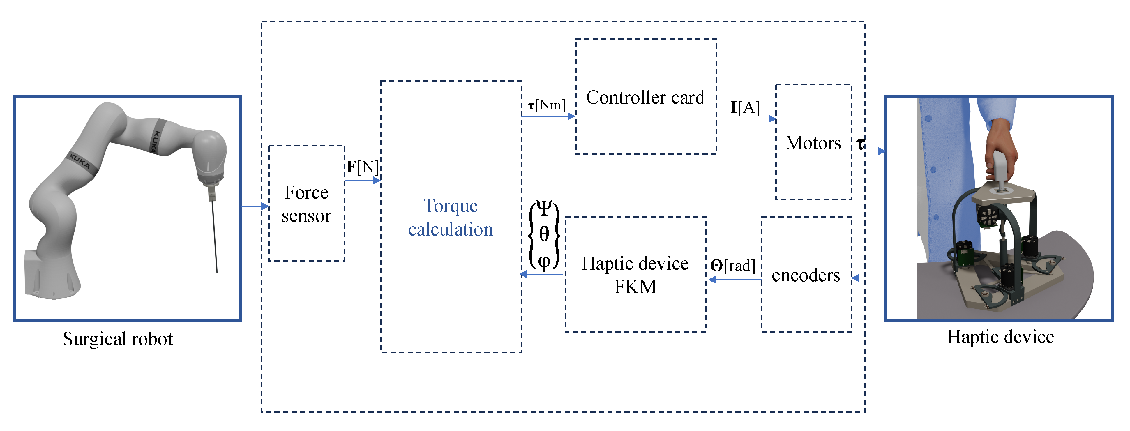
The tele-operation control diagram is shown in
Figure 9. As the surgeon manipulates the nHH device, a microcontroller embedded within the interface detects the active joint angles (
,
,
,
) and transmits this information to a PC station through serial communication protocols. Upon reception, a motor controller node decodes these data and feeds them into a real-time forward kinematic model (FKM), an enhanced method leveraging IMU sensor technology elucidated in
Section 2.3. This FKM solution, derived from the nHH device, is initially expressed in the interface base frame and subsequently necessitates recalibration for proper alignment within the robot’s local workspace, achieved through a dedicated calibration node.
On the other hand, the determined orientations are relayed to the robot’s control system as the targeted trajectory orientation for the medical instrument. A Cartesian trajectory controller loop is deployed to compute the reference angles required for the slave robot’s active joints. These calculated values are then transmitted to the slave controller via an API communication interface, enabling precise control over the motion of each axis with a frequency of 500 Hz. This operational setup ensures real-time tele-operation with minimal latency, facilitating highly responsive control over the system.
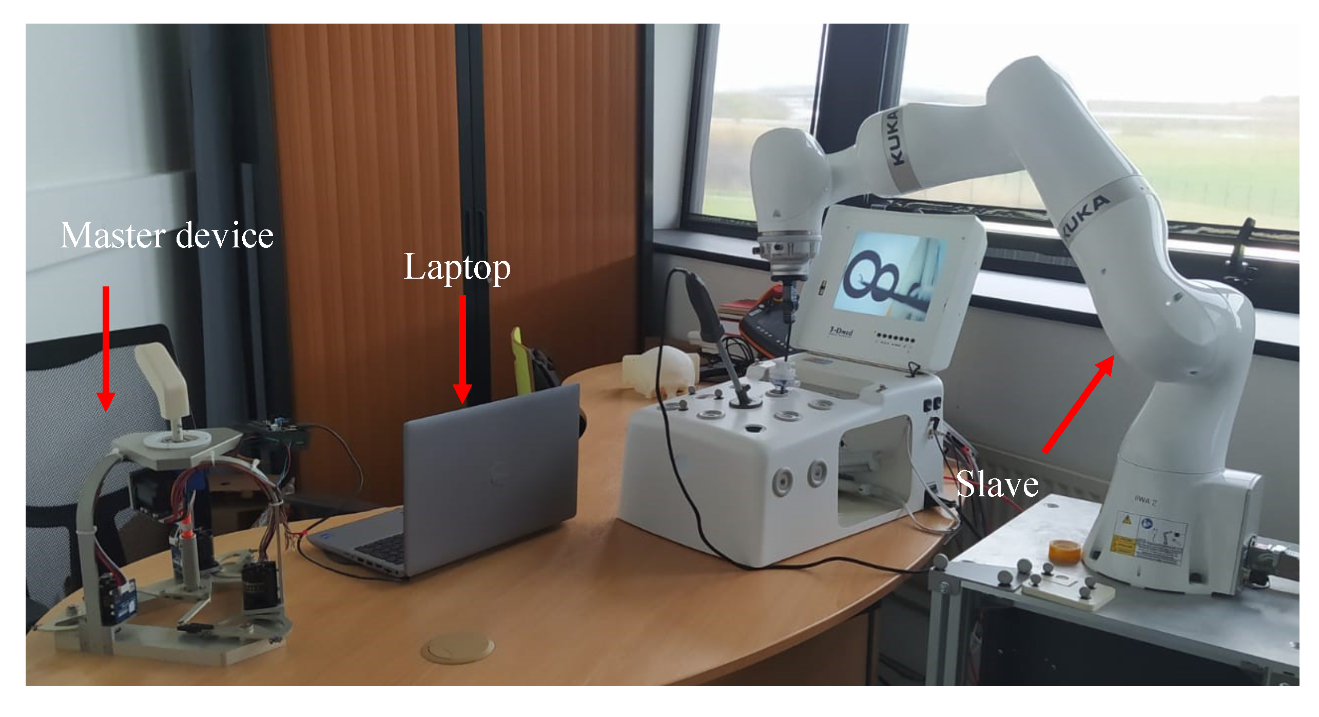
3.1. Experimental Setup
The experimental test bench depicted in
Figure 10 is built around the nHH device, which includes four brushless motors developed by Simplex Motions (model SC040) (Simplex Motion AB. Banehagsliden, Gothenburg, Sweden). Each of these motors is connected to a capstan mechanism with a 4:1 ratio, allowing it to reduce speed while increasing torque. The motors are all interconnected with a power card, which is subsequently connected to a laptop. This setup allows the retrieval of angular position values from the motors and facilitates the calculation of the FKM of the device. This latter is then utilized as a target for the motion control of the slave robot. The motion planning is formulated using a sophisticated control algorithm that enables the robot end-effector’s position and orientation to replicate the real-time movement captured by the nHH.
3.2. Experimental Tests
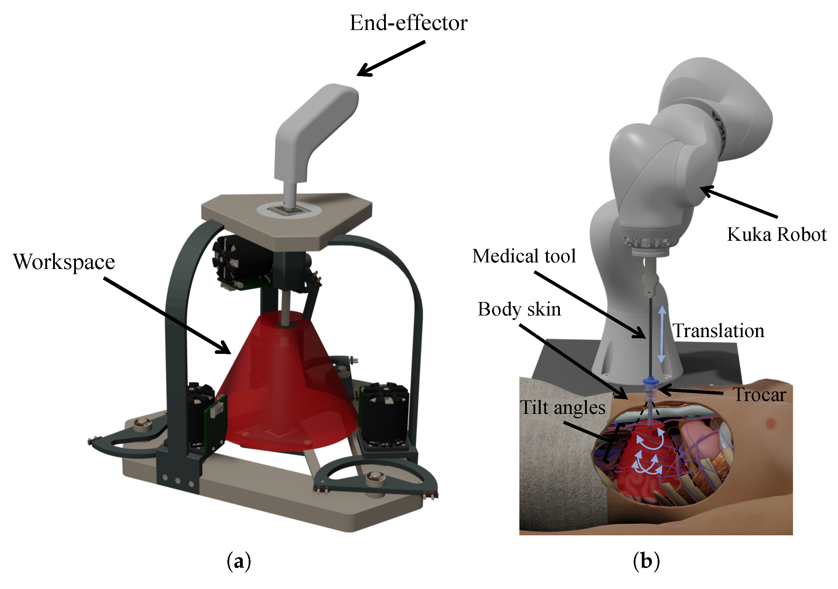
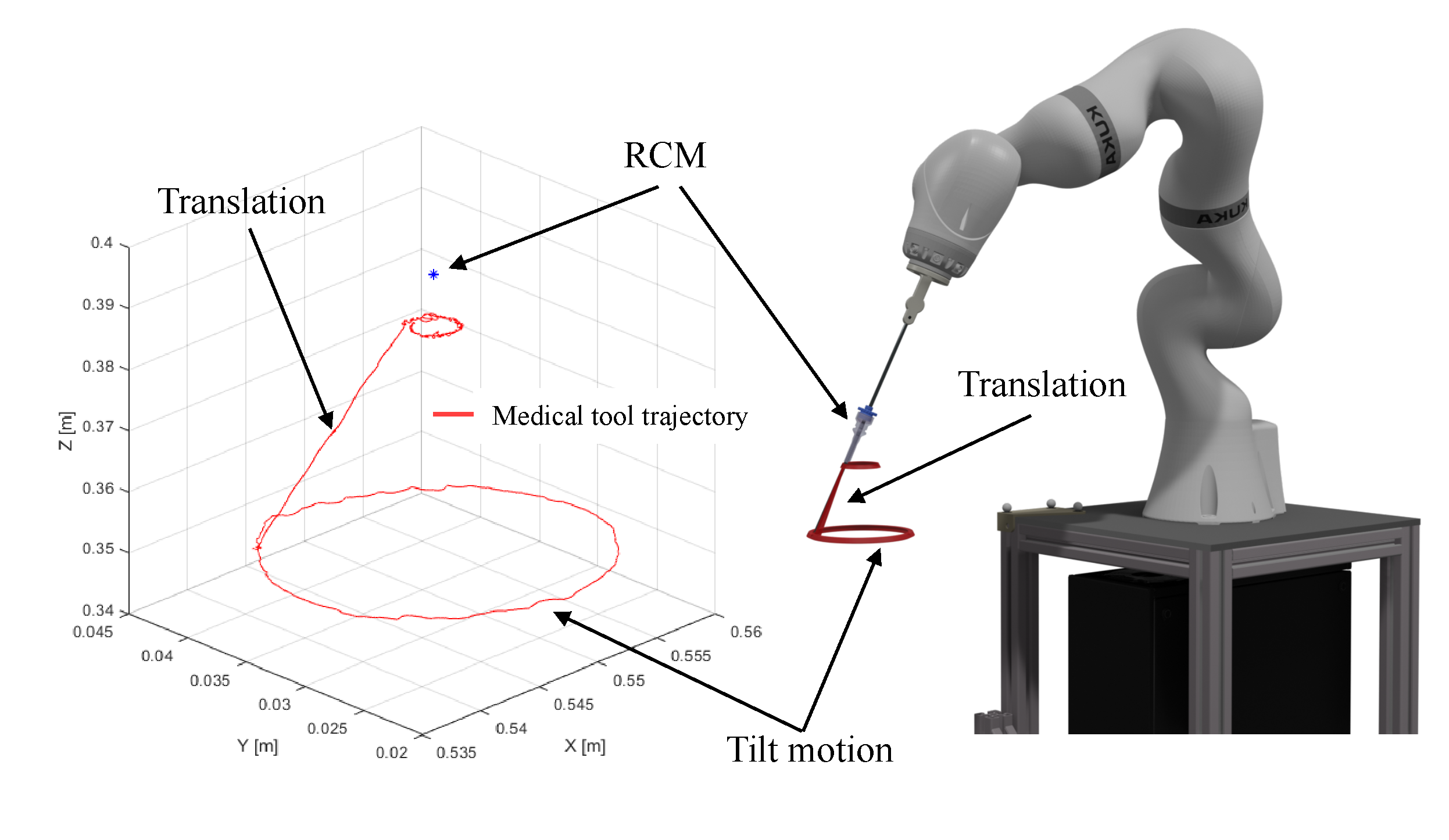
The collaborative robot KUKA iiwa serves, in this experimental application, to operate a surgical task within a limited workspace. The abdominal cavity of the patient is accessed through a small incision to insert the instruments required for the operation. The use of this constrained workspace promotes the creation of a remote center of motion (RCM), enabling four degrees of freedom: three rotations and one translation as depicted in
Figure 11a.
According to the analysis of surgical gestures reported in [
20], the MIS procedure necessitates four degrees of freedom: three rotational movements and one translational motion. This implies that the workspace of the master device can be described as a cone as presented in
Figure 11b.
In order to validate our master–slave platform, the user manipulates the nHH device in various directions in its workspace while measuring both the master and slave orientations and translation.
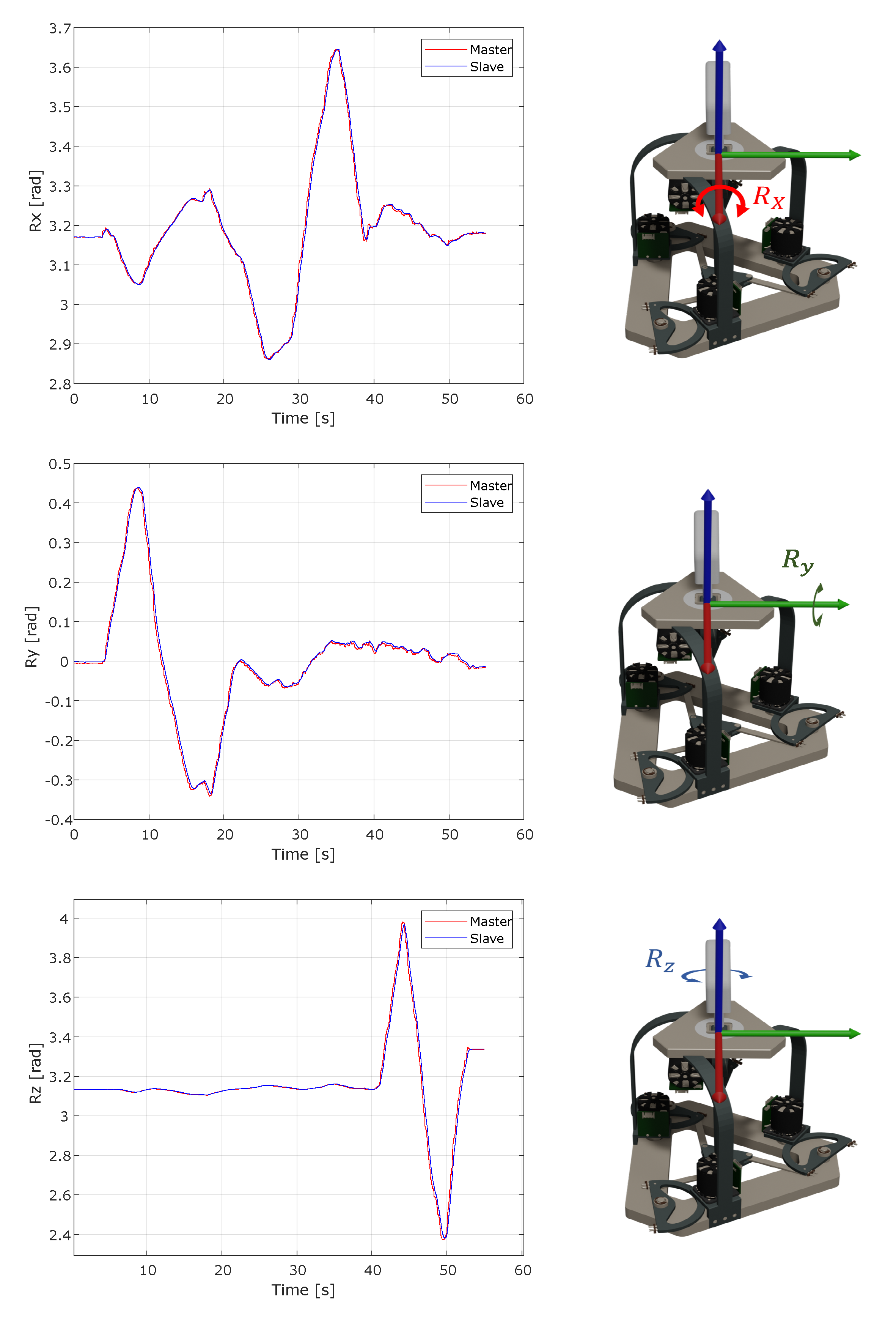
In order to verify the performance of the haptic interface and robot workspaces, we conducted an experiment where we manually manipulated the master device’s end effector within the three primary orientations of the interface’s frame. Then, we compared the resulting poses of the robot’s tool center point (TCP).
Figure 12 depicts the three primary rotations along the X, Y, and Z axes. This process of the main rotation variation along the nHH interface is coupled with the robot tool movement. A calibration process is used to project the interface data in the robot workspace and align them with the tool orientation, which is subsequently used as a target in the control law. As seen in the master/slave data, the robot’s tool center point successfully tracks the orientations acquired by the master interface’s forward kinematics model. The orientation graphs show that the slave robot replicates the directions obtained from the surgeon’s motions via the haptic interface with a maximal error of 0.017 radians.
In order to take advantage of all four degrees of freedom provided by the nHH system, we conducted a trajectory as depicted in
Figure 13. This trajectory involved two circular motions in separate planes within the workspace, connected by a translation trajectory along a selected axis. To assess the precision of both the master and slave systems and the implemented approach, we successfully represented the tilt movements of the two manipulators.
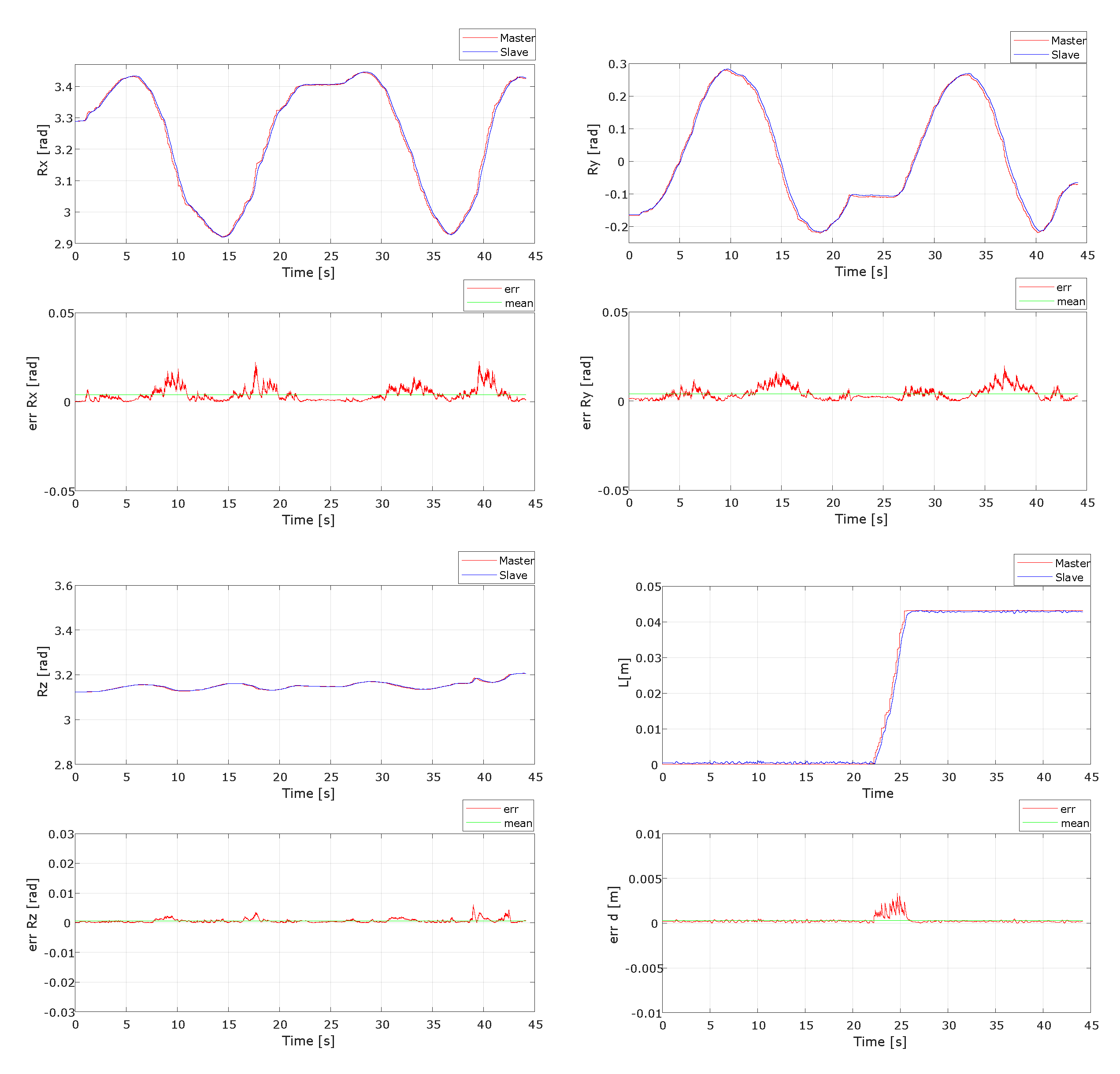
The graphs presented in
Figure 14 demonstrate that the slave robot reproduces the same trajectory captured by the nHH interface. The platform responds to the operator’s instructions using the nHH data sent to the robot and follows the same trajectory. In order to assess the precision of the system and the efficacy of the implemented method, an evaluation of the error between the master input, computed by the FKM of the nHH interface, and the feedback received from the slave robot is presented in
Table 1. These results reflect both the system’s inherent latency as well as the complexity of the calculation involved.
4. Haptic Control
Haptic control in robotics [
21,
22] refers to the utilization of specialized devices, like haptic interfaces and exoskeletons, to enable real-time manipulation and interaction with robots through the sense of touch. These gadgets offer users force and tactile feedback, empowering them to sense and manage distant or virtual items. Within the realm of robotics, haptic control fulfills numerous crucial functions. The integration of haptic control greatly enhances robot-assisted surgery by enabling surgeons to perceive tissue resistance and texture through haptic feedback. This heightened sense of touch proves invaluable during minimally invasive procedures, enhancing precision and enabling more accurate movements. As a result, surgeries become less invasive, promoting faster patient recovery times.
In our case, the nHH device serves as the master component of a master–slave platform, functioning to command the actions of the slave robot and provide force feedback when the slave robot interacts with its external environment while performing MIS surgery. The design of the nHH device is based on the mechanical solution that incorporates a capstan mechanism coupled with a simplex DC motor. The DC motors deliver a nominal torque of 0.8 [Nm]. The force control schema is illustrated in
Figure 15. The force applied on the surgical robot is measured using a force sensor. Then, we calculate the actuated torques using the following Equation (
13):
with,
F: Force applied on the surgical robot.
: Transpose of the Jacobian matrix of the master device.
: Actuated joints torques.
: Torque vector to compensate for the dynamic and static effects of the master device.
Finally, the calculated torques are transmitted to the motors of the haptic device in order to give the force feedback to the surgeon.
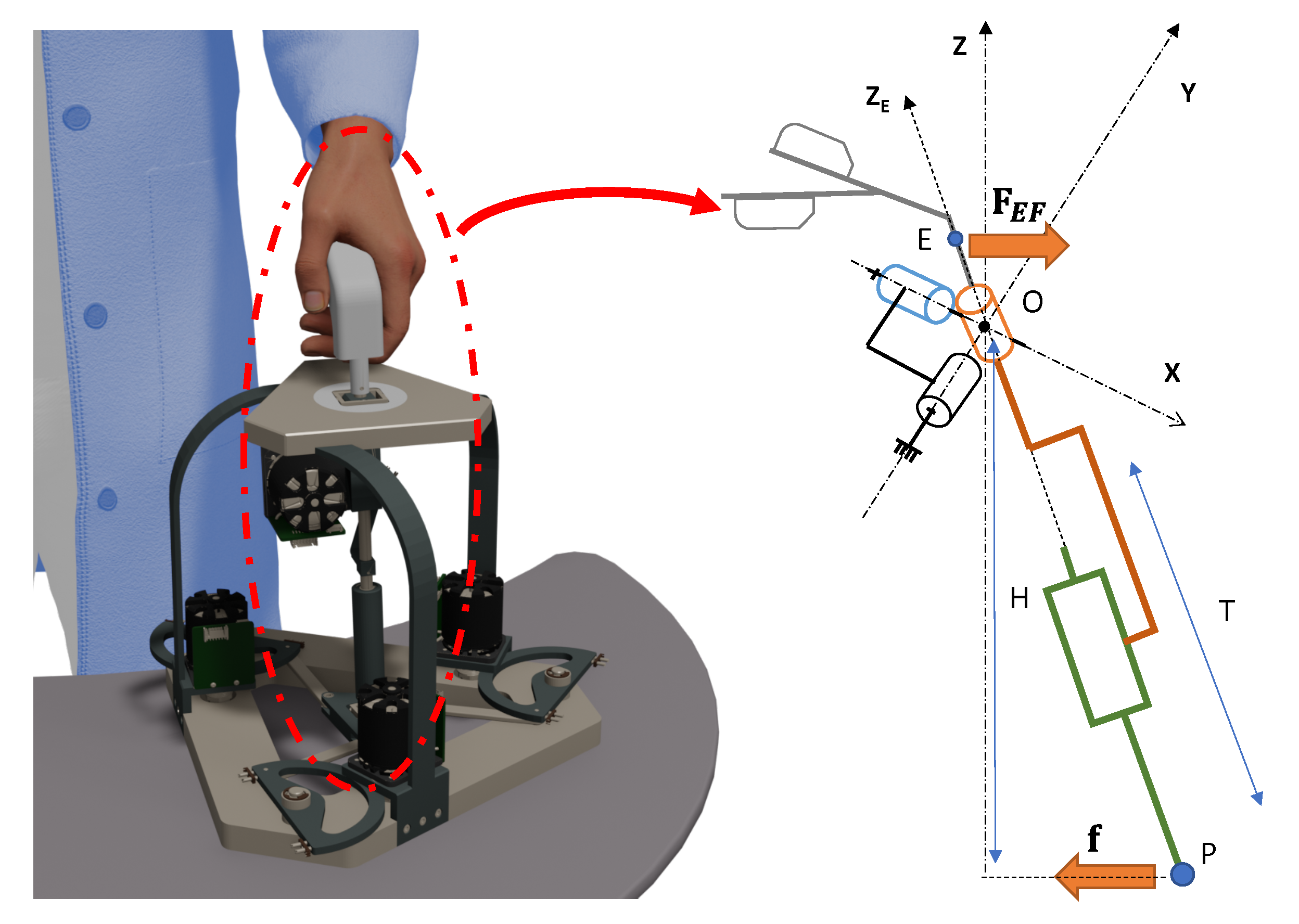
Figure 16 shows the relation between the force applied on the mobile platform of the nHH device and its end effector.
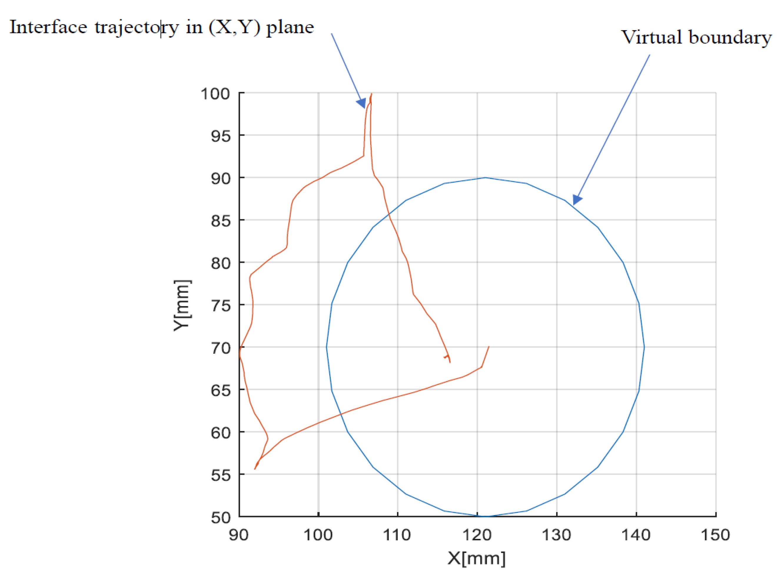
The validation of the force feedback consists of calculating the force applied on the end effector while manipulating the nHH in real-time experiments as shown in
Figure 17. As long as the nHH is manipulated within the desired boundary, the force feedback is zero. Once we try to exceed the boundary, the force applied on the end effector increases.
The force
f is defined by the following relation:
with,
f: Force applied on the parallel mobile platform, .
: Transpose of the Jacobian matrix of the 3RRR planar parallel manipulator.
: Actuated joint torques (, , ).
Knowing the actuated joints torque in each motor, we can determine the force using Equation (
14). Then, the relation between the two efforts is denoted by Equation (
15):
with,
For
=
=0, the relation between the applied effort
and the effort
f is given by the equations below:
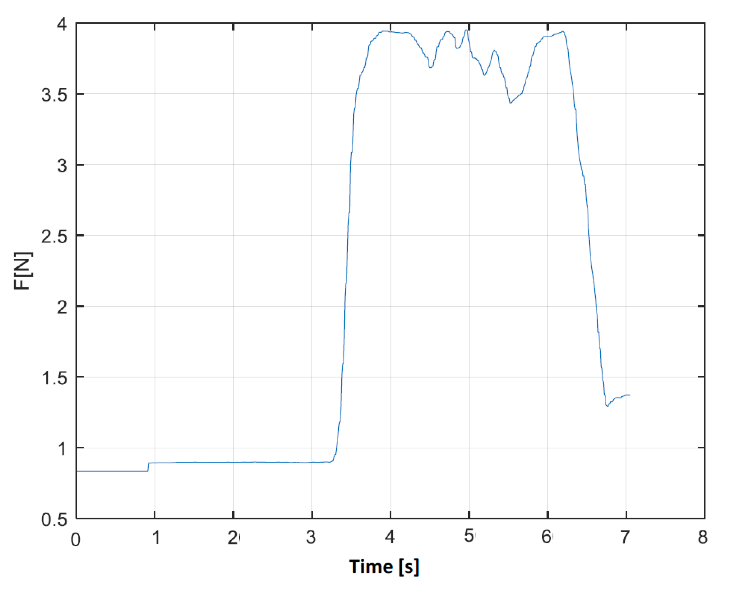
Figure 18 gives a visual representation of the evolution of the force applied on the end effector. Once we cross the boundary, a significant augmentation of the force is applied, which proves the efficiency of the implemented approach.
According to the results presented above, it was proven that the master–slave platform is suitable for the surgical task, enabling the surgeons to perform complex procedures with remarkable dexterity and accuracy, particularly in minimally invasive surgeries, where small incisions and precise movements are crucial.
5. Conclusions
In this paper, we introduced a master–slave platform composed of a new hybrid haptic device and KUKA iiwa robot, which are designed to be used in laparoscopic surgery. The haptic device is based on an association of a parallel and a serial chain characterized by a fixed Center of Rotation and 4 degrees of freedom. The kinematic model of the hybrid parallel robot was presented as well as the kinematic performance distribution over its workspace. The optimal parameters were considered in order to ensure a task workspace with no singular configurations.
Experiments were conducted in order to validate the motion control of the slave–master control. A scheme of this control was presented and validated in a real-time tests. The provided results prove the efficiency of the implemented approach. The error of the motion does not exceed 0.0041 radians for tilt movements, while the mean error for the insertion is very low, which proves the capability of the system.
A control scheme in order to provide the haptic feedback based on the calculation of the FKM of the nHH device was proposed and implemented also. Simulations and experiments were also carried out in order to validate the haptic feedback.
Nevertheless, this work presents some limitations: for instance, the IMU sensor must be re-charged every 6 h, which means that until this point, our platform is not adequate for long operations. In future work, a force sensor will be installed on the slave, and experiments will be conducted to validate the force feedback in real-time applications. Also, the master–slave platform will be tested by qualified surgeon in order to evaluate the performance of the system in a real application.
Author Contributions
Conceptualization, M.M. and A.T.; methodology, M.M., A.T., M.A.L. and H.S.; software, M.M. and A.T.; validation, M.M., A.T. and J.S.; formal analysis, M.A.L. and H.S.; investigation, M.M., A.T. and M.A.L.; resources, M.A.L.; data curation, M.M. and A.T.; writing—original draft preparation, M.M., A.T., M.A.L. and H.S.; writing—review and editing, M.M., A.T., M.A.L., A.M. and H.S.; visualization, M.A.; supervision, M.A.L. and A.M.; project administration, S.Z. All authors have read and agreed to the published version of the manuscript.
Funding
This research received no external funding.
Data Availability Statement
The datasets generated during and/or analyzed during the current study are available from the corresponding author upon reasonable request.
Conflicts of Interest
The authors declare no conflict of interest.
References
- Kansal, S.; Zubair, M.; Suthar, B.; Mukherjee, S. Tele-operation of an industrial robot by an arm exoskeleton for peg-in-hole operation using immersive environments. Robotica 2022, 40, 234–249. [Google Scholar] [CrossRef]
- Ellis, R.E.; Ismaeil, O.M.; Lipsett, M. Design and evaluation of a high-performance prototype planar haptic interface. In Proceedings of the 1993 ASME WinterAnnual Meeting, New Orleans, LA, USA, 28 November–3 December 1993; Volume 49, pp. 55–64. [Google Scholar]
- MacLean, K.E. Designing with haptic feedback. In Proceedings of the Proceedings 2000 ICRA. Millennium Conference. IEEE International Conference on Robotics and Automation. Symposia Proceedings (Cat. No.00CH37065), San Francisco, CA, USA, 24–28 April 2000; Volume 1, pp. 783–788. [Google Scholar]
- Kucuk, S.; Gungor, B.D. Inverse kinematics solution of a new hybrid robot manipulator proposed for medical purposes. In Proceedings of the 2016 Medical Technologies National Congress (TIPTEKNO), Antalya, Turkey, 27–29 October 2016; pp. 1–4. [Google Scholar]
- Gosselin, F.; Jouan, T.; Brisset, J.; Andriot, C. Design of a wearable haptic interface for precise finger interactions in large virtual environments. In Proceedings of the First Joint Eurohaptics Conference and Symposium on Haptic Interfaces for Virtual Environment and Teleoperator Systems. World Haptics Conference, Pisa, Italy, 18–20 March 2005; pp. 202–207. [Google Scholar]
- Zidane, I.F.; Khattab, Y.; Rezeka, S.; El-Habrouk, M. Robotics in laparoscopic surgery—A review. Robotica 2023, 41, 126–173. [Google Scholar] [CrossRef]
- Okamura, A.M. Haptic feedback in robot-assisted minimally invasive surgery. Curr. Opin. Urol. 2009, 19, 102. [Google Scholar] [CrossRef] [PubMed]
- van den Bedem, L.; Hendrix, R.; Rosielle, N.; Steinbuch, M.; Nijmeijer, H. Design of a minimally invasive surgical teleoperated master-slave system with haptic feedback. In Proceedings of the 2009 International Conference on Mechatronics and Automation, Changchun, China, 9–12 August 2009; pp. 60–65. [Google Scholar]
- Kong, X.; Gosselin, C.M. Type synthesis of three-degree-of-freedom spherical parallel manipulators. Int. J. Robot. Res. 2004, 23, 237–245. [Google Scholar] [CrossRef]
- Tanev, T.K. Kinematics of a hybrid (parallel–serial) robot manipulator. Mech. Mach. Theory 2000, 35, 1183–1196. [Google Scholar] [CrossRef]
- Xu, P.; Cheung, C.F.; Wang, C.; Zhao, C. Novel hybrid robot and its processes for precision polishing of freeform surfaces. Precis. Eng. 2020, 64, 53–62. [Google Scholar] [CrossRef]
- Ennaiem, F.; Chaker, A.; Sandoval, J.; Mlika, A.; Romdhane, L.; Bennour, S.; Zeghloul, S.; Laribi, M.A. A hybrid cable-driven parallel robot as a solution to the limited rotational workspace issue. Robotica 2023, 41, 850–868. [Google Scholar] [CrossRef]
- Carbone, G.; Ceccarelli, M. A stiffness analysis for a hybrid parallel-serial manipulator. Robotica 2004, 22, 567–576. [Google Scholar] [CrossRef]
- Saafi, H.; Laribi, M.A.; Zeghloul, S. Design of a 4-DoF (degree of freedom) hybrid-haptic device for laparoscopic surgery. Mech. Sci. 2021, 12, 155–164. [Google Scholar] [CrossRef]
- Meskini, M.; Saafi, H.; Mlika, A.; Arsicault, M.; Zeghloul, S.; Laribi, M.A. Development of a novel hybrid haptic (nHH) device with a remote center of rotation dedicated to laparoscopic surgery. Robotica 2023, 41, 3175–3194. [Google Scholar] [CrossRef]
- Meskini, M.; Saafi, H.; Mlika, A.; Arsicault, M.; Sandoval, J.; Zeghloul, S.; Laribi, M.A. Forward Kinematic Model Resolution of a Hybrid Haptic Device Using an Inertial Measurement Unit. In New Trends in Medical and Service Robotics; Springer: Cham, Switzerland, 2023; pp. 289–297. [Google Scholar]
- Staicu, Ş. Kinematics of the 3-RRR planar parallel robot. UPB Sci. Bull. Ser. D 2008, 70, 3–14. [Google Scholar]
- Kucuk, S. Energy minimization for 3-RRR fully planar parallel manipulator using particle swarm optimization. Mech. Mach. Theory 2013, 62, 129–149. [Google Scholar] [CrossRef]
- Gosselin, C.; Angeles, J. A global performance index for the kinematic optimization of robotic manipulators. J. Mech. Des. 1991, 113, 220–226. [Google Scholar] [CrossRef]
- Nisar, S.; Endo, T.; Matsuno, F. Design and kinematic optimization of a two degrees-of-freedom planar remote center of motion mechanism for minimally invasive surgery manipulators. J. Mech. Robot. 2017, 9, 031013. [Google Scholar] [CrossRef]
- Cortesao, R.; Zarrad, W.; Poignet, P.; Company, O.; Dombre, E. Haptic control design for robotic-assisted minimally invasive surgery. In Proceedings of the 2006 IEEE/RSJ International Conference on Intelligent Robots and Systems, Beijing, China, 9–15 October 2006; pp. 454–459. [Google Scholar]
- Katsura, S.; Iida, W.; Ohnishi, K. Medical mechatronics—An application to haptic forceps. Annu. Rev. Control 2005, 29, 237–245. [Google Scholar] [CrossRef]
| Disclaimer/Publisher’s Note: The statements, opinions and data contained in all publications are solely those of the individual author(s) and contributor(s) and not of MDPI and/or the editor(s). MDPI and/or the editor(s) disclaim responsibility for any injury to people or property resulting from any ideas, methods, instructions or products referred to in the content. |
© 2024 by the authors. Licensee MDPI, Basel, Switzerland. This article is an open access article distributed under the terms and conditions of the Creative Commons Attribution (CC BY) license (https://creativecommons.org/licenses/by/4.0/).

 ,
, 


