1. Introduction
Currently, ninety-eight percent of the manufacturing industry in Mexico is classified as small- and medium-sized enterprises (SMEs) [
1,
2], a situation very similar to what is occurring in Europe [
3] and Japan [
4] with more than ninety percent. These types of companies can benefit from the advantages of adopting I4.0; that is, they can optimize production times, flexibility in manufacturing, improve the quality of manufacturing processes, develop smart products, and have greater control of production systems. However, they require support on the path of digitalization (as the adoption of I4.0 technology is known in Mexico), which implies factors such as the offer of finance for investment in technology, skills, and a change in vision at managerial level [
5], and warrant that the solutions needed to install I4.0 are user-friendly [
6] to allow full interoperability with current legacy systems and to have a workforce with more technological and soft skills in the I4.0 context [
7]. The industry has identified that the need for more skills in the workforce is considered one of the most significant barriers they face [
8] since hardware and software components are deeply intertwined and interact with each other in diverse ways that may change with context (scenarios or applications) and because of the high complexity associated with the technologies involved: automated robotics, machine learning, big data and analytics, and enterprise resource planning or material requirements planning systems [
3,
9,
10]. In the particular case of Mexico, universities are not meeting this demand, and there is a lack of well-founded educational offers in technologies and skills available in the path of the adoption of I4.0 by SMEs, as well as a null culture of transformation under this new paradigm [
11,
12].
Educational and technological institutions have become a critical point over which efforts should be coordinated concerning the formal training and workforce training required by industry. The training of this workforce in the context of I4.0 is classified into three strategic levels: macroscopic, microscopic, and mesoscopic. The macroscopic strategies’ components are related to institutional directives or government policies, impacting educational models. The microscopic strategies’ components are applications or scenarios of I4.0 technology implementation on which the contents and academic programs are based. Finally, the mesoscopic strategies’ components refer to those with a high-level element as they were raised at the macro level, in this case, frameworks at a conceptual level but connected explicitly with microscopic solutions.
The macroscopic-level strategies involving universities and industry have been implemented to develop I4.0 skills, creating a national system of innovation in manufacturing, and promoting collaborative relationships with a national vision of technological development [
13,
14]. On the other hand, microscopic-level strategies integrate one or more manufacturing production line replicas in the university’s facilities. In these replicas, operation roles and the integration of I4.0 technologies are implemented, replicating as much as possible real industry situations that the graduates will deal with [
15,
16]. Each type of strategy level deals with different challenges. In the case of the macroscopic-level strategies, communication efforts between universities and industry are required, and the participation of the government as a mediator, as well as the alignment of the political agenda to promote the change that this new approach requires.
In contrast, the microscopic-level strategies require investment in the infrastructure of the universities and training, which, in most cases, is beyond the reach of their budget. An approach used by universities to reduce the budget in the microscopic-level strategy comprises the design of complementary contents based on the science, technology, engineering, arts, and mathematics (STEAM) paradigm and educational robotics [
17]. This approach is focused on the development of soft and hard skills through the use of robots with previously designed structures or mechanisms. It is worth noting that this approach does not consider the construction of basic mechatronics concepts by students [
18]. Therefore, they are not able to develop complex solutions, such as they are required today due to the uncertainty and exponential growth of technology and the problems of I4.0.
Finally, the mesoscopic-level strategies take advantage of the existing university educational model with a development framework to integrate methods for developing skills and building digital competencies, summarized in the term Education 4.0 [
19]. Specifically, [
20] proposes a framework for developing I4.0 concepts for training instrument maintenance and user interface use for manufacturing line operators. However, the components that compose it are at the application level, particularly an ejector digital twin, fault detection system, and augmented reality. In [
21], an industrial playground framework is proposed where the components are at the scenarios level, as in the case of fully implemented manufactory cells using mobile robots or moving platforms (Dobot conveyor belt equipped with sensors), limiting the scalability of the development of core concepts of I4.0 since there are no elements to build different scenarios. They are oriented to the specific application and do not allow the atomic construction of the mechatronics concepts that the student requires to understand the application’s complexity and different application scenarios from I4.0, with the process only focusing on “learning to use”.
A mesoscopic strategy enables a framework to be established for essential concepts of I4.0 and, building on this, the elements or contents that allow students to develop knowledge that allows them to face the challenges of this technology in industry. In this way, it does not depend on policies and continues the adoption process of I4.0 in SMEs, as is the case in Mexico, which since 2019 has restricted digitalization support programs to SMEs [
11,
12]. To the best of our knowledge, there is no development framework that, from the cognitive orientation, integrates the four levels of knowledge of I4.0 (processes, applications, scenarios, and artifacts) and that also involves a methodology that allows the student to transform existing knowledge into that of a higher cognitive level so that it can then be reorganized and reconstructed, and then generate new knowledge structures, which allow them to face in a scalable way the challenges that the adoption of I4.0 leads to in industry.
This work presents the case application for designing and implementing an educational tool, particularly a robotic arm, aligned with a conceptual framework of extended educational methodology of mechatronic thinking to prepare students in the basic concepts of kinematics required by Industry 4.0 applications. Additionally, the instructional design for the robot workspace concept is developed and executed in their three-level designed activities integrated with a MoCap system to enable the educational methodology’s high abstract levels.
3. Design and Implementation of a Robotic Arm
The educational tool design–implementation methodology is used to create a robotic arm aligned with the EEMCF, with the intention that once the process is finished, an instructional design can be built to build mechatronics core concepts related to robot kinematics.
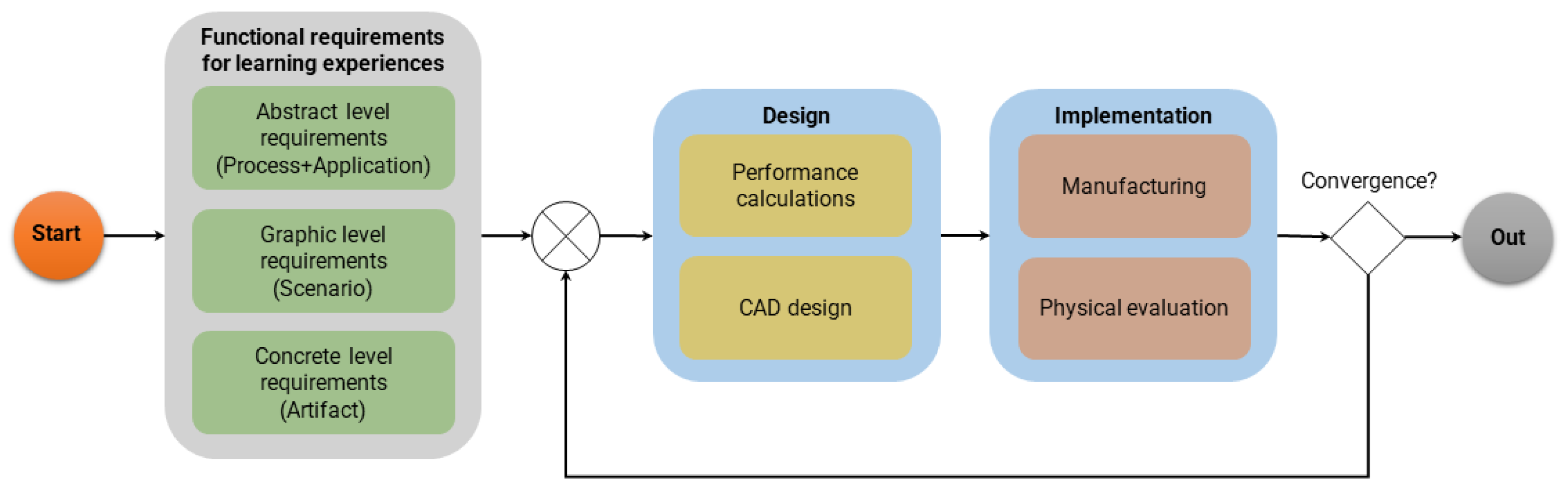
3.1. Functional Requirements for Learning Experiences
Functional requirements for learning experiences focus on the functionalities and features that the learning experience must have to meet its intended objectives effectively, i.e., specific and measurable criteria defining what the learning experience should be capable of doing or achieving. The process starts here, defining the requirements for the abstract, graphic, and concrete levels. The abstract level, focusing on learning outside of reality (the highest level of abstraction of the mechatronics core concepts), considers the process and application perspective. The graphic level, relating the elements of reality to graphics or symbolic elements, considers the scenario perspective. Finally, the concrete level, involving the manipulation of a real object, considers the artifact perspective.
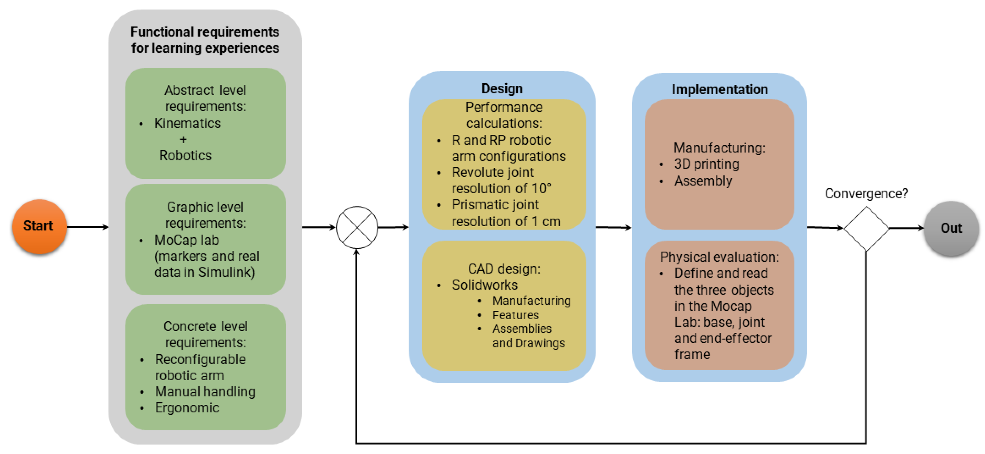
The chosen artifact or mechatronic prototype to be developed in this work is a serial robot manipulator. It has to include the necessary robot components (rotational joint, prismatic joint, links, base, and an end-effector) to illustrate a specific set of mechatronics core concepts such as translation, rotation, homogeneous transformation, and forward and inverse kinematics, among others. The aforementioned is part of the requirements of the abstract level. Moreover, the graphic level encompasses the use of the MoCap laboratory; therefore, the artifact has to consider the use of the MoCap markers and a system based on Simulink to obtain the linear and angular position of objects on the robotic arm. For the concrete level, the artifact has to be designed from a modular perspective. It has to be reconfigurable and ergonomic since it will be manipulated through hands-on activities (see
Figure 3).
3.2. Design of the Robotic Arm
The world of robots and their body models is entirely different. The first striking difference is that describing it is significantly more straightforward: robot body representations and control schemes are designed by engineers. They are thus very transparent, and unlike in the brain, we have complete access to all of the information. For the performance calculation, it is known that a 10° and 1 cm resolution is needed in the revolute and prismatic joint, respectively. Since the design of the revolute joint is inspired by a revolver cylinder, 36 positions equally spaced are considered, while the prismatic joint includes a simple graduate scale that shows the displacement by 1 cm at each mark.
The correct modeling methodology permits the selection of the proper order to create a CAD design in SolidWorks in order to obtain the best efficiency from our performance model, modeling changes, revisions, and the complementary items necessary for a file during its life cycle. Hence, several different items are considered before the creation of a model is begun [
24]:
Manufacturing: Defines how the part will be manufactured; then, the design considers only 3D printing and some aluminum parts to achieve a low-cost prototype.
Features: Defines those features of the model that will be the most efficient in working with it during the model’s development and life. Then, the model considers two scenarios: a traditional room and a MoCap system, so it has to consider the features needed for the user to interact with the robot manipulator kit in these scenarios.
Assemblies and Drawings: Defines how the parts are going to interact with the complete assembly. Then, the robot manipulator kit’s parts have to be designed independently and assembled in one file.
The results following the CAD modeling steps are depicted in
Figure 4,
Figure 5 and
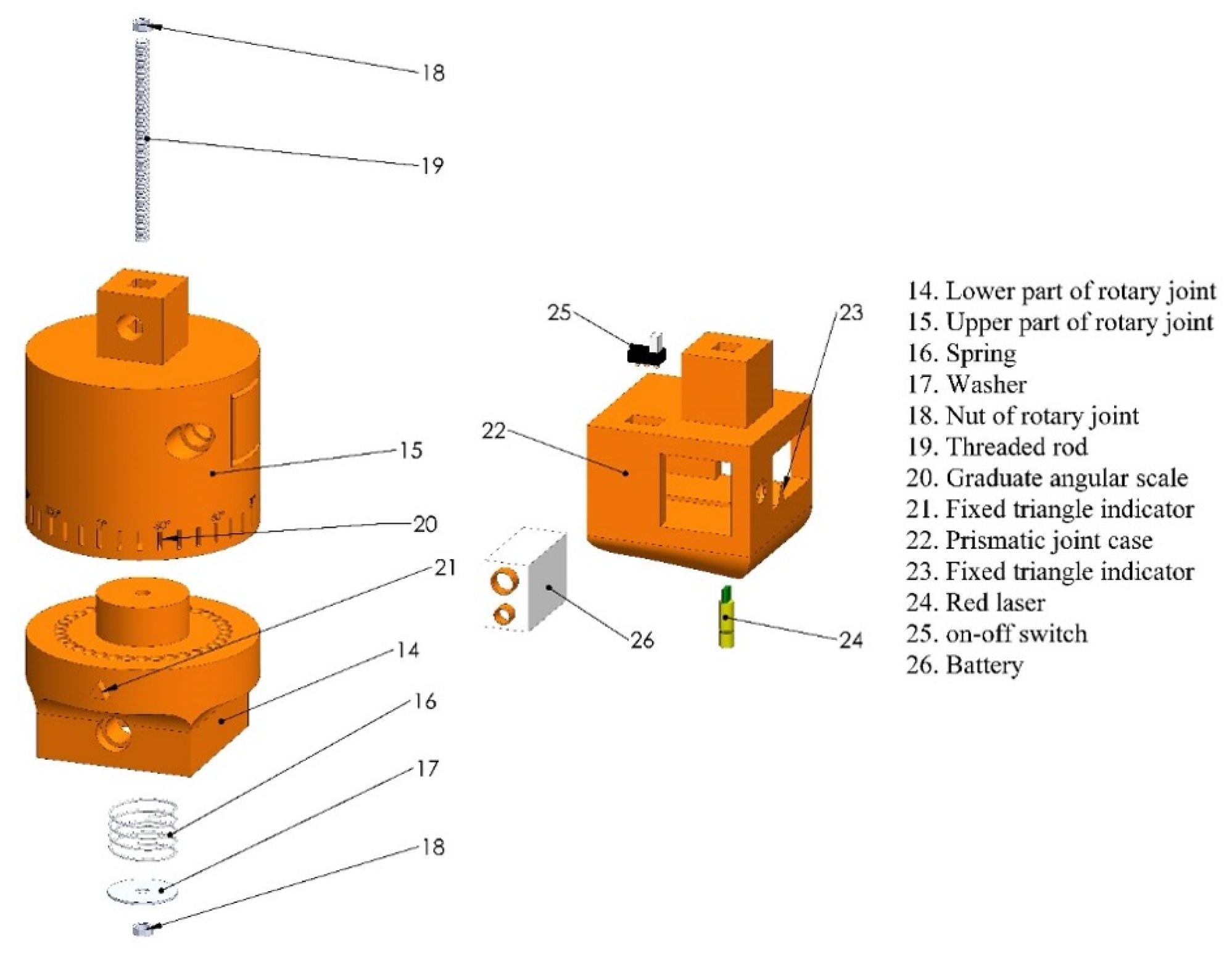
Figure 6. The exploded view of the robotic arm containing all its components is shown in
Figure 4. In contrast, the exploded view of the revolute and prismatic joint containing all their components is shown in
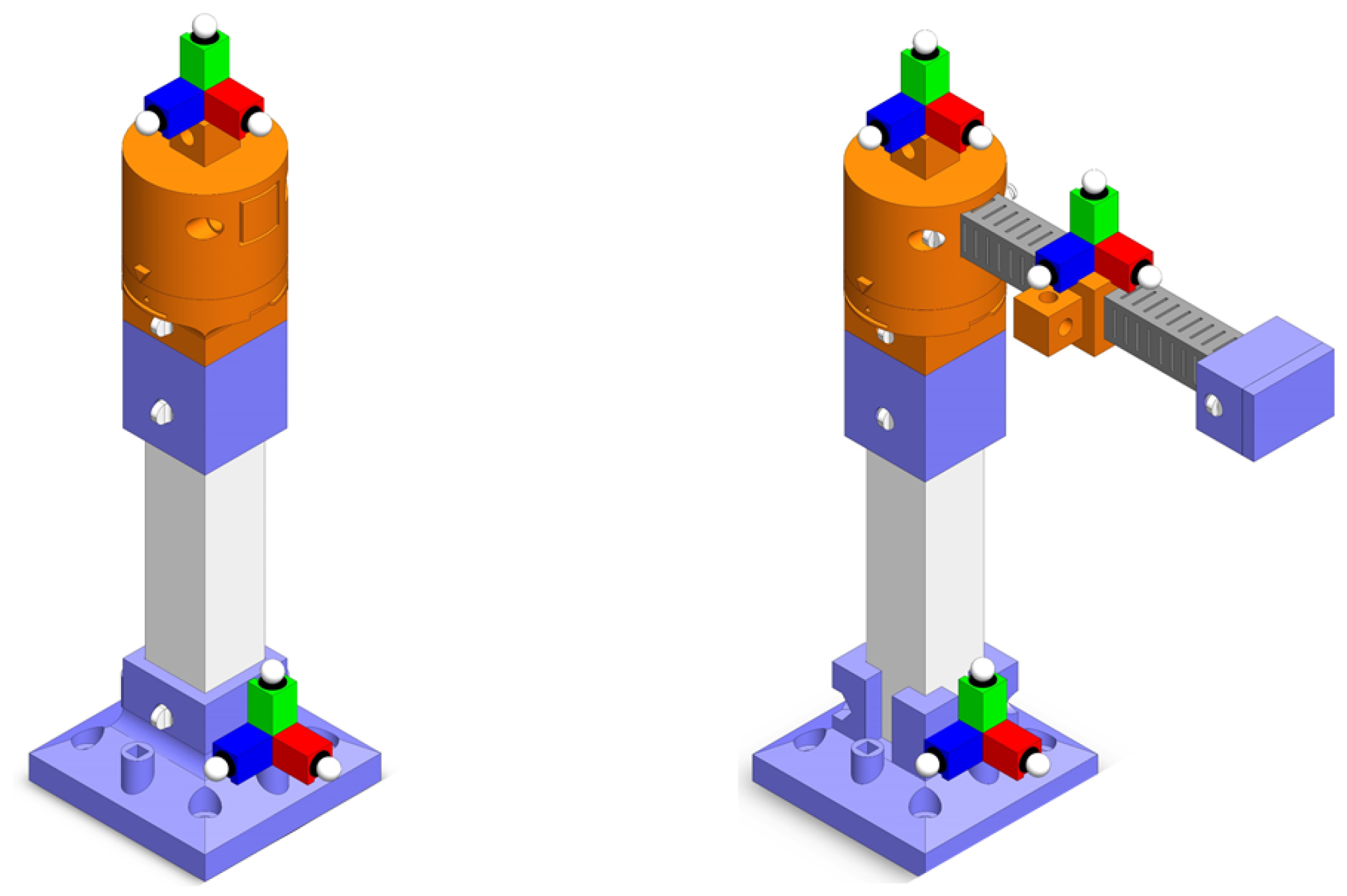
Figure 5. It is worthwhile mentioning that the design of the complete robotic arm is in the process of patent review, mainly for the design of the revolute joint. Finally,
Figure 6 depicts two different configurations: R, which corresponds to a 1 revolute joint configuration, and RP, which corresponds to a 2 degrees of freedom configuration with a revolute joint and a prismatic joint. These configurations were constructed in a sequence to build the knowledge of robot kinematics.
In general, the kinematic model of a serial manipulator is obtained through a sequence of 3D homogeneous transformations of the form
where
is the initial pose (position and orientation) of the end-effector of the serial manipulator,
is the transformation generated by the
joint of the manipulator and
corresponds to the value of the joint variable: an angle for a revolute joint and a distance for a prismatic joint.
is a
matrix obtained by means of the Denavit–Hartenberg parameters of the corresponding joint. Finally,
is the pose of the end-effector of the manipulator generated by the current value of the joint variables. For this work, a maximum of two joints are considered, but the proposed methodology can be applied for any number of joints.
3.3. Implementation of the Robotic Arm
As the developed kit is designed to be accessible, aluminum and plastic (polylactic acid plastic) with a 3D printer are the chosen construction materials for the manufacturing process.
After the design phase of all the pieces, the 3D printing process can start for most of the components of the robot manipulator. Specifically, components 1, 3, 4, 5, 6, 8, 12, 13, 14, 15, and 23 are entirely made from PLA plastic using a standard 3D printing process. In addition, aluminum is used in the base and graduate links particularly to manage the weight and stress that the complete model could generate during its normal functioning. According to
Figure 3, component 2 (base link) is a 2” aluminum square tube with two drilled 7/16” holes on each side. These holes are made to fix the base and the union point. Component 10 (graduate link) is a 1 ¼” aluminum square tube with two drilled 7/16” holes on each side of the tube; these holes are made so the rotary joint can be fixed with any joint of the manipulator robot. The joint arm also includes a graduate scale on each of the four sides that shows the displacement by 1 cm at each mark. The rotary joint has a rotational system that includes 36 positions to define a resolution of 10° and has a 1/8” × 3 ½” screw fully threaded, two pieces of a 1/8” nut, a 1/8” × 1 3/16” washer, and a 1 ½” long spring.
Finally, component 7 (MoCap marker) is a piece covered in a reflective light material intended for use in the MoCap system.
Figure 7 shows the designed versus the implemented robotic arm prototype.
Once the artifact is built, a physical evaluation has to be carried out. The MoCap laboratory is required to read the linear and angular position of the three objects on the robotic arm: the base, joint, and end-effector frame. In order to work with the MoCap system, a calibration must be performed first [
25,
26]. To do so, turn on the system and open the Vicon Tracker program. Then, select the “SYSTEM” tab and pick the eight cameras. Go to the “CALIBRATE” tab and click “START”. One person must take the active wand, turn it on with the solid red LEDs and go to the MoCap system workspace, and then start moving the wand in different directions with different orientations in front of each camera, as shown in
Figure 8.
After that, the Vicon Tracker software sends the results of the process calibration. If the results are not satisfactory, then the calibration process must be repeated until the results are correct. Then, the last step is to position the wand where the user wants to define as the origin of the workspace in the MoCap system of coordinates (see
Figure 9).
Next, the objects must be created to continue the setup to enable the robotic arm to work in the MoCap system. In this case, the robotic arm has three objects: the base frame (fixed-frame), the revolute joint frame, and the end-effector frame (see
Figure 10).
The last stage corresponds to the recollection of the measurements of the MoCap system by means of an application in Simulink, which is graphical programming IDE based on Matlab. Hence, the measurements are used to generate graphs of the position and orientation of each frame of the robotic manipulator, and a 3D graph of the absolute position of its end-effector. These graphs are displayed on a 50-inch TV monitor, which plays a fundamental role during the instructional design process based on the EEMCF. The first unit test of the robotic arm in the MoCap laboratory can be found at
https://youtu.be/dKEN0pFRg0E (accessed on 10 August 2023).
Then a convergence test is performed. If it is satisfactory, you must return to the sum point to recognize that entry requirements still need to be met and re-enter the design and implementation block as often as necessary. If the convergence is satisfactory, we are ready to leave the methodology for the design and implementation of educational tools to continue with the instructional design and thus build the learning experience.
4. Instructional Design for Mechatronic Concept: Robot Workspace
The robot manipulator kit is the correct tool to use when dealing with translation, rotation, the homogeneous transformation matrix, and forward and inverse kinematics, among other topics. This work considers the teaching case for which the instructional design is devoted to constructing the mechatronic concept of the workspace of a robot manipulator under the EEMCF, involving the perspective entities: kinematics (process) + robotics (application) + robot manipulator (artifact).
The pedagogical activities used to apply the learning construction methodology with the EEMCF are described in the following Subsections.
To start the practice, the instructor turns on the MoCap system, places the robot manipulator base matching the origin of the MoCap, and places the robot manipulator in its home position. Then, they start tracking the three objects: the base, revolute joint, and end-effector of the robot manipulator in Vicon Tracker, and open the Simulink to start plotting the 3D graph for the participant.
4.1. Concrete Learning Level
At this level, activities oriented to perceptual motor characteristics must be designed. We limit the robot arm’s range of movement from to for the rotary and prismatic joint fixed to 165 mm. The home position for the robot manipulator is and 165 mm. The set of instructions for participants are as follows (the instructor must start recording the position and orientation data):
- 1
Turn the robotic arm counterclockwise continuously from
to reach
and wait 1 min (see
Figure 11).
- 2
Turn the robotic arm counterclockwise continuously from to reach and wait 1 min.
- 3
Turn the robotic arm counterclockwise continuously from to reach and wait 1 min.
- 4
Turn the robotic arm counterclockwise continuously from to reach and wait 1 min; here, the home position is reached again. (Instruction remark: The instructor stops recording the data. The MoCap system records the position and orientation measurements of the three objects in an Excel table. This table will contain the set of points reachable by the manipulator’s end-effector, also called the robot’s workspace.)
4.2. Graphic Learning Level
At this level, activities must be designed that are oriented to the graphic (symbolic) representation of mechatronic concepts, taking as references the previously developed concepts at the concrete learning level, allowing the gradual transition from concrete to abstract. It is worth mentioning that non-dynamical images of the TV monitor are used. Moreover, the Excel file containing the recorded date is given to the participant. In addition, this level allows dynamic changes in the colors of the virtual images (such as circles or squares in a dynamic manner) but without allowing further movement of the robotic arm [
27].
Set of instructions for participants:
- 5
Observe and reflect on the 2D plot of the position and orientation of the robot base frame (see
Figure 12 and
Figure 13).
- 6
Observe and reflect on the 2D plot of the position and orientation of the revolute joint frame (see
Figure 14 and
Figure 15).
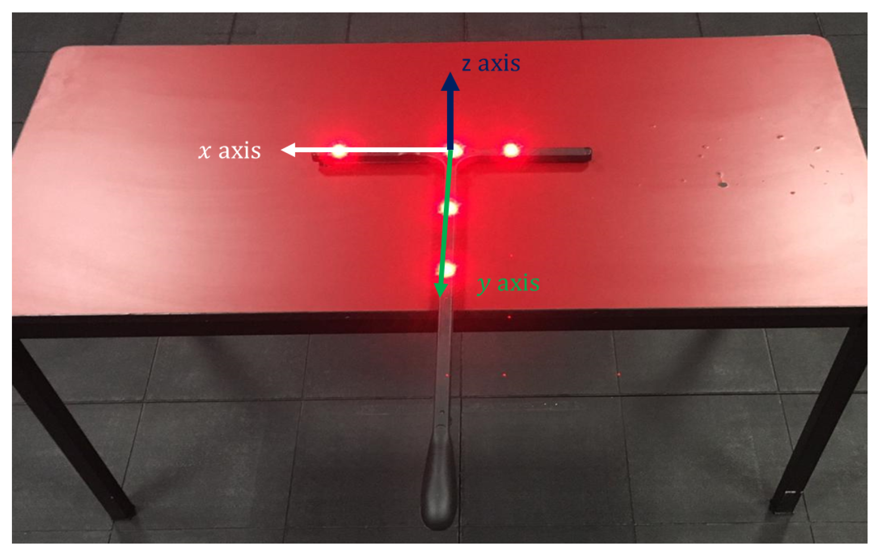
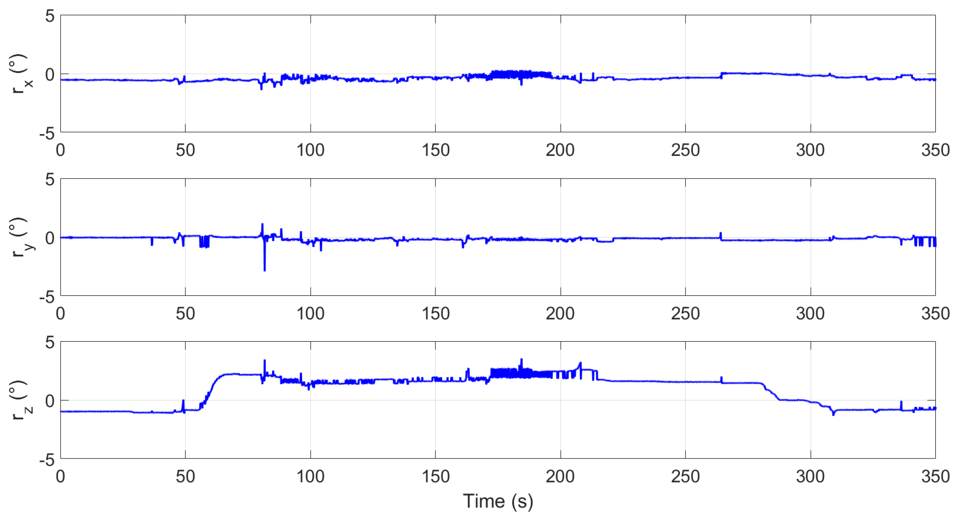
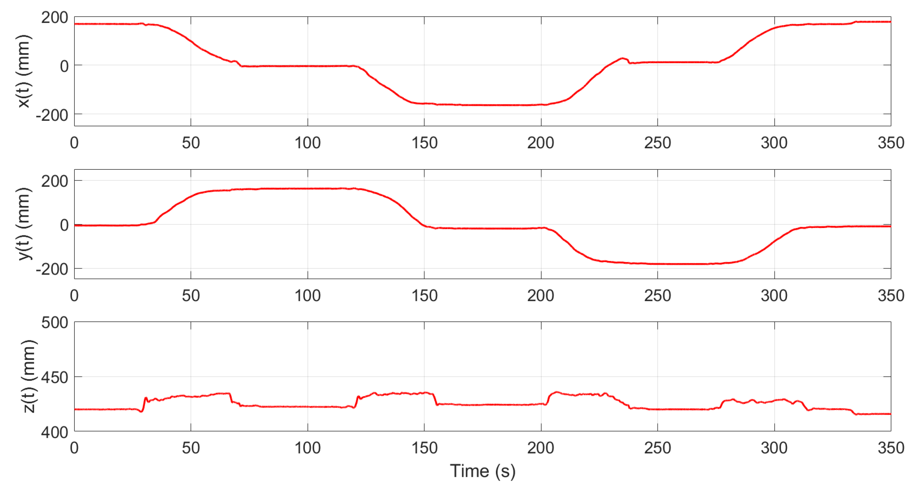
- 7
Observe and reflect on the 2D plot of the position and orientation of the end-effector frame (see
Figure 16 and
Figure 17).
- 8
Observe and reflect on the 3D plot of the three frames associated with the robotic arm (see
Figure 18 and
Figure 19). (Instruction remark: The instructor encourages the participants to link the points to the robot’s frames.)
4.3. Third Learning Construction Level
At this level, activities must be oriented to gradually transition from graphical concepts to a more abstract representation through symbolic or verbal representations, including digital text.
Set of instructions for participants:
- 9
Insert the text of the corresponding frame: base, revolute joint, and end-effector frame, in the image containing the top view of the 3D plot (see
Figure 20).
- 10
The end-effector frame includes the set of points reachable by the robotic arm, also called the workspace. It can be noted that the point cloud defines a circumference that is also the distance around the widest part of a round object or a line enclosing a circular space. Then, the equations describing the parametric form of a circle (connected line of points from
Section 4.2) are:
where
with
being the angle of rotation
,
r is the radius of the link of the robot that connects the revolute joint and the end-effector, and
is the center of the circle (real base of the robot, which is not the same as the robot base frame).
Figure 21 depicts the overlapping circle equation with the end-effector frame point cloud. Therefore, the participant can link the robot workspace with an equation of a circle centered in
. Moreover, the workspace is the total volume swept out by the end-effector as the manipulator executes all possible motions. It only includes the points in the circumference of the circle.
Instruction remark: the “x” and “y” values in the point cloud of the end-effector frame define the set of points reachable by the manipulator, also called the workspace.
It is essential to mention that the workspace is constrained by the manipulator’s geometry and the mechanical constraints on the joints. It is composed of the reachable and the dexterous workspaces. The former corresponds to the set of coordinates that can be reached by the manipulator, and the latter is the subset of the reachable workspace where the end-effector can have an arbitrary orientation [
28].
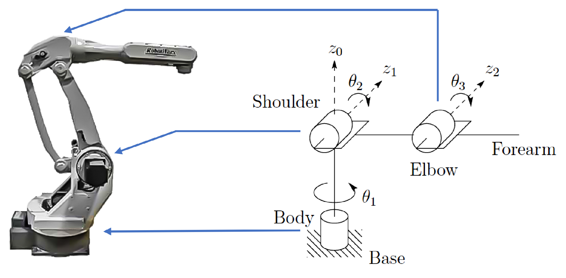
For example,
Figure 22 shows the Motoman SK16 manipulator and its structure, while
Figure 23 corresponds to its workspace. The mechatronic concept is: “The reachable workspace is the entire set of points where the manipulator’s end-effector can be positioned by modifying the values of its actuated joints”.
It is worth noting that from approximately
t = 310 s in
Figure 15 and
Figure 17, considerable uncertainty in the inertial orientation of the revolute joint frame and the end-effector frame, respectively, are depicted. These orientations, defined by the composition of three basic rotations in 3D, are computed by the API of the MoCap system utilized for the experiments [
26]. The algorithm used to calculate these angles requires knowing the position of at least four markers that define a frame and are detected by the MoCap system, as shown in
Figure 24.
Therefore, if a marker becomes occluded during an experiment, the algorithm cannot retrieve the angles that define the orientation of that specific frame, resulting in the phenomena indicated in
Figure 15 and
Figure 17. On the other hand, as the position of the origin of a frame can be retrieved using only three markers, the occlusion of one marker does not affect its computation, as shown in
Figure 14 and
Figure 16. Even though this is an undesirable consequence of the occlusion of markers during an experiment, it can be used to illustrate the geometric relationship between consecutive frames and the nature of the algorithms in the API of the MoCap system.
5. Discussion
The results obtained in this work are the educational tool design–implementation methodology, its application to generating the robotic arm aligned to the EEMCF, and the instructional development to build a mechatronics concept. To the best of our knowledge, no previous work connects the development process of instructional design with the generation of an educational tool. The tendency has been to generate or use robots and see how this process can fit into developing a learning experience.
In particular, the educational tool design–implementation methodology presented is intended to promote the generation of new, more significant, and natural learning experiences in the teaching–learning processes. For instance, several educative prototypes or learning systems such as in [
29] are commonly found in universities around the world. Nonetheless, the process of integrating these systems into an instructional design or developing a new one based on them is usually a challenging task.
The development of instructional designs involves the analysis of the specific content needs of the topic of the discipline, the definition of learning objectives, the selection of teaching strategies, the development of materials and resources where technological tools are created or selected, the design of evaluations, sequencing of content, the creation of interaction and participation with the incorporation of technology, continuous improvement, and implementation and evaluation.
Several pedagogies for engineering education have been proposed in the literature. However, if learning activities and objects are not structurally designed, pedagogical approaches might be ineffective in helping learners acquire and exhibit the skills necessary for their future industrial endeavors [
30]. With this in mind, it is essential to highlight the relevance of having the correct educational tool to drive learning activities. It delimits the learning objects with a set of mechatronics concepts that can be built. Moreover, this could bring a new perspective when designing educational tools for engineering education.
Finally, the following steps of this research project consider the construction of robotic prototypes with more complex configurations. This allows the teaching of more advanced mechatronics concepts such as dynamical modeling of several robotic manipulators. Furthermore, implementing the methodology with its corresponding robotic prototype will be a part of future work; this will enable the testing of the proposal with students in a real environment and permit the validation of the overall framework.
6. Conclusions
A modular robotic arm design aligned with the EEMCF using the design and implementation of educational tools methodology is presented, integrating a MoCap system as the learning scenario, robotics as the application, and robot kinematics concepts as the core element for the learning process. The aforementioned design is intended to prepare students in kinematics and give them the necessary knowledge for I4.0, particularly for applications of a real robot manipulator in the modern industry. Moreover, the developed instructional design allows learning to comply with the characteristics of mechatronic thinking, flexibility and attending to processes, applications, scenarios, and artifacts, holistically. The proposal allows the visualization of and interaction with elements and concepts in a three-level process: concrete, graphic, and abstract. It does not do so from a more reduced and specific concept such as educational robotics. In that regard, it is fundamental to increase the engagement of students at universities in educational mechatronics to improve the relevance of Mexico in the fourth industrial revolution.


 ,
, 


