Article

Parametric Modeling of Curvic Couplings and Analysis of the Effect of Coupling Geometry on Contact Stresses in High-Speed Rotation Applications

by
Chara Efstathiou
*,
Ioanna Tsormpatzoglou
and
Nikolaos Tapoglou
Department of Industrial Engineering & Management, International Hellenic University, Sindos Campus, 57400 Thessaloniki, Greece
*
Author to whom correspondence should be addressed.
Machines 2023, 11(8), 822; https://doi.org/10.3390/machines11080822
Submission received: 12 July 2023 / Revised: 7 August 2023 / Accepted: 8 August 2023 / Published: 10 August 2023
(This article belongs to the Special Issue High Performance and Hybrid Manufacturing Processes)

Abstract

:
Curvic couplings are used in applications demanding high positional accuracy and high torque transmission; therefore, improving their design and enhancing their load-carrying capacity is crucial. This study introduced the kinematic model Curvic3D, which was developed to produce the accurate geometry of both members of a curvic coupling using a CAD system. The model enabled the complete parametrization and customization of the coupling design using important geometric parameters. The couplings produced using Curvic3D were then imported into a finite element analysis model also developed as part of this study. A detailed analysis of the stresses developed on the teeth of the concave and convex parts provided information about the behavior of the coupling under different loading conditions. Finally, a series of geometric parameters, such as the number of teeth, the number of half pitches, the root fillet radius, and gable angle were examined as to their influence on the load-carrying capacity of the curvic coupling. The study concluded that all the examined parameters have a significant effect on the tooth flank and root area stresses.

1. Introduction

1.1. Curvic Coupling Applications

Curvic couplings are important components used in many industrial applications and especially in joining two shafts or two sections of a shaft. They are well-suited to applications demanding high precision, reliability, and high torque transmission capabilities. Curvic couplings are commonly used in the following sectors: 1. The aerospace industry, in jet engines, gas turbine power plants, and helicopter rotor systems. 2. Power generation, in gas and steam turbines, enabling the transmission of torque from the turbine to the generator. 3. Marine propulsion, in ship propulsion shafts and propellers. 4. Heavy machinery, such as mining equipment, industrial compressors and large-scale machine tools. 5. The defense industry, including military aircraft, armored vehicles and naval vessels. 6. The oil and gas industry, in oil and gas drilling and production machinery. They enable torque transmission in drilling rigs, pumps and compressors. 7. Robotics and automation, where precise motion control is necessary. They also find applications in robotic arms, CNC machines, and other automated equipment.

1.2. Curvic Coupling Geometry and Manufacturing

Curvic couplings are mechanical connections utilized for the connection of two rotating components and transmitting torque between them. They are designed to provide rigid connection, ensuring the accurate alignment of the shafts and high torque transmission. Additionally, a curvic coupling is advantageous in that its positional accuracy in both axes actually improves over time as opposed to degrading [1]. A curvic coupling is ring-shaped and consists of two members: the convex and the concave part. In most cases, the two members are clamped together with bolted connections. Both components have curved teeth placed circumferentially on the face of the part. This curvature is formed as a result of the machining process kinematics and tool geometry. Curvic couplings are most commonly machined with face-mill cutters or cup-type grinding wheels [2]. One member of the coupling is machined with the outer edge of the cutter, resulting in a concave tooth form, whereas the other member is machined with the inner edge of the cutter, forming a convex tooth, as shown in Figure 1. The kinematics of the process is relatively simple and is realized in the following steps. Firstly, the cutter engages with the left and right tooth flank feeding into the coupling until the final depth of the coupling slot is reached. The cutter is then retracted from the workpiece and remains at a certain distance until the workpiece rotates one pitch around its axis. Finally, the first step is repeated and the cutter is fed into the work gear at the next indexing position to machine the next slot of the coupling. This manufacturing process is a single-indexing process; thus, the slots are cut two at a time, and the manufacturing of a complete part of the curvic coupling is completed when all slots of the part are formed.
Figure 2 presents the basic geometry of the curvic coupling cutting tooth profile. The main geometric parameters affecting the geometry of the coupling teeth include the tooth addendum ha, tooth dedendum hd, normal pressure angle an, chamfer height hc, chamfer angle ac, gable angle ag, and tooth root radius rt.

2. State of the Art and Contribution of the Present Study

Research on curvic couplings and specifically curvic coupling manufacturing is relatively limited to the industrial sector. In their article, Gleason Works [2] provided fundamental knowledge on curvic couplings’ design. Τhe basic types of curvic couplings were listed, and brief descriptions of the respective manufacturing processes were provided. The authors also made useful suggestions for the geometry of fixed curvic couplings. The most important contribution of their work was the description of the complete design procedure to determine the necessary geometry of a curvic coupling to transmit a certain load. Richardson et al. [3] developed a three-dimensional and a two-dimensional finite element model for the simulation of the contact behavior of curvic couplings. The study aimed to compare the two simulation approaches and determine whether two-dimensional modeling is sufficient to analyze the contact of curvic couplings. A study to validate the three-dimensional finite element contact developed by Richardson et al. was presented in [4]. The finite element method results were evaluated in comparison with the results obtained from a photoelastic test. Rensis et al. [5] developed a three-dimensional axisymmetric curvic contact model to predict the maximum stresses in three loading cases. In his work on gas turbine engines, Boyce [1] described the role of couplings in power transmission between two shafts of an engine. Among others, the author discussed the use of curvic couplings in such setups. A three-dimensional finite element model was developed by Jiang et al. [6] to analyze the contact stresses of the curvic coupling in a gas turbine under a blade-off load condition. A methodology for the design of Hirth ring couplings which are used in the machine tool industry was provided by Croccolo et al. [7]. First, the standard formulas currently used in the industry were listed. Then, the forces generated in Hirth couplings were calculated with a new analytical method taking into account the role of friction. The proposed equations were also experimentally validated on a machine tool rotary table. Zhang et al. [8] presented a modified analytical method to calculate the equivalent stress on the double-row curvic coupling teeth, taking the deep beam bending effect into account. A finite element model was also presented to analyze the contact stress of the curvic couplings under different loads. The study concluded that the bolt preload has the greatest impact on the contact stress, while the rotating speed of the shaft reduces the contact stress. A new type of large curvic coupling gear consisting of a large gear and a curvic coupling was presented by Jung et al. [9]. Finite element analysis simulations were conducted to determine the maximum Von Mises stress developed on the model under two different external loads. Nielson [10] studied the potential of using CMM as a means of investigating the contact pattern of curvic couplings. In the field of the simulation of manufacturing processes, a series of studies have shown the potential of using CAD-based simulation models in complex manufacturing processes [11,12]. Li et al. [13] proposed a curvic coupling design with a double circular arc root fillet to improve the stress concentration on the tooth root. Huang et al. [14] proposed a method to calculate the machine setting parameters for curvic coupling manufacturing on a spiral bevel gear grinding machine. Pisani et al. [15] investigated the behavior of curvic couplings using two- and three-dimensional boundary finite element models. The two approaches were compared as to the required effort for the model generation, the results’ accuracy levels, and the post-processing capability. A method for the calculation of the contact and bending stiffness of a curvic coupling was developed by Yu et al. [16]. Kim et al. [17] presented a novel approach in curvic coupling modeling combining a Greenwood–Williamson contact model with a 3D solid element model. A study was also performed to investigate the effect of several parameters on vibration and stress. Yang et al. [18] investigated the stiffness of curvic couplings in order to determine the tensile–compressive stiffness of the coupling. In their investigation, they considered the stiffness characteristics of the coupling with uniform and non-uniform load distribution. A novel mechanical model considering the curvic coupling stiffness weakening in various loading conditions, such as shearing, compression, bending, and torsion, was developed by Liu et al. [19].
The present study introduces the first model for the kinematic simulation of curvic couplings’ manufacturing that accurately produces the convex and concave tooth geometry. Moreover, finite element analysis is utilized for the investigation of the effects of several geometric features of the two members on the load-carrying capacity of the coupling. A complete platform for the design, analysis of in-use performance, and manufacturing has been developed, allowing the end user to optimize the design and performance of curvic couplings.

3. CAD Model

Curvic3D is a CAD-based simulation model developed as part of this study. The algorithm simulates the process kinematics so the curvic tooth flank solid geometries are produced as output. This simulation approach aims to enable the accurate parametric modeling of curvic couplings. Figure 3 shows a flowchart of the simulation process. Modeling and simulation procedures are implemented in the following steps:
  • I: Calculation and modeling of the blank curvic coupling geometries.
The calculation process begins with the modeling of the two blank geometries for the convex and the concave component of the coupling. The blank geometries consist of two simple rings, the inner diameter of which is the inner diameter of the curvic coupling, while the outer diameter is the outer diameter of the curvic coupling. The area between the inner and outer diameter forms the face width of the curvic coupling tooth. As stated in [2], the inner diameter of the coupling should be equal to or greater than 75% of the outer diameter.
  • II: Tool profile and cutter geometry calculation.
Afterwards, the tooth profile geometry is calculated and drawn according to DIN 3972 standard [20]. The cutter radius and cutter center distance are calculated and considered in the modeling process.
  • III: Simulation of the process kinematics. Tool trajectory creation.
In order to obtain the solid geometry of the cutting tool, the process kinematics must be integrated with the tooth profile and cutter geometry. The kinematics of the process consists of a rotation of the cutter around its axis and feed of the cutter towards the workpiece. Parameters such as the cutter radius and cutter center distance are taken into consideration, and the solid geometry of the cutting tool is formed, as shown in the upper right part of Figure 3, as a result of the combination of process kinematics, tooth profile, and cutter geometry.
  • IV: Calculation of the convex and concave components’ geometry.
The final step of the simulation includes the interaction of the cutting tool and the two workpieces. Two subassemblies are formed; the first one consists of the cutting tool and the concave component, and the second one includes the cutting tool and the convex component. Using Boolean operations, such as Boolean subtraction, the simulated curvic tooth surface can be obtained. The algorithm is configured so that the final finishing pass of the machining operation is implemented; therefore, the cutting tool is placed directly at the final depth of the curvic slot. Nonetheless, the algorithm supports rough machining operation with the tool performing multiple passes until the final slot depth. This way, the undeformed chip geometries can also be obtained, enabling the calculation and analysis of the cutting forces.

4. Finite Element Analysis and Simulation Model

Aiming to achieve the analysis of the contact behavior and developed stresses of curvic couplings with variable geometries under various loading conditions, a finite element simulation model was developed. The solid models of the couplings were obtained using the CAD model Curvic3D. Three-dimensional modeling was preferred over two-dimensional as the complex geometry of a curvic coupling can be represented more accurately. The model aims to simulate the contact conditions and contact stresses for a curvic coupling in high-rotating speed applications such as high-pressure turbine shafts. The primary loads that couplings withstand in such applications are considered in the model, and all necessary assumptions are made, as described in the following paragraphs.

4.1. Solid Models and Materials

Figure 4 shows two indicative solid models of the two members of a curvic coupling used in the simulation. The assembled coupling is obtained from Curvic3D, and it can be used directly as is. A specific material has to be assigned to both members of the coupling. In the present investigation, AISI 4340 annealed steel was assigned to the curvic coupling throughout the study.
AISI 4340 is a nickel–chromium–molybdenum alloy steel, known for its toughness and strength, and it is used, among other applications, in gear manufacturing. Table 1 shows the specific material properties.

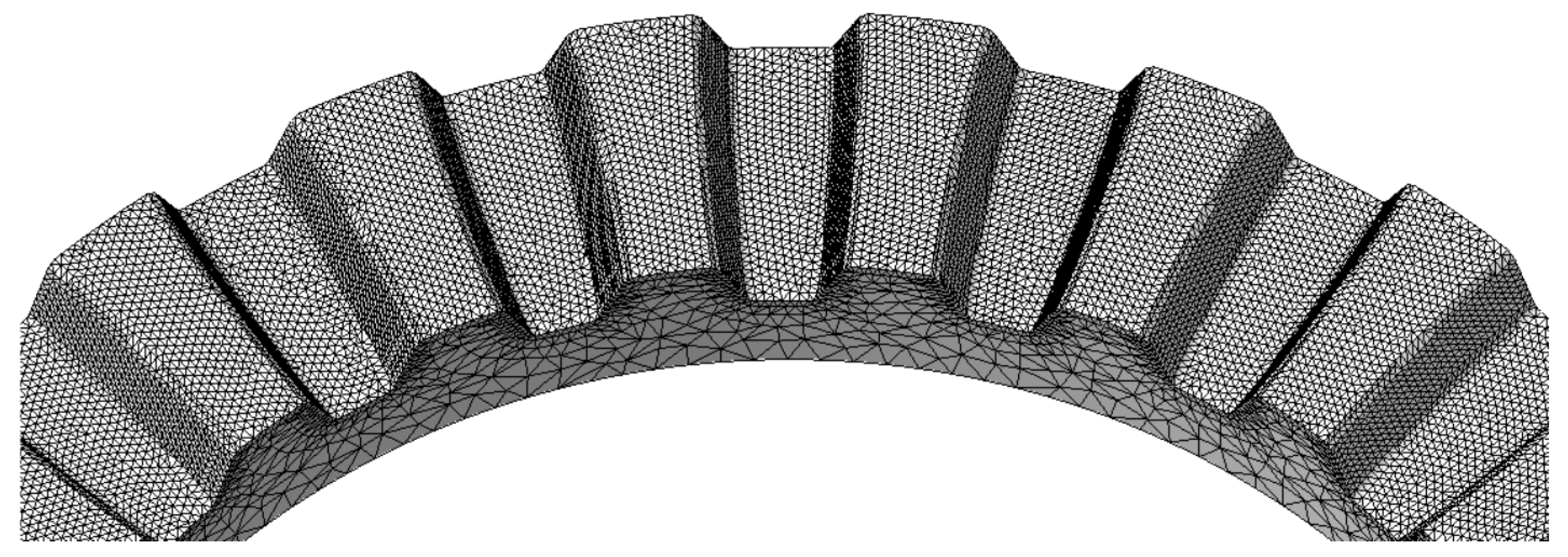
4.2. Global Mesh and Local Mesh Controls

The selected element type for both global and local mesh is the ten-node tetrahedral solid element. Two regions of mesh were assigned to both parts. The local mesh control with a 0.4 mm element size was applied to the coupling tooth surface to provide more accurate results since this was the region of interest. The global mesh applied to the rest of the solid bodies of both members in order to control the computational time had a 1.5 mm element size. Figure 5 shows the two types of mesh applied to each member.

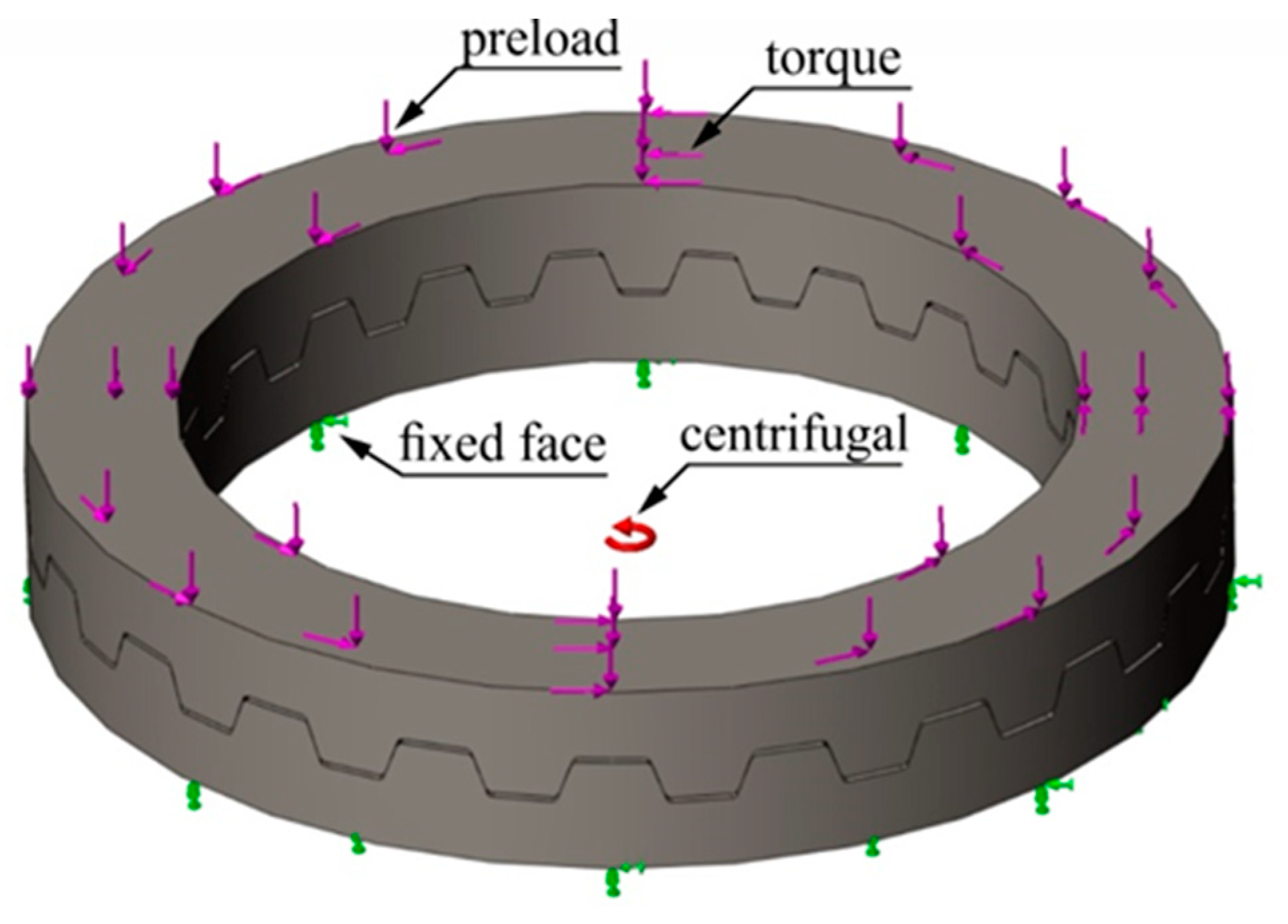
4.3. Boundary Conditions

Figure 6 presents the final boundary conditions of the model. The displacements and loads were defined based on the literature [8,9] as well as a series of simulations.

4.3.1. Loads

Centrifugal force: The centrifugal force applied on the curvic coupling results from the rotating speed of the shaft, which equals 10,000 rpm.
Torque: Equation (1) gives the separating force Fs acting on the curvic coupling as a result of the torque. Equation (2) provides the minimum clamping force Fc to counterbalance the action of separating force Fs. Equations (3) and (4) provide the stresses σt and σc developed due to the act of clamping force and torque. The allowable torque is calculated according to Equation (5), which gives the equivalent stress on the coupling teeth caused when the coupling is subjected to the bolt preload (clamping force) Fc and the torque T.
F s = T A × tan a n
F c = 1.5 × T A × tan a n
σ t = T A × Z × w × h 0
σ c = F c 2 × Z × w × h 0 × tan   a n
σ eq = F c 2 × Z × w × h 0 × tan   a n + T A × Z × w × h 0
According to Equation (5), setting the maximum allowable stress on the teeth at σa = σy/sf = 156.7 MPa with the safety factor at sf = 3, the maximum allowable torque value is calculated to be T = 4642 N·m. This torque is applied to the model for all the simulations performed in this study.
Clamping force: To define the displacement boundary conditions of the convex gear, a series of simulations was conducted to determine the necessary preload force to compensate for all the separating forces acting on the curvic coupling. The minimum preload clamping force to prevent the separation of the two members should exceed the sum of all the separating forces acting on the coupling. According to Gleason Works [2], the clamping force should be at least 1.5–2 times the sum of all separating forces acting on the curvic coupling teeth. In this study, several simulations were performed to determine the necessary clamping force so the curvic coupling was not disassembled. For a given centrifugal force resulting from the rotational speed N = 10,000 rpm and torque T = 4642 N·m, the minimum clamping force was defined as Fc = 42 kN. Applying this clamping force to the coupling, the distance between the two members during simulation was not increased by more than 15 μm.

4.3.2. Displacements

As shown in Figure 6, the axial and angular displacements at the back face of the concave member are constrained to 0 (fixed face), a necessary assumption made to avoid the excessive displacement of the model and prevent the simulation from failing. In operating conditions, the displacements’ constraints would be shared between the convex and the concave part. The displacements of the convex member are only controlled via the clamping force and are not subject to any other constraints. Furthermore, an investigation to determine the suitable displacement boundary conditions was carried out, examining the behavior of the model under different displacements’ constraints. The above described displacements were selected because they better represent the actual curvic coupling operation and have also been used by other researchers in the literature [8,9].

4.4. Interaction Conditions

The no-penetration contact condition was applied globally to the model. Under this contact condition, the two parts/models of the curvic assembly behave as two separate solid bodies that interact but cannot penetrate each other. The friction coefficient between the two parts was set to μ = 0.15.

4.5. Results

An analysis of the coupling behavior under different loading conditions was carried out prior to determining the final loading state that would be applied on the curvic coupling. Two loading cases were examined: 1. assembly, where only the clamping force is applied to the model, and 2. operation, where preload force, centrifugal force, and torque are loading the coupling as in normal operation. The results showed that loading the curvic coupling with only the clamping force was the most demanding case with respect to the developed stresses as the maximum Von Mises stress reached σv,max = 469 ΜPa, which is practically the yield strength of the material. In the second loading case of operation where the coupling was subjected to all three loads, the maximum Von Mises stress did not exceed σv,max = 357 MPa.
A baseline finite element simulation was performed using the boundary conditions presented above and was used as a reference for the subsequent parameters investigation. The solid model of the curvic coupling was obtained from Curvic3D, and the geometric features of the coupling are shown in Figure 7. As can be seen in the figure, the stresses are distributed evenly on the loaded tooth surface of both concave and convex members. The maximum Von Mises stress occurred along the tooth root of the convex gear. While the opposite tooth surface was not loaded, the opposite root area carried some load but the stress remained at low levels.
Since the maximum Von Mises stress of σv,max = 357 MPa is lower than the yield strength of the material (σy = 470 MPa) and the minimum factor of safety is FOS = 1.316, the results were reasonable and could be used as a reference for the subsequent investigation. Figure 8 presents the factor of safety plot for the convex member of the coupling. As can be observed, the stresses developed for the most part of the curvic correspond to an FOS = 3, except for a narrow region at the root of the loaded flank of the tooth where the safety factor drops at lower values. These results verify the calculation procedure using Equations (1)–(5), considering that these equations are only used as an approximation of the actual loading conditions; hence, many assumptions and simplifications are made.
Figure 9 shows the displacement plot of the curvic coupling. As mentioned above, the displacements of the back face of the concave part are constrained to 0, and this is also noticeable in the figure. The maximum displacements are observed on the convex member and stay below 12 μm due to the adjustment at the clamping load, which was determined in order to counterbalance the separating forces acting on the coupling.

5. Investigation of the Effect of Geometric Parameters on the Contact Stresses

Following the development of the FEA simulation model and the initial assessment of the simulation results, a series of simulations was carried out to investigate the effect of several coupling geometric parameters on the developed Von Mises stresses. For each simulation case, a separate curvic coupling was modeled using Curvic3D and was subsequently embedded in the finite element model.

5.1. Effect of the Number of Teeth

For the examination of the effect of the number of teeth, three simulation cases with varying numbers of teeth—Z = 21, 24 and 27—showed that the maximum developed Von Mises stress decreases from σv,max = 394 MPa to σv,max = 330 MPa as the number of teeth increases. Figure 10 shows the values of maximum Von Mises stress obtained from the three simulation cases. All of the maximum stress values were developed at the tooth root of the convex gear. The dramatic effect of the number of teeth on the Von Mises stress is explained by the fact that as the number of teeth increases, the load is distributed amongst more teeth, leading to a decrease in overall stresses.

5.2. Effect of the Number of Half Pitches

The number of half pitches included between the two tooth flanks that the cutter machines is also an important parameter affecting the geometry and therefore the strength of the curvic couplings. As shown in Figure 11, the increase in half pitches decreases the maximum developed Von Mises stress from σv,max = 363 MPa to σv,max = 319 MPa. This can be explained due to the fact that the maximum stress in all simulation cases develops at the convex gear tooth root, the tooth thickness of which increases with the increase in half pitches.

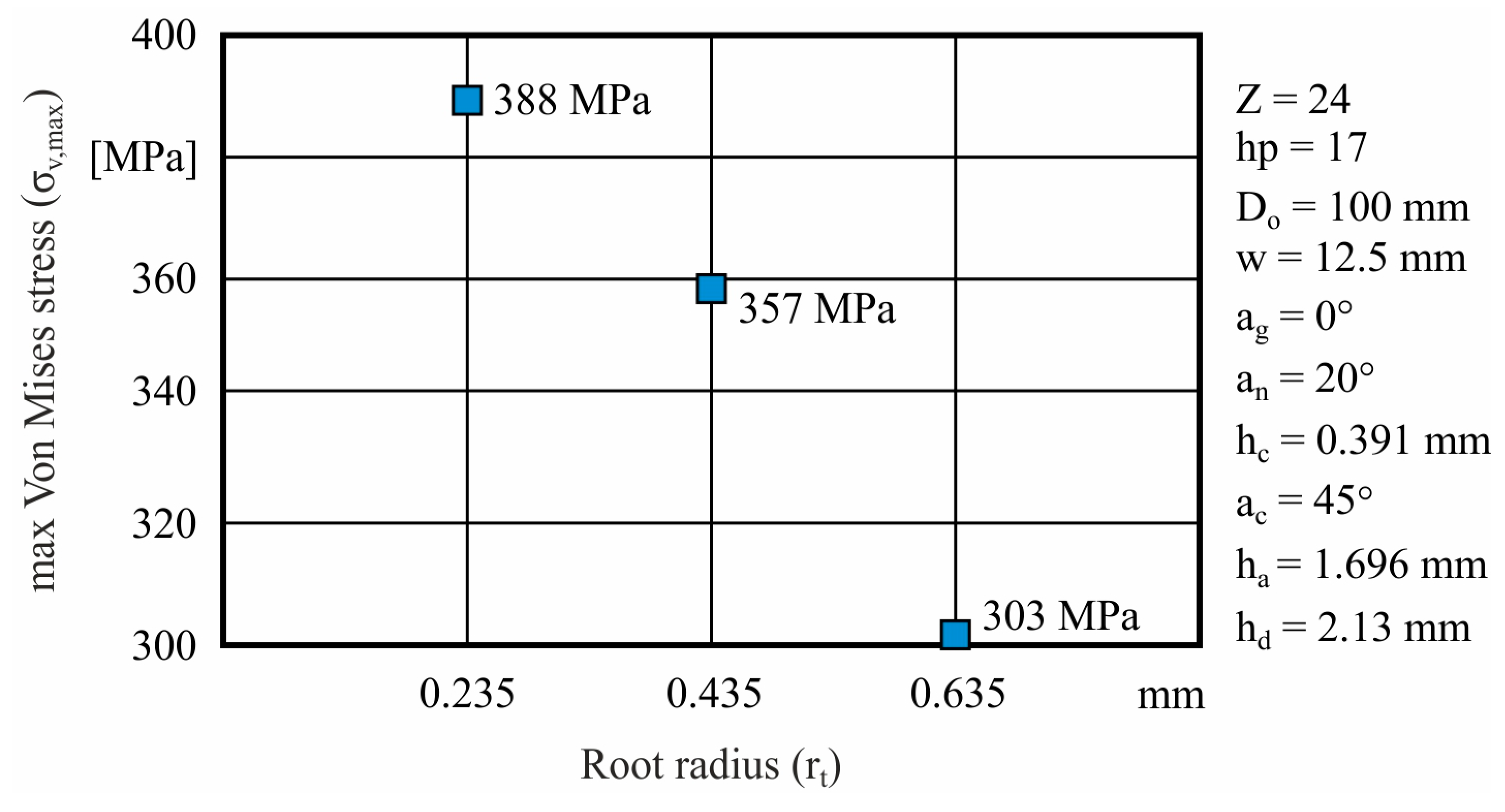
5.3. Effect of Tooth Root Radius

Analyzing the effect of tooth root radius on the development of Von Mises stresses, three cases were examined in which the tooth radius was rt = 0.235, 0.435, and 0.635 mm. In all three cases, the maximum stress occurred on the root of the convex member; therefore, the change in root radius had a great impact on the maximum Von Mises stress which dropped from σv,max = 388 MPa to σv,max = 303 MPa, as shown in Figure 12. The increase in the root radius enhanced the strength of the coupling; thereby, the maximum stress decreased dramatically.

5.4. Effect of the Gable Angle

A useful parameter that many curvic coupling manufacturers take into consideration is the gable angle. A total of seven simulations were executed to determine the effect of gable angle on the development of Von Mises stress on the coupling. The results revealed an interesting relation between the increase in gable angle and maximum Von Mises equivalent stress. As can be seen in Figure 13, the maximum Von Mises stress remains constant at about 360 MPa from ag = 0° until the gable angle reaches 1.5° and then slightly increases to reach σv,max = 376 MPa at ag = 3.5°. At ag = 4°, the maximum Von Mises stress value drops abruptly close to σv,max = 305 MPa and remains constant for the rest of the simulation cases. Hence, it can be concluded that, for this particular curvic coupling geometry, values of the gable angle between ag = 4° and 5° are optimum as they would result in reduced stresses. Values of the gable angle above 5° were not examined since the produced geometry would not lead to an allowable assembly.

6. Conclusions

The CAD model Curvic3D for the parametric three-dimensional modeling of curvic couplings was developed as part of this study. The model simulates the manufacturing process kinematics achieving the automatic modeling of the solid geometries of both convex and concave members of the coupling, using custom-defined parameters. A finite element analysis was also carried out to study the stresses developed on the tooth contact surface during operation at high rotating speed. Several case studies were simulated to investigate the influence of different geometric parameters on the developed Von Mises stress. The solid geometries of the curvic couplings were obtained from Curvic3D and examined with FEA for their load-carrying capacity. The number of teeth, the number of half pitches, the tooth root radius, and the gable angle were analyzed as to their effect on the load-carrying capacity of the curvic coupling. All of these parameters were found to have a great impact on the strength of the coupling, and the results were discussed in detail. The tooth root radius had the strongest impact on the developed stresses, followed by the number of teeth and the gable angle. All of the parameters showed a standard trend of the maximum Von Mises stress except for the gable angle. More specifically, the maximum stress decreased with the increase in the number of teeth, the increase in the root radius, and the increase in half pitches. On the contrary, maximum stress slightly increased with the increase in the gable angle before dropping abruptly above ag = 3.5°.

Author Contributions

Conceptualization, Ν.T. and C.E.; methodology, Ν.T. and C.E.; software, N.T., C.E. and I.T.; validation, C.E. and N.T.; investigation, C.E. and I.T.; writing—original draft preparation, C.E.; writing—review and editing, C.E. and N.T.; supervision, N.T. All authors have read and agreed to the published version of the manuscript.

Funding

This research received no external funding.

Data Availability Statement

The data presented in this study are available on request from the corresponding author.

Conflicts of Interest

The authors declare no conflict of interest.

Nomenclature

DiInner curvic diametermm
DoOuter curvic diametermm
ZNumber of teeth-
hpNumber of half pitches-
wFace widthmm
RwGrinding wheel radiusmm
haTooth addendummm
hdTooth dedendummm
anNormal pressure angle°
acChafmer angle°
hcChafmer heightmm
agGable angle°
rtTooth root radiusmm
FsSeparating forceN
TTorqueN·mm
AMean radius of the couplingmm
FcClamping forceN
σtStress due to torqueMPa
h0Contact heightmm
σcStress due to clamping forceMPa
σeqEquivalent stressMPa
σv,maxMaximum Von Mises stressMPa
σyYield strengthMPa

References

  1. Boyce, M.P. (Ed.) 18—Couplings and Alignment. In Gas Turbine Engineering Handbook, 4th ed.; Butterworth-Heinemann: Oxford, UK, 2012; pp. 693–719. [Google Scholar] [CrossRef]
  2. Gleason Works. Curvic Coupling Design. Gear Technol. November/December 1986, 34–48. Available online: https://www.geartechnology.com/ext/resources/issues/1186x/Back-to-Basics.pdf (accessed on 11 July 2023).
  3. Richardson, I.J.; Hyde, T.H.; Becker, A.A.; Taylor, J.W. A comparison of two and three dimensional finite element contact analysis of Curvic couplings. Trans. Eng. Sci. 1999, 24, 11. [Google Scholar]
  4. Richardson, I.; Hyde, T.; Becker, A.A.; Taylor, J. A validation of the three-dimensional finite element contact method for use with Curvic couplings. Proc. Inst. Mech. Eng. Part G J. Aerosp. Eng. 2002, 216, 63–75. [Google Scholar] [CrossRef]
  5. Rencis, J.J.; Pisani, S.R. Using three-dimensional CURVIC® contact models to predict stress concentration effects in an axisymmetric model. WIT Trans. Model. Simul. 2005, 39, 10. [Google Scholar]
  6. Jiang, X.-J.; Zhang, Y.-Y.; Yuan, S.-X. Analysis of the contact stresses in curvic couplings of gas turbine in a blade-off event. Strength Mater. 2012, 44, 539–550. [Google Scholar] [CrossRef]
  7. Croccolo, D.; Agostinis, M.; Fini, S.; Olmi, G.; Robusto, F.; Vincenzi, N. On Hirth Ring Couplings: Design Principles Including the Effect of Friction. Actuators 2018, 7, 79. [Google Scholar] [CrossRef] [Green Version]
  8. Zhang, D.; Yang, C.; He, T.; Liu, J.; Hong, J. Modelling and stress analysis for double-row curvic couplings. Proc. Inst. Mech. Eng. Part C J. Mech. Eng. Sci. 2020, 235, 4231–4243. [Google Scholar] [CrossRef]
  9. Jung, Y.-S.; Gao, J.-C.; Lee, G.-I.; Jung, K.-R.; Kim, J.-Y. Large Curvic Coupling Gear for Ultraprecision Angle Division Using FEM. Int. J. Precis. Eng. Manuf. 2021, 22, 495–503. [Google Scholar] [CrossRef]
  10. Nielson, B.J. Digital Inspection of Fixed Curvic Coupling Contact Pattern. Master’s Thesis, Faculty of California Polytechnic State University, San Luis Obispo, CA, USA, 2012. [Google Scholar]
  11. Efstathiou, C.; Tapoglou, N. Simulation of spiral bevel gear manufacturing by face hobbing and prediction of the cutting forces using a novel CAD-based model. Int. J. Adv. Manuf. Technol. 2022, 122, 3789–3813. [Google Scholar] [CrossRef]
  12. Tapoglou, N. Calculation of non-deformed chip and gear geometry in power skiving using a CAD-based simulation. Int. J. Adv. Manuf. Technol. 2019, 100, 1779–1785. [Google Scholar] [CrossRef] [Green Version]
  13. Li, A.-M.; Cui, H.-T.; Wen, W.-D.; Huang, F. Design and optimization of curvic coupling with double circular-arc root fillet in aero-engine. J. Propuls. Technol. 2016, 37, 146–155. [Google Scholar]
  14. Huang, D.; Wang, Z.; Zeng, T. Manufacturing method for fixed curvic coupling. China Mech. Eng. 2013, 24, 1877–1880+1885. [Google Scholar]
  15. Pisani, S.R.; Rencis, J.J. Investigating CURVIC coupling behavior by utilizing two- and three-dimensional boundary and finite element methods. Eng. Anal. Bound. Elem. 2000, 24, 271–275. [Google Scholar] [CrossRef]
  16. Yu, Y.; Lee, B.; Cho, Y. Analysis of contact and bending stiffness for Curvic couplings considering contact angle and surface roughness. Proc. Inst. Mech. Eng. Part E J. Process Mech. Eng. 2019, 233, 1257–1267. [Google Scholar] [CrossRef]
  17. Kim, B.J.; Oh, J.; Palazzolo, A. An improved preloaded Curvic coupling model for rotordynamic analyses. J. Sound. Vib. 2023, 544, 117391. [Google Scholar] [CrossRef]
  18. Yang, C.; Zhang, D.; Dou, Y.; Hong, J. Stiffness Modelling for One Curvic Coupling Considering Contact Details. In Proceedings of the 14th International Conference on Vibration Problems, Crete, Greece, 1–4 September 2019; Sapountzakis, E.J., Banerjee, M., Biswas, P., Inan, E., Eds.; Springer Nature Singapore: Singapore, 2021; pp. 593–613. [Google Scholar]
  19. Liu, H.; Hong, J.; Ruan, S.; Li, Z.; Cheng, G. A Model accounting for Stiffness Weakening of Curvic Couplings under Various Loading Conditions. Math. Probl. Eng. 2020, 2020, 1042375. [Google Scholar] [CrossRef] [Green Version]
  20. DIN3972; Bezugsprofile von Verzahnwerkzeugen für Evolventenverzahnung nach DIN 867. Köln Beuth: Berlin, Germany, 1952.
Figure 1. Curvic coupling manufacturing principle.
Machines 11 00822 g001
Figure 2. Curvic coupling cutting tooth profile.
Machines 11 00822 g002
Figure 3. CAD-based simulation model flowchart.
Machines 11 00822 g003
Figure 4. Curvic coupling solid models.
Machines 11 00822 g004
Figure 5. Global mesh and tooth surface mesh control on the concave part.
Machines 11 00822 g005
Figure 6. Finite element model boundary conditions.
Machines 11 00822 g006
Figure 7. Von Mises stress plot.
Machines 11 00822 g007
Figure 8. Factor of safety plot.
Machines 11 00822 g008
Figure 9. Displacement plot.
Machines 11 00822 g009
Figure 10. Effect of the number of teeth (Z) on the developed Von Mises stress.
Machines 11 00822 g010
Figure 11. Effect of the number of half pitches (hp) on the developed Von Mises stress.
Machines 11 00822 g011
Figure 12. Effect of the tooth root radius (rt) on the developed Von Mises stress.
Machines 11 00822 g012
Figure 13. Effect of the gable angle (ag) on the developed Von Mises stress.
Machines 11 00822 g013
Table 1. Material properties of AISI 4340 annealed steel.
PropertyValueUnits
Density7850kg/m3
Elastic modulus205GPa
Yield strength470MPa
Specific heat475J/Kg·K
Disclaimer/Publisher’s Note: The statements, opinions and data contained in all publications are solely those of the individual author(s) and contributor(s) and not of MDPI and/or the editor(s). MDPI and/or the editor(s) disclaim responsibility for any injury to people or property resulting from any ideas, methods, instructions or products referred to in the content.

