Article

Design and Analysis of a Supine Ankle Rehabilitation Robot for Early Stroke Recovery

1
College of Medical Instruments, Shanghai University of Medicine and Health Sciences, Shanghai 201318, China
2
Institute of Rehabilitation Engineering and Technology, University of Shanghai for Science and Technology, Shanghai 200093, China
3
Shanghai Engineering Research Center of Assistive Devices, Shanghai 200093, China
*
Author to whom correspondence should be addressed.
Machines 2023, 11(8), 787; https://doi.org/10.3390/machines11080787
Submission received: 21 June 2023 / Revised: 26 July 2023 / Accepted: 28 July 2023 / Published: 31 July 2023
(This article belongs to the Special Issue Recent Advances in Medical Robotics)

Abstract

:
Existing ankle rehabilitation robots are large, difficult to move, and mostly designed for seated use, which cannot meet the early bedridden rehabilitation goals of stroke patients. To address these issues, a supine ankle rehabilitation robot (S-ARR) specifically designed for early bedridden rehabilitation of stroke patients has been proposed. The S-ARR is designed to be easily movable and adaptable to different heights. It features a variable workspace with mechanical limiters at the rotating joints. A kinematic model has been constructed, and the kinematic simulation of the S-ARR has been analyzed. A control system scheme for the S-ARR has been proposed. Additionally, experiments have been conducted on the prototype to measure joint range of motion and perform rehabilitation exercises. The simulation and experimental results demonstrate that the S-ARR has a feasible workspace and a relatively smooth motion process, enabling it to achieve supine ankle rehabilitation training. This indicates that the design of the supine ankle rehabilitation robot is reasonable, capable of meeting the requirements for ankle joint rehabilitation training, and has practical utility.

1. Introduction

Stroke is an acute cerebrovascular disease which is caused by the sudden rupture of cerebral blood vessels or the blockage of blood flow to the brain, resulting in damage to brain tissues. It includes ischemic and hemorrhagic stroke. It is characterized by a high incidence rate, high mortality rate, high disability rate, and various complications, especially the tendency to cause hemiplegia and mild hemiplegia [1,2]. For stroke patients, the ankle joint plays an important role in daily activities, and severe ankle joint contracture caused by stroke greatly limits the mobility of stroke survivors [3,4]. Existing medical theories and clinical experiments have shown that effective rehabilitation training can prevent muscle atrophy and promote ankle joint recovery. Early intervention in rehabilitation training contributes to the restoration of human motor function [5].
Ankle joint rehabilitation plays a crucial role in the gait performance and daily activity recovery of stroke patients [6]. Traditional rehabilitation training usually requires one-on-one or group consultations, which are inefficient, labor-intensive, and lack scientific and effective data monitoring and feedback. Robot-assisted therapy has been proposed as a method to address these issues [7]. With the deep integration of rehabilitation medicine and robotics, various models of ankle joint rehabilitation robots have been designed. Typically, ankle joint rehabilitation robots can be divided into two types: wearable and platform-based [8,9]. Zhang et al. [10] designed a parallel ankle rehabilitation robot with three rotational degrees of freedom, driven by stepper motors. They also constructed a complete information acquisition system to improve human–machine interaction between the robot, patients, and doctors. Amir Bahador Farjadian et al. [11] designed a virtual interface ankle balance training robot (vi-RABT), which is a platform-based robot used for ankle joint and balance rehabilitation. Minh Duc Dao et al. [7] developed an ankle joint rehabilitation device for stroke patients with a simple and compact structure, convenient for patients to wear and improve rehabilitation effectiveness. Cio et al. [12] proposed a novel Rutgers Ankle CP robot, allowing young people with cerebral palsy to use it. After 36 rehabilitation treatments, the patient’s function and quality of life improved, attributed to the increase in ankle joint strength and control ability. Currently, mature products on the market include European/Smart Wearable, which applies to both the left and right feet, guided by games, and capable of active and passive training modes. Other similar products include Ankle Motus™ developed by the Shanghai Fourier Intelligent Technology Company (Shanghai, China). However, the above rehabilitation devices are bulky and expensive, suitable only for use in hospitals or treatment centers, and not applicable for home use, posing difficulties for stroke patients during the early bedridden stage. To address this drawback, the Dalian University of Technology (Dalian, China) [13] designed a two-degree-of-freedom serial ankle joint rehabilitation trainer suitable for bedridden patients and developed various modes, such as circular trajectory, transverse serpentine trajectory, longitudinal serpentine trajectory, and abduction-type elliptical trajectory, providing references for developing specific muscle group training modes. Kocaeli University (Izmit, Turkey) created a low-cost portable wrist rehabilitation robot (POWROBOT) that can be used at home as well as in physical therapy centers [14]. The University of Calabria designed a novel bionic robotic device for upper limb rehabilitation tasks at home, which is easily portable and remotely managed by professional therapists [15]. The mobility of the above rehabilitation devices ensures the continuity of rehabilitation exercises, which is essential in the patient’s rehabilitation process. Lightweight and portable design are also important aspects in the development of rehabilitation devices. Meanwhile, some ankle joint rehabilitation robots designed for specific populations have been developed. Kevin Cleary and his team [16] developed an Active Compliant End-Effector (ACE), which is a six-degree-of-freedom fully rotational joint device used for ankle exercises in children with cerebral palsy. Furthermore, Kevin Cleary’s research group developed two versions of an ankle joint robot [17] for cerebral palsy children: one for home therapy and one for laboratory treatment. These devices are connected to games, stimulating the children’s willingness for rehabilitation therapy. Additionally, some ankle joint rehabilitation robots have been developed to accommodate different usage postures. Fang Ming Lim and others [18] developed a supine gait training device aimed at early central nervous system rehabilitation for patients. However, its design lacks adjustability, limiting its applicability to specific user groups. Jianfeng Li and colleagues [19] created a novel reconfigurable muscle strength training robot to increase users’ muscle strength and endurance. Nonetheless, the large size and expensive price of this device restricts its usage in hospitals or rehabilitation training institutions. On the other hand, an emerging trend is the use of flexible actuators and materials to develop rehabilitation devices, which can provide patients with more compliance, safety, and comfort, avoiding secondary injuries caused by rigid structures. Flexible actuators are usually made of flexible materials such as elastomers, airbags, liquids, or stretchable fibers that can deform or generate force when subjected to external stimuli such as gas, electricity, or hydraulics, driving the movement of the device. For example, Tommaso Proietti et al. [20] introduced a lightweight, fully portable, textile-based soft inflatable wearable robot for shoulder elevation assistance, providing dynamic active support to the upper limbs. Experimental results showed the great potential of this device in alleviating the impact of muscle fatigue on patients with amyotrophic lateral sclerosis (ALS). Panagiotis Polygerinos et al. [21] introduced a portable, assistive, and flexible robotic glove aimed at enhancing the functional grasp rehabilitation of patients with hand pathology. Compared to existing devices, this soft robotic glove may increase users’ freedom and independence through its portable waist pack and open palm design. Zachary Yoder et al. [22] evaluated the performance of hydraulic amplification self-healing electrostatic (HASEL) soft actuators for prosthetic hands, proposed methods to further enhance the force output of soft actuators, and discussed the importance of the unique characteristics of Peano HASELs (University of Colorado, Boulder, CO, USA) in the field of rehabilitation design, providing new options for the design of rehabilitation devices. Zhang et al. [23] proposed a redundant drive reconfigurable robot structure called Compliant Ankle Rehabilitation Robot (CARR). The robot is driven by four Festo fluid muscles and provides adjustable workspace and actuator torque to meet the motion range and muscle strengthening requirements of training. However, rehabilitation devices developed using flexible actuators and materials are currently not fully mature and only exist in the laboratory. The complexity and high cost of these devices limit the translation of flexible rehabilitation devices into practical applications.
Some studies suggest that rehabilitation robots are equally as effective as traditional therapies, but their lack of cost-effectiveness hinders their widespread application [24]. Therefore, reducing the manufacturing cost and increasing the mobility of rehabilitation robots would be beneficial for their practical use [25]. Additionally, utilizing physiological information from the human body to assist in rehabilitation exercises is an effective approach. Integrating biological signals such as electromyography (EMG) into the rehabilitation robot system can enhance rehabilitation outcomes effectively [26,27,28].
Based on the aforementioned research and analysis, this study proposes a supine ankle rehabilitation robot called S-ARR. It features a simple, compact, and portable structure suitable for patients of different heights in the early stages of post-stroke rehabilitation. The design of S-ARR aims to meet the rehabilitation needs of patients while being lightweight, portable, and safe. This innovative mechanical structure sets S-ARR apart from other ankle rehabilitation robots. A comparison of its mechanical structure with other ankle devices is shown in Table 1, where the dimensions of this design serve as the reference point for comparing the dimensions of other devices. This comparison considers the device’s mobility, usage, and other factors, considering the relevant literature. Among them, ‘mobility’ refers to the robot’s ability to move, including considerations related to robot design, weight, and purpose. A robot with good mobility can enhance user experience, especially for early bedridden patients.
In the early stages of post-stroke rehabilitation, most patients are confined to bed rest. During this stage, supine position rehabilitation training can alleviate the weight-bearing on the patient’s buttocks and legs and increase the range of motion of the lower limb joints [29]. However, most existing ankle rehabilitation trainers only support seated rehabilitation and do not effectively utilize the crucial early stage of stroke rehabilitation. Early rehabilitation is considered a key aspect of effective stroke care, and literature suggests that early rehabilitation strategies for stroke are safe and effective [30,31]. Therefore, this study has the following highlights:
(1)
Design a structurally simple, compact, and cost-effective supine ankle rehabilitation robot that can be conveniently moved and integrated with the patient’s bed for fixed positioning, enabling both seated and supine rehabilitation training.
(2)
Adjustable design: Considering the size differences among individuals, the robot can incorporate adjustable features. For example, the length and position of the lower leg can be adjustable, and different-sized footplates can be replaced to accommodate the needs of different individuals.
(3)
Functional variability: The robot has variable functional modules to adapt to different rehabilitation tasks and training requirements. For instance, the robot can adjust the range of motion limitation device to achieve different rehabilitation training goals.
(4)
The design includes a joint range of motion and rehabilitation motion experiment to restore ankle joint mobility. Additionally, a control system scheme for S-ARR is proposed to provide patients with more effective rehabilitation training.
This paper first conducted research and analysis on the characteristics of the human ankle joint. Then, the mechanical structure and control system scheme of S-ARR were introduced. Additionally, a kinematic model was built to analyze the workspace, and motion simulation analysis was performed to validate the correctness of the structural design. The device prototype was fabricated, and the total cost of fabrication and assembly was $600. A joint range of motion measurement experiment and rehabilitation motion experiment were conducted on the prototype, demonstrating the feasibility of S-ARR.

2. Materials and Methods

2.1. Analysis of Human Ankle Joint Movement Characteristics

The ankle joint is the most weight-bearing joint in the human body and is involved in the majority of lower limb movements. Its bony structure consists of the tibia, the lower end of the fibula, and the talus bone, as illustrated in Figure 1.
The movement of the ankle joint can be classified into six actions, including Dorsiflexion (DO) and Plantarflexion (PL) around the coronal axis, Internal (IN) and External (EX) around the vertical axis, and Inversion (IN) and Eversion (EV) around the sagittal axis, as shown in Figure 2. Additionally, the three rotational movements of the ankle joint can occur individually or simultaneously. The movement parameters of the human ankle joint are summarized in Table 2 [32].

2.2. Mechanical Design

Based on the concept of integrated design, S-ARR consists of motion functional modules and fixed support modules, as shown in Figure 3. The functional modules are divided into Dorsiflexion and Plantarflexion and Internal/External rotation modules, each driven by different specifications of reduction motors. Mechanical limiters are installed at each joint of S-ARR, and limit switches are placed at the output ends of the reduction motors, along with the installation of a nine-axis IMU sensor and thin film pressure sensor to monitor the patient’s posture in real time. Movable limit structures are designed at the joints to allow patients to switch between rehabilitation training for the left and right foot. In the design of the fixed support module, to ensure the comfort and effectiveness of wearing the supine ankle rehabilitation robot, calf support is installed at the back of the robot, lined with breathable cushioning material. Elastic straps are used to secure the patient’s calf, preventing compensation movements. The height of the robot is determined based on the degrees of freedom of a normal ankle joint and the workspace simulation analysis of the robot. The length of the robot is determined according to the average length of a normal human calf, enabling it to perform supine human–robot collaborative rehabilitation training.

2.2.1. Motion Function Component Design

The motion function components are the main executing mechanisms for rehabilitation training. They consist of reduction motors, bearings, nine-axis IMU sensors, etc., as shown in Figure 4. In the Dorsiflexion and Plantarflexion section of the rehabilitation robot, two DC brushless reduction motors are installed on the left and right sides to achieve gravity balance, reduce motor energy loss, and enhance the smoothness of the mechanism’s operation. The model used is the DJI M2006 P36. The motors for Internal/External rotation are installed at the rear and connected to the transmission components. The nine-axis IMU sensors and thin film pressure sensors are parallelly mounted on the foot support plate to monitor the patient’s posture in real time and ensure patient safety. The motor’s output is directly transmitted to the executing mechanism through corresponding mechanical structures, replacing the movement of human muscles, and thus achieving ankle joint motion, as shown in Figure 5 and Figure 6, to accomplish rehabilitation training objectives. Mechanical limits are set at each degree of freedom, and limit switches are installed at the motor’s output end. The robot is also equipped with an emergency stop button for the motors and multiple protective measures to ensure patient safety.

2.2.2. Fixed Support Component Design

The fixed support module consists of a calf support board, a foot support platform, an auxiliary support frame, and bearing sleeves, as shown in Figure 7. The calf support board is made of photosensitive resin material and is secured using elastic straps. It can accommodate different sizes of calves and is lined with breathable cushioning material to enhance the user experience of the rehabilitation robot. The foot support platform is also made of photosensitive resin material and comes in different sizes to accommodate feet of different sizes. The bottom of the foot platform has holes that can be used to install foot stimulation devices to assist patients in their rehabilitation. It is also secured using elastic straps. During rehabilitation exercises, the auxiliary support frame is fixed to the bed using straps to prevent the risk of the rehabilitation robot tipping over. The holes in the support frame are used for strap fixation. Figure 8 shows the three-dimensional model of a patient using the S-ARR.

2.2.3. Mechanical Limitation and Adjustable Structure Design

In the movement of the human ankle joint, extreme joint motions should be avoided as much as possible. Therefore, to ensure patient safety, it is necessary to design limit devices at the joint rotations of S-ARR. According to Table 2, we set the range of motion for the ankle rehabilitation robot as Plantarflexion 50°, Dorsiflexion 30°, Internal 20°, and External 30° [32]. On the other hand, a single-foot ankle rehabilitation robot should have the capability of bilateral foot interaction training and an adjustable length for the calf support to meet practical training needs.
S-ARR incorporates a movable limit structure that allows patients to switch between left and right foot rehabilitation training. In the Internal/External rotation component, sliding limit blocks, fixed limit blocks, and limit grooves are designed at the upper end. The sliding limit block can slide horizontally into the A- or B-end limit groove. When S-ARR is used for left (right) foot rehabilitation training, the sliding limit block is positioned in the A (B)-end restriction groove, working in conjunction with the fixed limit to restrict the movement of the movable limit block within the range of motion, as shown in Figure 9. Limit grooves and movable limit blocks are designed for Plantarflexion/Dorsiflexion to meet angle limitations, which will not be further discussed here. Additionally, a movable groove is designed at the rear end of S-ARR to achieve adjustability of the calf support plate, allowing for arbitrary adjustments within a range of 100 mm to accommodate patients with different calf lengths, as shown in Figure 10.

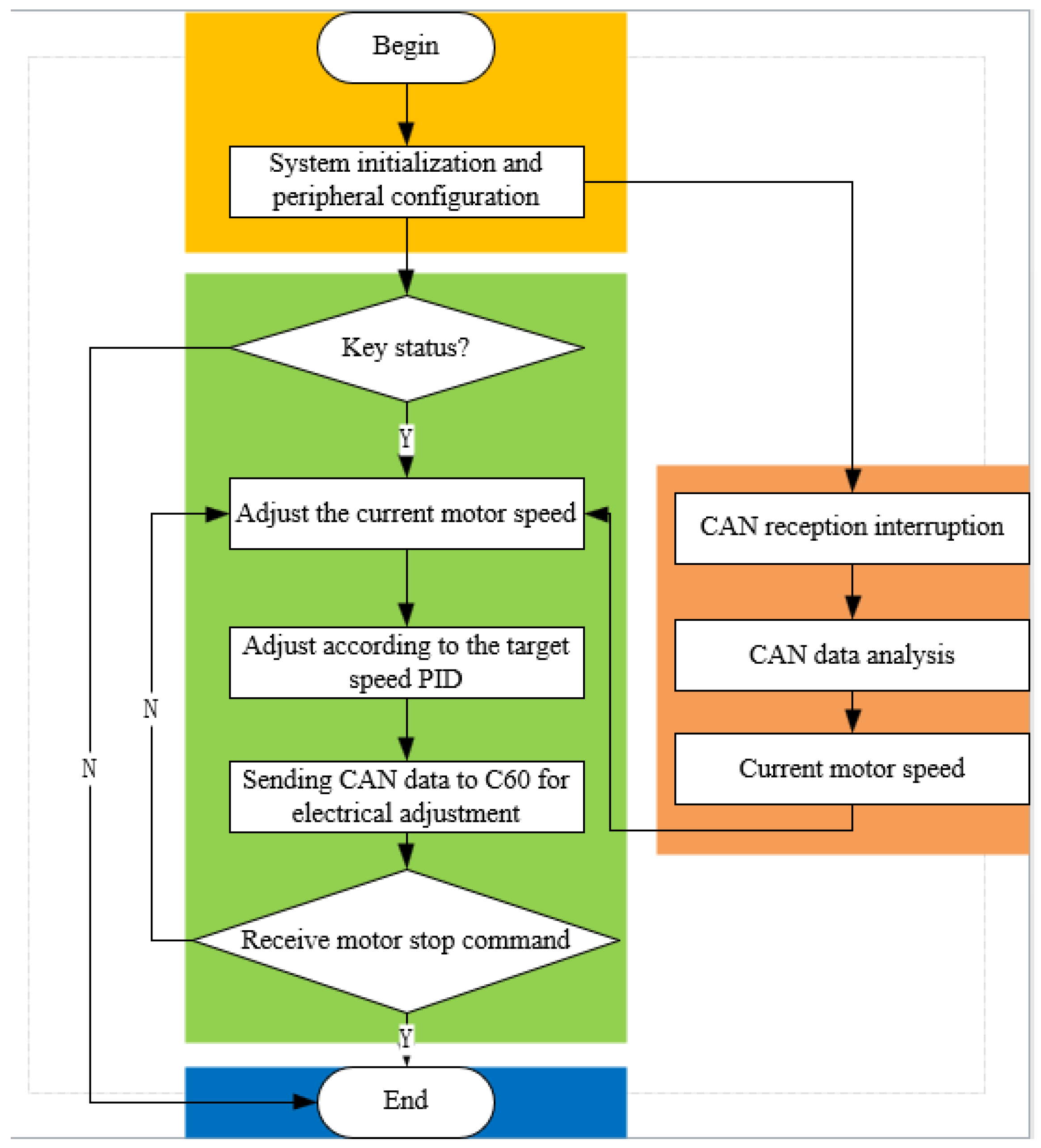
2.3. Procedure and Control System Design

When patients use S-ARR for rehabilitation training, the first step is to securely fix the S-ARR to the bed. Then, adjust the length of the calf support to match the patient’s calf length. Finally, select rehabilitation training parameters as shown in Figure 11. The control system consists of a main control module, detection module, selection module, and drive module. The USART HMI provides a graphical interface for users to complete various training tasks, such as setting motion parameters, to achieve the desired goals. The main control module uses an STM32 controller as the control core, receiving instructions and converting them into corresponding signals. The controller controls the motion of three brushless DC motors through the CAN bus, thus completing the rehabilitation training actions. Meanwhile, encoders and detection modules continuously monitor the patient’s condition to observe the user’s current information.
The control system of the ankle rehabilitation robot mainly consists of a host computer, an STM32 controller, a CAN communication module, a pressure sensor, a nine-axis IMU sensor, three sets of brushless DC motors, and multiple encoders. The nine-axis IMU sensor (N100, WHEELTEC, Dongguan, China, with an angle accuracy of 0.1 RMS) installed on the footplate, along with the thin film pressure sensor, can collect pressure data and angle information of the patient’s foot, forming the basis for force feedback and position feedback. In rehabilitation training, different key values are used to achieve the motion actions of the S-ARR. During the motion process, the real-time collected angle and position signals from the motor encoders and nine-axis IMU sensor are continuously corrected for the error between the measured and the desired projection. This ensures more precise control over the motion. The Proportional-Integral-Derivative (PID) controller is a three-term controller that is simple to use and provides efficient control performance, making it a common controller in industrial environments. The expression for the PID controller is as follows:
u c t = k P e ( t ) + k I t e τ + k D d e d t
Among them, k P , k I , and k D are the proportional gain, integral gain, and derivative gain, respectively. u c ( t ) and e ( t ) represent the output and error input of the PID controller, respectively. The control block diagram is shown in Figure 12.
According to the input instructions provided by the program, different motion actions of the rehabilitation robot are achieved through different key values. During the motion process, the real-time collected angle and position signals from the motor encoders and posture sensors are continuously corrected based on the error between the measured values and the desired trajectory, ensuring more precise control over the motion. The PID software control flowchart is shown in Figure 13.
During the patient’s rehabilitation motion process, the controller controls the motor motion based on the received signals and the control algorithm. The real joint angles of the robot are then fed back to the main control module through the motor encoders and posture sensors, forming a closed-loop control system. It can continuously monitor and adjust the patient’s rehabilitation status in real time.

3. Rehabilitation Robot Theoretical Foundations

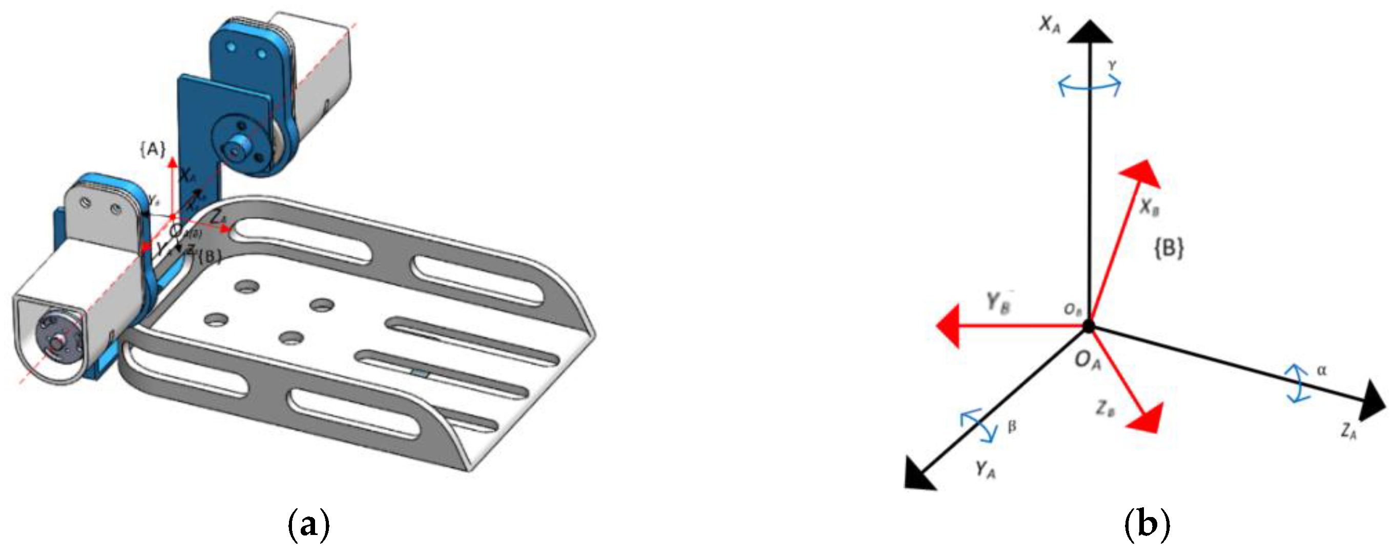
3.1. Kinematic Modeling

Kinematic analysis plays a crucial role in the workspace analysis, motion trajectory planning, and feasibility assessment of robots. Therefore, it is necessary to establish a kinematic model to analyze the relevant kinematics of the robot. The Cartesian coordinate system is established using RPY angles. Firstly, a fixed XAYAZA space rectangular coordinate system {A} is established with the robot’s rotational center as the reference frame. Its Z-axis is parallel to the footplate plane and points towards the far end of the footplate, the X-axis is perpendicular to the footplate plane and points upward, and the Y-axis is parallel to the footplate plane and points towards the right side of the footplate. At the same origin, a moving XBYBZB coordinate system {B} is established, which moves together with the platform. Its coordinate axes are similar to coordinate system {A}, representing the footplate plane after movement, as shown in Figure 14. The relationship between coordinate system B and coordinate system A describes the state of the object.
The forward kinematic analysis is as follows:
Where γ, β, and α represent the rotation angles of coordinate system B around XA, YA, and ZA, respectively.
When performing Internal/External and Dorsiflexion/Plantarflexion movements, the rotation angle around axis ZA for coordinate system {B} is 0, i.e., α = 0. Therefore, the kinematic equation can be simplified as
R X Y Z B A γ , β , α = R Z α R Y β R X γ = 1 0 0 0 1 0 0 0 1 c β 0 s β 0 1 0 s β 0 c β 1 0 0 0 c γ s γ 0 s γ c γ = c β s β s γ s β c γ 0 c γ s γ s β c β s γ c β c γ
The inverse kinematics analysis is as follows:
Given a rotation matrix derived from XYZ fixed angles represented by RPY, let
R X Y Z B A γ , β , α = r 11 r 12 r 13 r 21 r 22 r 23 r 31 r 32 r 33 = c α c β c α s β s γ s α c γ c α s β c γ + s α s γ s α c β s α s β s γ + c α c γ s α s β c γ c α s γ s β c β s γ c β c γ
First, by squaring and summing the elements (1,1) and (2,1) on both sides of the equation, we can obtain
c α c β 2 + s α c β 2 = c 2 β = r 11 2 + r 21 2
Therefore, we can conclude that
c β = ± r 11 2 + r 21 2
When cβ ≠ 0, dividing r 31 by cβ gives us tanβ. Taking the inverse tangent (arctan) of this value will give us the solution for β:
β = A tan 2 r 31 , r 11 2 + r 21 2
And, when cβ ≠ 0,
α = A tan 2 ( r 21 , r 11 ) ; β = A tan 2 r 31 , r 11 2 + r 21 2 ; γ = A tan 2 ( r 32 , r 33 )
When cβ = 0,
β = π 2 , α = 0 , γ = A tan 2 ( r 12 , r 22 )
Among them, A tan 2 ( y , x ) is a bivariate arctangent function, and its range is (−π, π]. According to the normal range of ankle joint movement in the human body and the mechanical limitations of robots, we know that 50 ° β 30 ° and c β 0 . Therefore, when performing Internal /External and Dorsiflexion/Plantarflexion movements, α = 0, and the RPY angles are
α = 0 ; β = A tan 2 r 31 , r 11 ; γ = A tan 2 ( r 32 , r 33 )

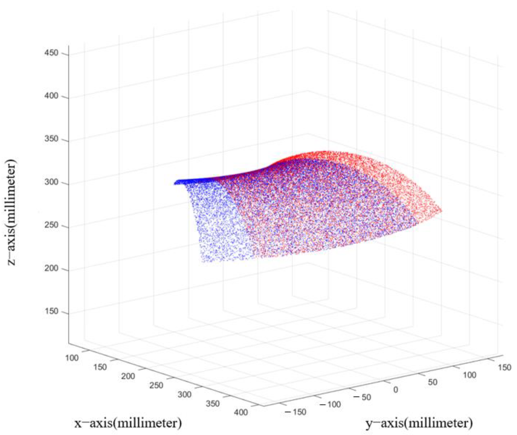
3.2. Workspace Analysis

The workspace of a robot is an important indicator for evaluating the feasibility of a robot, as it represents the robot’s range of motion and directly affects its practical application value. Based on the kinematic model of an ankle rehabilitation robot, the Monte Carlo method is used to calculate the robot’s workspace. In the parameter matrix, due to the presence of offset during joint motion, theoretically, the offset is determined based on the motion angle. The solution approach involves the robot operating within the corresponding range of angles, and the collection of random values for the far end point P of the footplate forms the robot’s workspace. The visualization of the robot’s workspace is achieved, as shown in Figure 15.
Based on the figure, it can be observed that the robot’s range of motion aligns with the physiological parameters of the human body. The simulated results of the workspace correspond to normal joint movements of the human body. The blue region in the figure represents the workspace when the left foot is being used, while the red region represents the workspace when the right foot is being used. The workspace analysis demonstrates that the robot can meet the requirements of rehabilitation training.

3.3. Robot Motion Performance Simulation

To validate the rehabilitation training capability of the robot, simulation software is utilized to simulate the robot’s stability. After importing the model, preprocessing settings are performed. The joint driving parameters of the robot are set using the step function. Post-processing analysis is then conducted using the testing module to analyze the motion speed, angular velocity, and angular acceleration for each motion mode. The simulation time is set to 8 s. The simulation results are shown in Figure 16.
From the simulation curves, it can be observed that during a simulated rehabilitation process, the ankle joint exhibits smooth changes in both the angle and angular velocity curves. This indicates that the motion of the rehabilitation training device in the simulation process starts and stops slowly and progresses smoothly. As the motor experiences instantaneous increases in angular velocity when starting and changing direction, the angular acceleration curve shows slight discontinuities at 0 s, 3 s, and 8 s, which is normal.

4. System Validation and Performance Analysis

After completing the motion simulation of the mechanism, a prototype of the supine ankle rehabilitation robot was created, as shown in Figure 17. The non-load-bearing components of the experimental prototype were produced using 3D printing, while the rest of the materials used were 6061 aluminum alloy. To verify the biomimetic and practical aspects of the supine ankle rehabilitation robot, three healthy subjects were recruited for this study, and their physical information is presented in Table 3. All subjects had no neurological impairments. After wearing the experimental prototype, the subjects underwent experiments for joint range of motion measurement and rehabilitation exercises.

4.1. Joint Range of Motion Measurement Experiment

The joint range of motion measurement experiment is primarily conducted to obtain the ankle joint movement range of the wearer during rehabilitation training using the rehabilitation robot. In the passive control mode, Subject 1 and Subject 2 performed five rehabilitation movements in the supine position using the robot. The extreme positions of each movement were captured by a camera, and then the ankle joint range of motion for the subjects was measured based on the calibrated markers on the human body, as shown in Figure 18 and Figure 19. Here, the ankle Dorsiflexion range of motion is represented by the symbol α, the ankle Plantarflexion range of motion is represented by the symbol β, the ankle Inversion range of motion is represented by the symbol γ, and the ankle Eversion range of motion is represented by the symbol θ. By processing the images, the angles of each joint for each movement were determined and averaged, as shown in Table 4 and Table 5.
By comparing the measured joint ranges of motion with the simulated joint ranges of motion, it can be observed that the measured joint ranges of motion are slightly smaller than the normal ranges by approximately 2°. This is because the human body is not a rigid body, and there is slight movement when wearing the robot. Additionally, to ensure wearer comfort, the straps cannot be excessively tightened, resulting in a small gap between the wearer and the device during movement. Overall, the joint range of motion measurement results fluctuate within an acceptable range, demonstrating that the prototype can meet the requirements of rehabilitation.

4.2. Rehabilitation Training Experiment

To validate the practicality of the supine ankle rehabilitation robot, a rehabilitation training platform was set up, as shown in Figure 20. This platform was used to test the motion performance of the supine ankle rehabilitation robot. During the testing process, Subject 1 and Subject 3 were tested separately in a supine position without the use of their own strength. A nine-axis IMU sensor was used to monitor the patient’s posture and obtain the motion performance of the robot, as shown in Figure 21 and Figure 22.

5. Conclusions and Future Work

This study proposes a simple and portable supine ankle rehabilitation robot (S-ARR) that can adapt to patients with different physical conditions and is used for early-stage ankle rehabilitation after a stroke. The main conclusions are as follows:
(1)
The kinematic model of the robot was established, and simulation analysis was conducted on the ankle joint rotation angle, angular velocity, and angular acceleration curves. The simulation analysis of the S-ARR workspace demonstrated its ability to meet the training needs of patients. The analysis confirmed the rationality and feasibility of the mechanism design.
(2)
A prototype system was constructed, and joint range of motion measurement experiments were conducted. The results showed that the measured joint angles were slightly smaller than the preset values (approximately 2°). The fluctuations in the measured joint range of motion were within an acceptable range, indicating that the prototype could meet the rehabilitation requirements. The rehabilitation training experiments demonstrated the smooth operation of the robot, with the maximum angle slightly smaller than the specified angle, achieving satisfactory performance for supine rehabilitation training.
This robot can be used for early-stage rehabilitation training, saving rehabilitation time and improving rehabilitation outcomes. Future work will focus on further optimizing the structural design and control methods of S-ARR. Clinical trials will be conducted to validate the effectiveness of active training and rehabilitation after functional completion. Stroke rehabilitation for patients with functional impairments is a complex process, particularly in terms of scale control during early-stage rehabilitation training. Future directions will include hierarchical control of the supine ankle rehabilitation robot and the design of adjustable angle structures to meet the requirements of ankle rehabilitation at different stages. This will involve increasing the degrees of freedom of the robot and ensuring alignment between the rotation center of the ankle joint and the rotation center of the supine ankle rehabilitation robot. The development of the control system will incorporate compliant control to achieve active training, passive training, and assistive training modes for the supine ankle rehabilitation robot. In further designs, the use of soft actuators and materials will be considered to develop subsequent versions of rehabilitation devices, which can provide patients with increased safety and comfort.
Future work will also include the application of plantar electrical stimulation systems and the integration of various sensors (such as electromyographic signals) to intelligently monitor ankle joint movements during rehabilitation training. Based on these measurements, real-time assessment of ankle joint function can be performed. Additionally, unforeseen circumstances such as abnormal muscle tension resulting in unusual forces can be addressed by the robot through sensor-based evaluation. Depending on the evaluation results, the robot can decide whether to stop its operation and update the rehabilitation training plan, allowing patients to engage in adaptive rehabilitation training at an early stage. Another potential direction is the integration of virtual reality technology to enhance the enjoyment of the rehabilitation training process. In the future, this system will not only improve the smoothness of training but also enhance patient engagement, promote interaction between perception and learning, and ultimately improve the effectiveness of rehabilitation therapy.

Author Contributions

Conceptualization, Q.M. (Qingyun Meng) and Q.M. (Qiaoling Meng); methodology, Q.M. (Qingyun Meng) and H.Y.; software, G.L. and X.X.; validation, X.X. and G.L.; formal analysis, Q.M. (Qingyun Meng), G.L. and X.X.; writing—original draft preparation, Q.M. (Qingyun Meng) and G.L.; writing—review and editing, Q.M. (Qingyun Meng) and X.X.; visualization, Q.M. (Qingyun Meng) and G.L.; resources, Q.M. (Qiaoling Meng) and H.Y.; supervision, Q.M. (Qiaoling Meng) and H.Y.; project administration, Q.M. (Qingyun Meng) and Q.M. (Qiaoling Meng); funding acquisition, H.Y. All authors have read and agreed to the published version of the manuscript.

Funding

This research was funded by the National Key R&D Program of China (2020YFC2007501) and the National Key R&D Program of China (2022YFC3601403).

Data Availability Statement

The original data contributions presented in this study are included in the article. Further inquiries can be directed to the corresponding authors. Figure 1 and Figure 2 were modified from Servier Medical Art (http://smart.servier.com/ (accessed on 20 July 2023)), licensed under a Creative Common Attribution 3.0 Generic License. (https://creativecommons.org/licenses/by/3.0/ (accessed on 20 July 2023)).

Conflicts of Interest

The authors declare no conflict of interest.

References

  1. Feigin, V.L.; Stark, B.A.; Johnson, C.O.; Roth, G.A.; Bisignano, C.; Abady, G.G.; Hamidi, S. Global, regional, and national burden of stroke and its risk factors, 1990–2019: A systematic analysis for the Global Burden of Disease Study 2019. Lancet Neurol. 2021, 20, 795–820. [Google Scholar] [CrossRef]
  2. Markus, H.S. Reducing disability after stroke. Int. J. Stroke 2022, 17, 249–250. [Google Scholar] [CrossRef]
  3. Grefkes, C.; Fink, G.R. Recovery from stroke: Current concepts and futures perspectives. Neurol. Res. Pract. 2020, 2, 17. [Google Scholar] [CrossRef]
  4. Gassert, R.; Dietz, V. Rehabilitation robots for the treatment of sensorimotor deficits: A neurophysiological perspective. J. NeuroEng. Rehabil. 2018, 15, 46. [Google Scholar] [CrossRef] [Green Version]
  5. Shi, M.; Yang, C.; Zhang, D. A novel human-machine collaboration model of an ankle joint rehabilitation robot driven by EEG signals. Math. Probl. Eng. 2021, 2021, 5564235. [Google Scholar] [CrossRef]
  6. Flansbjer, U.B.; Holmbck, A.M.; Downham, D.; Patten, C.; Lexell, J. Reliability of gait performance in men and women with hemiparesis after stroke. J. Rehabil. Med. 2005, 37, 75–82. [Google Scholar]
  7. Dao, M.D.; Tran, X.T.; Pham, D.P.; Ngo, Q.A.; Le, T.T.T. Study on the ankle rehabilitation device. Arch. Mech. Eng. 2022, 69, 147–163. [Google Scholar]
  8. Li, J.; Zuo, S.; Zhang, L.; Zhang, L.; Dong, M.; Zhang, Z.; Tao, C.; Ji, R. Mechanical design and performance analysis of a novel parallel robot for ankle rehabilitation. J. Mech. Robot. 2020, 12, 051007. [Google Scholar] [CrossRef]
  9. Jiang, J.; Min, Z.; Huang, Z.; Ma, X.; Chen, Y.; Yu, X. Research Status on Ankle Rehabilitation Robot. Recent Pat. Mech. Eng. 2019, 12, 104–124. [Google Scholar] [CrossRef]
  10. Engineering, J.H. Retracted: Design and Workspace Analysis of a Parallel Ankle Rehabilitation Robot (PARR). J. Healthc. Eng. 2021, 2021, 7345780. [Google Scholar] [CrossRef]
  11. Farjadian, A.B.; Nabian, M.; Hartman, A.; Yen, S.C. Vi-RABT: A Platform-Based Robot for Ankle and Balance Assessment and Training. J. Med. Biol. Eng. 2018, 38, 556–572. [Google Scholar] [CrossRef]
  12. Cioi, D.; Kale, A.; Burdea, G.; Engsberg, J.; Janes, W.; Ross, S. Ankle control and strength training for children with cerebral palsy using the Rutgers ankle CP: A case study. In Proceedings of the 2011 IEEE International Conference on Rehabilitation Robotics (ICORR), ETH Zurich, Zurich, Switzerland, 27 June–1 July 2011; pp. 654–659. [Google Scholar]
  13. Lei, Y. Development of Ankle Rehabilitation Training Device and Evaluation of Rehabilitation Effect. Master’s Thesis, Dalian University of Technology, Dalian, China, 2021. [Google Scholar]
  14. Mayetin, U.; Kucuk, S. Design and Experimental Evaluation of a Low Cost, Portable, 3-DOF Wrist Rehabilitation Robot with High Physical Human–Robot Interaction. J. Intell. Robot. Syst. 2022, 106, 65. [Google Scholar] [CrossRef]
  15. Curcio, E.M.; Carbone, G. Mechatronic design of a robot for upper limb rehabilitation at home. J. Bionic Eng. 2021, 18, 857–871. [Google Scholar] [CrossRef]
  16. Reza, M.; Sally, E.; Catherine, C.; Anna, S.; Aseem, J.; Emmanuel, W.; Kevin, C. Robotically assisted ankle rehabilitation for pediatrics. In Proceedings of the 6th IEEE RAS/EMBS International Conference on Biomedical Robotics and Bio Mechatronics, Bio Rob 2016, Singapore, 26–29 June 2016; pp. 612–616. [Google Scholar]
  17. Kevin, C.; Reza, M.; Tyler, S.; Hadi, F.T.; Catherine, C.; Staci, K.; Justine, B.; Sara, A.; Manon, S.; Sarah, H.E. Pedbothome: Robotically-assisted ankle rehabilitation system for children with cerebral palsy. In Proceedings of the 16th IEEE International Conference on Rehabilitation Robotics, ICORR 2019, Toronto, ON, Canada, 24–28 June 2019; pp. 13–20. [Google Scholar]
  18. Lim, F.M.; Ruyi, F.; Goh, K.S.; Mok, Q.L.; Tan, B.H.J.; Toh, S.L.; Yu, H. Supine Gait Training Device for Stroke Rehabilitation–Design of a Compliant Ankle Orthosis. In Proceedings of the 15th International Conference on Biomedical Engineering, ICBME 2013, Singapore, 4–7 December 2013; pp. 512–515. [Google Scholar]
  19. Li, J.; Fang, Q.; Dong, M.; Rong, X.; Jiang, L.; Jiao, R. Reconfigurable Muscle Strength Training Robot with Multi-mode Training for 17 Joint Movements. J. Bionic Eng. 2023, 20, 212–224. [Google Scholar] [CrossRef]
  20. Tommaso, P.; Ciaran, O.; Lucas, G.; Tazzy, C.; Sarah, M.; Kristin, N.; Cameron, H.; David, L.; Sabrina, P.; Conor, W. Restoring arm function with a soft robotic wearable for individuals with amyotrophic lateral sclerosis. Sci. Transl. Med. 2023, 15, eadd1504. [Google Scholar]
  21. Panagiotis, P.; Zheng, W.; Kevin, C.G.; Robert, J.W.; Conor, J.W. Soft robotic glove for combined assistance and at-home rehabilitation. Robot. Auton. Syst. 2015, 73, 135–143. [Google Scholar]
  22. Zachary, Y.; Nicholas, K.; Christina, C.M.; Devon, R.; Shane, K.M.; Madison, B.E.; Richard, F.W.; Jacob, S.; Christoph, K. Design of a High-Speed Prosthetic Finger Driven by Peano-HASEL Actuators. Front. Robot. AI 2020, 7, 586216. [Google Scholar]
  23. Zhang, M.; Cao, J.; Zhu, G.; Miao, Q.; Zeng, X.; Xie, S. Reconfigurable workspace and torque capacity of a compliant ankle rehabilitation robot (CARR). Robot. Auton. Syst. 2017, 98, 213–221. [Google Scholar] [CrossRef] [Green Version]
  24. Gallagher, J.F.; Sivan, M.; Levesley, M. Making Best Use of Home-Based Rehabilitation Robots. Appl. Sci. 2022, 12, 1996. [Google Scholar] [CrossRef]
  25. Yu, H.; Zheng, S.; Wu, J.; Sun, L.; Chen, Y.; Zhang, S.; Qin, Z. A New Single-Leg Lower-Limb Rehabilitation Robot: Design, Analysis and Experimental Evaluation. Machines 2023, 11, 447. [Google Scholar] [CrossRef]
  26. Khan, M.A.; Saibene, M.; Das, R.; Brunner, I.; Puthusserypady, S. Emergence of flexible technology in developing advanced systems for post-stroke rehabilitation: A comprehensive review. J. Neural Eng. 2021, 18, 061003. [Google Scholar] [CrossRef] [PubMed]
  27. Meng, W.; Liu, Q.; Zhou, Z.; Ai, Q. Active interaction control applied to a lower limb rehabilitation robot by using EMG recognition and impedance model. Ind. Robot-Int. J. Robot. Res. Appl. 2014, 41, 465–479. [Google Scholar] [CrossRef]
  28. Sheng, B.; Tang, L.; Moosman, O.M.; Deng, C.; Xie, S.; Zhang, Y. Development of a biological signal-based evaluator for robot-assisted upper-limb rehabilitation: A pilot study. Australas. Phys. Eng. Sci. Med. 2019, 42, 789–801. [Google Scholar] [PubMed]
  29. Zhou, J.; Yang, S.; Xue, Q. Lower limb rehabilitation exoskeleton robot: A review. Adv. Mech. Eng. 2021, 13, 16878140211011862. [Google Scholar] [CrossRef]
  30. Bernhardt, J.; Indredavik, B.; Langhorne, P. When Should Rehabilitation Begin after Stroke? Int. J. Stroke 2013, 8, 5–7. [Google Scholar] [CrossRef]
  31. Coleman, E.R.; Moudgal, R.; Lang, K.; Hyacinth, H.I.; Awosika, O.O.; Kissela, B.M.; Feng, W.W. Early Rehabilitation After Stroke: A Narrative Review. Curr. Atheroscler. Rep. 2017, 19, 59. [Google Scholar]
  32. Sun, Z.; Wang, C.; Wei, J.; Xia, J.; Wang, T.; Liu, Q.; Duan, L.; Wang, Y.; Long, J. Kinematics and Dynamics Analysis of a Novel Ankle Rehabilitation Robot. In Proceedings of the 2019 IEEE 9th Annual International Conference on CYBER Technology in Automation, Control, and Intelligent Systems (CYBER), Suzhou, China, 29 July–2 August 2019; pp. 1404–1409. [Google Scholar]
Figure 1. Skeletal structure of the ankle joint.
Machines 11 00787 g001
Figure 2. The movements of the human ankle joint.
Machines 11 00787 g002
Figure 3. Mechanism of the ankle rehabilitation robot.
Machines 11 00787 g003
Figure 4. Motion function components.
Machines 11 00787 g004
Figure 5. Transmission components for Dorsiflexion/Plantarflexion.
Machines 11 00787 g005
Figure 6. Transmission components for Internal/External.
Machines 11 00787 g006
Figure 7. Fixed support component.
Machines 11 00787 g007
Figure 8. Three-dimensional model of patient using S-ARR.
Machines 11 00787 g008
Figure 9. Mechanical limitation diagram for Internal and External rotation. (a) Schematic diagram of limitation structure. (b) Limitation device for left foot rehabilitation training. (c) Limitation device for right foot rehabilitation training.
Machines 11 00787 g009
Figure 10. Adjustable calf support. (a) Shortest position. (b) Longest position.
Machines 11 00787 g010
Figure 11. S-ARR utilization process and control system scheme.
Machines 11 00787 g011
Figure 12. PID control block diagram.
Machines 11 00787 g012
Figure 13. PID control software flowchart.
Machines 11 00787 g013
Figure 14. Robot coordinate diagram. (a) Model coordinate diagram. (b) Coordinate simplified diagram.
Machines 11 00787 g014
Figure 15. Robot’s operational workspace.
Machines 11 00787 g015
Figure 16. Motion performance simulation. (a) Variation of motion angle. (b) Variation of motion angular velocity. (c) Variation of motion angular acceleration.
Machines 11 00787 g016aMachines 11 00787 g016b
Figure 17. S-ARR prototype.
Machines 11 00787 g017
Figure 18. Joint angle measurement for Subject 1. (a) Dorsiflexion angle measurement. (b) Plantarflexion angle measurement. (c) Internal angle measurement. (d) External angle measurement.
Machines 11 00787 g018
Figure 19. Joint angle measurement for Subject 2. (a) Dorsiflexion angle measurement. (b) Plantarflexion angle measurement. (c) Internal angle measurement. (d) External angle measurement.
Machines 11 00787 g019
Figure 20. Rehabilitation training testing platform.
Machines 11 00787 g020
Figure 21. Ankle joint angle variation for Subject 1. (a) Dorsiflexion/Plantarflexion motion. (b) Internal/External motion.
Machines 11 00787 g021
Figure 22. Ankle joint angle variation for Subject 3. (a) Dorsiflexion/Plantarflexion motion. (b) Internal/External motion.
Machines 11 00787 g022
Table 1. Mechanical structure comparison with other ankle rehabilitation robots.
FeaturesS-ARRvi-RABTDevice [7]CARRTrainer [13]
TypePlatform-basedPlatform-basedPlatform-basedPlatform-basedPlatform-based
SizeLittleLittleModerateModerateModerate
Single foot/
Double foot
SingleSingleSingleSingleDouble
Driving methodMotor driveMotor driveMotor driveFlexible driveMotor drive
PostureSitting and lyingSittingSittingSittingLying
Usage patternsCombining with the bedFixed
Position
Fixed seatFixed
Position
Combining with the bed
MobilityEasyEasyHarderHarderEasy
Table 2. The parameters of ankle movements.
MotionAngle Range (°)
Internal0~20
External0~30
Dorsiflexion0~30
Plantarflexion0~50
Inversion0~40
Eversion0~30
Table 3. Participant body data.
IDGenderAgeHeightWeight
1Male25175 cm60 kg
2Female25160 cm42 kg
3Male26180 cm65 kg
Table 4. Range of motion of the joints for Subject 1.
Angle12345Mean
α49.549.749.248.849.349.3
β29.428.729.628.829.629.2
γ19.819.619.218.519.419.3
θ28.829.728.929.029.329.1
Table 5. Range of motion of the joints for Subject 2.
Angle12345Mean
α48.749.349.448.648.548.9
β28.429.228.528.929.528.9
γ19.218.718.518.319.018.7
θ28.429.028.628.328.528.6
Disclaimer/Publisher’s Note: The statements, opinions and data contained in all publications are solely those of the individual author(s) and contributor(s) and not of MDPI and/or the editor(s). MDPI and/or the editor(s) disclaim responsibility for any injury to people or property resulting from any ideas, methods, instructions or products referred to in the content.

