1. Introduction
Robotics can be applied to not only in large engineering companies, but thanks to its availability, it can also reach the medium and smaller manufacturing companies. The advantage of using robots is their complexity and adaptability within the manufacturing process. After a certain period, a robot that performs work directly in the manufacturing process may lose its declared accuracy and repeatability for various reasons, such as an arm overload or irregular calibration [
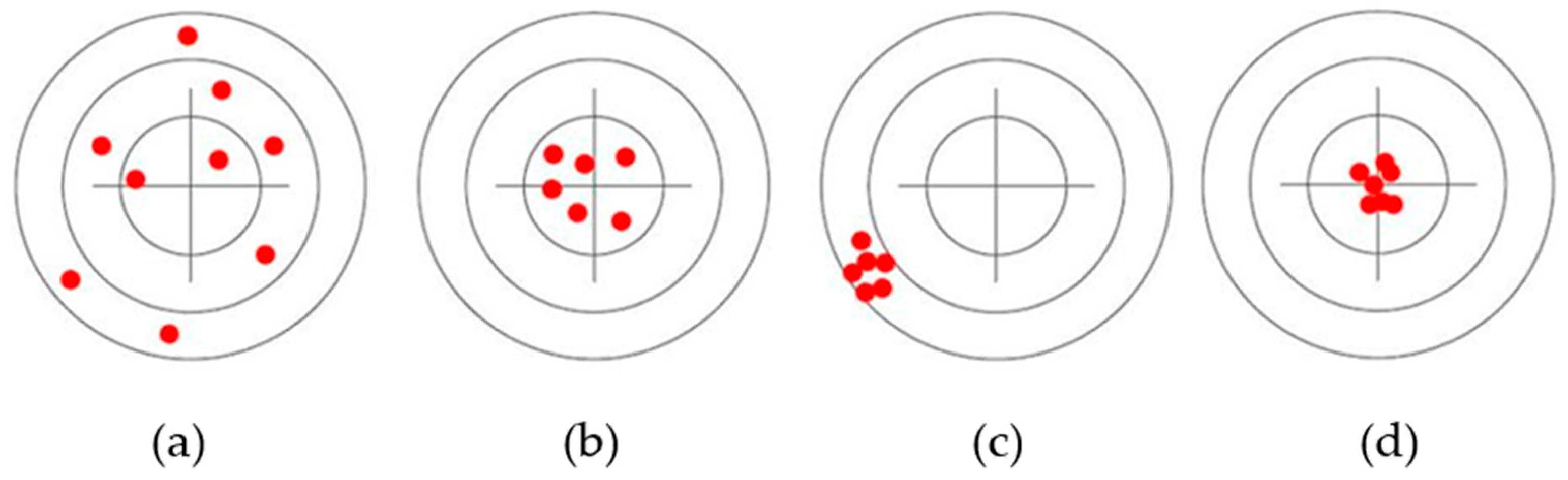
1]. The main performance characteristics of the robots to be monitored are the repeatability, payload, reach, and positioning accuracy (
Figure 1) [
2,
3].
Payload is defined as the weight that the robot can carry without causing variations in other specifications, such as accuracy, during the execution of the task. The maximum payload of the robotic arm can be greater than the specified payload. At a load greater than the useful load, the robot will likely be less accurate, experience a problem with the trajectory of the motion, or have large deviations [
4]. An example is the specification of a robot where the maximum payload specified by the manufacturer is 6 kg, which means that the robot has been tested at 6 kg, the weight at which it has achieved the best results. This weight should not be exceeded to avoid positioning errors [
5].
Reach can be defined as the maximum distance the robot can reach within its working area [
6]. The cubes’ function, the robot arm’s length, and other robot configurations condition the robot’s reach. The parameters provided by the manufacturer only give the maximum range, which is a rough estimate of the workspace. In practice, it is common for a robot to have a greater reach in one direction than in the other. Therefore, the robot’s reach is very important in terms of robot selection [
7,
8].
Accuracy is generally defined as the error between the programmed, i.e., desired, position and the actual position of the robot endpoint. Accuracy is not always paramount when using a robot, meaning that if the robot is programmed manually, where the worker teaches the robot all the points to reach, accuracy does not play a major role. However, the positioning accuracy of the robot is particularly important when it is used in a market where it has to be programmed according to a CAD model, as the endpoint has to be reached in precisely defined positions [
9].
The repeatability of a robot expresses how accurately the robot can reach the same position if the motion is repeated several times. The repeatability of a position is affected by the robot’s precision. For example, when testing a robot where a desired position is selected and repeated 30 times, the robot will not always reach the same position. However, deviations will occur, and the robot will move near the desired point. The radius that is formed by the repeated movements is termed the repeater. A certain number of repetitive cycles usually form this robot characteristic. The more repetitions that are performed, the worse the results obtained. Robot manufacturers specify the tests they have performed with a certain number of cycles, payload, and arm orientation [
10].
2. State of the Art
The problems in evaluating the performance characteristics of robots, such as unidirectional precision and the robot’s position, is currently being addressed by many research teams and manufacturing departments worldwide. The measurement itself can take place directly in the manufacturing plants, as well as in the laboratory columns.
In an experiment conducted by Sepehr Gharaaty et al., the positioning accuracy of two industrial robots, specifically the FANUC LR Mate 200iC and the FANUC M20iA, was investigated. The authors solved the problem by designing a dynamic position correction scheme. This dynamic position correction scheme works by obtaining a feedback loop through which the change in positioning is through the projected robotic arm. The authors used the C-Track 780 optical coordinate system from Creaform for positioning. The algorithm was designed for use on a six-axis robot performing stationary tasks. As a result of the designed and tested system, the real-time positioning accuracy of the six-axis industrial robot greatly improved. Thus, the proposed algorithm can improve the positioning accuracy of robots in tasks, such as welding, riveting, and threading. The authors’ vision for further research is to adapt this algorithm to other industrial robot manufacturers, such as ABB and Kuka [
11].
In their experiment, Albert Nubiola et al. compared two metrology devices to calibrate an industrial robot. The metrology devices used were the FARO laser tracker and the Creaform C-Track. These calibrations were performed on an ABB IRB 120 industrial robot. The main difference between these devices is that the C-Track device works on the principle of photogrammetry. Through experimentation, the authors reduced the position error by almost 5 mm on average. At the same time, the authors pointed out the ease of use and the more affordable option of calibration with the Creaform C- Track device [
12].
An experiment by Mohamed Slamani et al. investigated the positioning accuracy and repeatability of a six-axis ABB IRB 1600 industrial robot. The design of the test conditions was based on the ISO 9283 standard, which focuses on assessing the performance parameters of industrial robots. The authors used a trio of metrology devices: a laser tracker, a laser interferometer, and a Renishaw ballbar test. Using the laser tracker, the repeatability was measured in the range from 22 to 37 mm, respectively. The repeatability was measured between 6 and 14 mm using the Renishaw laser interferometer. The last device used was the circular ballbar test, with which a circularity deviation was measured within 1 mm. Of all the metrology devices used, the authors chose the circular ballbar test as the most suitable, as it is an accurate and affordable device that can measure industrial robots’ static and dynamic parameters [
13].
In a paper by Jerzy Józwik et al., they tested a repeatability of the Yaskawa Motoman HP20F industrial six-axis robot. They used a Phantom v2511 high-speed camera to measure the repeatability. The measurement principle was based on tracking the designed points and subsequent image analysis using the TEMA MOTION software. The measurement was performed in two planes, X and Y, respectively. The measured deviations were then added to the formulas according to ISO 9283. The result of this experiment was that as the number of cycles increased, the robot achieved a worsened repeatability. At the same time, the manufacturer’s declared repeatability was RP = 0.06 mm, but the authors measured a repeatability that was several hundredths of a millimeter worse at several points [
14].
In their experiment, the Michal Vocetka et al. investigated the effects of thermal expansion on the design of an industrial robot in order to reduce the difference in robot repeatability at low and high temperatures. The robot chosen for the experiment was an ABB IRB 1200 5/0.9. The authors proposed a compensation methodology to reduce the effect of drift on the robot’s repeatability. A diagram incorporated in front of the robot control unit was able to evaluate and adjust the robot’s position. As a result of the experiment, the robot’s repetitive drift was reduced by almost 85% with the proposed compensation methodology. Prior to the introduction of the methodology, the repeatability was in the neighborhood of 200 µm; after the introduction, it was in the range of 25 µm at any temperature. Moreover, with the proposed methodology, the robot can be used immediately after startup, and there is no need to wait for the robot to warm up to the operating temperature [
15].
3. Testing of Performance Characteristics According to ISO 9283
ISO 9283 describes the test methods for determining the performance characteristics of industrial robots. The standard contains 14 tests that can be used to develop, test, or compare industrial robots. The number of measurement points and cycles characterizes each test. The tests are described in detail to determine the correct measurement conditions to be observed. Each performance test must be performed at the maximum possible load and speed. The standard itself does not specify what metrology system should be used to measure the characteristics, which can be seen as a benefit as being more affordable, and accurate measurement systems can be used. The most common characteristics assessed are the unidirectional position accuracy (AP), unidirectional position repeatability (RP), path repeatability (RT), distance accuracy (AD), and distance repeatability (RD). Most manufacturers of industrial robots test to this standard. However, only positional repeatability is specified by manufacturers in the robot selection specifications. Most of the characteristics are tested using an imaginary ISO cube inserted into the robot’s workspace so that it is where the robot most often operates [
16,
17,
18].
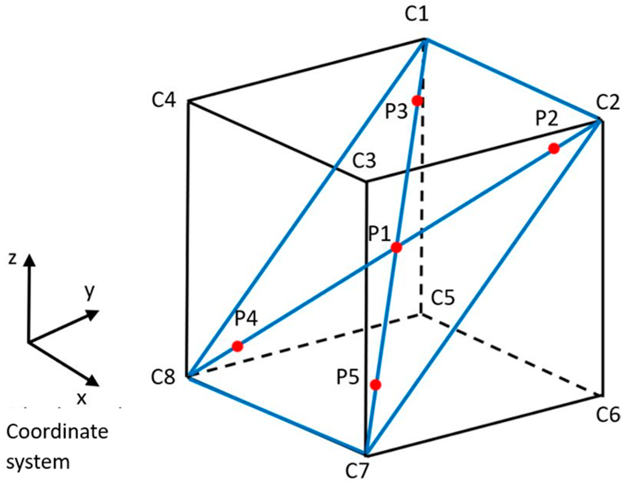
In
Figure 2, it is possible to see a cube on which a diagonal has been chosen to perform the tests using the points C1 to C8. In this example, these are points C1–C2–C7–C8. The next step is to select the measurement points, the number of which may vary depending on the characteristic being measured. In this example, the measured characteristic was unidirectional position accuracy. For the measurement, five measurement points (P1–P5) have been selected [
16,
17].
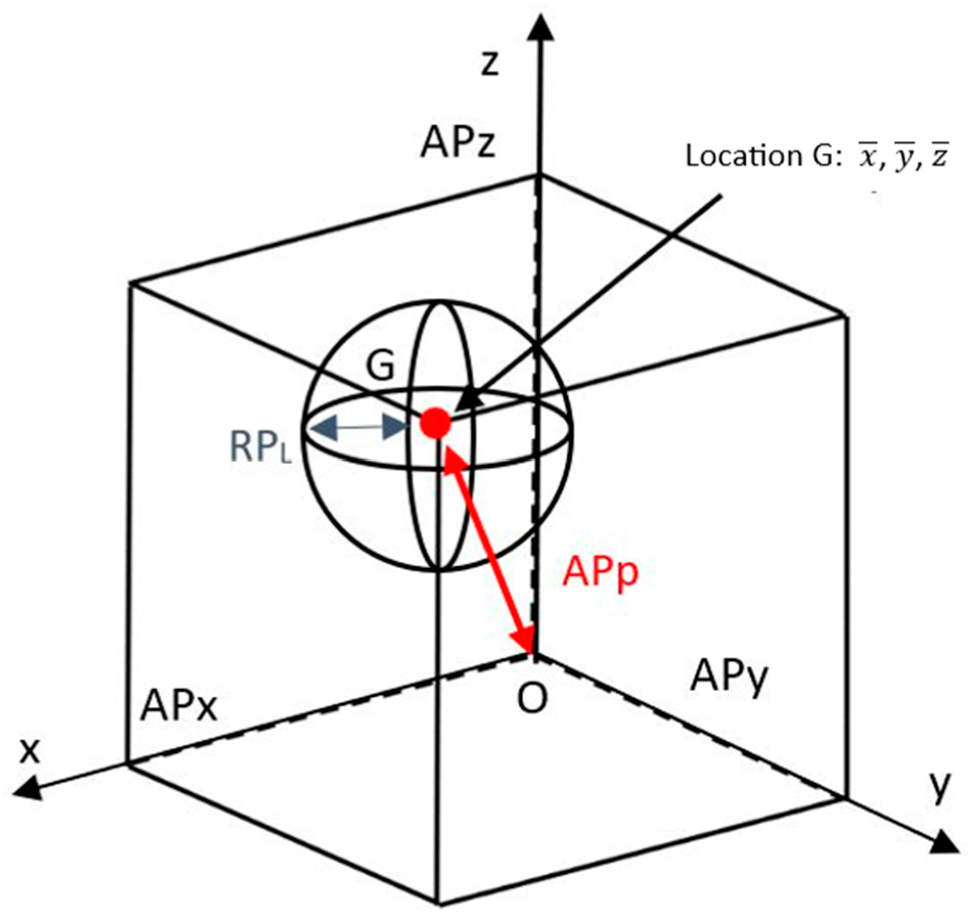
Unidirectional position accuracy (AP): position accuracy is defined in the standard as the deviation between the desired position and the mean achieved value of the desired position (
Figure 3). When performing the test, it is necessary to comply with the specified measurement conditions set out in the standard (
Table 1): the mass of the maximum payload, the speed, and the number of repetitions [
16,
17,
18].
Unidirectional positioning precision (
APp): the difference between the desired position and the range of positions achieved. The positioning accuracy is given by Equation (1):
where
, represent the coordinates of the focal point obtained for a certain position after performing
n number of cycles, and
(Equation (2)) represent the measured values. The terms
,
, and
represent the coordinates of the controlled, i.e., programmed, position [
16].
- 2.
Unidirectional position repeatability (RP): according to the above-mentioned standard, position repeatability is expressed as the difference between the positions reached after
n cycles performed in the same direction for the same position [
16,
18]. For testing, the same conditions apply, as written in
Table 1.
The unidirectional repeatability of the positioning is expressed by the
RPl value, and is calculated as shown in the following Equation (3):
where
represents the mean of the variable
L, and
Sl represents the standard deviation
and
,
,
is defined in Equation (4).
4. Methodology
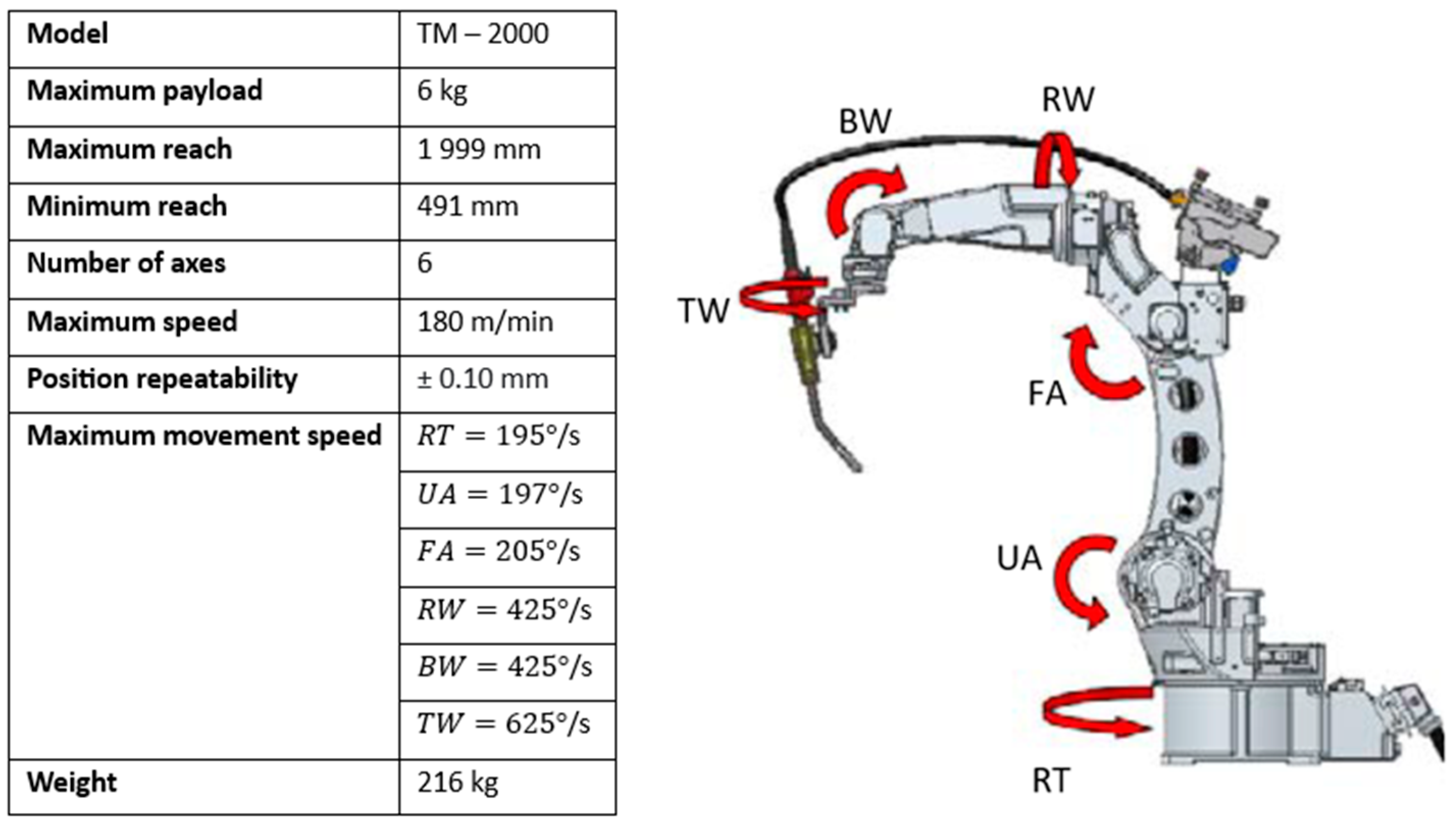
4.1. Panasonic TM 2000 Industrial Robot
Panasonic manufactures and supplies several series of robots. The TM series of robots were designed primarily for welding processes. The mentioned welding robot series came with several improvements, such as the possibility of cable routing to the torch (internal and external) and stronger and more stable robot construction. The main improvement over the older types, where an absolute encoder was used on the servomotor, is using a high-precision smart encoder, which ensures a better track accuracy and more precise weld execution. The basic parameters of the used welding robot given by the manufacturer are presented in
Figure 4.
The primary software for programming and controlling Panasonic robots is the DTPS software. This software has been exclusively designed for Panasonic industrial robots for offline programming. In this software, it is possible to create an overall welding design with cycle counts and welding times and simulate the manufacturing process. The advantage of these simulation programs is the prevention of possible collisions with the robotic equipment. This means that when directly programming from the CAD model, the worker can change the welding torch’s orientation to avoid unwanted robot positions. The software supports multiple formats for CAD model insertion (STL, IGES, IGS, and DXF). Panasonic has also incorporated robot and external positioner axis calibration into the software.
4.2. Design of Measuring Equipment, ISO Cubes, and the Selection of the Test Conditions
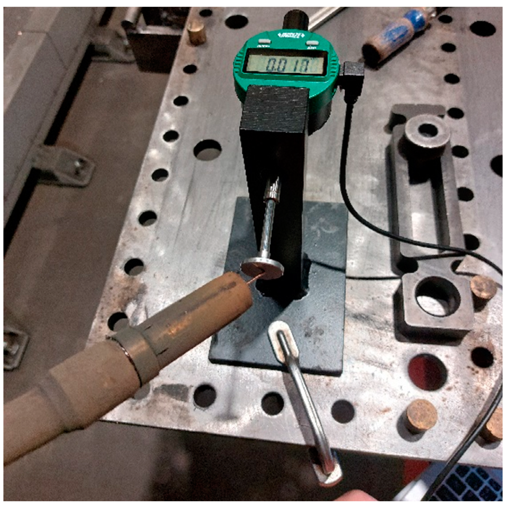
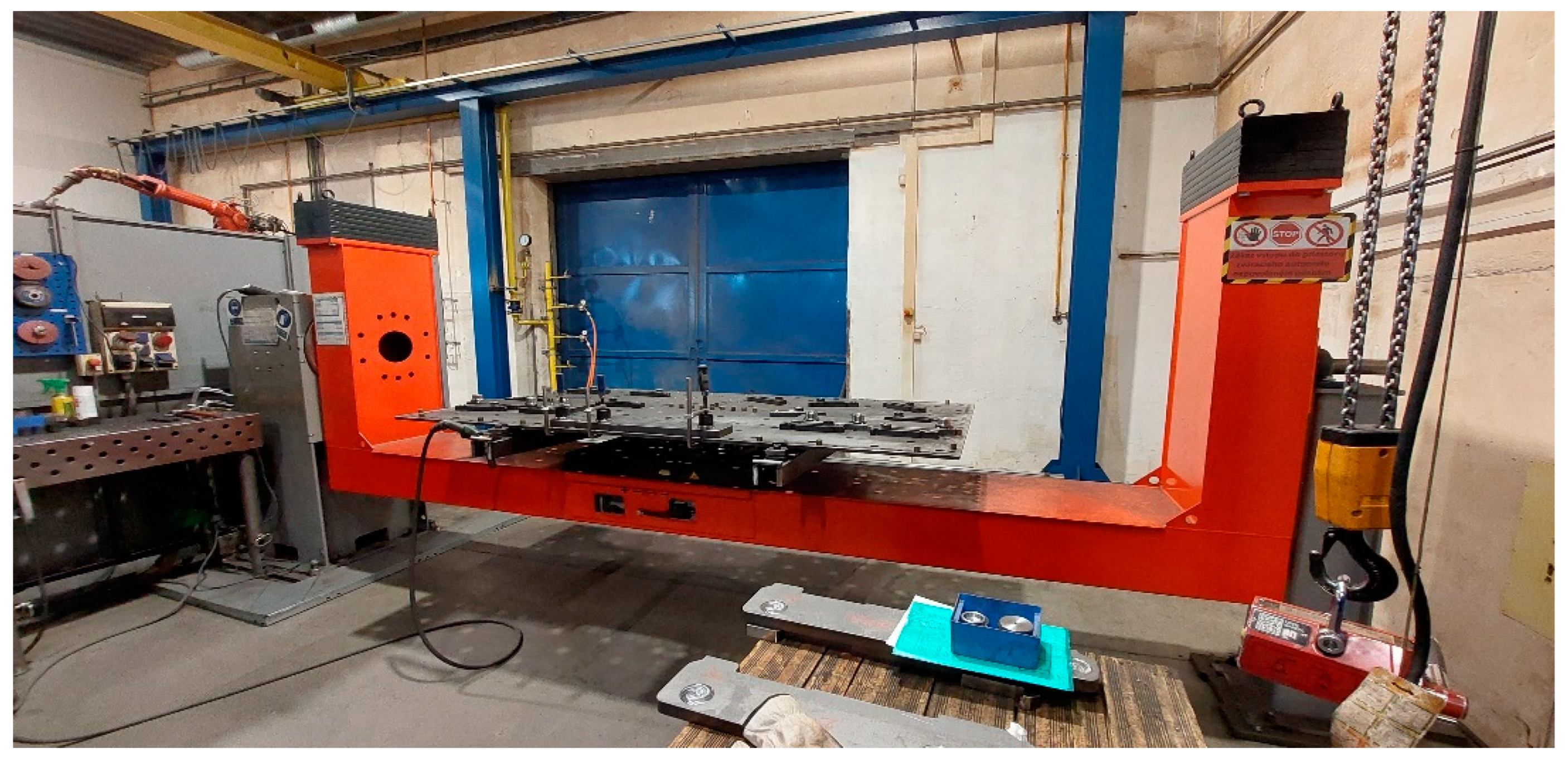
A digital strain gauge from INSIZE, model 2112-254F, was used to implement the column measurements. It is an accurate, simple, and affordable measuring device. It has an accuracy of 0.005 mm, a measuring range of 25.4 mm, and a digital step of 0.001 mm for digital measurements, potentially storing the data in the form of a table of values directly on the PC. As the repeatability was measured on a welding robot having a welding wire at the end of the welding nozzle, a 20 mm diameter contact area was chosen for the repeatability measurement due to the impossibility of attaching another suitable object, e.g., a precision machined cube, to the end of the robotic arm. A fixture was subsequently designed and fabricated to fix the measuring device to the welding table. The complete design of the measuring station in real conditions in the production hall is shown in
Figure 5.
Once the measurement system was selected, designing an ISO cube with a selected measurement plane and five measurement points was the next necessary step. The dimensions of the ISO cube were determined based on the robot’s workspace and where the robot most often welds. The length of the edge was 1200 mm. This type of welding robot uses the “touch sensing” function, which means that the robot locates the position of the workpiece to be welded before welding. This type of smoothing is entered directly when programming the welding task of the robot. It works on the principle of the tension generated when the welding wire comes into contact with the material to be welded. In this way, it is possible to prevent inaccurate welds, which may have been caused, for example, by the displacement of the workpiece or inadequate calibration of the positioner.
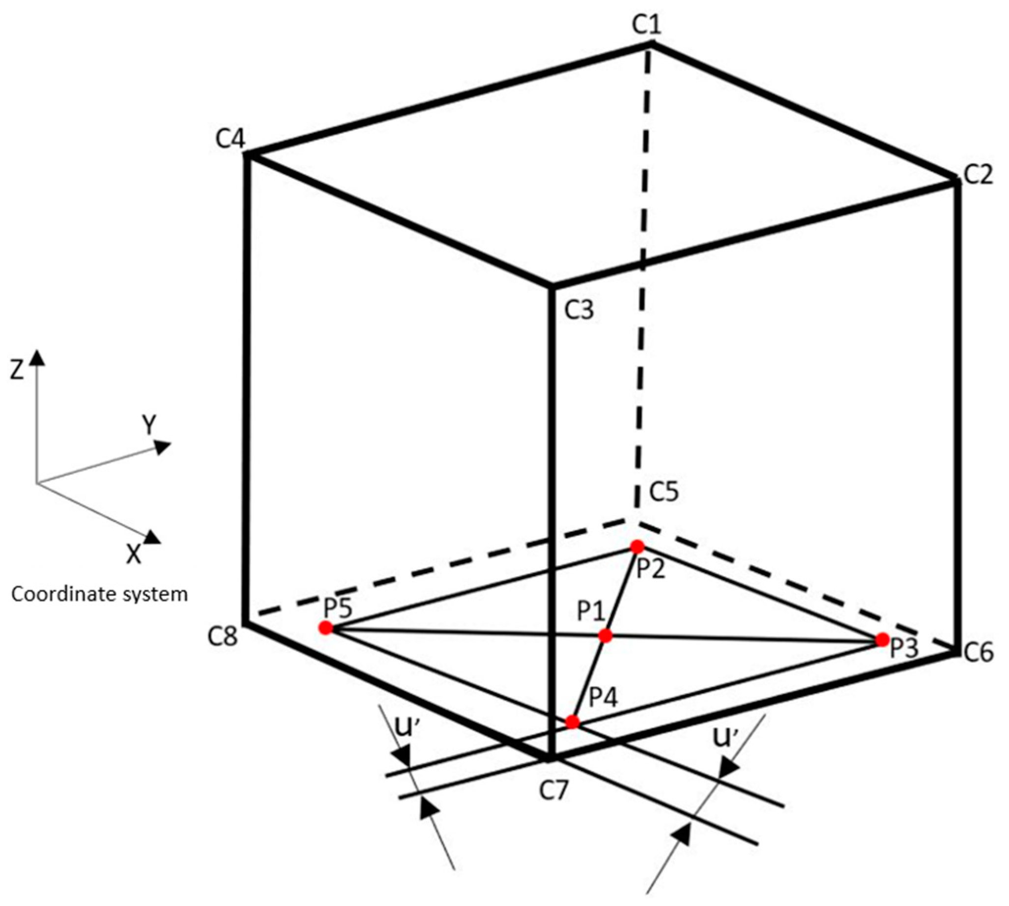
Due to the “touch sensing” function, the Z-axis was omitted from the measurement as the robot can determine the distance from the workpiece in the Z-axis when welding. The proposed ISO cube is displayed in
Figure 6, where the points C5–C6–C7–C8 represented the selected measurement plane and P1 to P5 represented the measured points, respectively.
Commonly used welding speeds range from 30 to 60 m/min, respectively. For this reason, the speed in the measurement was set at 90 m/min, representing 50% of the maximum possible speed. Other test conditions are shown in
Table 2.
5. Creation and Design of a Simulation of a Robotic Welding Workstation
RoboDK software was chosen for the design of the workstation simulation. It is a simulation software that offers an intuitive environment in which various robotic tasks can be programmed, such as welding, palletizing, packaging, milling, 3D printing, etc. In addition, the software supports basic CAD model input formats, such as STEP, IGES, and STL. The advantages of this software compared to other software are as follows [
19]:
An online library containing a large number of robots, positioners, and tools from various manufacturers;
The possibility to insert your own designed robot in the CAD program;
The possibility of testing the precision of robots;
The software runs performance tests according to ISO 9283 (Renishaw ballbar test), and the calibration of robots using laser trackers;
Exporting post processors for the different types of controllers.
This simulation was possible thanks to creating CAD components of the welding station according to the layout of the real workstation. First, the dimensions of the workstation, the positioner, the welding table, and the robot travel were measured. The individual functional units of the equipment are shown in
Figure 7.
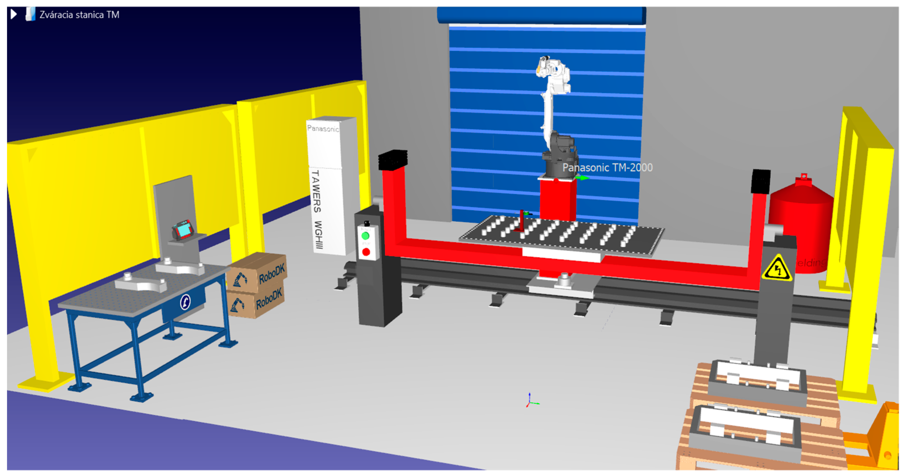
After measuring the main components, it was necessary to determine the layout of the components in the space. After obtaining the dimensions, the individual parts of the station were processed into CAD models using Creo Parametric software. The basic step in creating the station was the insertion and appropriate positioning of the 4500 × 3000 mm floor, which was available from the online library. The next step was inserting the pre-prepared CAD models of the workstation and their layout. In order to insert the files into the software environment, it was necessary to save the components in STEP format, which RoboDK supports. First, barriers with a back wall were added to form the boundary of the workstation. This was followed by inserting the welding station’s most important parts: the positioner, and the vehicle with the base. The Panasonic TM-2000 robot was downloaded from the online library and added to the assembly, where it was placed onto the base with the traveler. Other components added to complete the welding station were a welding table, pallet truck, control box, welding wire, positioner switch, teach pendant, guard markings, and weld parts. The complete design can be seen in the RoboDK software simulation environment, which was as shown in
Figure 8.
Programming and Adding Targets for the Robot
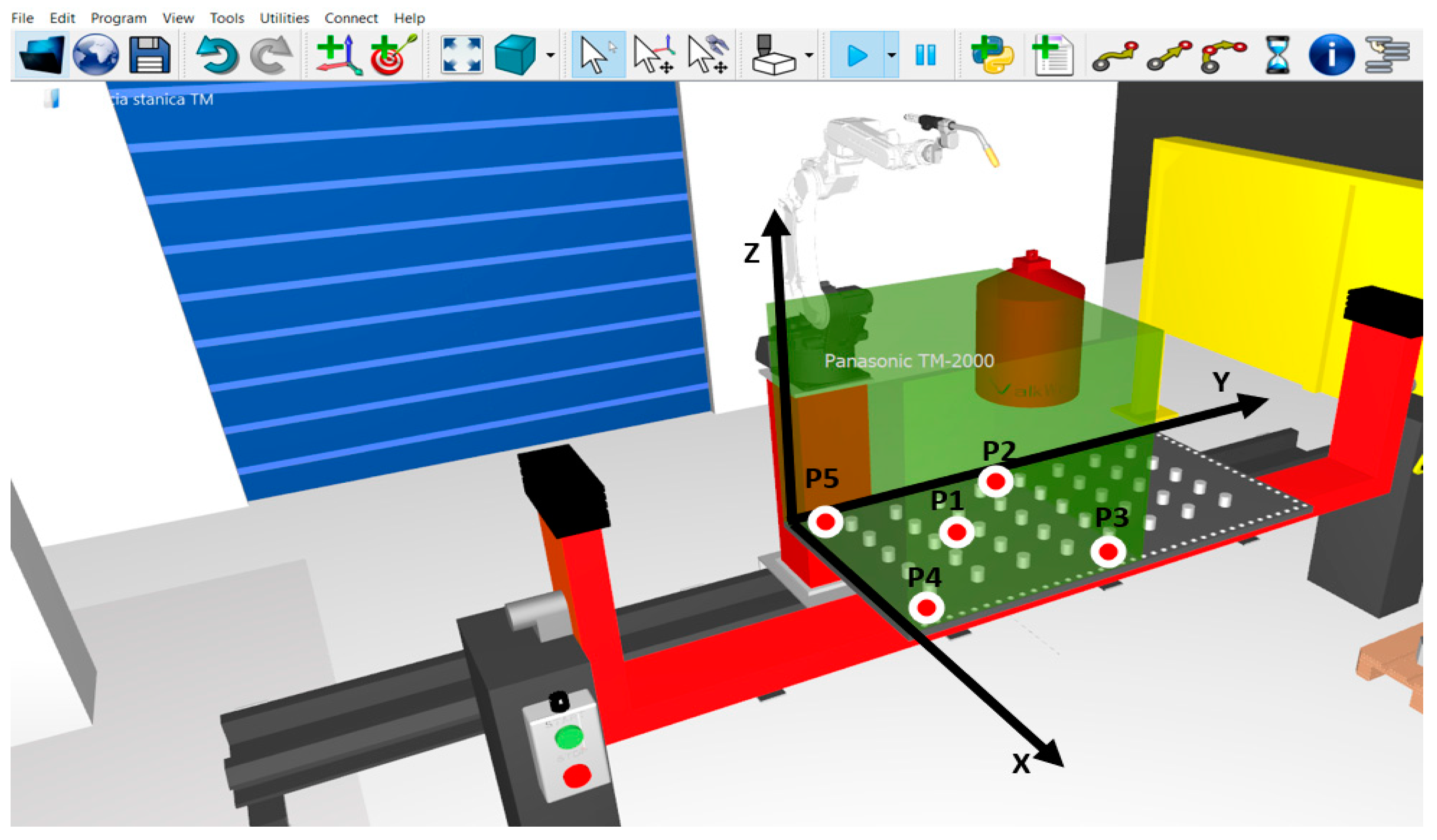
After creating the simulation model of the welding station, the robot motion sequences simulated for the measurement were created. Next, the designed ISO cube with an edge length of 1200 mm was inserted into the robot workspace, which is shown in
Figure 9. The cube was inserted at the place where the robot welds most frequently, which was one of the conditions for measuring the repeatability and positioning accuracy of the robot arm.
Programming the robot motion sequences in RoboDK and thus preparing the measurement program consists of assigning the targets to be reached by the robot. In this case, the targets for the robot were added using the “Teach target(s) on surface” function, located in the “Program” table. By selecting this function, the TCP robot moved in parallel with the selected target by fixing it to a well-defined point on the surface of the inserted cube. In this case, it was the contact area where the contact of the deflector with the welding head occurs. Since the digital indicator has a measuring range of 25.4 mm, the robot needed to compress the contact by 10 mm. After creating all the targets for the robot, the next step was to add and generate the program. In this case, two programs were created, one for the X-axis and one for the Y-axis, respectively, for better transparency.
6. Measurement and Evaluation of Results
During the measurements, it was necessary to observe further rules, which are set out in ISO 9283, such as:
The robot must be mounted under the manufacturer’s control and fully functional during the measurement;
The ambient temperature must be in the range 20–22 °C;
Both the robot and the measuring device must be in a thermally stable condition, and must not be affected by scientific influences, e.g., sunlight;
Before measuring the selected characteristic, the robot must undergo a warm-up cycle, including the drift measurement.
As it was necessary to observe the warm-up cycle, the measurements were made after an 8 h working shift under optimal working conditions: pressure 101.3 kPa, temperature 21 °C, and humidity 38%. After this time, the robot was sufficiently warmed up and ready for measurement. The digital aberration meter was placed in the robot area a day before the measurements were taken to ensure temperature stability.
The actual measurement was preceded by placing the deflection meter on the welding plate. The next step was to run the program on the robot in the so-called test mode, in which the speed was significantly reduced. This mode was used for every newly created program to assess the control program’s correctness.
The robot arm position repeatability was measured after testing the program in the test mode. First, the digital indicator was fixed to the desired position. Next, a cable for data transmission was connected to the digital indicator and a notebook with a blank MS Excel workbook, where the measured values were automatically saved. At the first occurrence of a touch on the digital indicator, the digital indicator was reset at all measurement points so that the reading could be taken directly from the selected point. When the robot entered the programmed position, a 5 s pause allowed the value on the deflector to settle, and then the value was written to the PC by pressing a button on the cable.
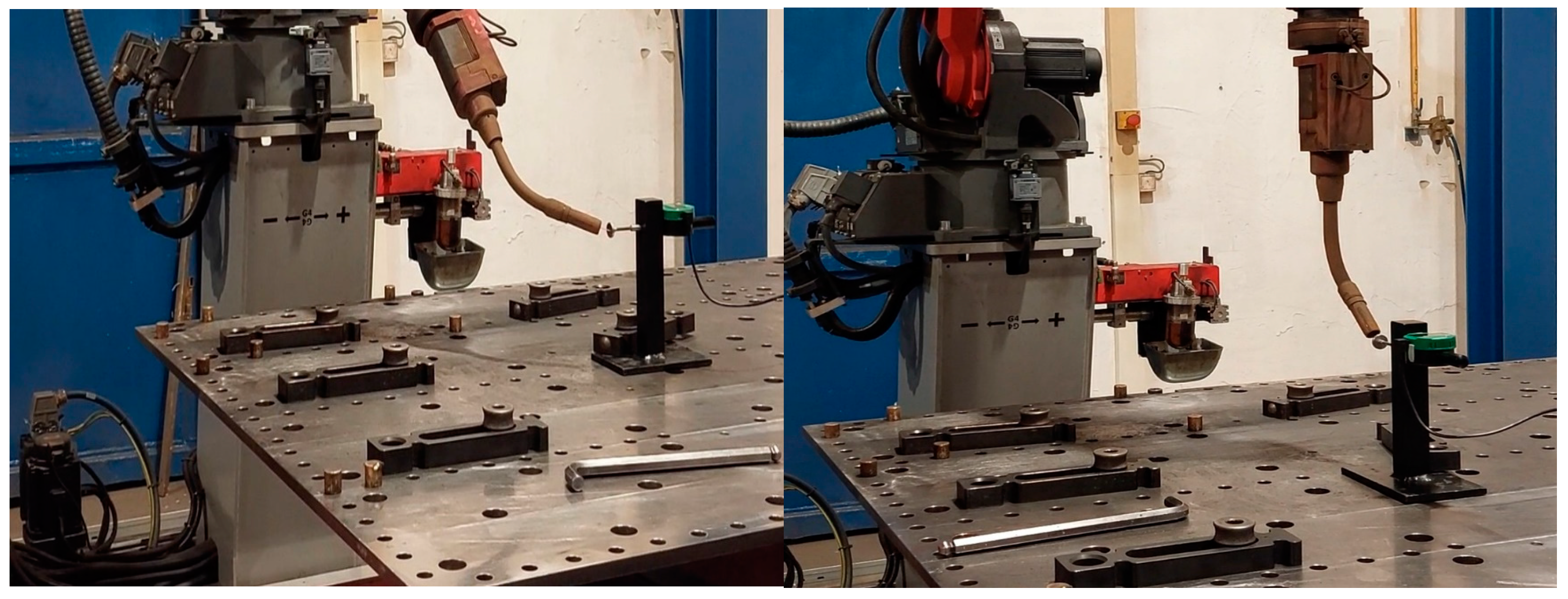
Figure 10 shows the aberration meter at the measured point P1 on the X-axis and Y-axis.
The X-axis was measured first, and the measurement started at P1. After 30 readings were recorded for point P1, the program was paused, and the jig with the digital indicator was moved to position P2. The measurement continued similarly at points P3, P4, and P5.
Table 3 shows the measured X-axis deviation values.
The measurement continued with the control program for the Y-axis, where the jig with the deflection gauge was rotated by 90° and set to position P1. On the first touch, the digital indicator was reset, and then on the next 30 touches, the values were recorded. As with the X-axis point measurements, the measuring device was moved to the remaining positions (P2, P3, P4, and P5) where 30 values were recorded for each point, as summarized in
Table 4.
7. Discussion
A total of 300 measurements were obtained, followed with a repeatability count. The repeatability was calculated for each measurement point separately. From the measured values, it was impossible to calculate the average one-way repeatability of the position as the equipment was moved when measuring the deviations of one point. Since the measurement was made in the X and Y axes, the axes were measured separately.
In particular, using the formula to calculate the total unidirectional position repeatability as specified in the standard was not possible. For this reason, an equation based on the standard deviation (Equation (5)), where the index
pn denotes the point to be measured, was used to calculate the repeatability.
Subsequently, the results obtained from the calculation were compared with the data reported by the manufacturer, which are presented in
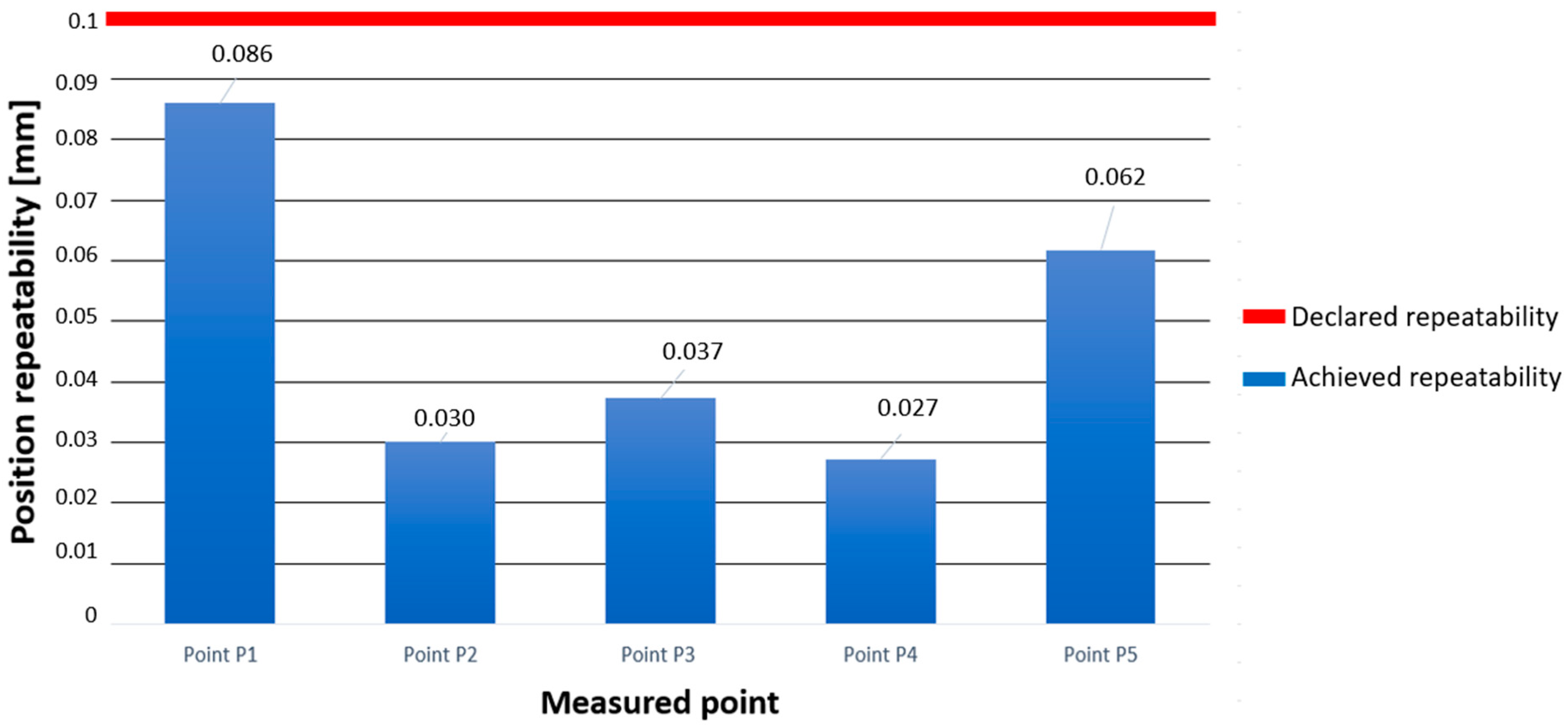
Table 5. The measurement results for the X-axis clearly show that the robot achieved an even better repeating in the X-axis than that given by the manufacturer. Furthermore, comparing the results from the Y-axis measurement with the value given by the manufacturer also showed that the robot achieved a better repeatability.
It was also possible to examine the graphical processing of the calculated standard deviations for the points on the X-axis, as shown in
Figure 11.
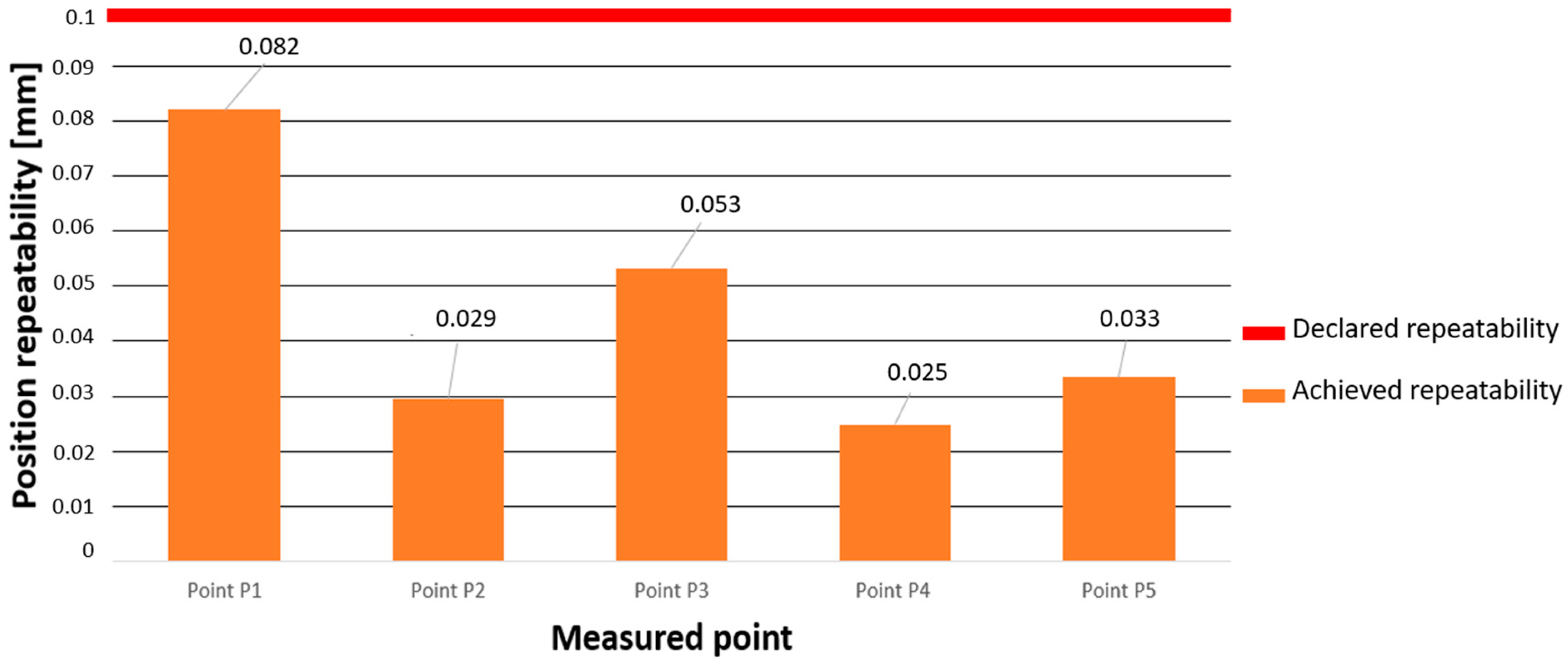
The graph for the Y-axis was also processed in the same way, as shown in
Figure 12.
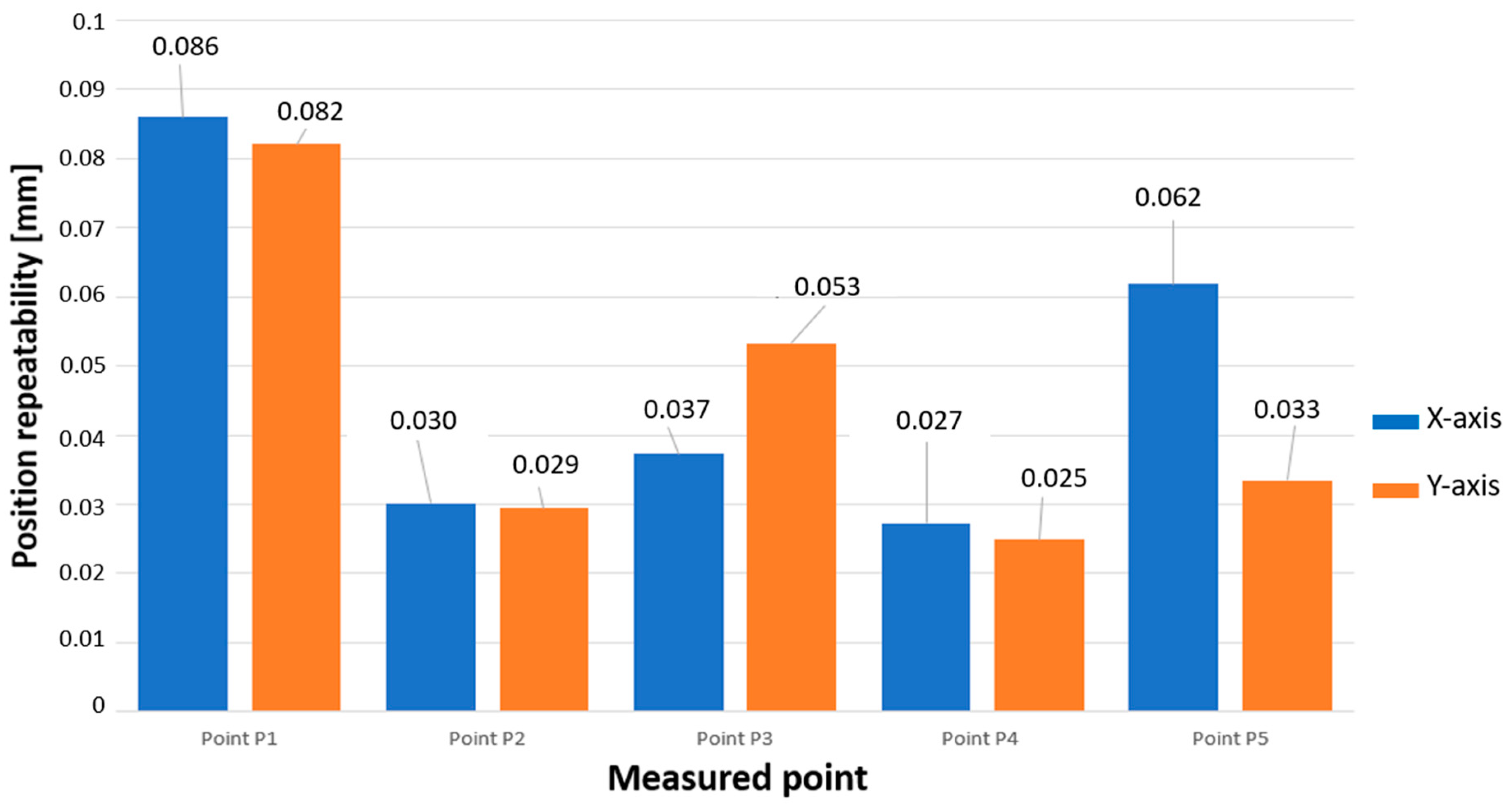
From graphically comparing the achieved values in the X and Y axes, it is shown in in
Figure 13 how the robot achieved an almost identical repeatability values at points P1, P2, and P4. The assumption was that at points P3 and P4, which were at the boundary of the working space and thus when the robot’s arm was the most extended, it would achieve the worst repeatability, but this assumption was not confirmed. The worst repeatability for both measurements was achieved at point P1, which was located in the middle of the designed measurement plane.
The specific result we obtained was that the robot achieved a better repeatability at each point than the manufacturer indicated. However, the measured values at point P1 indicated that the repeatability around the measured point may deteriorate.
8. Conclusions
The ISO 9283 standard forms the basis for assessing the performance characteristics of industrial robots. The unidirectional position repeatability is one of the most important parameters to be monitored regarding the reported accuracy of robots. Most manufacturers declare the repeatability and position accuracy based on tests they performed according to the ISO 9283 standard. However, in the case of Panasonic, it could not be clearly established on how and on what basis the manufacturer tests its industrial robots. The following factors contribute to the deterioration of position repeatability: irregular calibration of the robot axes, arm overstressing, or collisions after which the robot has not been calibrated and inspected.
The object of study described in the paper was a Panasonic TM-2000 welding robot, which welds the end frames for forklift trucks in the factory. This paper discussed the selection of a suitable metrological device for a quick repeatability check and a possible calibration of the robot directly at the workplace, with an emphasis on the simplicity and efficiency of the device’s measurement for workers working at a welding robotic workplace. The RoboDK software was chosen for the simulation design of the trajectories and the generation of the control program for the realization of the robot repeatability measurements. The measurements and the simulations were possible thanks to designing and manufacturing a measuring device, an imaginary ISO cube, a measuring plane, measuring points, and a cycle to determine in which order the points would be measured. This paper further described the design procedure of the ISO cube, which formed the basis for the design of the measurement plane and the measurement points. A digital indicator was chosen as the measuring device on which a flat touch was used. The disadvantage of the digital indicator is the impossibility of measuring in the Z-axis, but in this case, the measurement was made in the X and Y axes. As the robot included a touch sensing function, it was not necessary to perform measurements in the Z-axis as specified by the ISO 9283 standard as the robot verified the position of the welding nozzle through an integrated sensor during calibration before starting the welding process.
The analytical part resulted in a direct measurement of the position repeatability on the welding robot. A total of five points were measured for the X-axis and five points for the Y-axis, respectively. Each point was recorded 30 times, and the measurements were taken in the positive direction of motion. These results were compared with the value provided by the manufacturer, and the measured deviations were also processed graphically. The robot achieved better results compared the manufacturer’s results at each point. After comparing the results in both axes, the trend in that the more the robot’s arm is stretched, the worse the repeating the robot achieves, was not confirmed. The assumption we made was that at point P1, where the robot has achieved the worst repeatability, the repeatability and accuracy may deteriorate in the future.
After consulting the results with the quality department of the manufacturing company, the following recommendations were proposed for maintaining the quality and repeatability of the robot:
Regularly perform calibration of all robot axes and also their positioners;
Regularly check the shape of the welding torch and correct any irregularities;
Using the designed measuring device to check the repeatability of the robot on the trajectories of the busiest workplace points;
In the event of a robot collision, perform calibration, and then check the repeatability with the designed measuring device.
Author Contributions
Conceptualization, K.G. and M.P.; methodology, M.P.; software, K.G.; validation, M.P.; formal analysis, K.G. and M.P.; investigation, M.P.; resources, K.G.; data curation, K.G.; writing—original draft preparation, K.G. and M.P.; writing—review and editing, M.P.; visualization, K.G.; supervision, M.P.; project administration, M.P. All authors have read and agreed to the published version of the manuscript.
Funding
This research received no external funding.
Data Availability Statement
Not applicable.
Acknowledgments
The authors thank the Ministry of education of Slovak Republic for supporting this research by the grant VEGA no. 1/0121/23, KEGA no. 038TUKE-4/2021, project APVV-18-0316 and APVV-19-0550.
Conflicts of Interest
The authors declare no conflict of interest.
References
- Muelaner, J.E.; Wang, Z.; Maropoulos, P.G. Concepts for and Analysis of a High Accuracy and High Capacity (HAHC) Aerospace Robot. Proc. Inst. Mech. Eng. 2011, 225, 1393–1399. [Google Scholar] [CrossRef]
- Niku, S.B. Introduction to Robotics: Analysis, Control, Applications, 3rd ed.; Standards Information Network: Chichester, UK, 2019; ISBN 9781119527602. [Google Scholar]
- Placyek, M.; Pisycyek, L. Testing of an Industrial Robot’s Accuracy and Repeatability in Off and Online Environment. Eksploat Niezawodn-Maint. Reliab. 2018, 20, 455–464. [Google Scholar] [CrossRef]
- Broum, T.; Simon, M. Safety Requirements Related to Collaborative Robots in the Czech Republic. MM Sci. J. 2020, 1, 3852–3856. [Google Scholar] [CrossRef]
- Hu, M.; Wang, H.; Pan, X.; Tian, Y. Optimal Synthesis of Pose Repeatability for Collaborative Robots Based on the ISO 9283 Standard. Ind. Rob. 2019, 46, 812–818. [Google Scholar] [CrossRef]
- Motta, J.M.; Carvalho, G.C.; McMaster, R.S. Robot Calibration Using a 3D Vision-Based Measurement System with a Single Camera. Robot. Comput. Integr. Manuf. 2001, 17, 487–497. [Google Scholar] [CrossRef]
- Ondocko, S.; Svetlik, J.; Sasala, M.; Bobovsky, Z.; Stejskal, T.; Dobransky, J.; Demec, P.; Hrivniak, L. Inverse Kinematics Data Adaptation to Non-standard Modular Robotic Arm Consisting of Unique Rotational Modules. Appl. Sci. 2021, 11, 1203. [Google Scholar] [CrossRef]
- Zaborowski, T.; Panda, A.; Androvic, L. Robots and Cobots, Main Differences. Stud. Mater. 2019, 39, 4–8. [Google Scholar]
- Landstorfer, P.; Hiller, J.; Herbst, M. Investigation of Positioning Accuracy of Industrial Robots for Robotic Based X-ray Computer Tomography. In Proceedings of the 9th Conference on Industrial Computed Tomography, (iCT 2019), Padova, Italy, 13–15 February 2019; pp. 1–5. [Google Scholar] [CrossRef]
- Stejskal, T.; Svetlik, J.; Ondocko, S. Mapping Robot Singularities through the Monte Carlo Method. Appl. Sci. 2022, 12, 8330. [Google Scholar] [CrossRef]
- Gharaaty, S.; Shu, T.; Joubair, A.; Xie, W.F.; Bonev, I.A. Online Pose Correction of an Industrial Robot Using an Optical Coordinate Measure Machine System. Int. J. Adv. Robot. Syst. 2018, 15, 1729881418787915. [Google Scholar] [CrossRef] [Green Version]
- Nubiola, A.; Slamani, M.; Joubair, A.; Bonev, I.A. Comparison of Two Calibration Methods for a Small Industrial Robot Based on an Optical CMM and a Laser Tracker. Robotica 2014, 32, 447–466. [Google Scholar] [CrossRef]
- Slamani, M.; Nubiola, A.; Bonev, I. Assessment of the Positioning Performance of an Industrial Robot. Ind. Robot. 2012, 39, 57–68. [Google Scholar] [CrossRef]
- Józwik, J.; Ostrowski, D.; Jarosz, P.; Mika, D. Industrial Robot Repeatability Testing with High Speed Camera Phantom V2511. Adv. Sci. Technol. Res. J. 2016, 10, 86–96. [Google Scholar] [CrossRef] [Green Version]
- Vocetka, M.; Bobovský, Z.; Babjak, J.; Suder, J.; Grushko, S.; Mlotek, J.; Krys, V.; Hagara, M. Influence of Drift on Robot Repeatability and Its Compensation. Appl. Sci. 2021, 11, 10813. [Google Scholar] [CrossRef]
- ISO 9283:1998; Manipulating Industrial Robots—Performance Criteria and Related Test Methods. ISO: Geneva, Switzerland, 1998.
- Józwik, J.; Jacniacka, E.; Ostrowski, D. Uncertainty Measurement with the Kinematic Telescopic Bar during Industrial Robot Inaccuracy Tests. ITM Web Conf. 2017, 15, 04013. [Google Scholar] [CrossRef] [Green Version]
- Kuric, I.; Tlach, V.; Ságová, Z.; Císar, M.; Gritsuk, I. Measurement of Industrial Robot Pose Repeatability. MATEC Web Conf. 2018, 244, 01015. [Google Scholar] [CrossRef] [Green Version]
- Simulator for Industrial Robots and Offline Programming—RoboDK. Available online: https://robodk.com/ (accessed on 29 May 2023).
| Disclaimer/Publisher’s Note: The statements, opinions and data contained in all publications are solely those of the individual author(s) and contributor(s) and not of MDPI and/or the editor(s). MDPI and/or the editor(s) disclaim responsibility for any injury to people or property resulting from any ideas, methods, instructions or products referred to in the content. |
© 2023 by the authors. Licensee MDPI, Basel, Switzerland. This article is an open access article distributed under the terms and conditions of the Creative Commons Attribution (CC BY) license (https://creativecommons.org/licenses/by/4.0/).


