Article

Hybrid 3D Printing of Functional Smart Hinges

Department of Mechanical Engineering, University of Nevada Reno, Reno, NV 89557, USA
*
Author to whom correspondence should be addressed.
Machines 2023, 11(7), 686; https://doi.org/10.3390/machines11070686
Submission received: 30 May 2023 / Revised: 18 June 2023 / Accepted: 21 June 2023 / Published: 29 June 2023
(This article belongs to the Special Issue Fundamentals and Applications of 3D Printing for Novel Materials)

Abstract

:
Smart hinges fabricated using three-dimensional (3D) printing have been accepted in the aerospace, robotics, and biomedical fields since these devices possess a shape memory characteristic. Shape memory polymers (SMPs) are the preferred materials for creating smart hinges due to their ability to achieve programmable complex geometries. However, fabricating SMPs with embedded components remains a challenge due to the constraints of current 3D printing methods and material limitations. This study investigated the use of a hybrid 3D printing method, direct ink writing (DIW), and embedded 3D printing (e-3DP) to print smart hinges with an embedded circuit to act as a strain sensor. The main components of the SMP included tert-Butyl acrylate (tBA) and aliphatic urethane diacrylate (AUD), but this SMP ink had a low viscosity and could not be used for DIW or e-3DP. Fumed silica (FS) was added to the SMP to tune its rheology, and it was shown that the FS concentration significantly affected the rheological properties, dry-out process, filament geometries, and self-supporting capabilities. This study presents a hybrid 3D printing approach for creating smart hinges with internal strain sensors in one step, demonstrating the versatility of DIW/e-3DP. The findings from this work provide a foundational and reliable technical solution to efficiently fabricate functional, self-monitoring, smart devices from SMPs for diverse applications.

1. Introduction

Functional smart hinges are a category of mechanical actuators commonly made from programmable materials, such as shape memory polymers (SMPs) and shape memory alloys (SMAs) [1,2]. Smart hinges can be deformed into pre-defined shapes through a programming process but can subsequently return to their original shapes upon the application of external stimuli [1,2,3,4]. In comparison to SMAs, SMPs present many unique merits, including better shape recoverability [5], tunable mechanical properties [5], lightweight [6], affordability [7], and good manufacturability [8]. In addition, a wider range of external stimuli, such as electricity, light, magnetic fields, chemicals, and water content, can be utilized to induce shape change in smart hinges made from SMPs [5,9,10]. Due to these appealing properties, SMP hinges have been widely used in aerospace [11,12,13], soft robotics [14,15], and biomedical fields [16,17].
The fabrication of SMP hinges is highly dependent on the manufacturing techniques that can be used. Currently, SMP hinges are primarily fabricated via two strategies: (1) casting [18,19] and (2) three-dimensional (3D) printing. In casting, a curable matrix solution is poured into a mold with given geometries, and after crosslinking, the solid matrix is removed from the mold and used as the hinge. While casting is a convenient way to make SMP hinges, the demolding requirement constrains the complexity of a mold, directly limiting the geometries of achievable hinges. It also remains challenging to cast multiple SMPs with different geometries simultaneously in one mold, hindering the fabrication of smart hinges with internal components such as sensors.
The development of 3D printing technology provides an attractive solution for producing SMP hinges with complex geometries. The predominantly used methods include two categories of printing strategies: (1) vat photopolymerization and (2) material extrusion. In vat photopolymerization, a photocurable resin is held in a container and each layer is selectively crosslinked by light radiation to construct a 3D structure [20,21]. Although vat photopolymerization has a relatively high fabrication efficiency, it cannot be used to fabricate heterogeneous structures and requires build material to have a low viscosity and be photocrosslinkable [18,19], severely limiting the selection of SMPs.
Material extrusion is currently the most popular 3D printing method because of its wide range of printable materials, the capability of printing multiple materials in a 3D structure, and the acceptable mechanical properties of printed parts [6,22,23,24,25]. In material extrusion, liquid build material is extruded through a dispensing nozzle to form continuous filaments that are stacked and solidified layer-by-layer to construct a 3D structure [26]. Direct ink writing (DIW) and embedded 3D printing (e-3DP) are two sub-techniques of material extrusion. DIW has been widely used to print complex architectures in air [27,28,29] while e-3DP is known for creating embedded functional components within a matrix or support bath [30,31,32]. DIW has been used to fabricate SMPs. For example, Kuang et al. printed a highly stretchable shape memory elastomer to make smart devices for the robotics and biomedical fields [33]. In their work, the low viscosity ink was cured after each layer was completed, but the method did not incorporate any internal features and was not capable of constructing 3D sensors. Chen et al. developed an epoxy-based SMP ink for DIW that could support itself with the aid of nanoparticles such as FS, but their method was not capable of printing any internal components from different materials at the same time [34]. Heterogeneous, functional smart hinges have not been printed via DIW. While the printing of conductive features in elastomers using e-3DP has been demonstrated [35,36], the successful integration of e-3DP conductive sensors in SMPs has not been achieved yet. Since a functional hinge encompasses not only the hinge body but also diverse auxiliary components such as sensors and stimulus inducers, current material extrusion methods are unable to print these components simultaneously. Combining DIW and e-3DP is a promising solution for fabricating heterogenous SMPs with internal features.
In this work, a hybrid DIW/e-3DP approach was proposed, in which e-3DP deposited a conductive ink, carbon conductive grease, in a desired pattern within a liquid SMP hinge printed by DIW. A photocurable and thermosensitive shape memory resin [12], mainly composed of tert-Butyl acrylate (tBA) and aliphatic urethane diacrylate (AUD), was selected as the SMP base. Fumed silica (FS), a commonly used rheological modifier [27,32,37,38,39,40], was mixed with the SMP to enable the ink to have a self-supporting property in a liquid state [37,38]. After printing, ultra-violet (UV) radiation was employed to crosslink the hinge structure and enclose the conductive ink pattern that serves as a sensor in the hinge. The deformation of the hinge was controlled through programming at higher temperatures and remained at the programmed shape after the temperature was removed. Once the ambient temperature increased to a given range, the hinge recovered its original shape and functioned as an actuator. During this process, the sensor detected the resistance change, thus quantifying the deformation history. This proposed approach offered a feasible solution to print SMP hinges with embedded sensors in a single step, significantly improving fabrication efficiency.

2. Materials and Methods

2.1. Material Preparation

The SMP ink consisted of a photocurable resin and a yield–stress additive. Specifically, the resin chosen in this work included four main components [12]: (1) tert-Butyl acrylate (tBA), which was the linear chain builder, (2) aliphatic urethane diacrylate (AUD), which was the crosslinker, (3) isobornyl acrylate (IBOA), which was used to dilute AUD, and (4) diphenyl(2,4,6-trimethylbenzoly)phosphine oxide (TPO), which was the photoinitiator. The SMP ink of tBA/AUD has been developed and used in recent years because of its higher stiffness, good deformability, excellent fatigue resistance, and UV crosslinkability, but only vat photopolymerization methods have been used to make 3D parts from tBA/AUD [12,36]. The addition of FS changes the rheological properties and enables the ink to have a self-supporting capability.
During SMP ink preparation, an AUD/IBOA mixture was prepared first by mixing AUD (Ebecryl 8413, Allnex Inc. Alpharetta, GA, USA) and IBOA (Sigma-Aldrich, St. Louis, MO, USA) solutions at the volume ratio of 67:33 using a glass rod until the mixture was homogenous. Then, the appropriate amount of tBA (Sigma-Aldrich, St. Louis, MO, USA) was added to the AUD/IBOA mixture and stirred manually until it was homogenous. The tBA/AUD ratio was 50/50. After that, TPO (Sigma-Aldrich, St. Louis, MO, USA) was added at a concentration of 2.0% (w/v) and mixed using a magnetic stirrer (5-inch, Four E’s Scientific, West Windsor, NJ, USA) at 1000 rpm until the mixture was homogenous. Finally, FS (Aerosil@R812S, Evonik, Parsippany, NJ, USA) powder was dispersed in the mixture at different concentrations and stirred uniformly using a glass rod for 20 min. Following that, the ink was perfused into a syringe barrel (10 cc, Optimum® syringe barrels, Nordson EFD, East Providence, RI, USA) and degassed in a centrifuge (PowerSpinTM Series, Cole-Parmer, Vernon Hills, IL, USA) at 2500 rpm for 2 min to remove air bubbles. All preparation steps were performed at room temperature (24 °C). To investigate the effects of FS concentrations on key rheological properties, dry-out phenomenon, filament geometries, and self-supporting capabilities, SMP inks with 6%, 8%, and 10% (w/v) FS were prepared.
When the e-3DP of the sensor was prepared, the conductive ink (8481 Premium Carbon Conductive Grease, MG Chemicals, Burlington, ON, Canada) was directly perfused into a syringe barrel at room temperature. The conductive ink was then degassed in the centrifuge at 2500 rpm for 2 min to remove entrapped air bubbles.

2.2. SMP Ink Characterization

The rheological properties of the SMP inks with different FS concentrations directly determined the SMP inks’ suitability for extrusion-based 3D printing, as both a self-supporting ink and a matrix bath. The rheological tests were performed using a rheometer (MCR 92, Anton Paar, Graz, Austria) equipped with a 50 mm diameter cone/plate measuring tool with a cone angle of 1° and a cone-to-plate gap distance of 0.102 mm. Steady shear rate sweeps were conducted at room temperature to determine the yield stress of each SMP ink, where the inks were sheared at a shear rate varying from 0.01 to 1000 s−1 and the shear stress during shearing was recorded. Transient step shear rate sweeps were performed at room temperature to evaluate the thixotropic response time of each SMP ink. The SMP ink was first pre-sheared at a relatively high shear rate of 10 s−1 for 120 s and then sheared at a low shear rate of 0.01 s−1. The viscosity change at the low shear rate was recorded for 200 s to quantify the transition of each SMP ink from a liquid to a solid-like state.
To investigate the dry-out phenomenon, SMP inks with different FS concentrations were added into the custom-made molds (25.4 mm × 25.4 mm × 1 mm). The initial mass of each mold with the ink (i.e., a specimen) was measured using an analytic balance (Pioneer PX5, Ohaus Corporation, Parsippany, NJ, USA) as w0. Following that, the mass of each specimen (wi) was measured every 10 min for 90 min in total. In this process, the ink was not removed from the mold. The mass loss was computed by: Mass loss percentage = (w0wi)/w0 × 100%. The SMP ink with 0% FS was prepared and measured per the same protocol for comparison. All measurements were carried out at room temperature.

2.3. Printing System and Filament Printing Protocol

A 3D bioprinter (Starter series, EnvisionTEC, Dearborn, MI, USA) was used to deposit SMP ink with different FS concentrations into C-shaped 2D patterns on plastic Petri dishes (AP8170 (Φ60 mm × 15 mm), Flinn Scientific, Batavia, IL, USA). The filament width and corner distance in DIW and filament width in e-3DP were measured using a high-precision measurement system (Vertex 251UC, MicroVu, Windsor, CA, USA). To investigate the effects of path speed and pressure on filament width in DIW, a 25-gauge (G) dispensing nozzle (Dispense All, Chicago, IL, USA) with an inner diameter of 0.28 mm was used to print the C-shaped 2D patterns. The path speed was increased from 0.5 to 3.5 mm/s in increments of 0.5 mm/s at a constant pressure of 2.5 bar (2.5 × 10⁵ Pa). The pressure was increased from 1.5 to 2.5 and 3.5 bar while maintaining a constant path speed of 1.5 mm/s. To study the effects of path speed and pressure on shape fidelity, the distance between the designed path and the printed pattern at one corner was defined as corner distance, which was used to quantify the shape fidelity [28]. Herein, the path speed increased from 1.5 to 4.5 mm/s at intervals of 0.5 mm/s at a constant pressure of 2.5 bar. The pressure was increased from 1.5 to 2.5 and 3.5 bar while maintaining a constant path speed of 1.5 mm/s.
The effects of path speed and pressure on the filament width of the conductive ink during e-3DP were also characterized. The conductive ink was extruded from a 27-G dispensing nozzle (Dispense All, Chicago, IL, USA) to print 2D-shaped within the SMP ink matrix. The path speed increased from 0.1 to 1.0 mm/s in increments of 0.1 mm/s while the pressure remained at 2.5 bar. The pressure was then increased from 2.5 bar to 4.5 bar in increments of 0.5 bar while the path speed was held constant at 0.3 mm/s. Since the conductive ink was deposited and held in situ in the SMP, corner distance was not investigated.

2.4. Characterization of Self-Supporting Capability

To demonstrate the self-supporting capability of the SMP inks, vertical tubes with a diameter of 10 mm and a height of 10 mm were printed using a 25-G dispensing nozzle at a path speed of 1.5 mm/s and a dispensing pressure of 2.5 bar. Following the printing process, images of each tube were captured using a digital camera (DC-FZ80, Panasonic, Osaka, Japan). These images were then analyzed using the software ImageJ (available at https://imagej.nih.gov/ij/, accessed on 2 March 2022) to obtain precise measurements of the actual diameter and height of the tubes. To investigate the deflection when printing spanning features, a custom-made supporting tool fabricated in the lab featured gap distances of 0.5, 1.0, 2.0, 4.0, 6.0, 8.0, and 10.0 mm [28]. Filament beams composed of SMP inks with different FS concentrations were extruded through the 25-G dispensing nozzle and deposited onto the supporting tool. The same printing parameters as the tube printing were used. The digital camera was used to capture images of the filament beam deflections at the largest gap distance of 10.0 mm and the deflections were measured using ImageJ 1.53n 7.

2.5. Hinge 3D Printing, Characterization, and Application

A hinge structure was designed using SolidWorks 2022 (Dassault Systems SolidWorks Corp., Waltham, MA, USA). The 3D model file was loaded into the software of the 3D printer (Perfactory RP, EnvisionTEC GmbH, Gladbeck, Germany) for slicing before printing. A 25-G nozzle was used to print the hinge body at a path speed of 1.5 mm/s and a dispensing pressure of 2.5 bar. The step distance, namely, the height between layers, was set at 400 μm so the new layer can be fully in contact with the previous layer. To create the conductive ink pattern within the liquid hinge structure, a 27-G dispensing nozzle was utilized. The conductive ink was heated to 37 °C using the temperature control on the 3D printer and then deposited in a square-wave pattern within the top of the hinge. The path speed was set at 0.3 mm/s and the pressure was held at 3.5 bar.
Following the printing process, a copper wire (32 AWG Enameled Copper Wire, BNTECHGO, Shenzhen, China) was inserted into the ends of the embedded sensor and a UV curing system (OmniCube Series 2000, wavelength: 320–500 nm, Lumen Dynamics, Mississauga, ON, Canada) was positioned 30 mm above the hinge structure for crosslinking. The total UV radiation lasted 100 s, where 50 s allocated for both the top and bottom sides of the hinge. Both the printing and crosslinking processes were conducted at room temperature. After crosslinking, a heating wire (Nichrome 80 Wire, Master Wire Supply, Beavercreek, OH, USA) was woven through the slots of the hinge. To program the hinge, the temperature of the heating wire was increased to 130 °C via Joule heating where a power supply (HY3005F-3, Dr.meter, Shenzhen, China) was set to 2.2 amps and 7.5 volts. A digital thermometer (2 channels K-type thermometer, Gain Express, Hong Kong, China) was used to measure the temperature of the heating wire and smart hinges. The hinge was manually folded during this process and remained in this folded state for 1 min after the power supply was powered off and the hinge gradually decreased back to room temperature, completing the programming step. To initiate shape recovery, the temperature of the heating wire hinge was increased again to 130 °C by Joule heating. To demonstrate the hinge’s application, two hinges deployed mock solar panels from a mock space shuttle which were both designed using SolidWorks 2022 and printed using polyethylene terephthalate glycol (PETG) (PETG Filament 1.75 mm, Overture 3D, Bluffton, SC, USA) and a 3D printer (SV04, Sovol 3D, Shenzen, China). Herein, hex bolts (M2, McMaster-Carr, Santa Fe Springs, CA, USA) and hex nuts (M2, McMaster-Carr, Santa Fe Springs, CA, USA) were used to fix the hinges to the mock solar panels and the mock space shuttle. The copper wires from one hinge were attached to a voltage divider that used two 270 kΩ resistors (carbon film with 0.032” wire diameter, McMaster-Carr, Santa Fe Springs, CA, USA) and a microcontroller (Arduino Mega 2560 Rev3, Arduino, Somerville, MA, USA) to monitor the changing resistance as the hinge returned from its folded, programmed shape to its original shape. The deployment process was also recorded using the digital camera and the temperature distribution of the hinges was captured using a thermal camera (E54, Teledyne FLIR, Wilsonville, OR, USA).

2.6. Statistical Analysis

In this study, all experiments, including rheological property measurements, mass loss during dry-out, filament printing, and characterization of self-supporting capability, were conducted three times, and the quantitative values presented in the figures were reported as mean, with the error bars indicating the standard deviations.

3. Results

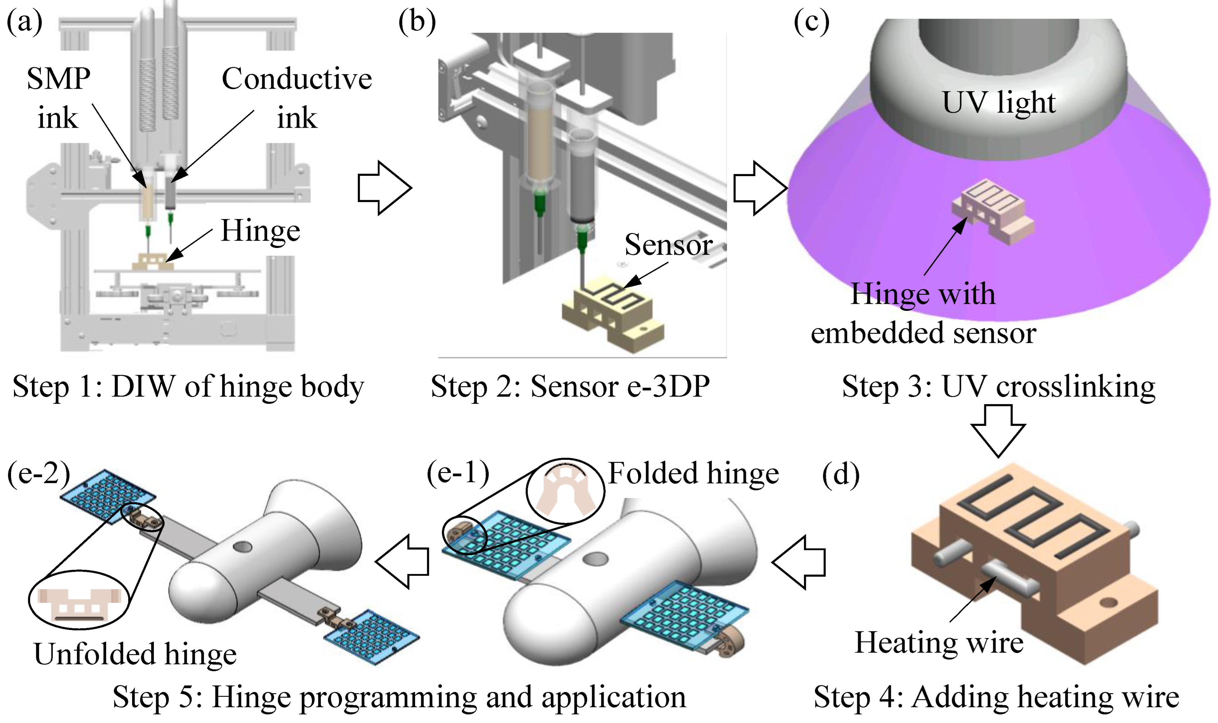
3.1. Mechanism of the Proposed 3D Printing Method

The proposed hybrid DIW/e-3DP method relied on a material-driven approach, as illustrated in Figure 1. The addition of FS particles resulted in the formation of a 3D microstructure [37,38] within the UV-curable resin, enabling the resulting SMP ink to possess the necessary yield–stress characteristic [32,41] for DIW. In material extrusion, the ink travels through the dispensing nozzle and experiences high shear stress that disrupts this microstructure, leading to a reduction in ink viscosity and facilitating the extrusion process. As the ink is extruded from the nozzle, the shear stress decreases below a critical value that is known as the yield stress of the ink. At this point, the disrupted microstructure of the ink quickly regains its stability, resulting in a solid-like behavior at the macroscopic level. This self-supporting capability allows the ink to maintain its shape without external support [41,42]. Consequently, a yield–stress SMP ink was required to print a hinge structure while in an uncrosslinked, liquid state, maintaining its initial shape without undergoing physical or chemical crosslinking, as depicted in Figure 1a.
The yield–stress property of the SMP ink facilitated the subsequent e-3DP step. As illustrated in Figure 1b, when the dispensing nozzle of the conductive ink moved within the printed hinge to deposit the circuit, the nozzle’s movement induced high shear stress that disrupted the 3D interconnected microstructure surrounding the nozzle tip, resulting in a localized transition from solid-like to liquid behavior. The liquefied material enabled free movement of the nozzle and quickly filled the gap behind it, trapping the deposited conductive ink in situ. When the nozzle left that region, the localized shear stress rapidly decreased below the yield stress, the 3D networked microstructure recovered, and the material behaved solid-like again to stably hold the circuit in place.
Following the hybrid 3D printing process, copper wires were attached to the ends of the embedded circuit in the hinge and the entire part was crosslinked by UV radiation. In this crosslinking step, the molecular chains of the photocurable resin were firmly connected by chemical crosslinking [43]. This resulted in the formation of dual 3D networked microstructures: one was made by FS particles and the other was built by resin polymer chains. As a result, the hinge possessed sufficient mechanical stiffness to function as an authentic actuator. Finally, the integration of the heating wire (Figure 1d) with the hinge facilitated its deformation in response to an increase in temperature, as illustrated in Figure 1(e-1,e-2).

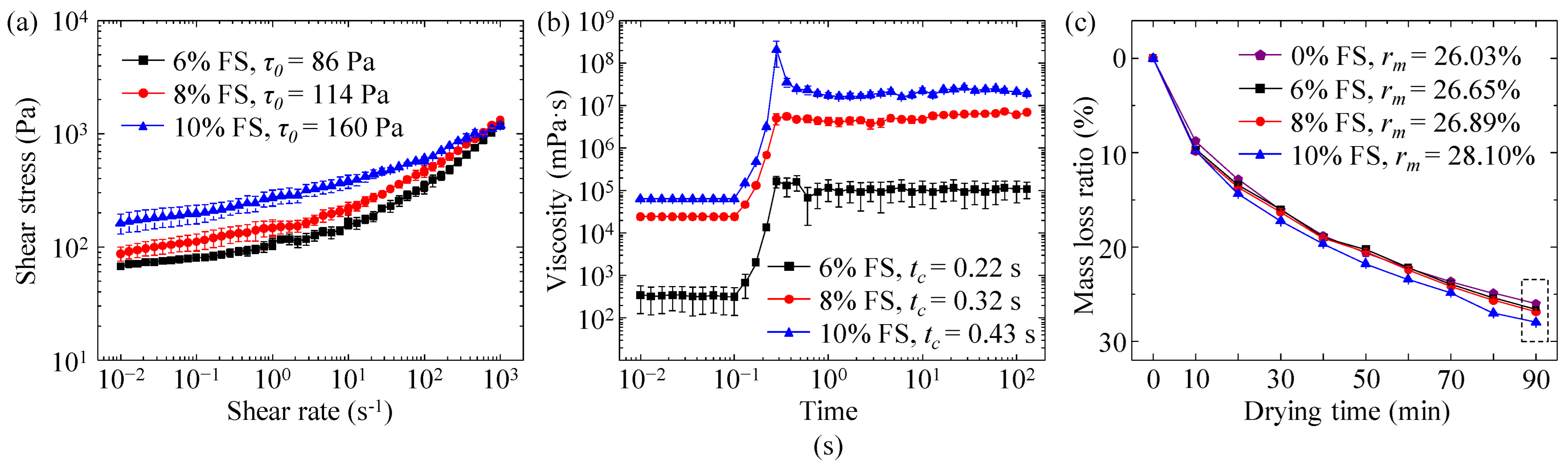
3.2. Effects of FS Concentrations on the Rheological and Dry-Out Properties of SMP Inks

The rheological properties directly determine whether a liquid material is suitable for extrusion-based 3D printing. To serve as a self-supporting ink [41,42] and a matrix bath [37,44], the SMP ink must meet two essential requirements simultaneously: (1) adequate yield stress to preserve the shape of the deposited structure in its liquid uncrosslinked state, and (2) rapid transition between liquid and solid-like states. The yield stress (τ0) of the SMP inks with different FS concentrations was characterized via steady shear rate sweeps. Herein, the shear stress–shear rate curves of the SMP inks with 6, 8, and 10% FS are shown in Figure 2a. It was found that when the shear rate was decreased to a low range, e.g., 0.01 s−1, each SMP ink possessed a relatively high shear stress, indicating that the addition of FS particles can effectively tune tBA/AUD from a low-viscous solution to a yield–stress suspension. By fitting the data into the Herschel–Bulkley model [45]:
τ = τ 0 + k γ ˙ n
where τ is the shear stress, τ0 is the yield stress, k is the consistency index, γ ˙ is the shear rate, and n is the flow index. The yield stresses of SMP inks with FS concentrations of 6, 8, and 10% can be calculated as 86, 114, and 160 Pa, respectively. Increasing the FS concentration increases the yield stress since there are more FS particles in the ink, indicating a more entangled molecular microstructure. Equivalently reducing the FS percentage in the SMP inks simplifies the microstructures, leading to a decrease in yield stress.
The thixotropic response time (tc) is defined as the time for the ink material to switch from liquid to solid-like states. The tc of each SMP ink was characterized by the transient step shear rate sweeps. As shown in Figure 2b, at the beginning of the sweeps, all inks experienced shear stress higher than the yield stress, completely disrupting the inherent microstructure from FS particles and resulting in liquefaction of the inks with low viscosities. When the shear rate rapidly decreased to a low value (0.01 s−1), the shear stress decreased below the yield stress, allowing the microstructure to rebuild. Consequently, the viscosities significantly increased from (~102 mPa·s to ~105 mPa·s for 6% FS), and the SMP inks exhibited solid-like behavior at the macroscopic level. It is shown in Figure 2b that increasing the FS ratio from 6% to 10% led to an increase in thixotropic response time from 0.22 s to 0.43 s. This phenomenon is due to the increase in FS particles that easily attach to the polymer chains in the tBA/AUD ink. Increasing the amount of FS particles created a denser 3D network with AUD polymer chains, resulting in higher viscosity and a longer thixotropic response time for the SMP inks [32]. Overall, the material system can recover to a stable state in a relatively short time at all FS concentrations.
After DIW, the printed structure is expected to remain in a liquid state for the e-3DP of the conductive ink. However, all SMP inks exhibited a dry-out phenomenon when exposed to air for a certain duration. The mass loss ratio (rm) of each SMP ink was calculated and depicted in Figure 2c. The ink with a 0% FS concentration experienced approximately 25% mass loss in 90 min. This mass loss is most likely due to the evaporation of volatile organic compounds that are used when tBA is chemically synthesized. tBA is an ester of acrylic acid [46], and acrylic acids contain volatile organic compounds [47] that can evaporate under normal atmospheric conditions [48], resulting in the dry-out phenomenon in the SMP ink. Moreover, the mass loss curves for specimens with and without FS particles were nearly identical, suggesting that the dry-out was unaffected when compared to a tBA/AUD concentration with 0% FS.

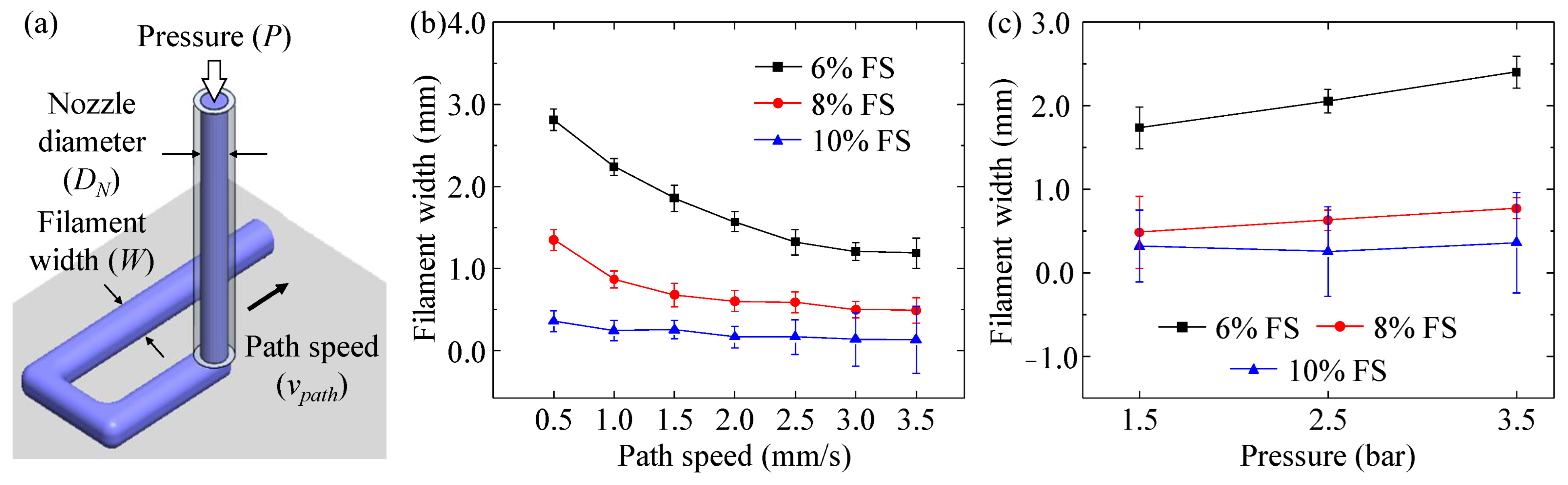
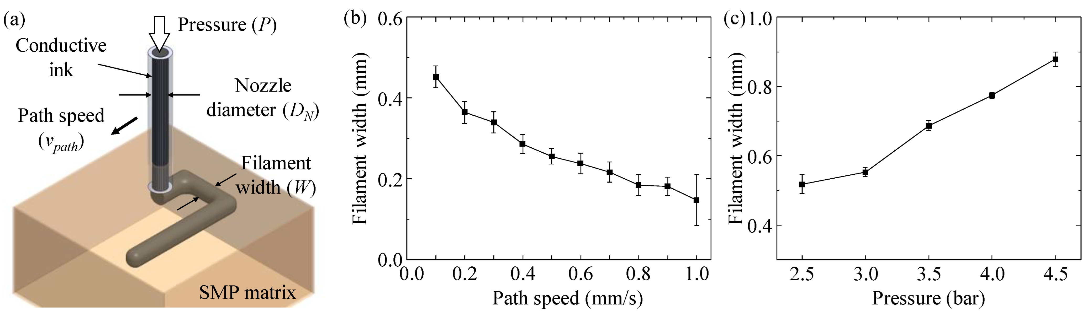
3.3. Filament Printing in DIW and E-3DP

In material extrusion 3D printing, the filament is the basic unit used to create a 3D structure, so it is important to accurately control the geometry of a filament. Herein, the impact of two key printing parameters, path speed (vpath) and pressure (P), on the SMP ink filament width (W) and corner distance in DIW was investigated, as shown in Figure 3 and Figure 4. The effects of these parameters on the conductive ink filament width in e-3DP are shown in Figure 5. As the path speed increased from 0.5 to 3.5 mm/s, the filament width decreased. The filament width of the SMP ink is influenced by the volume flow rate (Q), which remains constant at a specific dispensing pressure and nozzle diameter (DN). The volume rate is governed by this model [49]:
Q = 1 4 π D e 2 v p a t h
where Q is the volume flow rate, De is the filament diameter equivalent to filament width, and vpath is the path speed. Based on this equation, the increase in path speed results in a decrease in filament width. In addition, as presented in Figure 3b, the increase of FS led to a decrease in filament width. As shown in Figure 2a, the higher FS concentration indicated the higher viscosity of the SMP ink. When a constant dispensing pressure was applied, less ink material can be extruded in higher viscosity inks, causing the extrusion of smaller filaments. The effects of dispensing pressure on the filament width are illustrated in Figure 3c. As the pressure increased from 1.5 to 3.5 bar, the filament width increased. In addition, the SMP ink with the lowest FS concentration of 6% was most sensitive to the changing pressure. It had a lower viscosity, as depicted in Figure 2a, which resulted in larger filament widths. The dispensing pressure directly determined the volume of ink material being extruded out of the nozzle. In particular, it is given by [49]:
v o u t = P 8 η 0 L R N 2
where vout is the ink velocity at the nozzle’s exit, P is the dispensing pressure, η0 is the zero-shear-rate viscosity, L is the nozzle length, and RN is the radius of the dispensing nozzle similar to the nozzle diameter. From Equation (3), either a higher dispensing pressure or a lower viscosity of SMP ink will lead to the formation of filament with larger filament width.
The corner distance, measured as the deviation between the designed path (marked by a dashed line) and the printed filament (marked by a center, dash-dot, line), is illustrated in Figure 4a. When the path speed increased from 1.5 to 4.5 mm/s, the corner distance presented a positive parabolic trend, as shown in Figure 4b. This was due to the filament being over-deposited at a low path speed and being stretched at a high path speed. With the pressure remaining constant, a low path speed created an excessive buildup of the filament, causing an unstable pattern. The relationship described by Equation (2) implies that an increase in path speed leads to the filament stretching, resulting in a reduced filament width and a deviation from the designed path. For the SMP ink with 10% FS, a filament could not be formed at a path speed of 4.5 mm/s nor pressure of 1.5 bar due to the high viscosity. The effects of dispensing pressure on the corner distance are illustrated in Figure 4c. When the pressure increased from 1.5 to 3.5 bar, the corner distance increased. In addition, as the FS concentration increased, the corner distance decreased. This was attributed to a lower FS concentration, resulting in a lower viscosity SMP ink and greatly affecting the filament geometry upon extrusion (Equation (3)).
In e-3DP, the filament width of the conductive ink decreased when the path speed increased. On the other hand, filament width increased when the pressure increased. These trends are similar to the results in DIW, as illustrated in Figure 3. The final path speed and pressure chosen for the conductive ink were 0.3 mm/s and 3.5 bar, respectively.

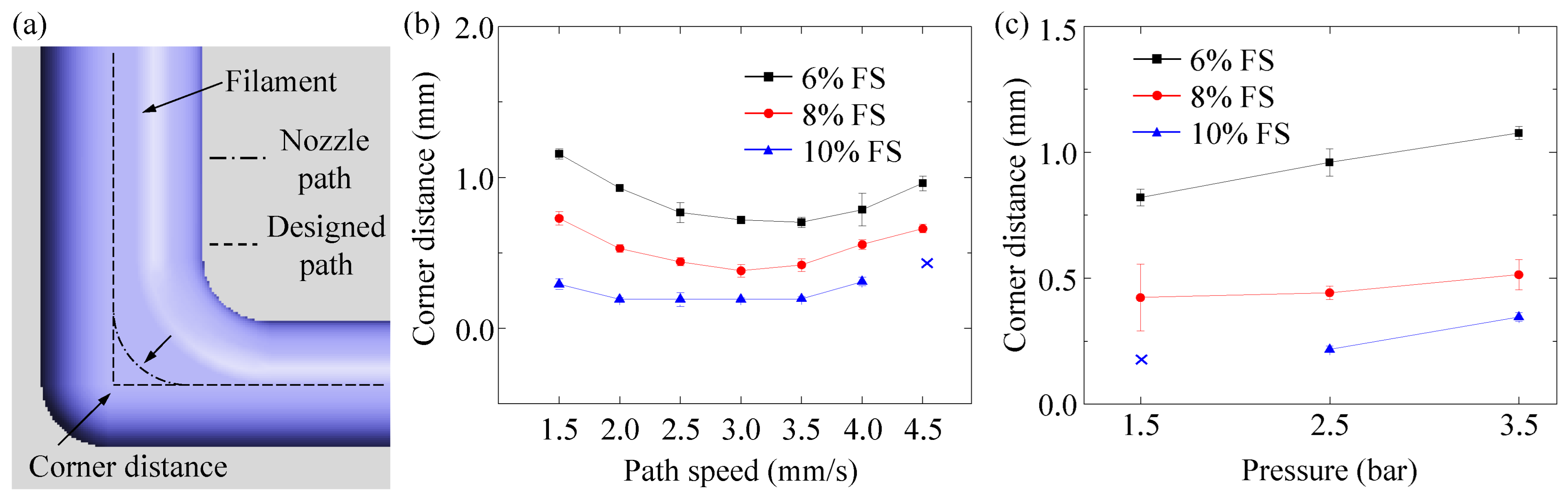
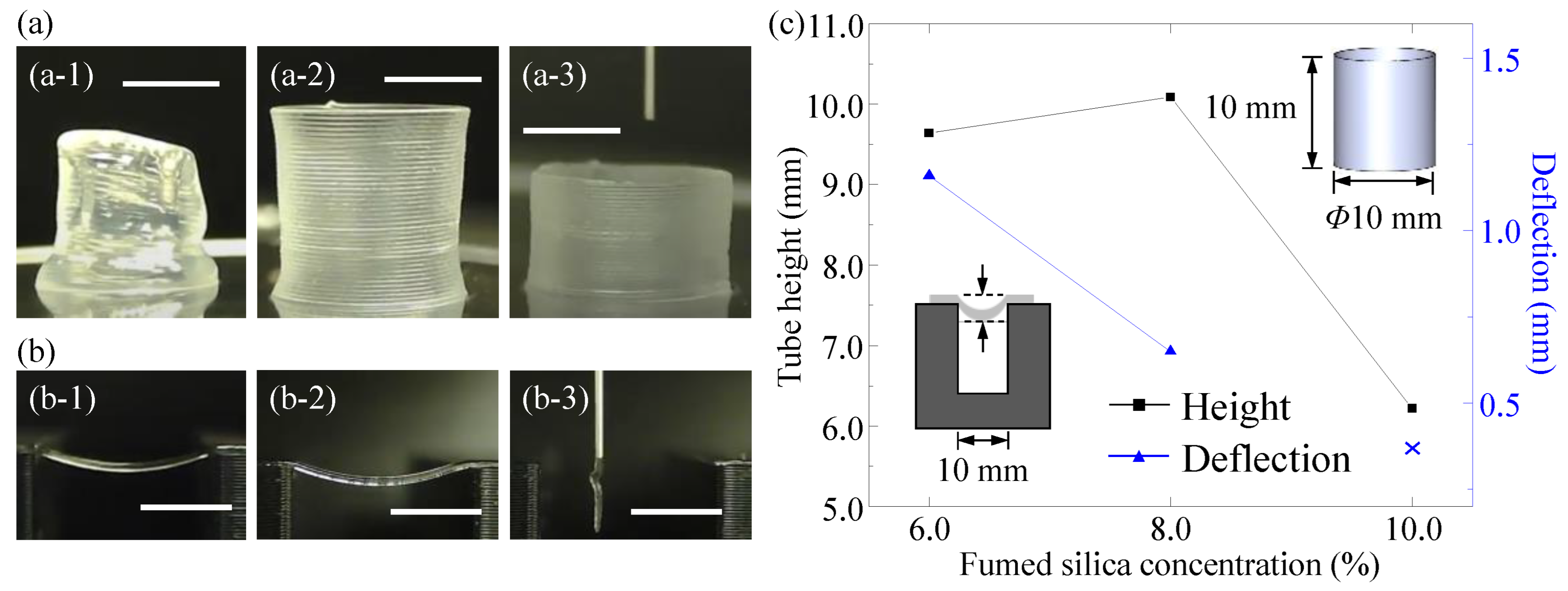
3.4. Characterization of Self-Supporting Capability

Two structures were printed to quantify the self-supporting capability. In particular, the structures were a vertical tube, depicted in Figure 6a, and a simply supported filament beam, as shown in Figure 6b. It is found that the tube from the SMP ink with the FS concentration of 8% had the most accurate height and diameter when compared to the designed tube. The schematic of the vertical tube is illustrated in Figure 6c.
When the same printing parameters were selected to print the tubes from the SMP inks with different FS concentrations, the filament with 10% FS had the smallest diameter (400 μm) because of its highest viscosity (160 Pa, as shown in Figure 2a). Consequently, when stacking these filaments into the tube, the overall height was lower than the designed value. In addition, it was noted that the filament height was smaller than the step distance along the vertical direction (400 μm). As a result, during printing, the gap was generated, which resulted in the under-deposition phenomenon, making the actual tube diameter smaller than the designed diameter. For the tube with 6% FS, the filament diameter was around 500 μm, which was expected to form the tube with the designed dimensions. However, due to the low yield stress (86 Pa, as shown in Figure 2a), the printed tube collapsed when the self-gravity-induced compression stress at the bottom layer exceeded the yield stress of the ink material [50], leading to the smaller tube height.
The filament beams made of SMP inks with different FS concentrations and their deflections over a spanning distance of 10 mm are shown in Figure 6b. The schematic of the filament beam is shown in Figure 6c. For the filament beam with the 8% FS, the maximum deflection at the spacing of 10 mm was 0.65 mm, smaller than the deflection of the 6% FS filament beam which was 1.16 mm. The 10% FS beam could not form due to the constant path speed of 2.5 mm/s, causing stretching of the ink and preventing the creation of an overhanging filament over a 10 mm spanning distance.
By comprehensively evaluating the rheological properties, dry-out process, printed filament geometries, and self-supporting capability, the SMP ink with the 8% FS was selected to print the hinge structure via the proposed 3D printing method using a path speed and pressure chosen of 1.5 mm/s and 2.5 bar, respectively.

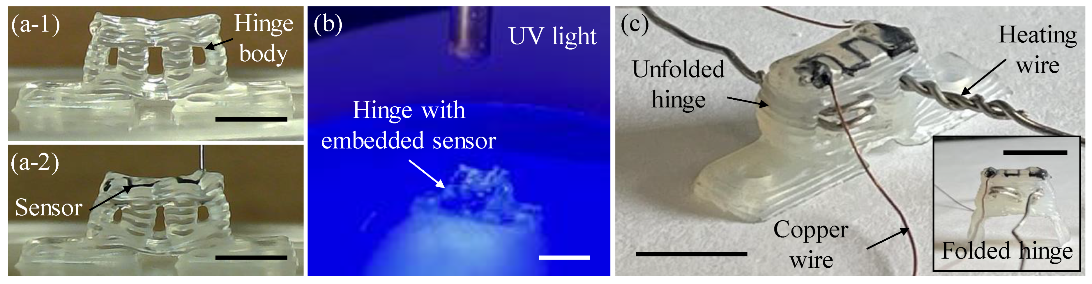
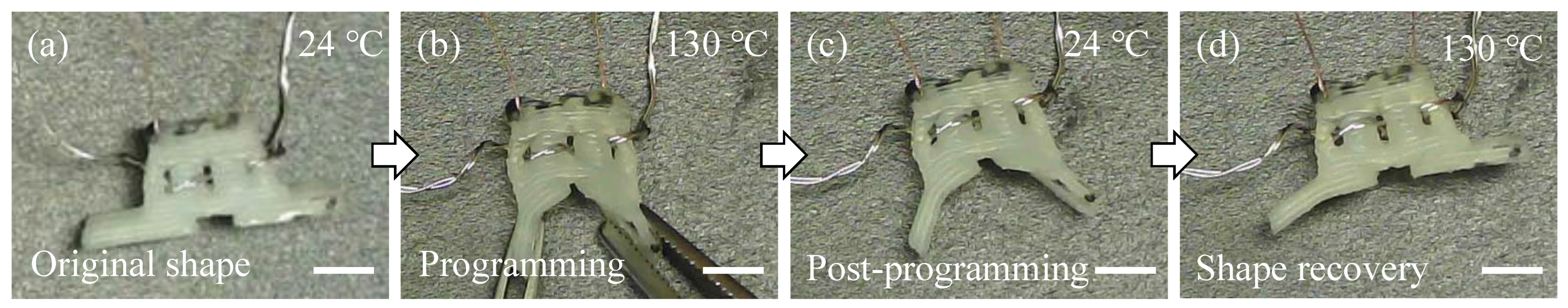
3.5. Smart Hinge Printing and Performance Testing

Based on the dry-out characterization results (Figure 2c), the maximum height of a printable structure, and acceptable deflection of a spanning feature, the hinge structure was designed with an overall length of 20.0 mm, width of 6.0 mm, height of 9.0 mm, and maximum spanning distance of 4.0 mm that was selected due to the greater influence of the weight of subsequent layers on the deflection compared to the single filament beam testing. The hinge and embedded sensor were printed as shown in Figure 7(a-1,a-2), respectively. The printing process is shown in Supplementary Materials Video S1. The SMP ink with a FS concentration of 8% was printed in air via DIW to create the hinge body at a path speed of 1.5 mm/s and a pressure of 2.5 bar (Figure 7(a-1)). The DIW process was completed in 19 min. Due to the good self-supporting capability, the hinge maintained a distinct shape in a liquid state for the e-3DP of the conductive ink.
The second dispensing nozzle was moved to the corresponding location to deposit the conductive ink into a square-wave pattern within the liquid hinge via e-3DP to create an embedded sensor using a path speed of 0.3 mm/s and a pressure of 3.5 bar (Figure 7(a-2)). The e-3DP process was completed under 1 min, resulting in a total print time of about 20 min for both the DIW and e-3DP steps. Copper wires were then inserted into the ends of the sensor and the hinge was exposed to UV radiation (Figure 7b) to cause chemical crosslinking. UV light triggered the activation of the photoinitiator, TPO, leading to the production of free radicals. These free radicals then spread throughout various polymer molecules, such as tBA, AUD, and IBOA, causing the creation of covalent bonds between tBA molecular chains through the involvement of both AUD and IBOA [12]. After crosslinking, the hinge (Figure 7c) had a heating wire woven through the slots. The hinge, after it had been programmed to stay in a folded shape, is shown in the inset of Figure 7c.
The SMP performance of the hinge was characterized after the fabrication process was completed. The hinge was heated via Joule heating using the heating wire that was inserted through the rectangular holes in the hinge (Figure 7c). The wire was heated to a temperature of 130 °C to heat the entire hinge body past its glass transition temperature (Tg) which was approximately 60 °C [51]. Assuming FS had negligible effects on Tg, the programming temperature was set to 130 °C to induce a rapid temperature change. At this temperature, the hinge was manually folded as shown in Figure 8b. Due to the excellent stretchability of the SMP resin [12], the hinge maintained the bent shape without any damage (Figure 8b). The hinge remained folded once the external temperature was removed and its temperature decreased back to 24 °C (Figure 8c). To trigger shape recovery, the hinge was heated via Joule heating again at 130 °C. It was observed that the hinge quickly switched to an unfolded configuration, as illustrated in Figure 8d in about 10 s. This behavior demonstrated the shape memory property of the SMP hinge. The programming and shape recovery can be seen in Supplementary Materials Video S2.

3.6. Smart Hinge Application Testing

As the primary objective of this study was to validate the feasibility of the proposed hybrid DIW/e-3DP method, particular attention was given to evaluating the performance of the embedded sensor. To accomplish this, the resistance of the embedded sensor was measured using a voltage divider while the mock solar panels were deployed from the mock space shuttle. The application testing setup is shown in Figure 9a, and the schematic of the voltage divider circuit is illustrated in the inset of Figure 9a. The deployment process can be seen in Supplementary Materials Video S3.
The output voltage (Vout) was recorded from the voltage divider as the smart hinges returned to their original shape. The conversion of the output voltage to the resistance of the sensor (Rs) was conducted through [52]:
R s = V i n V o u t V o u t R f
where Vin is the input voltage, which was set at 5 V, and Rf is the constant reference resistance, which was set at 540 kΩ. This varying Rs is shown in Figure 9b, and two insets show the temperature distribution of one smart hinge at the beginning and end of deployment. The initial resistance of the smart hinge was measured as 3.2 MΩ, as indicated in Figure 9b. With the increase of the temperature to 130 °C, the programmed smart hinge recovered to its original shape with the sensor resistance increasing from 3.2 to 6.8 MΩ. This resistance variation can be used to track the deformation and working status of the smart hinge upon temperature change. Since the main focuses of this study were to validate the feasibility of the proposed hybrid DIW/e-3DP method and test the capability of the sensor, the repeatability of the embedded sensor was not specifically tested. In the future, the smart hinge will be repeated until the hinge fails, while measuring the resistance. The resistance before failure will determine the life span of the smart hinge. Further, as shown in Video S3, the solar panels did not unfold to 180° as the clips that were used for Joule heating restricted the unfolding process. The hinges did exhibit the shape memory characteristic and could monitor the varying resistance. Future work will include adjusting the setup so the hinges can fully deploy the solar panels. Additionally, both geometry and topology [25,53] can be adjusted to optimize the smart hinge performance.

4. Conclusions and Future Work

This study successfully applied a hybrid DIW/e-3DP method to fabricate smart hinges with complex geometries with embedded strain sensors that monitored its deformation during shape recovery. The chosen material for the ink was a photocurable resin, tBA/AUD, in which FS particles were added to create a self-supporting SMP ink. A comprehensive characterization of key DIW/e-3DP properties, such as rheological testing and dry-out characterization of the SMP inks with different FS concentrations, the effect of path speed and pressure on filament geometry, and self-supporting printing tests, were investigated to ascertain their impact on the printability of the smart hinges. The optimal parameters obtained from these characterizations enabled the printing of liquid-state smart hinges using DIW and facilitated the utilization of e-3DP for depositing conductive ink to create strain sensors. Some of the main conclusions are listed:
  • The concentration of FS was found to have a significant impact on the properties of the SMP ink. Specifically, a lower FS concentration resulted in lower yield stress, shorter thixotropic response time, and lower mass loss over time.
  • An 8% FS concentration was chosen as the ideal concentration to achieve better control over filament geometries and exhibited the best self-supporting capability.
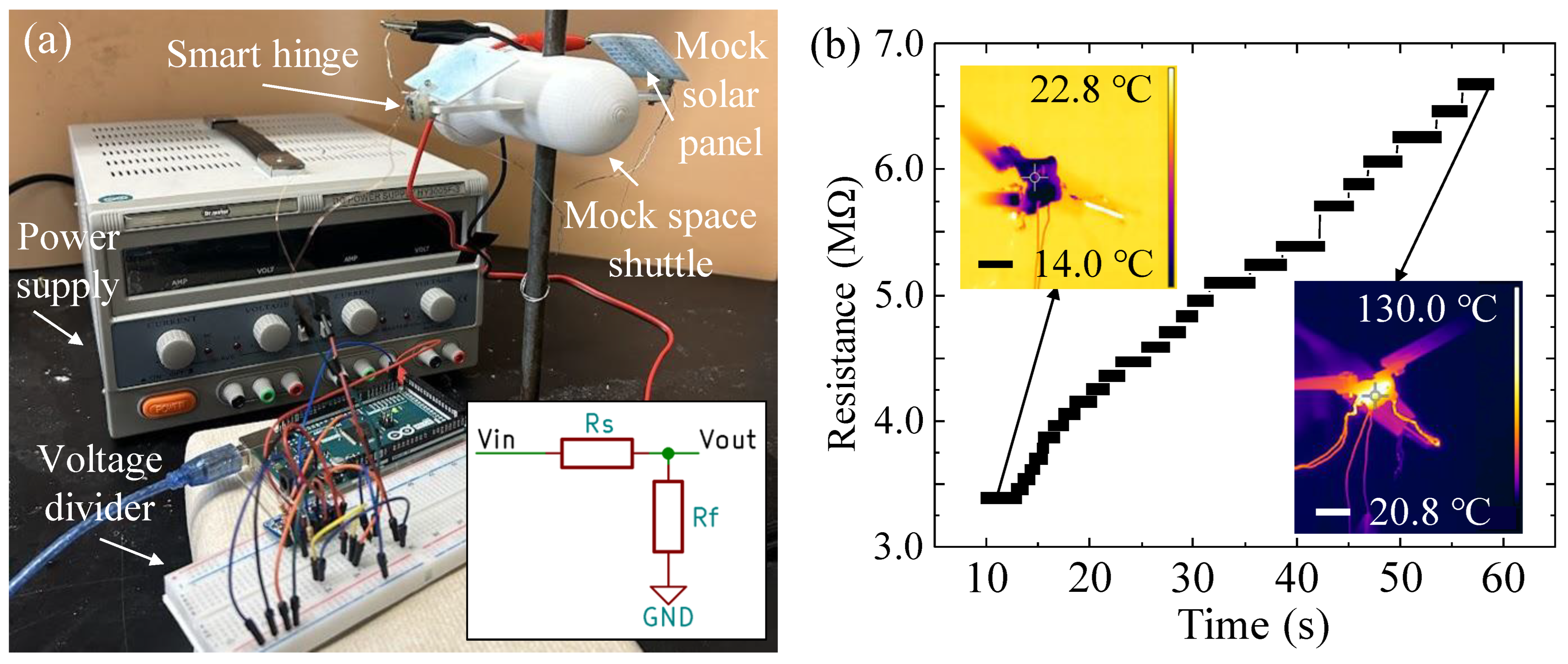
  • The resistance of the hinge was measured using the e-3DP strain sensor and voltage divider, and the smart hinges were able to deploy mock solar panels on a mock space shuttle.
  • This method holds great promise for manufacturing diverse functional devices with embedded sensors in the future.
Future work may focus on comprehensively evaluating the repeatability of hinge deployment, assessing its fatigue resistance, and adjusting the application testing setup. It is noted that both penetration depth of a photocurable resin and maximum height of a printable part from self-supporting ink may constrain the proposed approach to construct scale-up structures. In this case, a localized hybrid 3D printing strategy will be utilized, in which the DIW/e-3DP approach is only applied to the given section of a 3D part that needs any embedded features. The rest of the part can be printed via traditional DIW, where a crosslinking mechanism will be performed during printing to cause the rapid solidification of the printed section. Additionally, further theoretical exploration is needed to uncover the underlying principles behind designing yield–stress fluids that can serve as both self-supporting inks for DIW and matrix baths for e-3DP, categorizing their rheological properties and material behavior to optimize ink formulations. Finite element method-based simulations will also be performed to predict the hinge deformation. These advancements will contribute to the progress of additive manufacturing techniques and broaden the scope of functional devices with embedded sensors that can be manufactured.

Supplementary Materials

The following supporting information can be downloaded at: https://www.mdpi.com/article/10.3390/machines11070686/s1, Video S1: Hybrid DIW/e-3DP of smart hinge; Video S2: Shape memory performance testing; Video S3: Application testing: deploying mock solar panels from a mock space shuttle.

Author Contributions

Conceptualization, L.R., E.B. and Y.J.; methodology, L.R., E.B., W.H., K.M., T.T. and K.L.; software, L.R., E.B. and T.T.; validation, L.R., E.B. and T.T.; formal analysis, L.R., E.B., W.H., K.M. and T.T.; investigation, L.R., E.B., W.H., T.T. and K.L.; resources, J.Z. and Y.J.; data curation, L.R., E.B. and T.T.; writing—original draft preparation, L.R., E.B. and Y.J.; writing—review and editing, L.R., E.B., T.T., J.Z. and Y.J.; supervision, J.Z. and Y.J.; project administration, Y.J. All authors have read and agreed to the published version of the manuscript.

Funding

Lily Raymond would like to acknowledge the support from the Nevada NASA Space Grant Consortium through the Graduate Research Opportunity Fellowship (Grant number: 80NSSC20M00043) as well as the support from the National Science Foundation Graduate Research Fellowship Program through NSHE sub-award number: AWD0002282-1937966. Any opinions, findings, conclusions, or recommendations expressed in this material are those of the authors and do not necessarily reflect the views of the National Science Foundation.

Data Availability Statement

The data that support the findings of this study are available from the corresponding author (yifeij@unr.edu) upon reasonable request.

Conflicts of Interest

The authors declare no conflict of interest.

References

  1. Asar, A.; Irfan, M.S.; Khan, K.A.; Zaki, W.; Umer, R. Self-sensing shape memory polymer composites reinforced with functional textiles. Compos. Sci. Technol. 2022, 221, 109219. [Google Scholar] [CrossRef]
  2. Booth, R.E.; Khanna, C.; Schrickx, H.M.; Siddika, S.; Al Shafe, A.; O’Connor, B.T. Electrothermally actuated semitransparent shape memory polymer composite with application as a wearable touch sensor. ACS Appl. Mater. Interfaces 2022, 14, 53129–53138. [Google Scholar] [CrossRef] [PubMed]
  3. Lantada, A.D.; De Blas Romero, A.; Tanarro, E.C. Micro-vascular shape-memory polymer actuators with complex geometries obtained by laser stereolithography. Smart Mater. Struct. 2016, 25, 065018. [Google Scholar] [CrossRef] [Green Version]
  4. Huang, X.; Panahi-Sarmad, M.; Dong, K.; Li, R.; Chen, T.; Xiao, X. Tracing evolutions in electro-activated shape memory polymer composites with 4D printing strategies: A systematic review. Compos. Part Appl. Sci. Manuf. 2021, 147, 106444. [Google Scholar] [CrossRef]
  5. Leng, J.; Lan, X.; Liu, Y.; Du, S. Shape-memory polymers and their composites: Stimulus methods and applications. Prog. Mater. Sci. 2011, 56, 1077–1135. [Google Scholar] [CrossRef]
  6. Raasch, J.; Ivey, M.; Aldrich, D.; Nobes, D.S.; Ayranci, C. Characterization of polyurethane shape memory polymer processed by material extrusion additive manufacturing. Addit. Manuf. 2015, 8, 132–141. [Google Scholar] [CrossRef]
  7. Herath, M.; Emmanuel, C.; Jeewantha, J.; Epaarachchi, J. In-Situ Performance Evaluation of Large Shape Memory Polymer Components via Distributed Optical Fibre Sensors. In Proceedings of the 2021 10th International Conference on Information and Automation for Sustainability (ICIAfS), Negambo, Sri Lanka, 11–13 August 2021. [Google Scholar]
  8. Ke, D.; Chen, Z.; Momo, Z.Y.; Jiani, W.; Xuan, C.; Xiaojie, Y.; Xueliang, X. Recent advances of two-way shape memory polymers and four-dimensional printing under stress-free conditions. Smart Mater. Struct. 2020, 29, 023001. [Google Scholar] [CrossRef]
  9. Liu, Y.; Lv, H.; Lan, X.; Leng, J.; Du, S. Review of electro-active shape-memory polymer composite. Compos. Sci. Technol. 2009, 69, 2064–2068. [Google Scholar] [CrossRef]
  10. Mu, T.; Liu, L.; Lan, X.; Liu, Y.; Leng, J. Shape memory polymers for composites. Compos. Sci. Technol. 2018, 160, 169–198. [Google Scholar] [CrossRef]
  11. Xia, Y.; He, Y.; Zhang, F.; Liu, Y.; Leng, J. A review of shape memory polymers and composites: Mechanisms, materials, and applications. Adv. Mater. 2021, 33, 2000713. [Google Scholar] [CrossRef]
  12. Zhang, B.; Li, H.; Cheng, J.; Ye, H.; Sakhaei, A.H.; Yuan, C.; Rao, P.; Zhang, Y.; Chen, Z.; Wang, R.; et al. Mechanically robust and UV-curable shape-memory polymers for digital light processing based 4D printing. Adv. Mater. 2021, 33, 2101298. [Google Scholar] [CrossRef]
  13. Lan, X.; Liu, L.; Pan, C.; Li, F.; Liu, Z.; Hou, G.; Sun, J.; Dai, W.; Wang, L.; Yue, H.; et al. Smart solar array consisting of shape-memory releasing mechanisms and deployable hinges. AIAA J. 2021, 59, 2200–2213. [Google Scholar] [CrossRef]
  14. Bartlett, N.W.; Tolley, M.T.; Overvelde, J.T.B.; Weaver, J.C.; Mosadegh, B.; Bertoldi, K.; Whitesides, G.M.; Wood, R.J. 3D-printed, functionally graded soft robot powered by combustion. Science 2015, 349, 161–165. [Google Scholar] [CrossRef] [PubMed] [Green Version]
  15. Akbari, S.; Sakhaei, A.H.; Kowsari, K.; Yang, B.; Serjouei, A.; Yuanfang, Z.; Ge, Q. Enhanced multimaterial 4D printing with active hinges. Smart Mater. Struct. 2018, 27, 065027. [Google Scholar] [CrossRef]
  16. Sokolowski, W.; Metcalfe, A.; Hayashi, S.; Yahia, L.; Raymond, J. Medical applications of shape memory polymers. Biomed. Mater. Bristol Engl. 2007, 2, S23–S27. [Google Scholar] [CrossRef]
  17. Lendlein, A.; Langer, R. Biodegradable, elastic shape-memory polymers for potential biomedical applications. Science 2002, 296, 1673–1676. [Google Scholar] [CrossRef]
  18. Nohut, S.; Schwentenwein, M. Vat photopolymerization additive manufacturing of functionally graded materials: A review. J. Manuf. Mater. Process 2022, 6, 17. [Google Scholar] [CrossRef]
  19. Zhao, W.; Wang, Z.; Zhang, J.; Wang, X.; Xu, Y.; Ding, N.; Peng, Z. Vat photopolymerization 3D printing of advanced soft sensors and actuators: From architecture to function. Adv. Mater. Technol. 2021, 6, 2001218. [Google Scholar] [CrossRef]
  20. Pagac, M.; Hajnys, J.; Ma, Q.-P.; Jancar, L.; Jansa, J.; Stefek, P.; Mesicek, J. A review of vat photopolymerization technology: Materials, applications, challenges, and future trends of 3D printing. Polymers 2021, 13, 598. [Google Scholar] [CrossRef] [PubMed]
  21. Petousis, M.; Vidakis, N.; Mountakis, N.; Karapidakis, E.; Moutsopoulou, A. Functionality versus sustainability for PLA in MEX 3D printing: The impact of generic process control factors on flexural response and energy efficiency. Polymers 2023, 15, 1232. [Google Scholar] [CrossRef]
  22. Kumaresan, R.; Samykano, M.; Kadirgama, K.; Ramasamy, D.; Keng, N.W.; Pandey, A.K. 3D printing technology for thermal application: A brief review. J. Adv. Res. Fluid Mech. Therm. Sci. 2021, 83, 84–97. [Google Scholar] [CrossRef]
  23. Nam, S.; Pei, E. The influence of shape changing behaviors from 4D printing through material extrusion print patterns and infill densities. Materials 2020, 13, 3754. [Google Scholar] [CrossRef]
  24. Garcia, R.C.A.; Kim, H.; Garcia, D.M.F.; Chavez, L.; Castañeda, M.; Tseng, T.-L.B.; Lin, Y. Characterization of shape memory polymer parts fabricated using material extrusion 3D printing technique. Rapid Prototyp. J. 2018, 25, 322–331. [Google Scholar] [CrossRef]
  25. Sun, Y.; Lueth, T.C. Enhancing torsional stiffness of continuum robots using 3-D topology optimized flexure joints. In IEEE/ASME Transactions on Mechatronics; IEEE: Piscataway, NJ, USA, 2023; pp. 1–9. [Google Scholar] [CrossRef]
  26. Sam-Daliri, O.; Ghabezi, P.; Flanagan, T.; Finnegan, W.; Mitchell, S.; Harrison, N. Recovery of Particle Reinforced Composite 3D Printing Filament from Recycled Industrial Polypropylene and Glass Fibre Waste. In Proceedings of the 8th World Congress on Mechanical, Chemical, and Material Engineering (MCM’22), Prague, Czech Republic, 31 July–2 August 2022. [Google Scholar] [CrossRef]
  27. Wan, X.; Luo, L.; Liu, Y.; Leng, J. Direct ink writing based 4D printing of materials and their applications. Adv. Sci. 2020, 7, 2001000. [Google Scholar] [CrossRef]
  28. Valentin, N.; Hua, W.; Kasar, A.K.; Raymond, L.; Menezes, P.L.; Jin, Y. Direct ink writing to fabricate porous acetabular cups from titanium alloy. Bio-Des. Manuf. 2023, 6, 121–135. [Google Scholar] [CrossRef]
  29. Baniasadi, H.; Ajdary, R.; Trifol, J.; Rojas, O.J.; Seppälä, J. Direct ink writing of aloe vera/cellulose nanofibrils bio-hydrogels. Carbohydr. Polym. 2021, 266, 118114. [Google Scholar] [CrossRef]
  30. Shiwarski, D.J.; Hudson, A.R.; Tashman, J.W.; Feinberg, A.W. Emergence of FRESH 3D printing as a platform for advanced tissue biofabrication. APL Bioeng. 2021, 5, 010904. [Google Scholar] [CrossRef] [PubMed]
  31. Zhao, J.; He, N. A mini-review of embedded 3D printing: Supporting media and strategies. J. Mater. Chem. B 2020, 8, 10474–10486. [Google Scholar] [CrossRef]
  32. Hua, W.; Mitchell, K.; Kariyawasam, L.S.; Do, C.; Chen, J.; Raymond, L.; Valentin, N.; Coulter, R.; Yang, Y.; Jin, Y. Three-dimensional printing in stimuli-responsive yield-stress fluid with an interactive dual microstructure. ACS Appl. Mater. Interfaces 2022, 14, 39420–39431. [Google Scholar] [CrossRef]
  33. Kuang, X.; Chen, K.; Dunn, C.K.; Wu, J.; Li, V.C.F.; Qi, H.J. 3D printing of highly stretchable, shape-memory, and self-healing elastomer toward novel 4D printing. ACS Appl. Mater. Interfaces 2018, 10, 7381–7388. [Google Scholar] [CrossRef]
  34. Chen, Q.; Sukmanee, T.; Rong, L.; Yang, M.; Ren, J.; Ekgasit, S.; Advincula, R. A dual approach in direct ink writing of thermally cured shape memory rubber toughened epoxy. ACS Appl. Polym. Mater. 2020, 2, 5492–5500. [Google Scholar] [CrossRef]
  35. Muth, J.T.; Vogt, D.M.; Truby, R.L.; Mengüç, Y.; Kolesky, D.B.; Wood, R.J.; Lewis, J.A. Embedded 3D printing of strain sensors within highly stretchable elastomers. Adv. Mater. 2014, 26, 6307–6312. [Google Scholar] [CrossRef]
  36. Zhang, C.; Qu, M.; Fu, X.; Lin, J. Review on microscale sensors with 3D engineered structures: Fabrication and applications. Small Methods 2022, 6, 2101384. [Google Scholar] [CrossRef] [PubMed]
  37. Hua, W.; Mitchell, K.; Raymond, L.; Valentin, N.; Coulter, R.; Jin, Y. Embedded 3D printing of PDMS-based microfluidic chips for biomedical applications. J. Manuf. Sci. Eng. 2022, 145, 011002. [Google Scholar] [CrossRef]
  38. Jin, Y.; Song, K.; Gellermann, N.; Huang, Y. Printing of hydrophobic materials in fumed silica nanoparticle suspension. ACS Appl. Mater. Interfaces 2019, 11, 29207–29217. [Google Scholar] [CrossRef]
  39. Jiang, F.; Zhou, M.; Drummer, D. Effects of fumed silica on thixotropic behavior and processing window by UV-assisted direct ink writing. Polymers 2022, 14, 3107. [Google Scholar] [CrossRef]
  40. Chung, S.-C.; Hahm, W.-G.; Im, S.-S. Poly(ethylene terephthalate)(PET) nanocomposites filled with fumed silicas by melt compounding. Macromol. Res. 2002, 10, 221–229. [Google Scholar] [CrossRef]
  41. Jin, Y.; Liu, C.; Chai, W.; Compaan, A.; Huang, Y. Self-supporting nanoclay as internal scaffold material for direct printing of soft hydrogel composite structures in air. ACS Appl. Mater. Interfaces 2017, 9, 17456–17465. [Google Scholar] [CrossRef]
  42. Sakhakarmy, M.; Tian, S.; Raymond, L.; Xiong, G.; Chen, J.; Jin, Y. Printability study of self-supporting graphene oxide-laponite nanocomposites for 3D printing applications. Int. J. Adv. Manuf. Technol. 2021, 114, 343–355. [Google Scholar] [CrossRef]
  43. Xie, H.; Yang, K.-K.; Wang, Y.-Z. Photo-cross-linking: A powerful and versatile strategy to develop shape-memory polymers. Prog. Polym. Sci. 2019, 95, 32–64. [Google Scholar] [CrossRef]
  44. Truby, R.L.; Wehner, M.; Grosskopf, A.K.; Vogt, D.M.; Uzel, S.G.M.; Wood, R.J.; Lewis, J.A. Soft somatosensitive actuators via embedded 3D printing. Adv. Mater. 2018, 30, 1706383. [Google Scholar] [CrossRef] [PubMed] [Green Version]
  45. Saramito, P. A new elastoviscoplastic model based on the Herschel–bulkley viscoplastic model. J. Non-Newton. Fluid Mech. 2009, 158, 154–161. [Google Scholar] [CrossRef] [Green Version]
  46. Jamorin International. Available online: https://jamorin.com/products/tert-butyl-acrylate-tba/#:~:text=tert%2DButyl%20Acrylate%20(TBA)%20is%20an%20ester%20of%20acrylic,and%20a%20long%20hydrophobic%20group (accessed on 10 June 2023).
  47. Australian Government Department of Climate Change, Energy, the Environment and Water. Available online: https://www.dcceew.gov.au/environment/protection/npi/substances/fact-sheets/acrylic-acid#:~:text=As%20a%20volatile%20organic%20compound,low%20growth%20rate%20in%20plants (accessed on 10 June 2023).
  48. U.S. Environmental Protection Agency. Available online: https://www.epa.gov/indoor-air-quality-iaq/technical-overview-volatile-organic-compounds#:~:text=Volatile%20organic%20compounds%2C%20or%20VOCs,of%20temperature%20and%20pressure3 (accessed on 10 June 2023).
  49. Jin, Y.; Chai, W.; Huang, Y. Printability study of hydrogel solution extrusion in nanoclay yield-stress bath during printing-then-gelation biofabrication. Mater. Sci. Eng. C 2017, 80, 313–325. [Google Scholar] [CrossRef] [PubMed]
  50. Jin, Y.; Xiong, R.; Antonelli, P.J.; Long, C.J.; McAleer, C.W.; Hickman, J.J.; Huang, Y. Nanoclay suspension-enabled extrusion bioprinting of three-dimensional soft structures. J. Manuf. Sci. Eng. 2021, 143, 313–325. [Google Scholar] [CrossRef]
  51. Wei, X.; Li, H.; He, X.; Li, Z.; Ye, H.; Xue, W.; Ge, Q. Shape Memory Polymer-Based Stiffness Variable Soft Actuator Via Digital Light Processing-Based 3D Printing. In Proceedings of the 2021 27th International Conference on Mechatronics and Machine Vision in Practice (M2VIP), Shanghai, China, 26–28 November 2021. [Google Scholar]
  52. All About Circuits. Available online: https://www.allaboutcircuits.com/tools/voltage-divider-calculator/ (accessed on 29 March 2023).
  53. Qiu, L.; Yue, X.; Xie, Z. Design and analysis of multicavity flexure hinge (MCFH) based on three-dimensional continuum topology optimization. Mech. Mach. Theory 2019, 139, 21–33. [Google Scholar] [CrossRef]
Figure 1. Schematic of the hybrid DIW/e-3DP printing method and application of the smart hinge. (a) DIW of the hinge from the self-supporting SMP ink; (b) E-3DP of the conductive grease to act as the strain sensor within the liquid hinge structure; (c) UV crosslinking of the hinge with the embedded sensor; (d) Addition of a heating wire to the crosslinked hinge to induce an external stimulus; Smart hinge deploying mock solar panels from a mock space shuttle, transitioning from its (e-1) folded to (e-2) unfolded shape in response to an external stimulus.
Machines 11 00686 g001
Figure 2. The (a) yield stress, (b) thixotropic response time, and (c) dry-out properties of SMP inks with different FS concentrations.
Machines 11 00686 g002
Figure 3. (a) Schematic of the printing parameters in DIW. Filament width as a function of (b) path speed and (c) pressure.
Machines 11 00686 g003
Figure 4. (a) Schematic of the corner distance in DIW. Corner distance as a function of (b) path speed and (c) pressure.
Machines 11 00686 g004
Figure 5. (a) Schematic of the printing parameters in e-3DP. Filament width as a function of (b) path speed and (c) pressure.
Machines 11 00686 g005
Figure 6. (a) Tube printing for: (a-1) 6% FS, (a-2) 8% FS, and (a-3) 10% FS; (b) Filament beam printing for: (b-1) 6% FS, (b-2) 8% FS, and (b-3) 10% FS; (c) Tube height and deflection of filament beam as a function of FS concentration. All scale bars: 5.00 mm.
Machines 11 00686 g006
Figure 7. (a-1) DIW of the hinge body and (a-2) e-3DP of the sensor. Scale bars: 5.00 mm; (b) Hinge with the embedded sensor during the UV crosslinking step. Scale bar: 10.00 mm; (c) Hinge structure after crosslinking (inset: programmed, folded hinge). Scale bars: 10.00 mm.
Machines 11 00686 g007
Figure 8. (a) Smart hinge in its original shape at 24 °C; (b) Programming at 130 °C; (c) Folded hinge after post-programming at 24 °C; (d) Shape recovery of the smart hinge at 130 °C. All scale bars: 5.00 mm.
Machines 11 00686 g008
Figure 9. (a) Application testing setup (inset: schematic of the voltage divider circuit); (b) Variable resistance as a function of time during the deployment of mock solar panels from the mock space shuttle (insets: temperature distribution of one of the smart hinges during deployment. Scale bars: 10.00 mm).
Machines 11 00686 g009
Disclaimer/Publisher’s Note: The statements, opinions and data contained in all publications are solely those of the individual author(s) and contributor(s) and not of MDPI and/or the editor(s). MDPI and/or the editor(s) disclaim responsibility for any injury to people or property resulting from any ideas, methods, instructions or products referred to in the content.

