Article

Characterization of Dimensional Variations in Turning Process for Multistep Rotary Shaft of High-Speed Motorized Spindle

State Key Laboratory of Mechanical System and Vibration, School of Mechanical Engineering, Shanghai Jiao Tong University, Shanghai 200240, China
*
Author to whom correspondence should be addressed.
These authors contributed equally to this work.
Machines 2023, 11(5), 561; https://doi.org/10.3390/machines11050561
Submission received: 29 April 2023 / Revised: 12 May 2023 / Accepted: 14 May 2023 / Published: 16 May 2023
(This article belongs to the Special Issue Advanced Manufacturing and Quality Control for Engines)

Abstract

:
The surface accuracy of a multistep rotary shaft is very important in manufacturing and the assembly process of the high-speed motorized spindle of CNC machine tools, which is closely related to the machined dimensional variation induced by the turning process. This paper attempts to enhance a comprehensive understanding of the impact of different locating-error sources and machine toolpaths on the machined dimensional variation for multistep rotary parts of the high-speed motorized spindle in the turning process. A modeling method and a compensation strategy of dimensional variation are introduced in this paper and based on the relationship definition between the error sources and the machined surface using the differential motion vector and stream-of-variation methods. Validation experiments were conducted to verify the proposed model. Additionally, the relationship between locating errors and dimensional variation was investigated with varied case studies, providing a theoretical methodology for the prediction and characterization of the expected dimensional variations of the surface machined with the given conditions.

1. Introduction

The high-speed motorized spindle is new equipment that integrates a machine tool spindle and spindle motor, usually in conjunction with bearings, rotors and other mechanisms, as shown in Figure 1, which is crucial for machine tool transmission. Its manufacturing accuracy is very important, which directly impacts the service accuracy of machine tools. The dimensional variation of the machined surface should be strictly maintained with high-quality requirements in the turning process for the multistep rotary shaft of the high-speed motorized spindle. The main task is to enhance the machined surface quality based on the optimal process design and error compensation, which highly relies on effective modeling and characterization of the expected dimensional variations of the surface machined with the given conditions.

1.1. Literature Review

1.1.1. The Impact of Various Errors on Surface Quality

The effect of the various locating errors and process parameters on the dimensional errors of the machined surface has been considerably investigated in research. Generally, this research has focused on the modelling of machining errors in the machining process under different conditions. In the machining process, the cumulative transmission of various error sources, such as machine tools, cutting tools, fixtures, and workpieces, can affect the dimensional accuracy of workpieces. According to Ramesh [1], quasistatic errors (i.e., the machine toolpath errors, fixture errors, and datum errors) account for about 70% of overall machining errors. In order to reduce these machining errors, multistep compensation machining processes are usually used to remove workpiece materials to obtain higher manufacturing quality that cannot be achieved by a single process. Many researchers have established varied models for modeling machining-error sources to reduce the influence of various main error sources in processing. Cai et al. [2] presented a robust design scheme for fixtures to minimize position errors. An analysis method was proposed to describe how the localization errors impacted the datum geometric errors of the workpiece [3]. Jin et al. [4] analyzed the degree of influence of various error sources, such as tools, fixtures, and datums, on the surface quality for the plane milling process. Chen et al. [5] constructs the mapping relationship between the tolerance zones of machine tool components for the surface quality of the machined workpiece under the motion of machine tool axes. Qing et al. [6] analyzed the mapping relationship between clamping layout and machining quality for the drilling process of non-regular parts. In addition to errors in the machining system, individual technical operations and selection of process parameters can also have an impact on the quality of the machined surface. Zmarzły [7] pointed out that in the bearing machining process, forging, turning, heat treatment, and grinding contribute differently to the final bearing surface corrugation and showed that the waviness of the surface is an inheritance factor caused by individual operations of the rolling-bearing-rings manufacturing process. Zheng et al. [8] pointed out that in the machining of a paddle, different machining parameters have a large effect on surface quality parameters, such as the roughness of the paddle. The main issue of the above techniques is clarifying the complicated interactions between different errors from different stages. Generally, due to the complex geometric mechanism of the workpiece, it is difficult to shape it in one process and often requires multiple work steps, so it is necessary to establish the mapping relationship between the error of each process and the final surface quality of the product.
To describe the cumulative relationship of error transfer between multiple processes, the stream-of-variation (SoV) models for multistage machining processes (MMPs) was developed in the 1990s. Huang et al. [9] built a nonlinear variation propagation model for the multi-process error-transfer process. On this basis, Djurdjanovic et al. [10] linearized the model using the Taylor expansion and obtained a linear model. An explicit linear variation propagation model for multi-process machining and assembly processes was developed by Zhou et al. [11]. To solve general non-orthogonal fixture layouts, Loose et al. [12] built an SoV model using kinematic analysis methods.
The machining-process-induced errors are introduced into the SoV model based on differential motion vectors (DMVs) [13]. This model extends the fields of application. The SoV model based on DMVs for MMPs with fixtures that are based on locating surfaces has been proposed by Abellan-Nebot and Liu. [14]. The complicated error interaction between the current stage and other stages for cubic workpieces can be mathematically described, and the machining error for cubic workpieces can be predicted from the above works.

1.1.2. Error-Compensation Method for Workpiece Features

Error prediction is the first step to enhance the machining quality. Based on that, some error-compensation research works have been conducted. The modeling complex-network theory has been applied to construct the machining-error propagation network and obtain the key control processes for the machining quality [15].
The error-compensation methods commonly used in the machining field are divided into real-time compensation and predictive compensation. In terms of real-time compensation, Zeng et al. [16] proposed a position measurement method based on a laser displacement sensor to adjust the spindle position of the machine tool in real time to achieve online compensation of the hole-position error. Du et al. [17] proposed a comprehensive error-compensation method containing three major error sources: geometric error, thermal error, and force error. Deng et al. [18] proposed a new method of geometric-error identification using a tracking interferometer that considers the rigid-body motion constraint, which is more robust to random factors and not only improves the identification accuracy but also reduces the maximum angular-positioning error by 84% after compensation. Pan et al. [19] achieved the real-time compensation of the tool tip point position by arranging temperature sensors on the mechanical spindle and combining it with a regression model for spindle thermal-error prediction. In terms of predictive compensation, Rangappa et al. [20] constructed a coaxiality-error prediction model for high-precision rotary axis turning by the response surface method and optimized the compensation for coaxiality error by the Big Bang and Big Crunch and Rao algorithms. Zhu et al. [21] transformed the errors of fixture and datum to the error of toolpath by using the SoV model and equivalent-errors model. The accuracy and effectiveness of the proposed method were verified by a series of cutting experiments. Jin et al. [22] built a casting-molding-size prediction model by orthogonal experiments for the multi-process machining process of investment casting, based on which the error compensation control of heat treatment of investment casting was realized. Wei et al. [23] built a PCR model of spindle thermal error to improve the prediction accuracy of the thermal-error compensation model for CNC machine tools, which improved the predictive compensation accuracy by 23.4%. By using rigid-body kinematics, Okafor et al. [24] derived a machine-toolpath-error model for compensating machining errors in three-axis vertical machining centers. Applying the thermal-error-compensation system to the lathe reduced the thermal drift of the workpiece diameter from 35 μm to 6 μm [25]. In order to systematically present the relationship between the cutting-force-induced errors and the current of the spindle motor, a back-propagation neural-network algorithm was used to establish an error model caused by the cutting force. Through this model, a real-time error-compensation system was built [26].
In machining processes, there is a phenomenon known as error equivalence, where the fixture error, datum error, and toolpath error can produce the same machining error on workpiece features. [27,28]. Several authors devoted their efforts to describe the error-equivalent phenomenon and compensate for the main error sources. Wang et al. [27] developed an equivalent-fixture-error (EFE) model to convert datum and machine toolpath errors into equivalent fixture errors. Wang and Huang [28] applied the error-equivalent phenomenon to cancel out the main machining-error sources by adjusting the height of the corresponding fixture locators. Yang et al. [29] proposed a new EFE model that can concurrently transform the path error of the machine tool, the datum error, and the deformation error of the workpiece into their corresponding equivalent errors of the fixture location. This model is not restricted to the case of orthogonal 3-2-1 layouts, as it can also deal with general non-orthogonal fixture layouts. Although the above research can improve the manufacturing quality for cubic workpieces by their corresponding compensation strategies, due to the different clamping scheme for cubic workpieces, it cannot be directly applied to multistage turning processes (MTPs) for cylindrical workpieces.
In order to overcome the above-mentioned limitation and to analyze the propagation of variation for MTPs, Du et al. [30] developed a DMV-based three-dimensional variation propagation model for rotating-workpiece MTPs. To describe the relationship between the various types of errors and the variation in product characteristics, a linear model was developed. Using this model, a two-stage Bayesian method has been proposed for the estimation of the process control parameters during the start-up phase of the MTPs [31]. A Jacobian–Torsor was used to establish a new variation propagation model for general-shape workpieces in MMPs [32]. Although the above research can predict the machining errors for MTPs, it is necessary to establish a comprehensive model that can predict and compensate for the machining errors simultaneously. In addition, the error prediction model for the positioning method of the complex stepped shaft also should be considered.

1.2. Paper Research Content

This paper develops a characterization model of dimensional variations for the multistep rotary shaft based on the DMV and SoV model. Based on the proposed model, a systematic description of locating errors and the corresponding equivalent-error compensation methodology is presented for the turning process of the multistep rotary shaft with a general fixture layout. Case studies are conducted to investigate the relationship between locating errors and dimensional variation. The remaining sections are organized as follows. Section 2 introduces the representations of the mechanism of locating errors and presents the procedures of the corresponding equivalent-error compensation methodology. Section 3 presents case studies for validation of the method proposal. Finally, Section 4 is the conclusion of the paper.

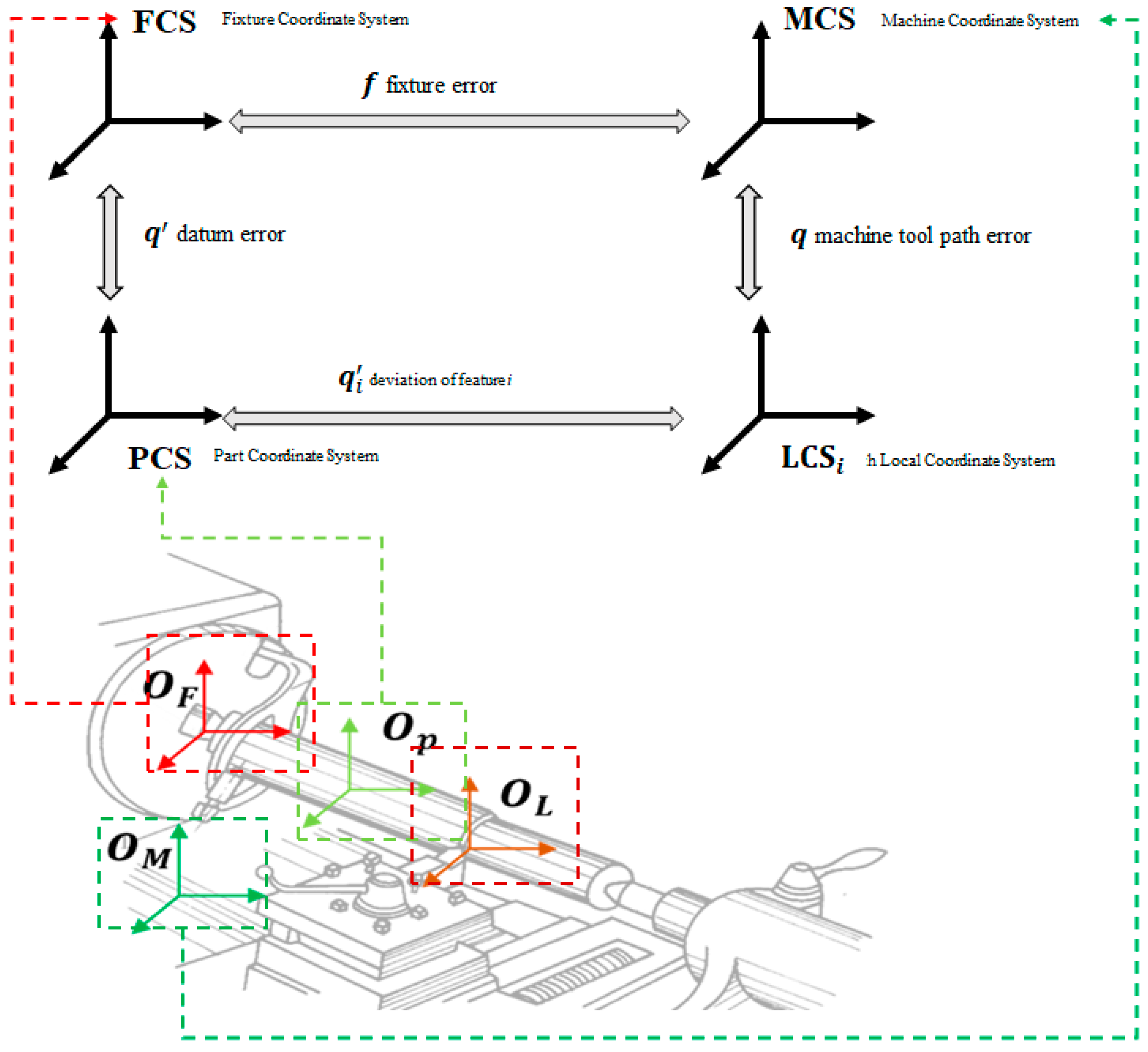
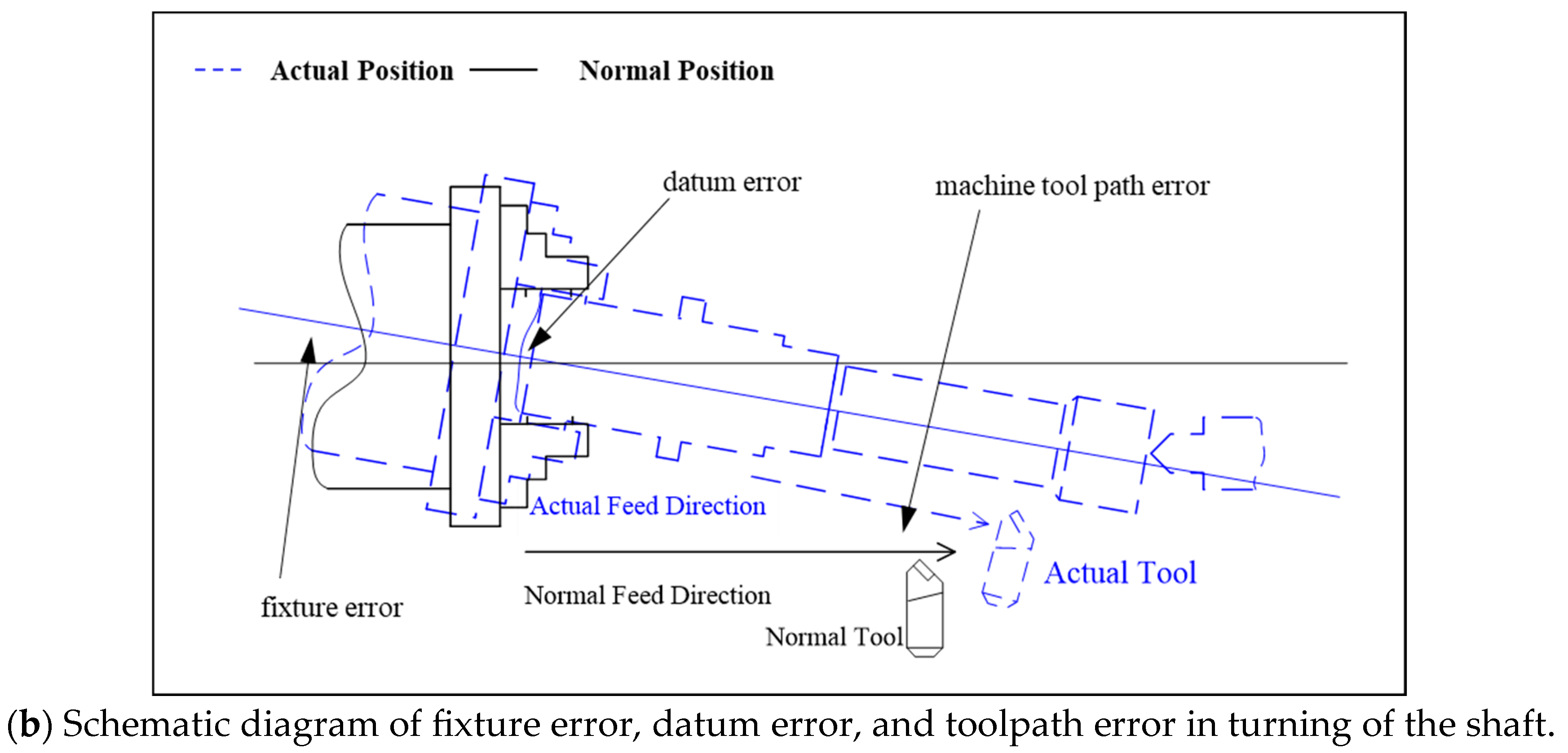
2. Description of Locating Errors in Multistage Turning Processes

EFEs can well describe a machining mechanism where datum and toolpath errors can produce a similar error pattern on machined features as fixture errors. An EFE by toolpath error is shown in Figure 2. Figure 2a represents the workpiece error under the condition of toolpath error. Figure 2b represents the equivalent fixture deviation of toolpath deviation. The machining effect of the workpiece features is the same in both cases.

2.1. Model for Equivalent Error

The EFE model for the overall fixture layout is derived from the SoV model. The machining error is mainly caused by the datum error, the fixture error, and the path error of the machine tool. The deviation of the i -th newly generated feature is described by
q i = F 3 J 1 F 2 q + F 3 J 1 F 1 f + F 4 q
where q i represents the deviation of the feature i in the workpiece; q is the error in the workpiece datum or datum point at this stage; f is fixture manufacturing errors at this stage; q is the path error of the machine tool; J represents the Jacobian matrix; and F 1 ~ F 4 are the matrices used to calculate q i , which are related to the spatial position of the tool-machine fixture-tool-workpiece machining system [12]. The physical meaning and spatial relationship of each parameter are shown in Figure 3.
In the machining process shown in Figure 3, q i is the outer circumference being turned, f is the manufacturing error of the three-jaw chuck, q is the error of the contact datum between the workpiece and the three-jaw chuck fixture, and q is the deviation of the toolpath during tool feed.
As shown in Figure 3, to simplify matters, the fixture coordinate system (FCS) is used interchangeably with the part coordinate system (PCS) in this paper. From Equation (1), it can be seen that the variation of the workpiece is made up of three components:
q d = F 3 J 1 F 2 q
q f = F 3 J 1 F 1 f
q m = F 4 q
where q d , q f and q m are the feature deviations due to datum, fixture, and toolpath errors, respectively.
The equivalent machine toolpath error caused by the datum error can be calculated by solving Equations (2) and (3) as follows:
F 4 q d = F 3 J 1 F 2 q
where q d is equivalent error caused by datum error.
q d = F 4 1 F 3 J 1 F 2 q
The equivalent machine toolpath error caused by the fixture error can be calculated by solving Equations (3) and (4) as follows:
F 4 q f = F 3 J 1 F 1 f
where q f is the equivalent error caused by the fixture error.
q f = F 4 1 F 3 J 1 F 1 f
Considering Equations (4), (6) and (8), the total errors in the equivalent-machine-toolpath-error form can be written as
x = q d + q f + q m
Machined quality, ideally when the error of the machined feature is zero, can be guaranteed by the amount of adjustment of the toolpath.
x = q d + q f + q m + c = 0
Therefore, the amount of adjustment of the toolpath of machine c can be defined by
c = [ q d + q f + q m ]
The toolpath can be adjusted to compensate for these major errors, and the toolpath adjustment amount is c given by Equation (11).

2.2. Model Derivation for Multistage Turning Processes

Due to the difference in the positioning scheme between MMPs for the production of cubic parts and MMPs for the production of rotary parts, F1~F4 in Equation (1) for fabricating cubic workpieces cannot be directly applicable to shaft workpieces. Therefore, F1~F4 in Equation (1) should be derived for MTPs. The four-jaw chuck clamping scheme in turning, an important clamping strategy, is analyzed in this paper. The relationship between the clamping chuck and the parts is shown in Figure 4a. Figure 4b shows that the jaws limit movement along the X, Y, and Z axes and rotation around the X, Y, and Z axes; sufficient clamping force is applied to limit rotation around the Z axis.
Denote n i = n i x n i y n i z T as the device output standard to the surface contact of the i-th locators in the PCS. For simplicity, FCS and PCS are used interchangeably in this paper. The F 1 in [2] can be expressed as
F 1 = [ n 1 T 0 n 6 T ] [ R p T R p T ]
where n i represents the feature’s initial normal vector at the i-th locator and R p is the rotation transformation matrix of the PCS with respect to the FCS.
If the FCS is taken to be the same as the PCS, then R p will be an identified matrix. Therefore, Equation (12) becomes Equation (13).
F 1 = [ n 1 T 0 n 6 T ]
By knowing the surface normal at the feature contact, the k -th locator in the PCS n i k , the position of the point contacting the k -th locator in the PCS t i k and the transformation matrix from the 0PCS to the LCS expressed in PCS, H 0 i , F 2 can be easily derived.
The total deviation of the PCS, with respect to the GCS, due to the datum error and the fixture error is denoted by q p = q p α q p β q p γ q p x q p y q p z T , and the corresponding HTM of q p can be written as
H ( q p ) = [ 1 q p γ q p β q p x q p γ 1 q p α q p y q p β q p α 1 q p z 0 0 0 1 ]
where q p α , q p β and q p γ are the three small orientational deviations of q p ; q p x , q p y and q p z are three small translational deviations of q p .
The toolpath error may be represented by q i . The deviation of HTM from 0LCS expressed in 0PCS to LCS is caused by the machine toolpath error. The machine toolpath error is denoted by q i = e α e β e γ e x e y e z T , and then, the corresponding HTM of q i can be written as
H ( q i ) = [ 1 e γ e β e x e γ 1 e α e y e β e α 1 e z 0 0 0 1 ]
where e α , e β and e γ are the three small orientational deviations of q i and e x , e y and e z are three small translational deviations of q i .
General fixture layouts can be handled with this method. In this paper, an or-thogonal fixture layout case is given for simplicity. For a common 3-2-1 fixture setup, the procedure presented can be used to study the datum-induced error. H 0 i is HTM from the 0PCS to the LCS expressed in PCS. When the position parameters a x , a y and a z are given, H 0 i can be written as follows:
H 0 i = [ 1 0 0 a x 0 1 0 a y 0 0 1 a z 0 0 0 1 ]
The final deviation of the newly created feature in the PCS can be obtained by the following identity, given the deviation of the PCS from the GCS due to the datum and fixture errors and the deviation of the cutting tool from the GCS due to the machine geometry error:
H ( q i ) = ( H 0 i ) H ( q p ) 1 ( H 0 i ) H ( q i )
Substituting Equations (14)–(16) into the right-side of Equation (17) and ignoring the small second order values give the result of the approximation of Equation (17) as
H ( q i ) = [ 1 q p γ e γ e β q p β e x q p x + q p γ a y q p β a z q p γ + e γ 1 q p α e α e y q p y + q p α a z q p γ a x e β + q p β q p α + e α 1 e z q p z + q p β a x q p α a y 0 0 0 1 ]
Rewriting Equation (18) as column vectors gives
q i = [ e x q p x + q p γ a y q p β a z e y q p y + q p α a z q p γ a x e z q p z + q p β a x q p α a y e α q p α e β q p β e γ q p λ ]
By solving Equation (19), the source errors and corresponding coefficient matrices can be divided. Then, Equation (20) can be obtained:
q i = [ e x q p x + q p γ a y q p β a z e y q p y + q p α a z q p γ a x e z q p z + q p β a x q p α a y e α q p α e β q p β e γ q p γ ] = F 3 [ q p x q p y q p z q p α q p β q p γ ] + F 4 [ e x e y e z e α e β e γ ]
where F 3 is the coefficient matrix of the deviation due to the errors of the datum and the fixture and F 4 is the coefficient matrix of the machine toolpath error. F 3 and F 4 are expressed as Equations (21) and (22), respectively.
F 3 = [ 1 0 0 0 a z a y 0 1 0 a z 0 a x 0 0 1 a y a x 0 0 0 0 1 0 0 0 0 0 0 1 0 0 0 0 0 0 1 ]
F 4 = [ 1 0 0 0 0 0 0 1 0 0 0 0 0 0 1 0 0 0 0 0 0 1 0 0 0 0 0 0 1 0 0 0 0 0 0 1 ]
This model can predict the machining error for shaft workpieces with a four-jaw chuck fixturing scheme in the turning process.

3. Case Study

Two experiments will be conducted in Section 3.1 to validate the proposed model. Then, A process for simulating EFE compensation for machining over five workpieces is illustrated in Section 3.2.
This section verifies the accuracy and effectiveness of the model through prediction and compensation. In Section 3.1, error prediction was conducted for a single feature point and multiple sampling points. In Section 3.2, existing and proposed error-compensation methods were compared.

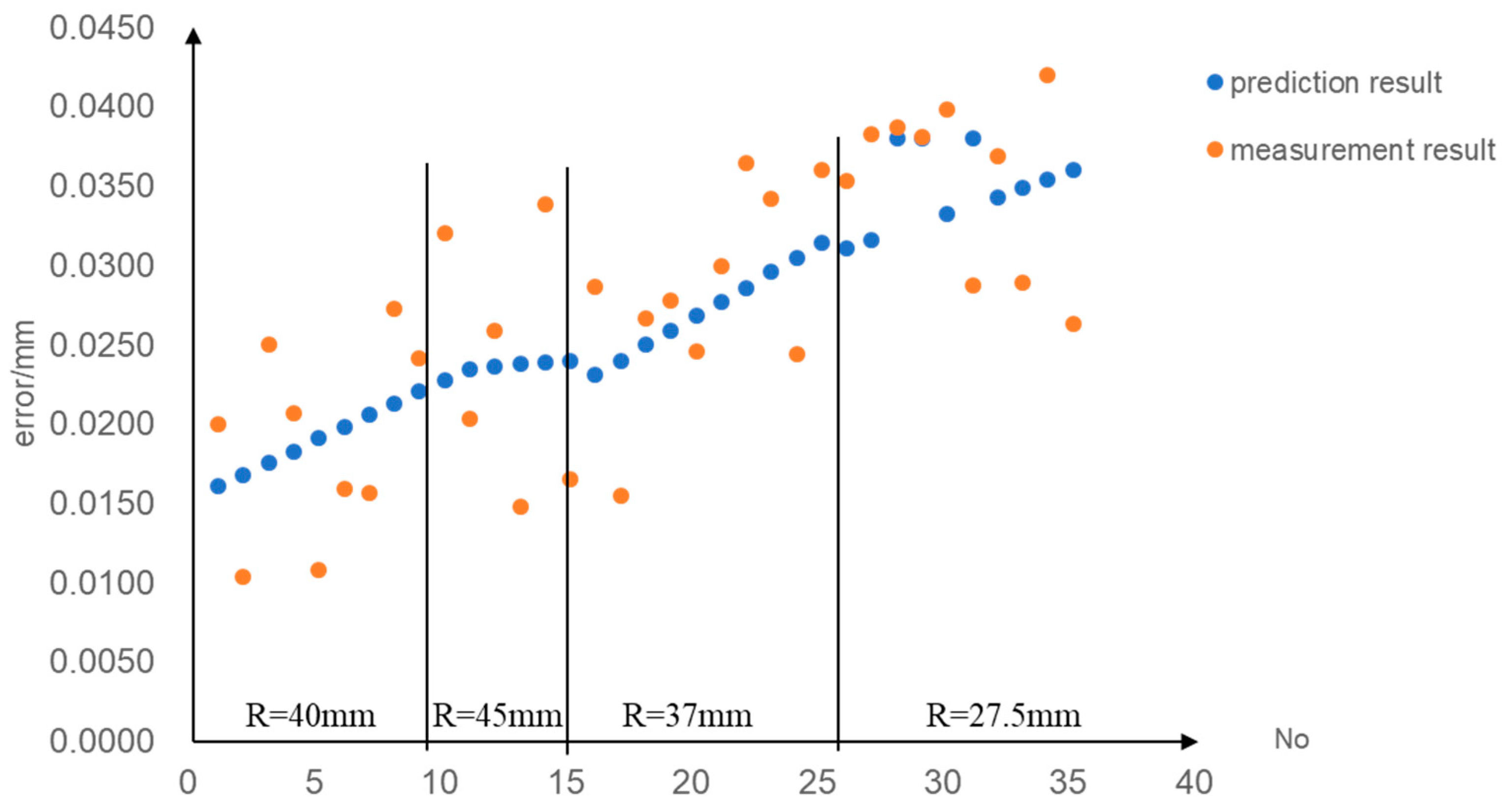
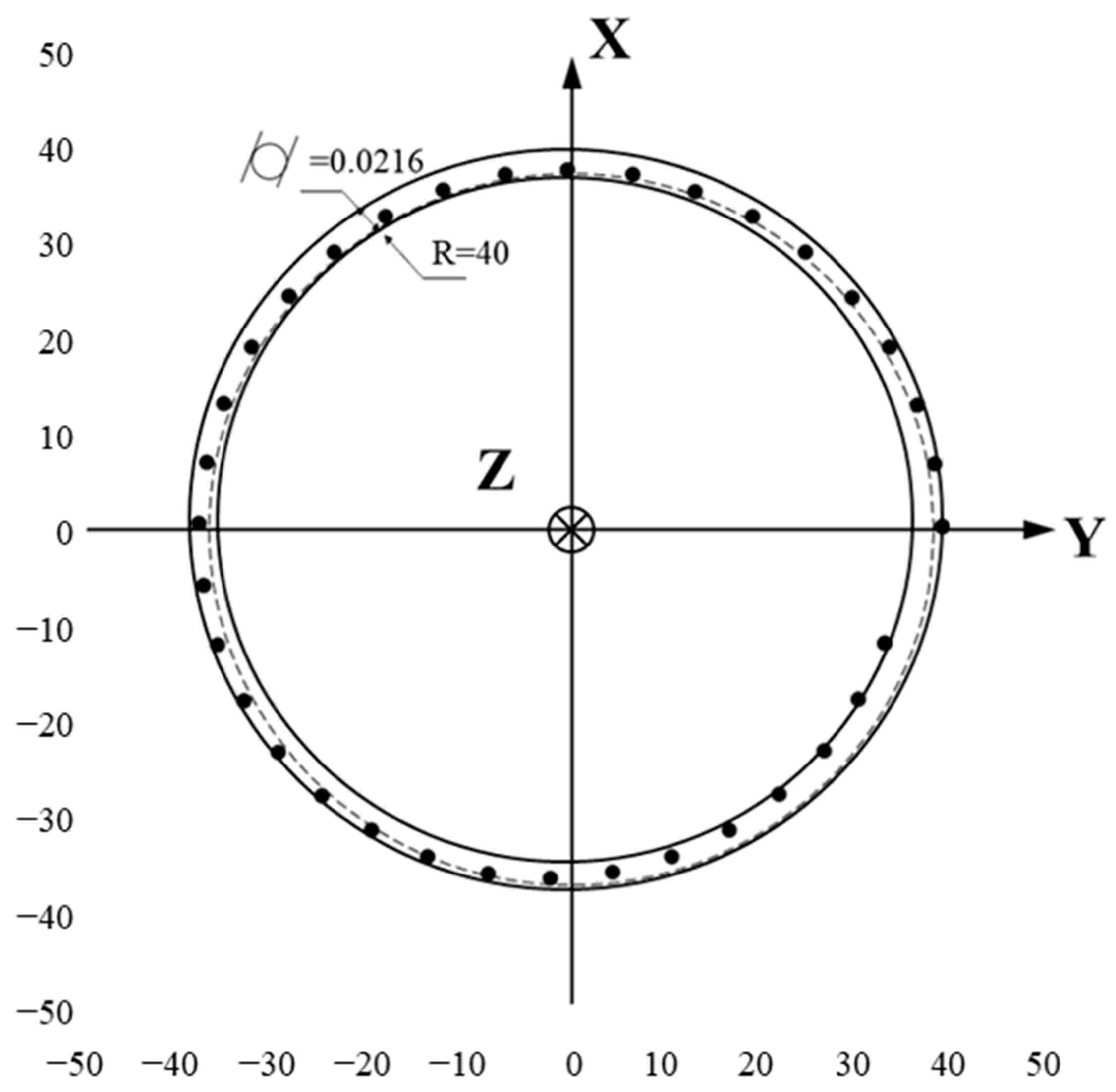
3.1. Error Prediction Simulation

A machining process of stepped shaft was used to simulate the proposed variation model. The key features of this shaft are shown in Figure 5a. Under the clamping method of Figure 5a, the fixture error, datum error, and toolpath error when machining multistage shaft parts are shown in Figure 5b. Figure 4b shows the location scheme of the machining process. Feature 2 will be machined under this locating scheme.
The PCS is taken to be the same as the FCS in this paper for the sake of simplicity. The nominal positions and orientations of these features with respect to the PCS are listed in Table 1.
In the actual processing and production process, datum error q and fixture locator error f are measured before the workpiece is clamped and positioned. By analyzing the contact position between the part and the chuck, the nominal coordinates of the position point are determined. The nominal coordinates of the positioning point in this experiment are shown in Table 1. The deviation of each positioning point is determined through three-coordinate detection, and datum error q and fixture locator error f are determined through coordinate-system fitting. For the detection of the machine toolpath error, the offline-tool-setting instrument is used to detect the tool wear and actual parameters, so as to determine the nominal coordinate system of the tool when the toolpath has no deviation. The actual toolpath and the actual coordinate system of the tool are obtained through the online-setting-instrument detection, and the toolpath deviation is obtained through comparison. The detection of the machine toolpath error is shown in Figure 6.
The nominal distance from feature 2 to PCS is 685 mm. Feature 2 is machined without the error-compensation strategy. The machining error predicted by the proposed model is −0.25 mm. The actual distance predicted is 685.25 mm.
Take ∅44.85 for example; the designed radius is 44.85 mm. The machine toolpath error q is set to q = 0.5 0 0 0 0 0 T . The fixture locator error is f = 0 0 0 0 0 0 T and the datum error is also set to zero. Feature 2 is machined without the error-compensation strategy. The machining error predicted by the proposed model is 0.5 mm. Then, the actual radius is predicted to be 45.35 mm.
Based on the error-transfer accumulation model of feature points within the process, by sampling feature points on different diameter step axes, the error distribution of the step axis on the busbar can be fitted, which can be used to evaluate geometric tolerances, such as coaxiality and cylindricity. The geometric dimensions and tolerance requirements of the stepped shaft selected in this article are shown in Figure 7a, and its simplified model is shown in Figure 7b.
In this experiment, the type of machine is the horizontal turning center DOOSAN PUMA 4005L; the cutting tool of the experiment is a carbide-tipped lathe tool; and the machined material of the shaft is 20CrMnMo steel. The machining parameters are as follows: cutting velocity V C = 150 m/min, feed rate f = 0.15 mm/r, and cutting depth a P = 0.2 mm.
Take a point every 22.5 mm within the range of Z = 0~225 mm and Y = 40 mm, with a total of 10 points numbered 1~10. Take a point every 4.1 mm within the range of Z = −225~−245 mm. Y = 45 mm, with a total of 5 points numbered 11~15. Take a point every 27.65 mm within the Z = −245.5~−522 mm, Y = 37 mm interval, totaling 10 points numbered 16–25. Within the range of Z = −522~−685 mm and Y = 27.5 mm, a Z value is taken every 16.3 mm, with a total of 10 points numbered 26~35. The predicted results for these experiments are listed in Table 2.
After the machining experiment was completed, the error of each sampling point was measured using the CMM. In this paper, the GLOBAL S 09.15.08—Blue Bridge Coordinate Measuring Machine was selected with a resolution of 1.2 μm. The measurement results are shown in Table 2.

3.2. Experimental Validation of Compensation

Table 3 and Table 4 show the inputs of the second condition for the datum error and its corresponding EFE, the jig error and its corresponding EFE, and the machine toolpath error. Take the first experiment, for example, where the datum-error and toolpath-error EFEs are calculated to be Δ d = 0.02 0.02 0.02 0.03 0.03 0 T mm and Δ f = 0 0 0 0 0 0.02 T , respectively. With knowledge of these EFEs, the total EFE can be calculated as Δ d + Δ m + f = 0.04 0.04 0.04 0.06 0.06 0.02 T . The adjustment of the locators to counteract the total errors can be calculated using Equation (19). After determining the fixture position adjustment Δ c 2 1 = 0.04 0.04 0.04 0.06 0.06 0.02 T , feature 2 was machined.
The machining error predicted by the KA method was −0.02 mm in the first experiment without compensation. The result of the measurement by CMM was −0.028 mm. Between prediction and measurement, there were small deviations. After compensating for errors using the proposed EFE model, the result of measurement in the second experiment was −0.006 mm. Without compensation, the primary causes of machining errors were the datum error, the fixture error, and the machine toolpath error. However, the machining error can be significantly reduced if the EFE-compensation strategy is performed before machining.

3.3. Discussion

3.3.1. Model Accuracy

In Section 3.1, the accuracy of the model was verified through theoretical analysis and model derivation, and then, samples were taken on the busbars of stepped axes with different radii. The CMM measurement results and the predicted results for these two experiments are listed in Table 2. The predicted and measured values of radial errors on the YOZ section in the direction of the workpiece axis are shown in Figure 8. As the distance between the sampling point and the chuck clamping position increases, the radial error of the workpiece gradually increases, which is consistent with the remote amplification effect of the error. From a theoretical perspective, the accuracy of the model has been proven. Comparing the predicted values with the measured values, the trend of the two is consistent, proving the accuracy of the model from a measurement perspective.
To quantitatively describe the accuracy of the model’s prediction bias, the mean relative error (MRE) can be evaluated by calculating once at each step. The calculation results are shown in Table 5. By analyzing the MRE, it can be demonstrated that the model has high accuracy.

3.3.2. Model Application

Through the model, the cylindricity of shaft parts can be obtained. Taking a radius of r = 40 mm as an example, the sampling results are projected along the axis, as shown in Figure 9. By using the predicted deviation values of the model or the measured deviation values of CMM Δx and Δy of the multistep rotary shaft in each section and combining the nominal values of each feature point, the extreme difference values of the feature points along the axial direction can be calculated, and according to the definition of cylindricity, the predicted cylindricity in the case of r = 40 mm can be found to be 0.0216 mm. In addition, the fitting center of the cross section can be obtained by four sampling points on the same cross section, thus predicting the coaxiality, positional tolerance, and other geometric tolerances of the workpiece. Furthermore, the method proposed in this article lays the foundation for global morphology simulation of multistep axis machining.

4. Conclusions

  • For the multistep rotary shaft, the final dimensional accuracy is mainly affected by datum errors, fixture errors, and machine toolpath errors. In this paper, an EFE method is proposed to solve the problem of equating the error sources of fixture error, datum error, and toolpath error in the rotary machining of multistep axes by combining them with the theory of equivalent error. By equating each error source to the toolpath error, the toolpath can be adjusted in real time to compensate for the multi-attitude of the workpiece during machining.
  • This article demonstrates the accuracy of the prediction model and the effectiveness of the compensation model through experiments. The accuracy of the model was demonstrated by comparing the predicted values with the actual measured values for multistage stepped axis turning, and the proposed compensation method was demonstrated to be effective in reducing errors in workpiece features during machining. By extending the prediction model from single-point prediction to multi-point prediction, it is possible to make predictions for form tolerance parameters, such as cylindricity of shaft parts.
  • The model presented in this article provides a framework for the prediction and compensation of machining errors for rotary-type parts. To increase the generalizability of the model, flexible deformations, such as holding deformation, tool letting deformation, cutting forces, thermal deformation, and residual stress deformation, can be introduced into the framework for error compensation of annular thin-walled parts, such as aero-engine magazines and flame cartridges. These potential works using EFE models will be continued and reported in the future.

Author Contributions

Conceptualization, S.L.; methodology and software, A.T. and X.D.; writing—original draft preparation, A.T. and X.D.; writing—review and editing, A.T. and X.D. and S.J.; supervision, S.L. and S.J.; funding acquisition, S.L. and S.J. All authors have read and agreed to the published version of the manuscript.

Funding

This work was partially supported by the National Natural Science Foundation of China (Grant No. 51975369), the JCKY Research Program (2021110B048), and the Startup Fund for Young Faculty at SJTU (SFYS at SJTU).

Data Availability Statement

Not applicable.

Acknowledgments

Not applicable.

Conflicts of Interest

The authors declare no conflict of interest.

References

  1. Ramesh, R.; Mannan, M.A.; Poo, A.N. Error compensation in machine tools—A review: Part I: Geometric, cutting-force induced and fixture-dependent errors. Int. J. Mach. Tools Manuf. 2000, 40, 1235–1256. [Google Scholar] [CrossRef]
  2. Cai, W.; Hu, S.J.; Yuan, J.X. A Variational Method of Robust Fixture Configuration Design for 3-D Workpieces. J. Manuf. Sci. Eng. 1997, 119, 593–602. [Google Scholar] [CrossRef]
  3. Yu Wang, M. Tolerance analysis for fixture layout design. Assem. Autom. 2002, 22, 153–162. [Google Scholar] [CrossRef]
  4. Jin, S.; Liu, S.; Zhang, X.; Chen, K. A unified prediction model of 3D surface topography in face milling considering multi-error sources. Int. J. Adv. Manuf. Technol. 2019, 102, 705–717. [Google Scholar] [CrossRef]
  5. Chen, K.; Liu, S.; Tian, A.; Mo, W.; Jin, S. Interaction analysis of geometric tolerance of multi-axis machine tools based on kinematic Jacobian-Torsor model. Proc. Inst. Mech. Eng. Part B-J. Eng. Manuf. 2023, 237, 240–249. [Google Scholar] [CrossRef]
  6. Qing, G.H.; Wang, M.M.; Lin, F. Fixturing Layout Optimal Method Based on TOPSIS and MOEA/D. Comput. Integr. Manuf. Syst. 2022, 1–24. Available online: http://kns.cnki.net/kcms/detail/11.5946.TP.20220613.0842.004.html (accessed on 1 April 2023).
  7. Zmarzły, P. Analysis of Technological Heredity in the Production of Rolling Bearing Rings Made of AISI 52100 Steel Based on Waviness Measurements. Materials 2022, 15, 3959. [Google Scholar] [CrossRef]
  8. Zheng, A.Q.; Ji, F.F.; Sun, Q.; Liu, Z.Q. Experimental study on optimization of cutting parameters for fixed pitch propelle. Manuf. Technol. Mach. Tool 2019, 689, 168–172. [Google Scholar]
  9. Huang, Q.; Zhou, N.; Shi, J. Stream of Variation Modeling and Diagnosis of Multi-Station Machining Processes. In Proceedings of the ASME International Mechanical Engineering Congress and Exposition, Orlando, FL, USA, 5–10 November 2000; Volume 11, pp. 81–88. [Google Scholar]
  10. Djurdjanovic, D.; Ni, J. Linear state space modeling of dimensional machining errors. Trans. NAMRI/SME 2001, 29, 541–548. [Google Scholar]
  11. Zhou, S.; Huang, Q.; Shi, J. State space modeling of dimensional variation propagation in multistage machining process using differential motion vectors. IEEE Trans. Robot. Autom. 2003, 19, 296–309. [Google Scholar] [CrossRef]
  12. Loose, J.P.; Zhou, S.; Ceglarek, D. Kinematic analysis of dimensional variation propagation for multistage machining processes with general fixture layouts. IEEE Trans. Autom. Sci. Eng. 2007, 4, 141–152. [Google Scholar] [CrossRef]
  13. Abellan-Nebot, J.V.; Liu, J.; Romero, F. State space modeling of variation propagation in multistation machining processes considering machining-induced variations. J. Manuf. Sci. Eng.-Trans. ASME 2012, 134, 021002. [Google Scholar] [CrossRef]
  14. Abellan-Nebot, J.V.; Liu, J. Variation propagation modeling for multi-station machining processes with fixtures based on locating surfaces. Int. J. Prod. Res. 2013, 51, 4667–4681. [Google Scholar] [CrossRef]
  15. Jia, F.; Jiang, P.Y.; Liu, D.Y.; Zheng, M. Error propagation control method for multistage batches machining processes of blades. Comput. Integr. Manuf. Syst. 2012, 18, 76–86. [Google Scholar]
  16. Zeng, W.; Fang, F.; Ma, X. On-position measurement method for position-error compensation in machining. Int. J. Precis. Eng. Manuf. 2021, 22, 1179–1189. [Google Scholar] [CrossRef]
  17. Du, Z.C.; Ge, G.Y.; Xiao, Y.K.; Feng, X.B.; Yang, J.G. Modeling and Compensation of Comprehensive Errors for Thin-walled Parts Machining Based on On-machine Measurement. Int. J. Adv. Manuf. Technol. 2021, 115, 11–12. [Google Scholar] [CrossRef]
  18. Deng, M.; Li, H.; Xiang, S.; Liu, P.; Feng, X.; Du, Z.; Yang, J. Geometric errors identification considering rigid-body motion constraint for rotary axis of multi-axis machine tool using a tracking interferometer. Int. J. Mach. Tools Manuf. 2020, 158, 103625. [Google Scholar] [CrossRef]
  19. Pan, S.L.; Zhao, G.B. A real-time compensation method for thermal deformation of high speed machine spindle based on SINUMERIK CNC system. Manuf. Technol. Mach. Tool 2021, 707, 119–123. [Google Scholar]
  20. Ravichandra, R.; Manjunath, P.G.C.; Chate, G.R.; Deepak, L.; Avinash, L.; Khaled, G.; Pimenov, D.Y. Coaxiality error analysis and optimization of cylindrical parts of CNC turning process. Int. J. Adv. Manuf. Technol. 2022, 120, 6617–6634. [Google Scholar]
  21. Zhu, M.; Ge, G.; Feng, X.; Du, Z.; Yang, J. A novel error compensation method for multistage machining processes based on differential motion vector sets of multiple contour points. J. Manuf. Sci. Eng. 2021, 143, 061010. [Google Scholar] [CrossRef]
  22. Liu, C.; Jin, S.; Wang, D.; Luo, Z.; Yu, J.; Zhou, B.; Yang, C. Constrained oversampling: An oversampling approach to reduce noise generation in imbalanced datasets with class overlapping. IEEE Access 2020, 10, 91452–91465. [Google Scholar] [CrossRef]
  23. Wei, X.Y.; Chen, Y.C.; Miao, E.M.; Feng, X.G.; Pan, Q.S. Application of principal component algorithm in spindle thermal error modeling of CNC machine tools. Opt. Precis. Eng. 2021, 29, 2649–2660. [Google Scholar] [CrossRef]
  24. Okafor, A.C.; Ertekin, Y.M. Derivation of machine tool error models and error compensation procedure for three axes vertical machining center using rigid body kinematics. Int. J. Mach. Tools Manuf. 2000, 40, 1199–1213. [Google Scholar] [CrossRef]
  25. Yang, J.; Yuan, J.; Ni, J. Thermal error mode analysis and robust modeling for error compensation on a CNC turning center. Int. J. Mach. Tools Manuf. 1999, 39, 1367–1381. [Google Scholar] [CrossRef]
  26. Wu, H.; Turyagyenda, G.; Yang, J.G. Modeling and Real-time Compensation of Cutting Force-induced Errors on NC Turning Center. In Key Engineering Marterials; Advances in Machining & Manufacturing Technology VIII; Trans Tech Publications Ltd.: Zurich, Switzerland, 2006; Volume 315–316. [Google Scholar]
  27. Wang, H.; Huang, Q.; Katz, R. Multi-operational machining processes modeling for sequential root cause identification and measurement reduction. Trans. ASME J. Manuf. Sci. Eng. 2005, 127, 512–521. [Google Scholar] [CrossRef]
  28. Wang, H.; Huang, Q. Error cancellation modeling and its application to machining process control. IIE Trans. 2006, 38, 355–364. [Google Scholar] [CrossRef]
  29. Yang, F.; Xing, Y.; Li, X. A comprehensive error compensation strategy for machining process with general fixture layouts. Int. J. Adv. Manuf. Technol. 2020, 107, 2707–2717. [Google Scholar] [CrossRef]
  30. Du, S.C.; Yao, X.F.; Huang, D.L.; Wang, M. Three-dimensional variation propagation modeling for multistage turning process of rotary workpieces. Comput. Ind. Eng. 2015, 82, 41–53. [Google Scholar] [CrossRef]
  31. Du, S.; Yao, X.; Huang, D. Engineering model-based Bayesian monitoring of ramp-up phase of multistage manufacturing process. Int. J. Prod. Res. 2015, 53, 4594–4613. [Google Scholar] [CrossRef]
  32. Wang, K.; Du, S.; Xi, L. Three-Dimensional Tolerance Analysis Modelling of Variation Propagation in Multi-stage Machining Processes for General Shape Workpieces. Int. J. Precis. Eng. Manuf. 2020, 21, 31–44. [Google Scholar] [CrossRef]
Figure 1. Multistep rotary shaft of high-speed motorized spindle.
Machines 11 00561 g001
Figure 2. EFE caused by machine toolpath error.
Machines 11 00561 g002
Figure 3. Spatial distribution of turning errors in shaft parts.
Machines 11 00561 g003
Figure 4. Example of fixing and positioning of rotating parts.
Machines 11 00561 g004
Figure 5. Characteristics and clamping method of the test pieces.
Machines 11 00561 g005aMachines 11 00561 g005b
Figure 6. The measurement of the machine toolpath error.
Machines 11 00561 g006
Figure 7. Multistep rotary shaft engineering drawing.
Machines 11 00561 g007
Figure 8. The trend of the CMM measurement results and the predicted results.
Machines 11 00561 g008
Figure 9. Cylindricity error with R = 40 mm.
Machines 11 00561 g009
Table 1. Nominal positions and orientations of key features in FCS.
Name of FeaturePositionsOrientations ω i R
L 1 [−45,0,0][−1,0,0][−π/2,−π/2,0]
L 2 [−45,0,−60][−1,0,0][−π/2,−π/2,0]
L 3 [−45,−45,−30][−1,0,0][−π/2,−π/2,0]
L 4 [0,45,0][0,1,0][−π/2,0,π/2]
L 5 [0,45,−60][0,1,0][−π/2,0,π/2]
L 6 [0,0,0][0,0,1][0,0,π]
Machined Feature[0,44.85,−685][1,0,0][π/2,0,π]
Table 2. Predicted results and CMM measurement results for sampling point.
No.Normal Position
(x, y, z)
(mm, mm, mm)
Feature-Point Predicted Error
(Δx, Δy, Δz)
(mm, mm, mm)
CMM Measurement
(Δx, Δy, Δz)
(mm, mm, mm)
1 (0, 40, −22.5)(0.0309, 0.0161, 0.001)(0.0314, 0.018, −0.0003)
2(0, 40, −45)(0.0259, 0.0168, 0.001)(0.0264, 0.0153, 0.0007)
3(0, 40, −67.5)(0.0208, 0.0176, 0.001)(0.0205, 0.02, 0.0027)
4(0, 40, −90)(0.0158, 0.0183, 0.001)(0.0161, 0.0196, −0.0004)
5(0, 40, −112.5)(0.0107, 0.0191, 0.001)(0.0101, 0.0167, 0.0024)
6(0, 40, −135)(0.0056, 0.0198, 0.001)(0.0035, 0.0208, 0.0008)
7(0, 40, −157.5)(0.0006, 0.0206, 0.001)(0.0009, 0.0204, −0.0002)
8(0, 40, −180)(−0.0045, 0.0213, 0.001)(−0.0049, 0.0229, 0.0023)
9(0, 40, −202.5)(−0.0096, 0.0221, 0.001)(−0.0092, 0.0207, 0.0014)
10(0, 40, −225)(−0.0146, 0.0228, 0.001)(−0.0154, 0.0239, 0.003)
11(0, 45, −229.1)(−0.0146, 0.0235, −0.0001)(−0.0133, 0.0249, 0.0001)
12(0, 45, −233.2)(−0.0155, 0.0236, −0.0001)(−0.013, 0.0244, −0.0006)
13(0, 45, −237.3)(−0.0165, 0.0238, −0.0001)(−0.015, 0.0234, 0.0007)
14(0, 45, −241.4)(−0.0174, 0.0239, −0.0001)(−0.0177, 0.0241, −0.0008)
15(0, 45, −245.5)(−0.0183, 0.024, −0.0001)(−0.016, 0.025, −0.0012)
16(0, 37, −273.15)(−0.0192, 0.0231, 0.0017)(−0.0186, 0.0219, 0.0025)
17(0, 37, −300.8)(−0.0255, 0.024, 0.0017)(−0.0275, 0.0249, 0.0002)
18(0, 37, −328.45)(−0.0317, 0.025, 0.0017)(−0.0304, 0.0227, 0.0013)
19(0, 37, −356.1)(−0.0379, 0.0259, 0.0017)(−0.0377, 0.0238, 0.002)
20(0, 37, −383.75)(−0.0441, 0.0268, 0.0017)(−0.0462, 0.0271, 0.0035)
21(0, 37, −411.4)(−0.0503, 0.0277, 0.0017)(−0.0526, 0.026, 0.0029)
22(0, 37, −439.05)(−0.0566, 0.0286, 0.0017)(−0.0555, 0.0267, 0.0024)
23(0, 37, −466.7)(−0.0628, 0.0296, 0.0017)(−0.0641, 0.0286, 0.0028)
24(0, 37, −494.35)(−0.069, 0.0305, 0.0017)(−0.0681, 0.03, 0.0019)
25(0, 37, −522)(−0.0752, 0.0314, 0.0017)(−0.0734, 0.0301, 0.0024)
26(0, 27.5, −538.3)(−0.0814, 0.0311, 0.0038)(−0.0797, 0.0332, 0.003)
27(0, 27.5, −554.6)(−0.0851, 0.0316, 0.0038)(−0.0866, 0.0307, 0.006)
28(0, 27.5, −570.9)(−0.0888, 0.0322, 0.0038,0)(−0.0864, 0.0018, 0.0013)
29(0, 27.5, −587.2)(−0.0925, 0.0327, 0.0038,0)(−0.09, 0.0052, −0.0018)
30(0, 27.5, −603.5)(−0.0961, 0.0332, 0.0038)(−0.0962, 0.0319, 0.0035)
31(0, 27.5, −619.8)(−0.0998, 0.0338, 0.0038,0)(−0.1007, 0.0018, 0.0007)
32(0, 27.5, −636.1)(−0.1035, 0.0343, 0.0038)(−0.1054, 0.0343, 0.0045)
33(0, 27.5, −652.4)(−0.1071, 0.0349, 0.0038)(−0.1054, 0.0325, 0.0039)
34(0, 27.5, −668.7)(−0.1108, 0.0354, 0.0038)(−0.1121, 0.0332, 0.0017)
35(0, 27.5, −685)(−0.1145, 0.036, 0.0038)(−0.1169, 0.037, 0.0032)
Table 3. Datum error and corresponding EFE.
No.Datum ErrorEFE
L 1 0 0.018 0 0 0 0 T [ 0.018 0.018 0.018 0 0 0 ] T
L 2 0 0.018 0 0 0 0 T [ 0.013 0.0329 0.0329 0 0 0 ] T
L 3 0 0.018 0 0 0 0 T [ 0.0086 0.0174 0.0057 0 0 0 ] T
L 4 0 0.018 0 0 0 0 T [ 0.01 0.01 0.01 0 0 0 ] T
L 5 0 0.018 0 0 0 0 T [ 0.0316 0.0603 0.0372 0 0 0 ] T
Table 4. Fixture error and corresponding EFE.
No.Fixture ErrorEFE Error
L 1 0 0.018 0 0 0 0 T [ 0.018 0.018 0.018 0 0 0 ] T
L 2 0 0.018 0 0 0 0 T [ 0.013 0.0329 0.0329 0 0 0 ] T
L 3 0 0.018 0 0 0 0 T [ 0.0086 0.0174 0.0057 0 0 0 ] T
L 4 0 0.018 0 0 0 0 T [ 0.01 0.01 0.01 0 0 0 ] T
L5 0 0.018 0 0 0 0 T [ 0.0316 0.0603 0.0372 0 0 0 ] T
Table 5. MRE of individual radii.
No.R/mmMRE
1402.78%
2452.85%
33712.12%
427.56.53%
Disclaimer/Publisher’s Note: The statements, opinions and data contained in all publications are solely those of the individual author(s) and contributor(s) and not of MDPI and/or the editor(s). MDPI and/or the editor(s) disclaim responsibility for any injury to people or property resulting from any ideas, methods, instructions or products referred to in the content.

