1. Introduction
In recent years, there has been growing interest in remanufacturing as a research topic, especially in the context of sustainability and green engineering. Remanufacturing is the process of restoring used products to a condition that is equal to or better than their original state, thereby minimizing waste and reducing carbon footprints. The process involves various steps, such as sorting, disassembly, cleaning, inspection, and rebuilding [
1,
2]. Disassembly of fitted components, particularly interference-fitted ones, is a critical step in the remanufacturing process. Disassembly is essential for product recovery and is the primary source of data related to remanufacturing operations. Interference fits, also referred to as friction fits or press-fits, are commonly employed in mechanical joints due to their cost-effectiveness and simple design. These joints are particularly useful for cylindrical components in various mechanical systems because of their precise radial alignment [
3]. Torque-transmitting bearings, which are widely used in heavy machinery, locomotives, and electrical hardware systems [
4], are some of the applications of press-fit joints. Disassembly of interference joints is a crucial stage in the disassembly process. However, due to the complexity of the mating parts, it can be challenging to remove them without causing plastic deformation, scratches, and adhesion. These types of friction damage can adversely affect the success of the remanufacturing process.
Remanufacturing, a process aimed at maintaining the original shape and/or output of a component, is in contrast to recycling. Successful remanufacturing depends on the integrity of the parts during disassembly, which is a crucial step. Unfortunately, disassembly is mostly performed manually with hand tools, as automated tools are expensive [
5], leading to increased labor costs and limiting the applicability for complex products [
6]. For example, disassembling shaft-and-hub joints often requires applying torque and axial loading, which can cause deformations and increase separation difficulty. Additionally, the loss of contact between the shaft and hub increases susceptibility to fretting wear [
7]. Earlier research by Radi et al. developed a mathematical model validated by finite element analysis (FEA) to investigate the bending moment of the detachment of shaft-hub press-fits [
8]. Hammond et al. demonstrated in another study that disassembly was a significant concern for remanufacturers, with corrosion being the most serious concern during disassembly [
9]. Corrosion can cause sticking or bonding of the parts, making disassembly difficult, particularly after prolonged storage of up to 30 years, which can initiate adhesive and corrosion bonds. This increases the extraction force needed, as the coefficient of friction (COF) increases [
10]. The required disassembly power for rusted joints could be twice that of non-corroded ones [
11].
Permanent fastening is considered a significant challenge during disassembly processes, second only to corrosion. Breaking up interference fits can be a difficult process that often results in frictional damage and plastic deformation. The amount of force required for removal is directly related to the extent of the damage caused [
2]. To overcome this problem, non-destructive disassembly (ND) methods have been proposed to prevent damage to components [
9]. A study by Mok et al. showed that minimal extraction force was one of the most critical characteristics for easy disassembly of mechanical parts [
12]. Reducing the extraction force is crucial as it allows the application of simple tools and techniques and minimizes frictional damage, thereby reducing refurbishing costs. However, interference fits, also known as permanent or semi-permanent fittings, are often considered impossible-to-disassemble [
13]. When conducting non-destructive disassembly (ND), it is crucial to maintain the loading capacity of interference fits while avoiding surface damage, such as bulges or furrows. Disassembly should be carried out in a manner that avoids plastic and thermal strains, as plastic strain can result in permanent deformation of the structure, which can ultimately affect the strength and ductility of the part [
14]. When a part is subjected to plastic strain, it becomes more susceptible to necking, which significantly reduces the life cycle of the remanufactured part [
7]. Zhou et al. [
2] analyzed plastic strains and found a strong correlation between surface damages and extraction force. Consequently, significant efforts have been made to reduce extraction forces during disassembly processes.
Currently, various methods are used to ease the extraction of interference fits, such as cold contraction, thermal expansion, and injection of pressurized oil [
14]. The primary goal of these methods is to minimize contact pressure and reduce the force required for disassembly. Two primary approaches have been studied: thermal disassembly and vibration-assisted disassembly. Thermal disassembly has several advantages, including reducing surface damage, being highly effective for coatings in post-processing and refurbishing, and being suitable for automated disassembly. Wang et al. [
15] explored the use of liquid nitrogen to weaken a sleeved interference fit. The sleeved joints allowed the liquid nitrogen to pass through and create radial shrinkage. Their findings showed that this technique significantly reduced the radial and hoop stresses, which, in turn, reduced the disassembly force required. However, the study did not investigate thermal strains and plastic deformation.
Shaheen et al. [
16] conducted a study to investigate the thermal behavior of high-strength stainless steel bolt assemblies at elevated temperatures. They observed that the tensile strength of the assemblies gradually decreased with increasing temperature up to 300 °C, followed by a much sharper drop. Beyond 300 °C, the assemblies could not retain much of their original strength even after cooling. It is crucial to maintain the original strength of the parts after thermal expansion to ensure acceptable performance after remanufacturing. Sun et al. [
17] also studied the behavior of S235 steel under an elevated temperature and suggested that thermal plastic strains significantly increased at temperatures above 200 °C. In another study, Bengeri et al. [
18] investigated the thermal assembly of a shrink fit and concluded that the residual stresses, particularly the interface pressures, were not significantly affected by the drop in yield stress at high temperatures, and hence could be considered approximately isothermal. However, this study cannot be directly applied to thermal disassembly as it did not take into consideration the contact area between the shaft and hub prior to assembly, where pretension and pressure at the contact surfaces had not yet occurred. The changes in pressure might be weakened due to the heat transfer between the contact zones.
By contrast, vibration-assisted disassembly, specifically using ultrasonic micro-vibrations, has been utilized to aid in the disassembly of press-fit assemblies by employing low-frequency oscillations. These vibration waves can decrease friction and extend the elastic–plastic range, potentially avoiding damage during the disassembly process [
15]. Studies have demonstrated that vibration waves can reduce the force required to break up an interference fit by up to 60% while preserving the properties of the parts. Furthermore, low-frequency oscillation waves can improve and refine the surface texture by altering the microstructure and removing weaker dirt, which can be further enhanced by combining vibration with chemical fluids and abrasive tools, ultimately reducing the time and effort necessary for refurbishing parts after disassembly [
19]. Thus, this type of wave is well-suited for corroded surfaces with a higher coefficient of friction and loss of materials. Fridman et al. observed a significant decrease in friction between sliding surfaces as a result of the application of vibration, resulting in a significant weakening of the connection between assembled parts [
20]. The impact of vibration waves is highly dependent on tangential stiffness, stresses, and surface roughness, as reported by Gutowski et al. [
21]. Mikolainis and Bakšys used an electromagnetic vibrator to apply vibration waves to an interference-fit assembly and found that the force and duration required for disassembly could be reduced by adjusting oscillation parameters, namely the amplitude (A) and frequency (f) of vibration [
22]. The exposure and duration of oscillation waves were also found to impact the weakening of connections. Several researchers have demonstrated an inverse effect of ultrasonic vibration on the force required for disassembly [
23]. The three widely recognized explanations for the influence of ultrasonic vibration on metal plasticity are stress superposition, acoustic softening, and reduced friction. Nonetheless, the underlying mechanism responsible for this phenomenon is still unclear and remains a topic of debate to date [
24].
While there has been extensive research on interference fit disassembly, particularly in ideal conditions, limited attention has been given to the disassembly force of an interference fit under normal wear conditions. The presence of corrosion, bonding, and deformation between the mating parts can significantly increase the disassembly force required. The identified knowledge gap served as the motivation for the current study, in which a finite element analysis was utilized to model a press-fit shaft and hub. The study aimed to investigate potential methods for facilitating disassembly during remanufacturing, with a focus on friction as a significant factor influencing the disassembly force. Our approach involved comparing the forces required for disassembly before and after applying thermal expansion and vibration techniques, with a focus on examining plastic strains. This study adds a novel contribution to the existing literature on interference fit disassembly by exploring ways to address the practical challenges faced in real-world disassembly scenarios.
2. Methodology
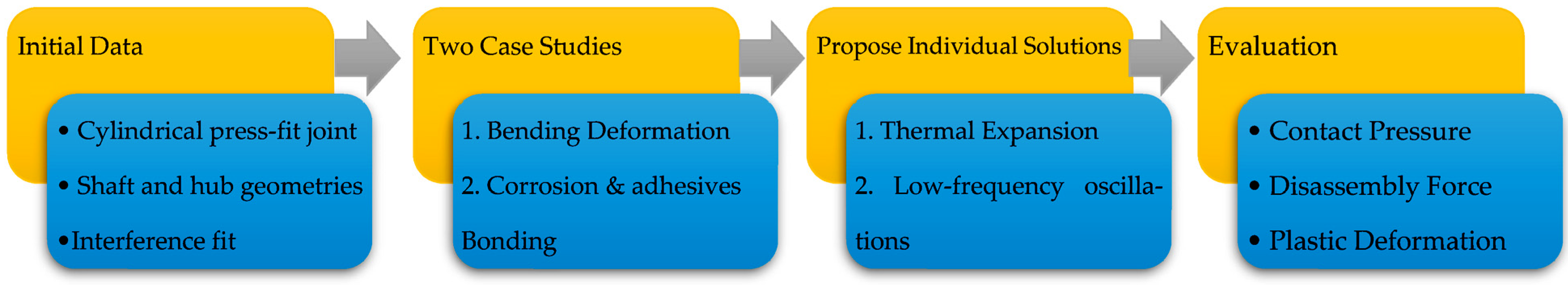
This study focused on investigating two common problems that arise during the disassembly process: deformation and corrosion of the mating components. To address these issues, thermal expansion and vibration-assisted disassembly techniques were examined. The research team developed a baseline model of an interference fit and validated it using literature data. The model accounted for normal wear of the joint and considered two scenarios: deformation caused by bending of the connected parts and an increase in COF due to corrosion. The study explored various approaches to reduce the pull-out force, minimize plastic strain in the parts, and prevent damage during and after disassembly.
Figure 1 provides a block diagram of the modelling sequence used in this study.
This study used a finite element model developed by Madej et al. [
25], which simulated the press-fit process of a simple pin-tube mechanical joint with different tolerances between the mating shaft and hole. Madej et al. analyzed both pressing and withdrawal modes and validated the model using experimental data from the same study and by comparing the assembly force graphs with those from another study conducted by Croccolo et al. [
26]. Based on the similar trends observed in the results, this model was selected as the baseline model for the current study.
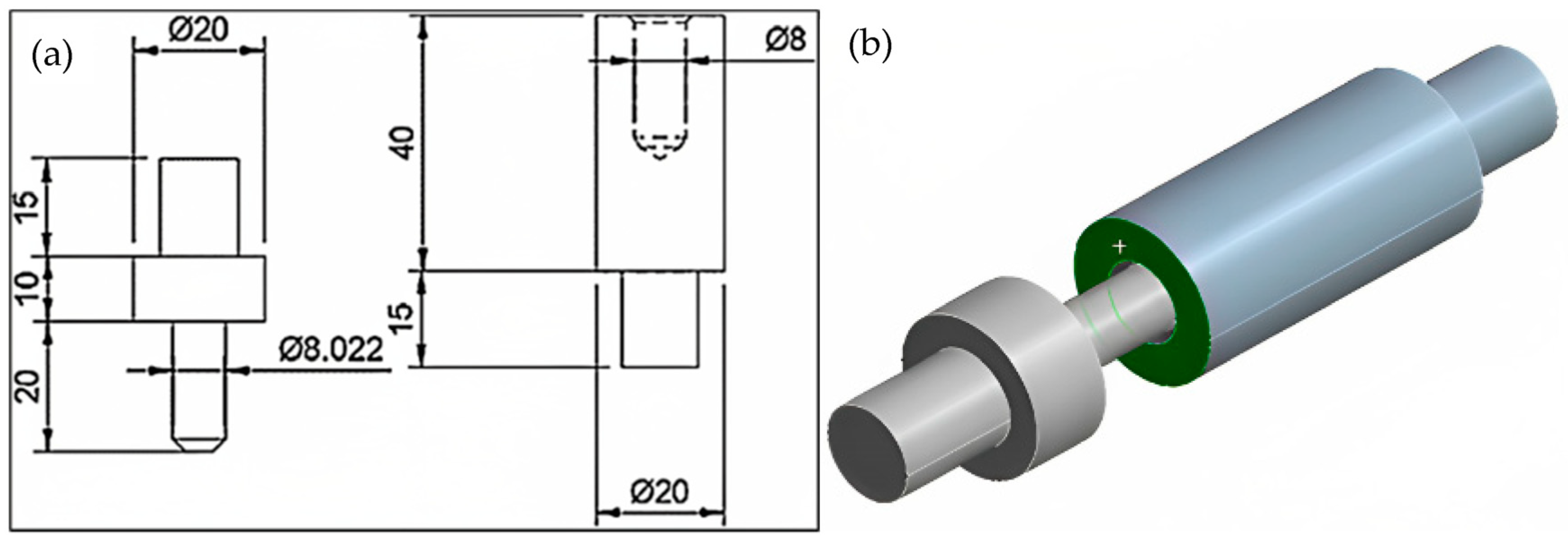
The finite element model for the press-fit joint was created using Ansys 2021, with the dimensions and shape of the shaft/hub fit shown in
Figure 2a. This fit corresponds to the J10 (O = 0.022 mm) specification as per the reference literature [
27]. The joint in this study follows the H7/s6 standard, which is a medium drive fit used for permanent assembly, commonly found in drive gears and sleeve bearings. Due to the difficulty in disassembling this type of joint without causing damage, it was selected for the current study. The material chosen for this study was S235 structural steel, which is a low-carbon manganese steel. S235 steel was selected for its common use in manufacturing, particularly in the automotive industry where remanufacturing is important. It has good weldability and machinability and is relatively inexpensive, making it a cost-effective choice for remanufacturing processes. Using this material allowed for a realistic and relevant analysis of the challenges associated with disassembling parts for remanufacturing.
To model the pressing assembly process, finite element analysis (FEA) was utilized as depicted in
Figure 3, replicating the model developed by Madej et al. [
25]. The shaft was displaced by 15 mm in the
Z-axis direction, with a step size of 0.5 mm. The material properties and plasticity data of the S235 steel alloy presented in
Table 1 and
Table 2 were applied to the mating parts (shaft and hub) in the model. The contact surface was modelled using the augmented Lagrange function with a COF of µ = 0.1. A support was fixed at the front outer surface of the hub, as shown in green (see
Figure 2b), following the method described in the literature [
25]. The maximum force over time was considered as the force required to assemble the joint, whereas the force required to displace the shaft from the hub by 0.1 mm was taken as the breaking force value. The baseline model was validated by comparing the obtained results with those from the literature, as described below. Subsequently, it was used to further analyze the interference fit disassembly.
Section 2.1 considered a bending couple to study deformed interference fits, while
Section 2.2 investigated corrosion, which is classified as the most significant problem in ND.
2.1. Thermal Expansion-Assisted Disassembly
Interference fits can lead to bending and torsion of the mating components, which increases their susceptibility to fretting and fatigue [
13]. Peaking stress occurs when the shaft and hub are subjected to bending loads, resulting in relative motion between them. Torsion only increases shear motion but may cause plastic deformation under high-stress conditions when slipping is prevented. According to Radi et al. [
8], the mating parts experience increasing pressure at the concave side and vice versa. The detachment bending couple is the moment needed to detach a hub from a shaft due to frictional forces at the interface. A mathematical model has been derived to calculate the detachment couple
C of a shaft-hub interface fit as shown in Equation (1), where
E is the Young’s modulus,
I is the diametrical interference,
I1 is the moment of inertia, and a is the shaft radius. The detachment couple is then applied to the shaft, as shown in
Figure 3, while the other end of the hub is fixed. The primary objective of this study is to prevent the increase in plastic deformation at the shaft/hub interface during disassembly, which is crucial for ND.
To facilitate disassembly through thermal expansion and reduce contact stress, an even heating process was applied to the hub. This approach is similar to shrink fitting, where a transient heat is applied to the hub during assembly, causing it to shrink while cooling after assembly [
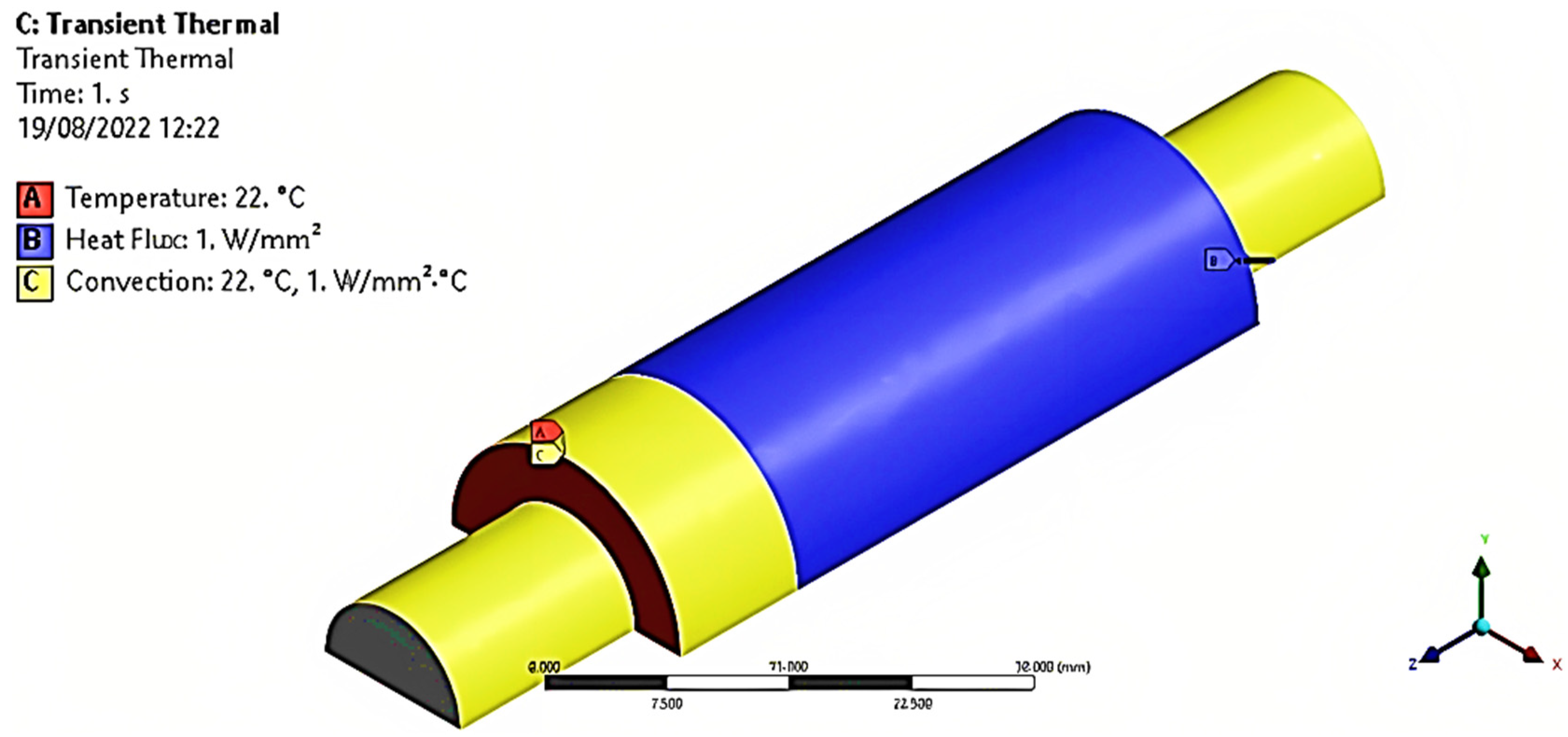
28]. Since the hub has a significantly larger surface area than the pin, the expansion of the hub would have a greater effect. To simulate actual heat transfer during disassembly, a transient thermal analysis was performed using Ansys Workbench 2021, as illustrated in
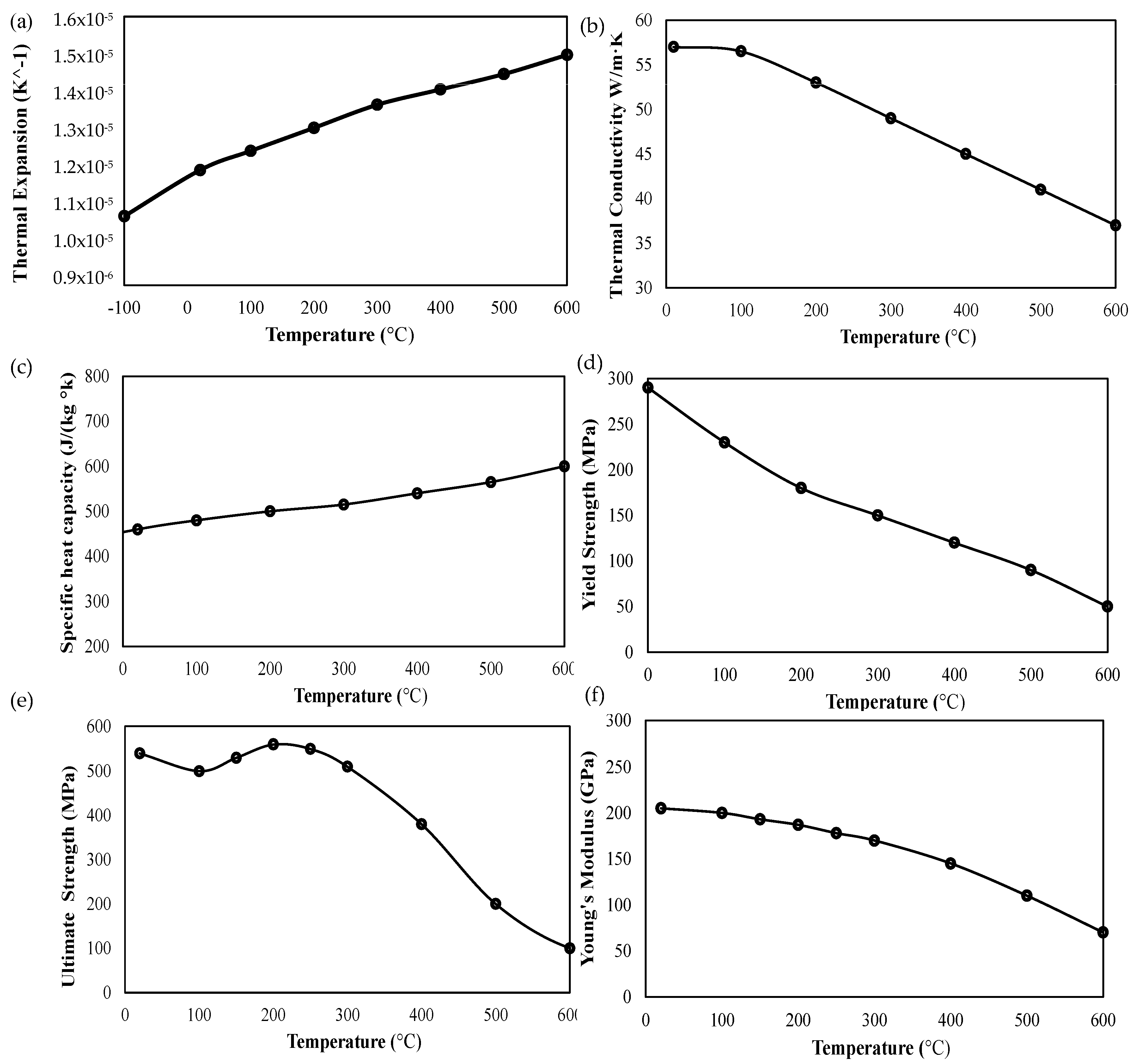
Figure 4. A heat flux was applied to the exterior of the hub, and both ends were assumed to be at room temperature, with convection taken into account. The initial temperature was maintained at 22 °C, and a displacement of 4.5 mm was applied to the shaft. The Ansys model implemented the mechanical and thermal properties of S235 steel at different temperatures, obtained from the literature [
29], and these are presented in
Figure 4. The study investigated the effect of thermal heating within a temperature range of less than 300 °C, as both the yield strength and Young’s modulus of the alloy decreased with increasing temperature. The elasticity was determined by Young’s modulus (E) and the tangent modulus, with the model keeping the latter constant. Young’s modulus is a measure of a material’s stiffness under axial tension or compression and is calculated as the ratio of stress to strain within the proportional limit. It is a constant value for a given material and is independent of the magnitude of the stress applied. By contrast, the tangent modulus is a measure of the local stiffness of a material at a specific point on its stress–strain curve and is calculated as the slope of the curve at that point. Unlike Young’s modulus, the tangent modulus is not a constant value but varies depending on the level of stress applied. It is worth noting from
Figure 4 that the thermal conductivity decreased by more than 13% after 300 °C, leading to less efficient heat transfer. Additionally, the tensile strength also experienced a drastic decline after 300 °C. Therefore, a heat flux in the range of 0.5 to 2 W/mm
2 was applied to avoid violating this constraint and keeping the part’s temperature below 300 °C, as shown in
Figure 4. The study determined the plastic strain, contact pressure, and disassembly force resulting from the transient thermal analysis.
2.2. Vibration-Assisted Disassembly
The S235 alloy, being a mild steel, is vulnerable to uniform corrosion when exposed to humid air. Previous studies by Gassama et al. and Kocanda et al. have shown that the coefficient of friction (COF) increases significantly when wear occurs in seawater [
31,
32]. These studies assumed that no anti-corrosion coatings were applied to the contact surfaces of the joint. In line with these findings, a COF of 0.6 was used in the current study for ANSYS static structural analysis. The selection of the coefficient of friction (COF) value of 0.6 was carefully considered and based on a thorough literature review and common industrial practices for similar applications. This value falls within the typical range for metal-on-metal contacts, such as those found in automotive components, and has been widely used in simulations and experiments related to remanufacturing processes. The wear effect was considered a combination of mechanical, abrasive, and corrosive factors, while the effects of time-dependent corrosion and loss of material were neglected. Previous studies by Dieudonné et al. and Gutowski et al. investigated the impact of longitudinal vibrations on friction forces in sliding motions [
15,
21]. Both studies applied oscillations of different frequencies to the support to simulate the acceleration force exerted on the hub in the same axis of sliding motion (i.e., the
z-axis in this FEM). In this study, vibration waves were applied as sinusoidal forces described by two functions presented in Equations (2) and (3). The force F varied with time t, and two different vibration amplitudes (1000 N and 5000 N) were considered while the frequency remained constant.
To examine the impact of higher frequencies on the disassembly process, a threshold of 1500 Hz was selected as a relatively high frequency [
33]. This was performed to bridge the gap between previous research conducted by Gutowski et al. [
21], who studied high frequency (4000 Hz), and Dieudonne’ et al. [
3], who examined low frequency (4–60 Hz). To further explore the impact of lower frequency, a frequency of 700 Hz was also included. During the disassembly process, vibration waves were applied simultaneously, while an extraction of 2 mm with a step of 0.2 mm was carried out. The breaking force was determined as the total force required to move 0.1 mm of the shaft. All other settings remained consistent with the baseline model described earlier.
3. Results and Discussion
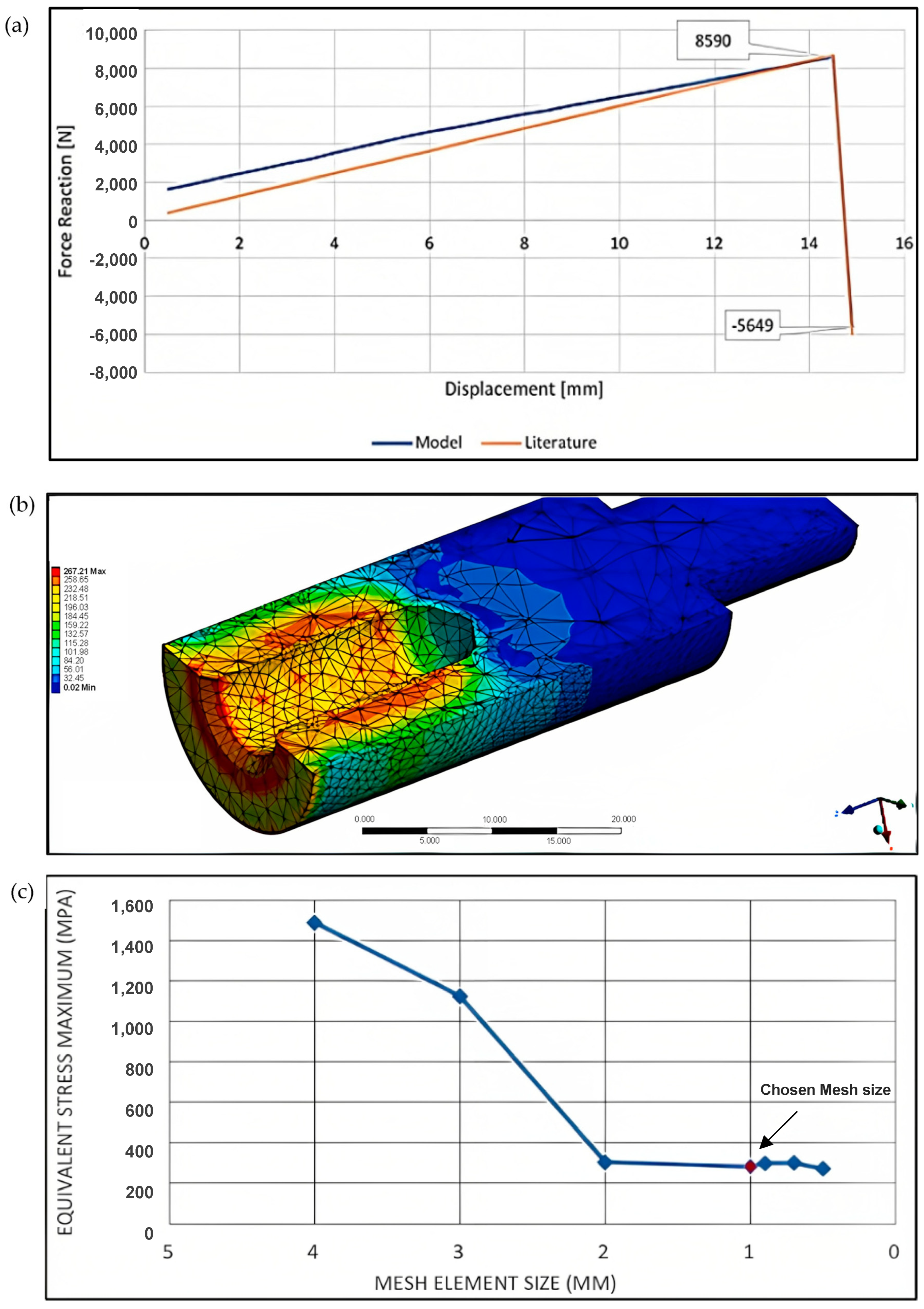
In this section, the results of the study on the disassembly force using developed FEA model are presented. The accuracy of the model is evaluated by comparing its results to those reported in the literature. The disassembly force predicted by the model and those reported in the literature [
26] are compared in
Figure 5a. The model estimates the breaking and assembly forces to be 8986 N and 6002 N, respectively, which is slightly higher than the literature-reported values of 8590 N and 5469 N. The model’s ability to accurately predict the disassembly force under different conditions indicates its usefulness in optimizing the design of bolted joints for specific applications. Additionally, the model predicts a maximum surface pressure of 267 MPa, as shown in
Figure 5b, which is slightly lower than the literature-reported value of 277 MPa. The difference may be due to the assumptions made in the model, such as the assumption of a perfectly flat contact surface between the bolt and the nut, which may not hold in real-world scenarios. However, the margin of error of approximately 5% indicates an acceptable level of accuracy in predicting the disassembly force under different conditions in the current study.
Figure 5b also shows that the inlet experiences a significant stress concentration, consistent with the findings of Pedersen [
13]. This stress concentration may be attributed to the geometric features of the inlet, such as its sharp edges and corners, which can act as stress concentrators. The identification of these stress concentrations can aid in the optimization of the bolted joint design to prevent failure. As discussed, the predicted assembly force was initially higher than that in the literature [
25]. This discrepancy may be due to the relatively larger overlapping areas of the shaft and hub in the current study. The model assumed an overlapping of 0.1 mm to set up the contact area roughness, which may have resulted in a higher predicted assembly force. However, this difference is not significant for the current study, as the primary objective was to reduce the breaking forces of the joint.
To further validate the results of the FEA model, a convergence analysis of the maximum equivalent stress was conducted, as shown in
Figure 5c. A mesh element size of 1 mm was selected, as the difference in the results was within 5%. This mesh element size was applied to the two cases considered in this study.
3.1. Thermal-Assisted Disassembly
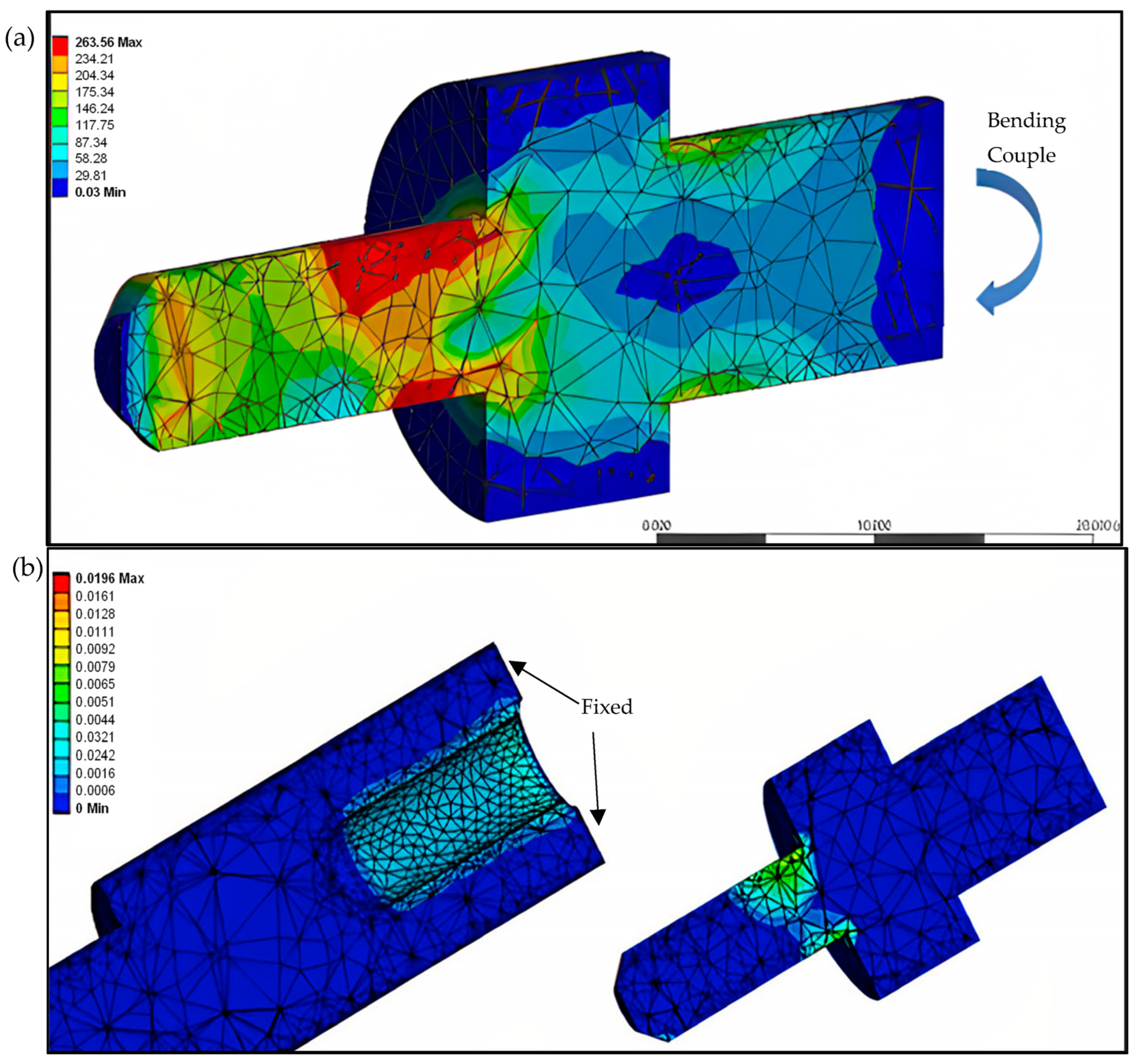
The results of the study on the decoupling process of a shaft-hub joint using numerical simulation are presented in this section. Equation (1) was used to determine the decouple moment, which was found to be approximately 25 kN mm. This value was then applied to the shaft, as shown in
Figure 6a. It is worth noting that the model used in this study had a protruding shaft. Therefore, the shaft-hub contact force was not directly loaded, and the shaft was only deformed compared to non-protruded ones [
8].
Figure 6b shows that plastic strain had developed around the edges of both the shaft and the hub. The goal of the numerical decoupling (ND) process was to avoid increasing such deformation and maintain the plastic strain as before disassembly.
Figure 6b illustrates that the plastic strain was confined to the edges of the shaft and hub, indicating that the elastic deformation was mainly responsible for transmitting the load. The model predicted that the maximum plastic strain was around 0.019, which is within the acceptable range for many engineering applications. The results of this study demonstrate that ND can effectively reduce the deformation and maintain the plastic strain of a shaft-hub joint during disassembly. This approach can potentially reduce the risk of joint failure and increase the lifespan of the joint. The model’s ability to accurately predict the plastic strain and deformation can help optimize the design of shaft-hub joints for specific applications.
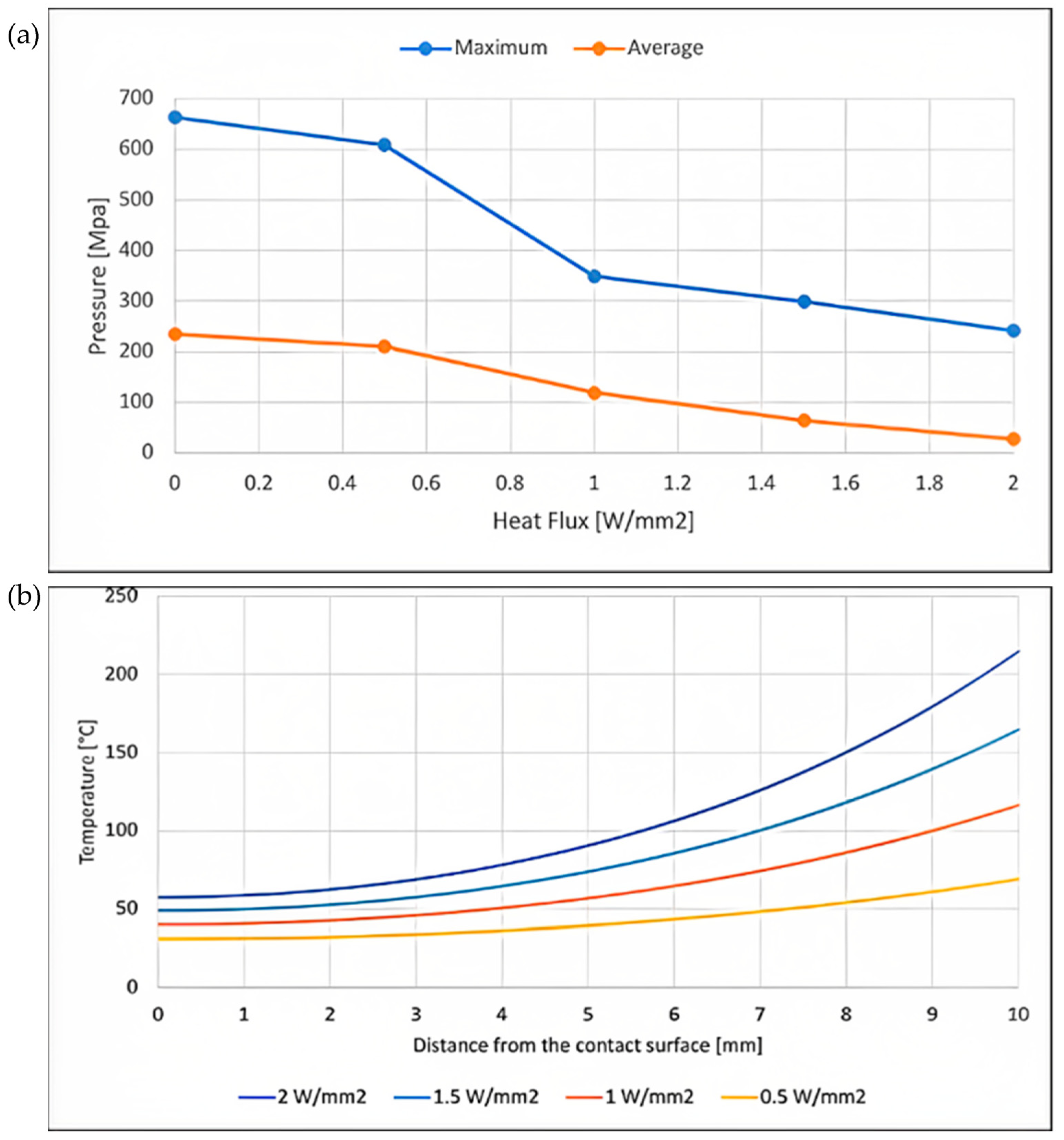
The change in contact pressure with increasing applied heat flux is analyzed using
Figure 7a. The maximum and average pressures are observed to decrease significantly as the heat flux is increased. Initially, with no heat applied, the maximum and average pressures are approximately 680 MPa and 230 MPa, respectively. However, at a heat flux of 2 W/mm
2, these values drop to approximately 250 MPa and 30 MPa, respectively. These results are consistent with those reported by Sen et al. [
29], who observed similar trends in both radial and hoop stress under the application of thermal energy. The reduction in contact pressure can be attributed to the thermal expansion of the hub and shaft, which reduces the compressive forces between the two components. Additionally, the local increase in temperature causes a decrease in the modulus of elasticity and an increase in the coefficient of thermal expansion, which further contributes to the reduction in contact pressure. It is important to note that the reduction in contact pressure can have significant implications for the structural integrity of the joint. In particular, it can increase the risk of fatigue failure and reduce the lifespan of the joint. Therefore, it is essential to carefully consider the effects of thermal loading when designing and analyzing mechanical joints.
The results showed that the applied heat flux had a significant effect on the temperature, contact pressure, and disassembly force of interference shaft-hub connections. As shown in
Figure 7b, the temperature along the external surface increased consistently with an increase in the stance from the contact surface, with the highest occurring at a heat input of (1 W/mm
2).
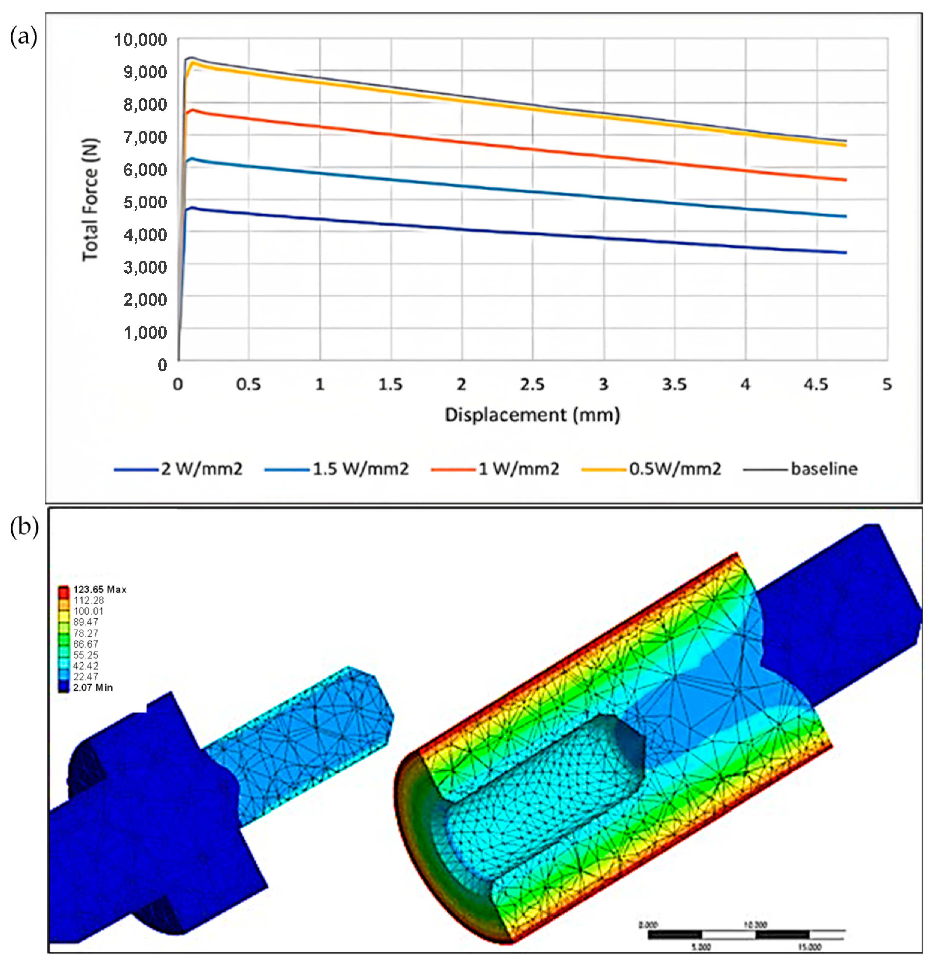
The temperature rise shown in
Figure 7b was found to be associated with a reduction in the disassembly force.
Figure 8a shows the lowest force required for disassembly was shown the least for the highest heat input (1 W/mm
2).
Figure 8b illustrates the temperature gradient through the joint at an applied heat flux of 2 W/mm
2. Notably, the effect of the applied heat flux is reduced at the interface between the shaft and hub, compared to the external heating surface. This is because the
Z-axis contact line, which is the most important zone affecting heat transfer in an interference shaft-hub connection, experiences a reduction in contact pressure due to the thermal expansion of the hub and shaft.
Comparing the results to the baseline model, the disassembly force was found to be reduced by approximately 18% and 50% at applied heat fluxes of 1 W/mm
2 and 2 W/mm
2, respectively. This reduction in the disassembly force can be explained by the decrease in contact pressure along the
Z-axis contact line, which is consistent with the findings of Sen et al. [
29]. These results have practical implications for the design and analysis of interference shaft-hub connections subjected to thermal loading, particularly in high-temperature applications. The reduction in the disassembly force observed in this study suggests that applying heat to the connection before disassembly could be an effective means of reducing the force required for disassembly. Additionally, the results highlight the importance of considering the effect of thermal loading on interference shaft-hub connections in the design and analysis process.
The values (both maximum and average) of plastic and thermal strains after disassembly, at different amounts of the heat flux applied, are given in
Table 3. The application of heat flux resulted in a reduction of approximately 7% and 3% in average plastic strain for heat fluxes of 0.5 and 1 W/mm
2, respectively, compared to direct disassembly (without heating). However, the maximum plastic strain remained constant with an increasing heat flux up to 1 W/mm
2 and then experienced a significant surge of about 140% when the heat flux was increased to 2 W/mm
2. This increase in the maximum plastic strain can be attributed to the induced thermal strain. The observed thermal strain increased by approximately 2500% as the heat flux was increased from 0.5 to 2 W/mm
2, as shown in
Table 3. These results are consistent with previous experimental findings by Sun et al. [
17], who reported a substantial rise in thermal plastic strains with increasing temperature above 200 °C for alloy S235. The study also found that temperature effects may induce solid plasticity and mechanical loads [
34]. As the ultimate tensile strength and the Young’s modulus of the alloy decreased after reaching 200 °C, as shown in
Figure 4, strains developed at lower stress values, which could explain the increase in the overall average plastic deformation to reach 1.73 × 10
−4. It should be noted that the current work did not study the cooling after thermal disassembly and the thermal strain-hardening effect. Further experimental studies would be required to allow more accurate determination of the actual plastic deformations and disassembly forces considering such influencers.
3.2. Vibration-Assisted Disassembly
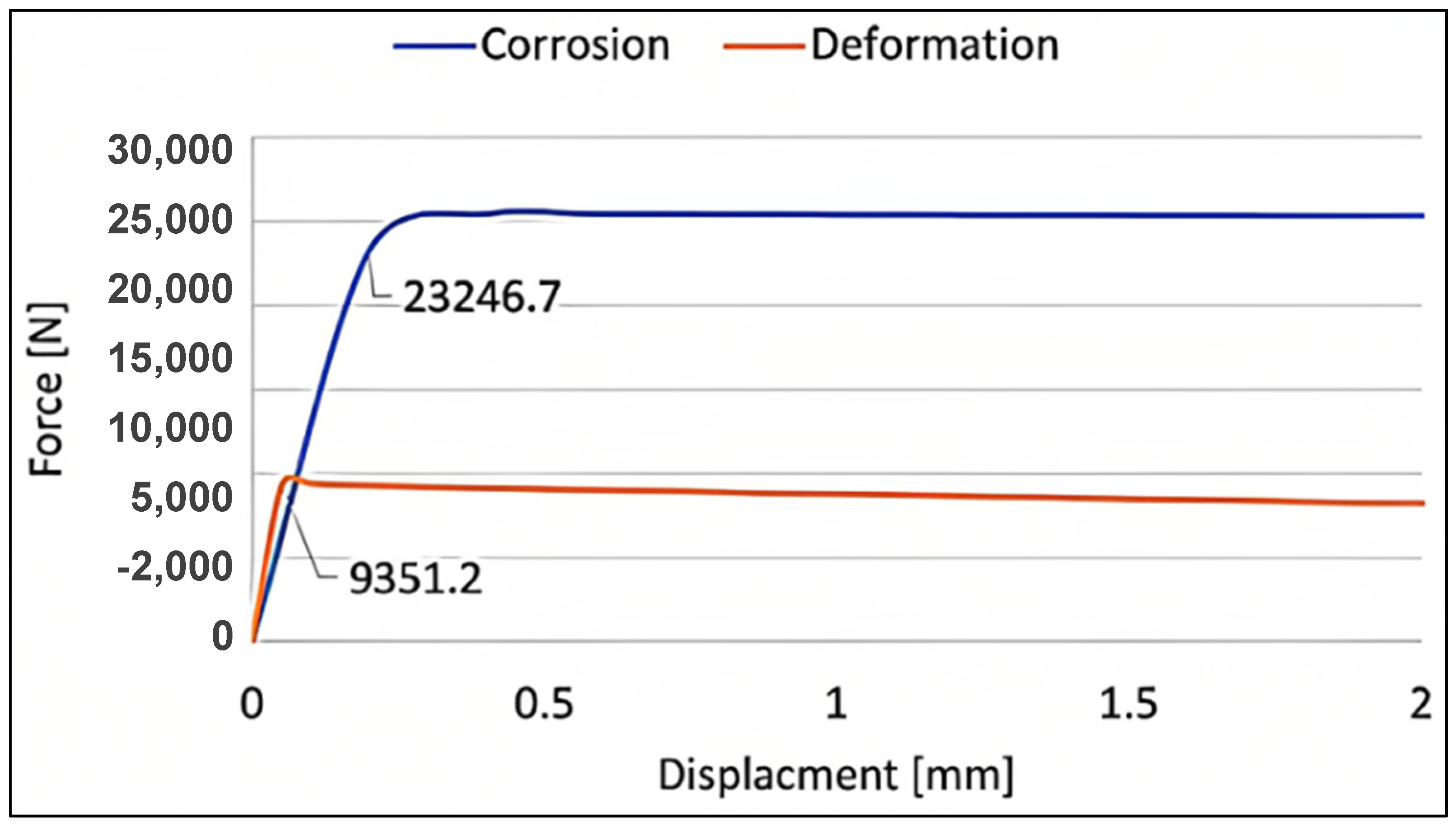
Figure 9 displays the baseline disassembly force versus displacement for both the deformation and corrosion cases. The vibration waves were applied as sinusoidal forces using Equations (2) and (3) as described earlier. From the figure, it is evident that increasing the coefficient of friction (COF) to 0.6 resulted in a significant increase in the required breaking force. Specifically, the breaking force increased by a factor of about 2.5, which indicates an increase in the difficulty of disassembly. The use of vibration waves for disassembling interference-fit assemblies can be further considered for future studies. In particular, the contact response with cyclic micro-slips and frictional dissipation in the joint to fully understand its feasibility and safety. The force amplitudes presented only refer to excitation. Finite element analysis with a contact algorithm can simulate the interaction between the shaft and hub, including friction and micro-slips, to determine the potential for joint damage or failure during disassembly.
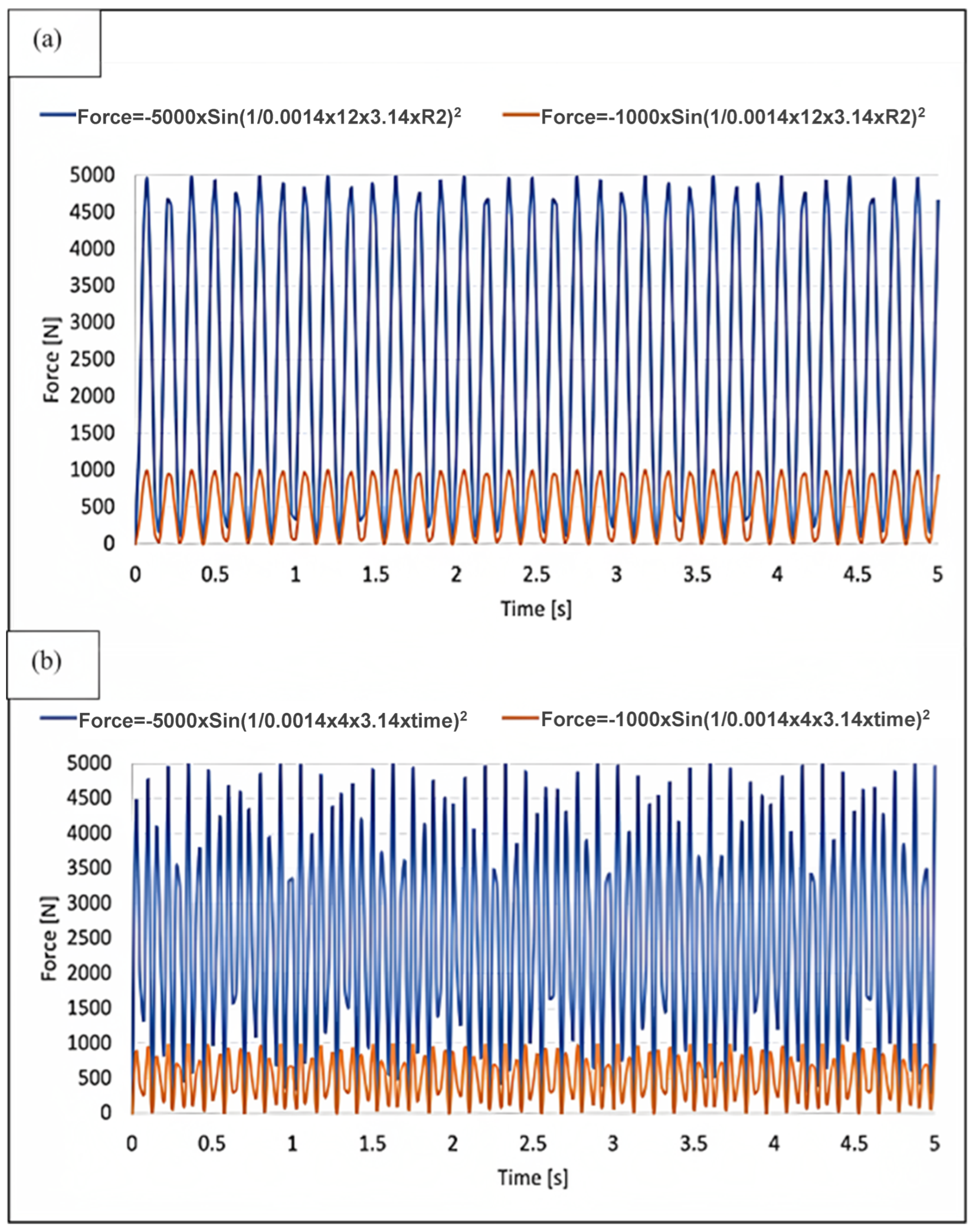
In this study, the motion graphs of different force amplitudes at frequencies of 700 and 1500 Hz were analyzed and presented in
Figure 10a,b, respectively. The harmonic response analysis was performed using Ansys to determine the natural frequency of the joint. It was found that the natural frequency of the joint was significantly higher than that of the applied vibrations. Therefore, the joint was not expected to achieve resonance, which could cause irreversible damage. This indicates the feasibility and safety of the proposed method for the disassembly of interference-fit assemblies through vibration waves.
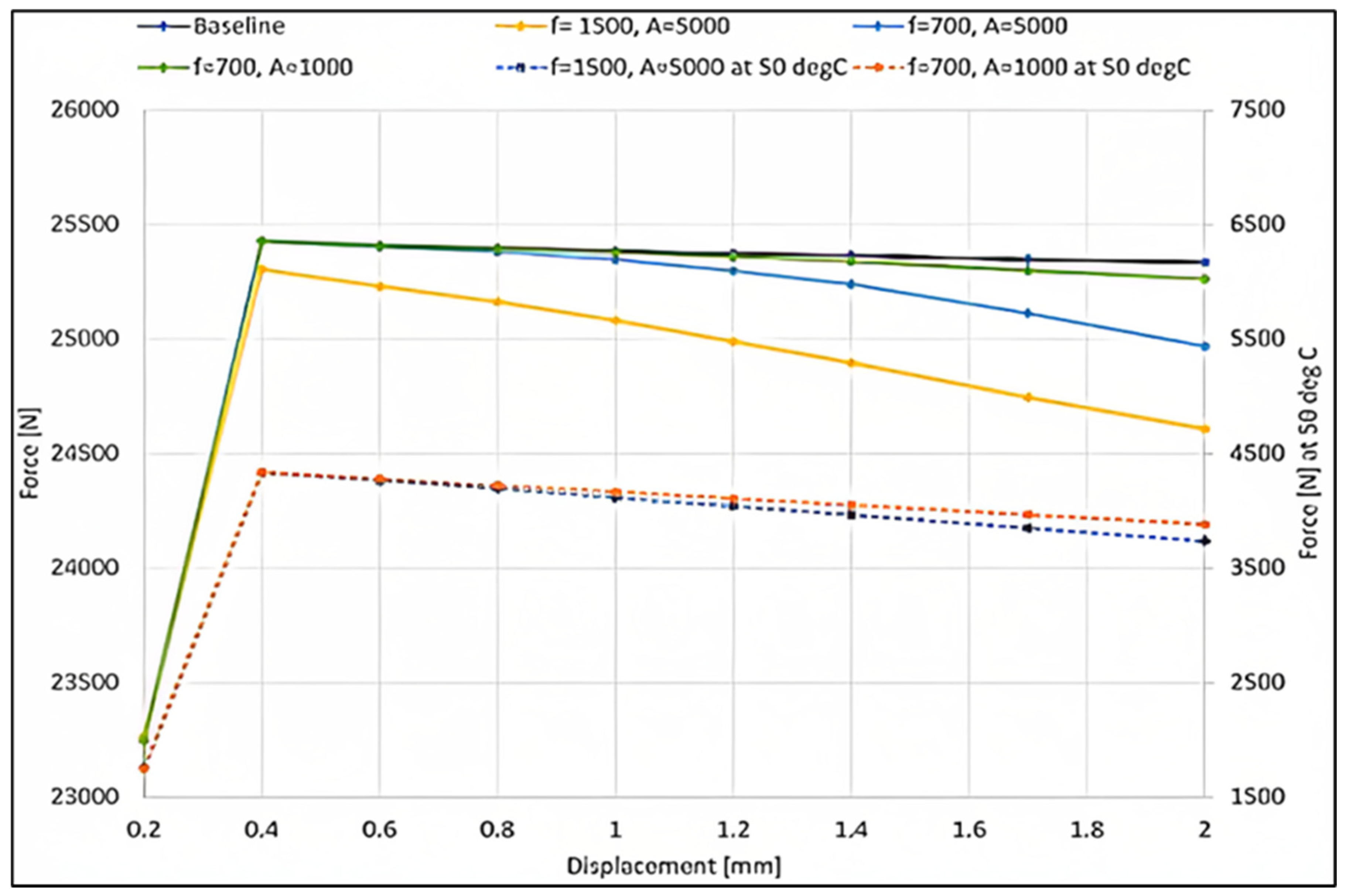
Figure 11 presents the effect of oscillation waves with various amplitudes and frequencies, as well as an increase in joint temperature, on the disassembly force. The results related to the thermal effect are plotted with respect to a secondary axis to the right. The baseline model required a disassembly force of approximately 25.4 kN. The application of a vibration wave with an amplitude of 1000 N and a frequency of 700 Hz did not have a significant effect. However, when either the amplitude or frequency was increased, the driving force was shown to decrease, particularly with increased displacement. For example, when a vibration wave with an amplitude of 5000 N and a frequency of 1500 Hz was applied, the breaking force at a displacement of 2 mm was about 24.6 kN. These findings are consistent with previous experimental studies that suggest that the driving force level can be controlled by changing the vibration amplitude or frequency [
3,
21]. Higher frequencies are thought to have a greater impact on elastoplastic deformation and surface roughness, resulting in a reduced friction force and thus a decrease in the required disassembly force.
It should be noted that the maximum achieved reduction in the disassembly force due to application of vibration was about 5%, which was significantly smaller than that reported in the literature, which was about 60% [
3]. This difference could be attributed to variations in geometry, interference, and vibration parameters. For example, the diameter of the cylindrical pin used in the current study was 8 mm, while in the literature, it was less than 1 mm. Additionally, the contact area between the shaft and the hub was much larger in the current study, which increased the force exerted due to friction and decreased the effect of the applied oscillation waves.
Further research could investigate the effect of higher frequency and an amplitude of oscillation waves, which would exert a higher impact of energy. Additionally, researchers could consider the thermal effect of oscillation waves, which could activate internal particles of the mating parts, enhance their relative motion, increase the temperature of the joint, and result in thermal softening, thereby decreasing the entire dynamic deformation resistance [
24]. With the reduction in contact stress, the reduction in the disassembly force would be more drastic.
Regarding plastic strain, the maximum plastic strain was decreased from 1.57 × 10
−2 to 1.83 × 10
−3, 1.72 × 10
−4, and 1.56 × 10
−4, respectively, when vibration waves of (frequency 700 Hz and amplitude 1000 N), (frequency 700 Hz and amplitude 5000 N), and (frequency 1500 Hz and amplitude 5000 N) were applied, which was equivalent to about an 88%, an 89%, and a 99% reduction in the maximum plastic strain. The average plastic stain also exhibited comparable lessening due to the application of the vibration waves. This softening effect of oscillation waves on plastic strain was previously suggested in the literature [
24]. Moreover, the study showed that increasing both the amplitude and/or the frequency of the vibrations applied had a positive effect on the softening effect, which was confirmed by the current results.
Table 4 shows the plastic and thermal strains after disassembly at different amplitudes and frequencies of the oscillation waves applied. The table shows that applying vibration only does not reduce the plastic strain. The current study noted that the strain hardening effect was not taken into account in the model, which could lead to an overestimation of the reduction in the plastic strain after applying the vibration waves. Additionally, the plastic deformation at the micro-surfaces requires further investigation. Nevertheless, the results indicated that ND could still be implemented effectively with the aid of oscillation waves, even though the force reduction due to vibration was not significant. The effect of different vibration parameters needs to be investigated further.
Figure 11 and
Table 4 showed that applying a heat flux of 1 W/mm
2 simultaneously with the oscillation waves resulted in a higher reduction in both plastic strain and breaking up force. This was suggested to be due to the decreased contact pressure. For instance, when a 1 W/mm
2 heat flux was applied concurrently with an oscillation wave of an amplitude of 5000 N and a frequency of 1500 Hz, the average plastic deformation and disassembly force (at a 2 mm displacement) were reduced to 2.57 × 10
−7 and 3700 N, respectively. This reduction was equivalent to about 99% and 85%, respectively, compared to the case when the vibration wave of the same amplitude and frequency was applied alone (without thermal heating). These findings indicate that thermal disassembly could be more efficient than low-frequency oscillations with a suitable temperature increase.


 ,
, 


