
An Efficient Structural Optimization Method for the Hinge Beam of a Cubic Press

Abstract
:1. Introduction
2. Finite Element Simulation
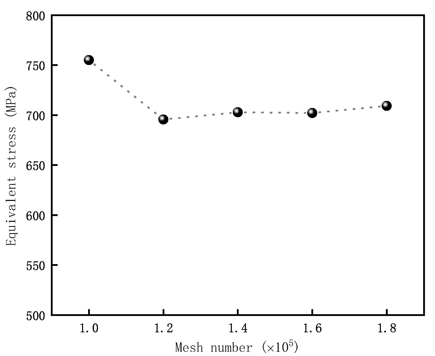
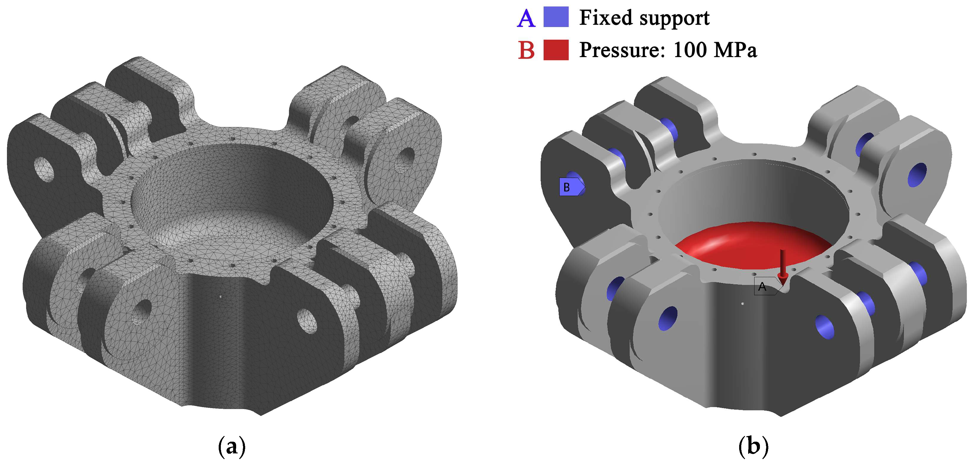
2.1. Finite Element Model Setup
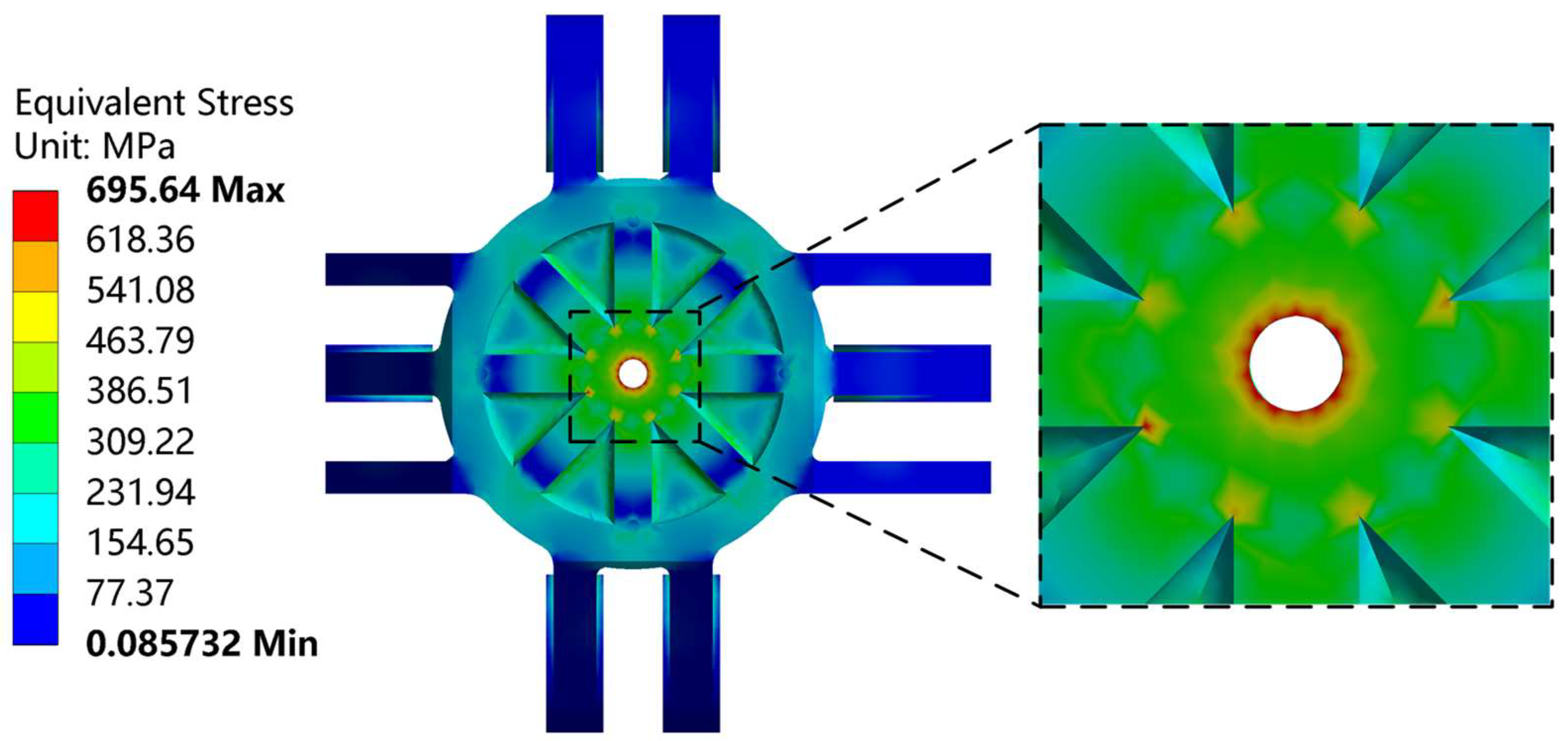
2.2. Finite Element Results
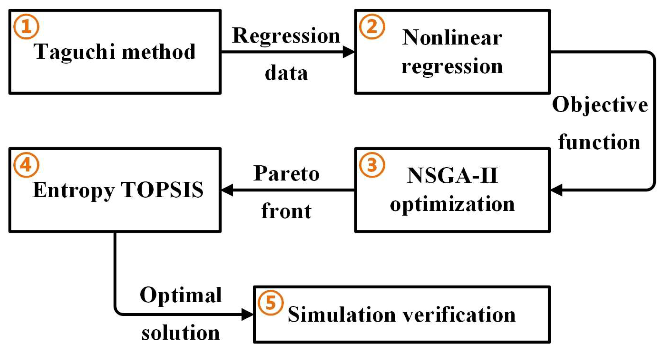
3. Taguchi Method
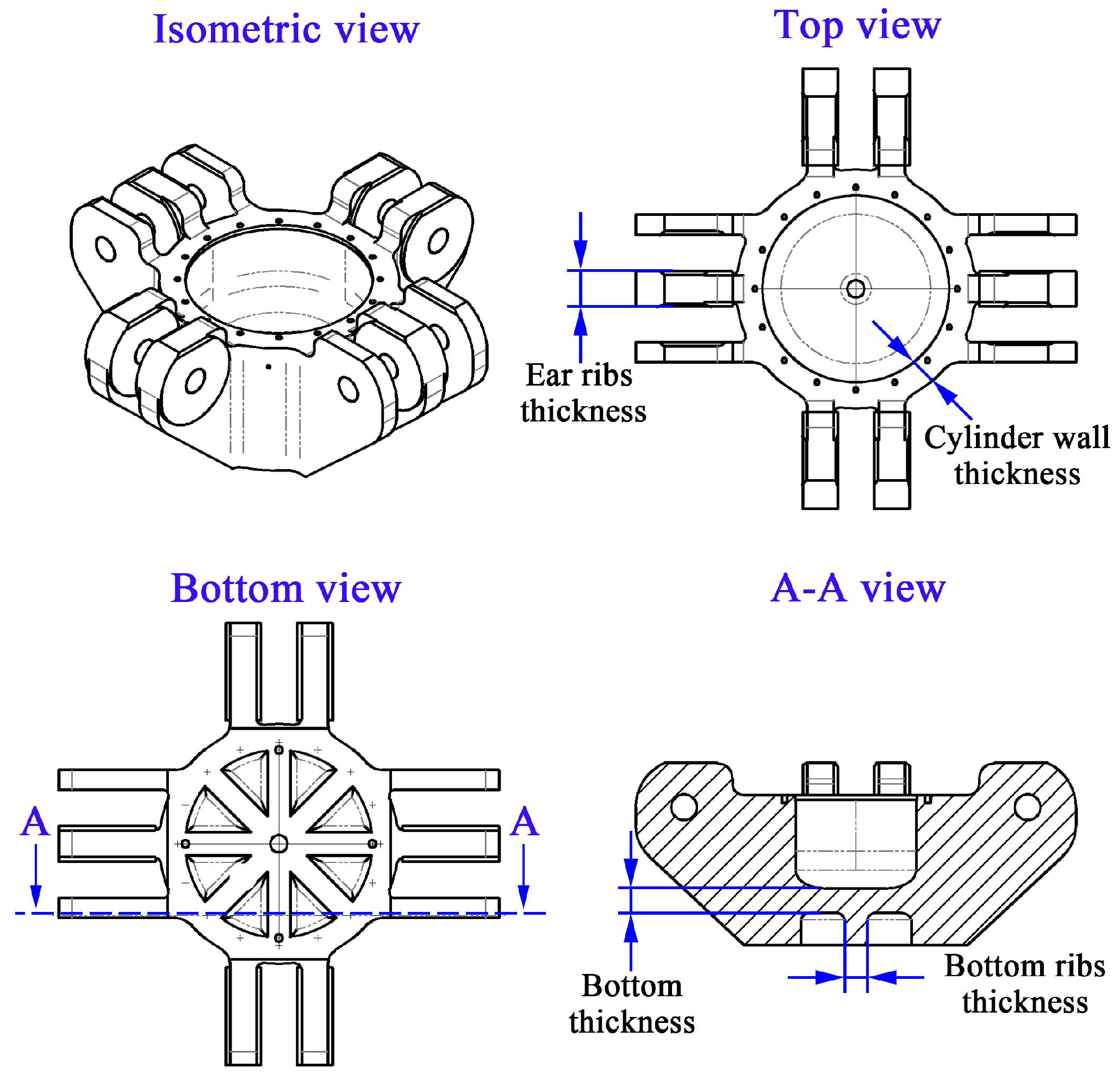
3.1. Influencing Factors
3.2. Taguchi Method Setup
3.3. Taguchi Method Results
4. Multi-Objective Optimization
4.1. Objective Function
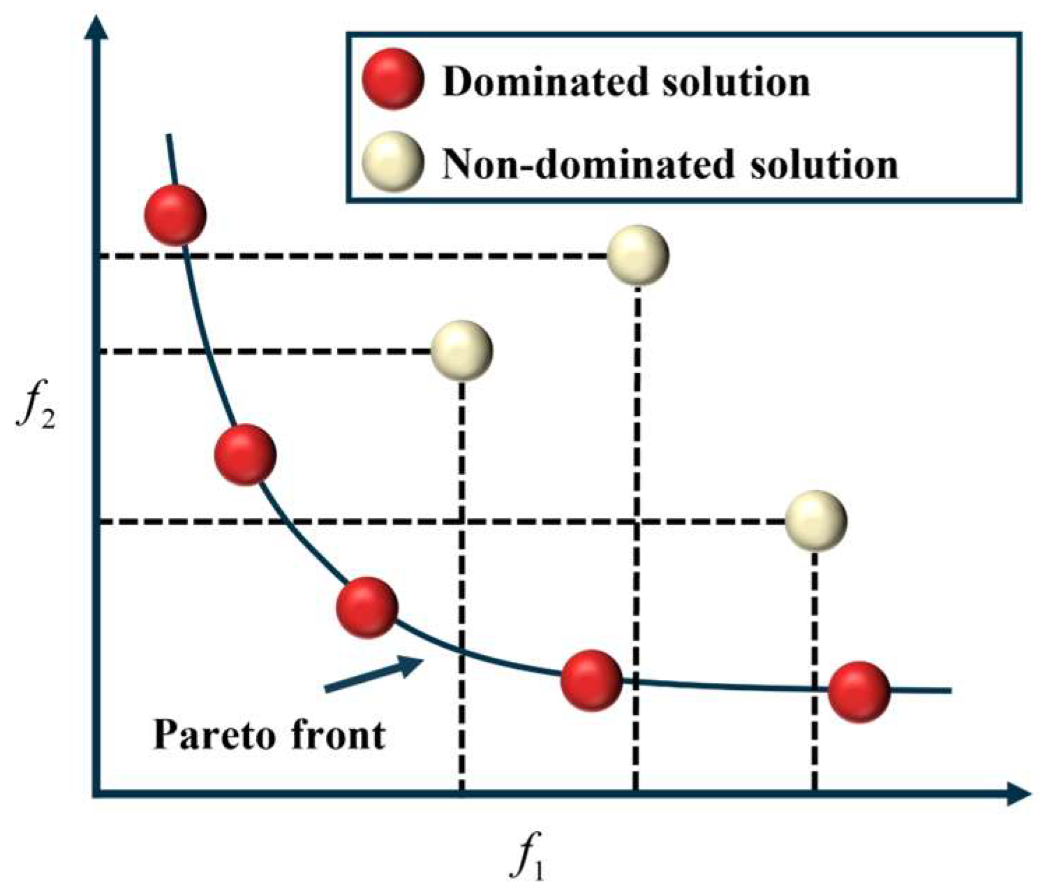
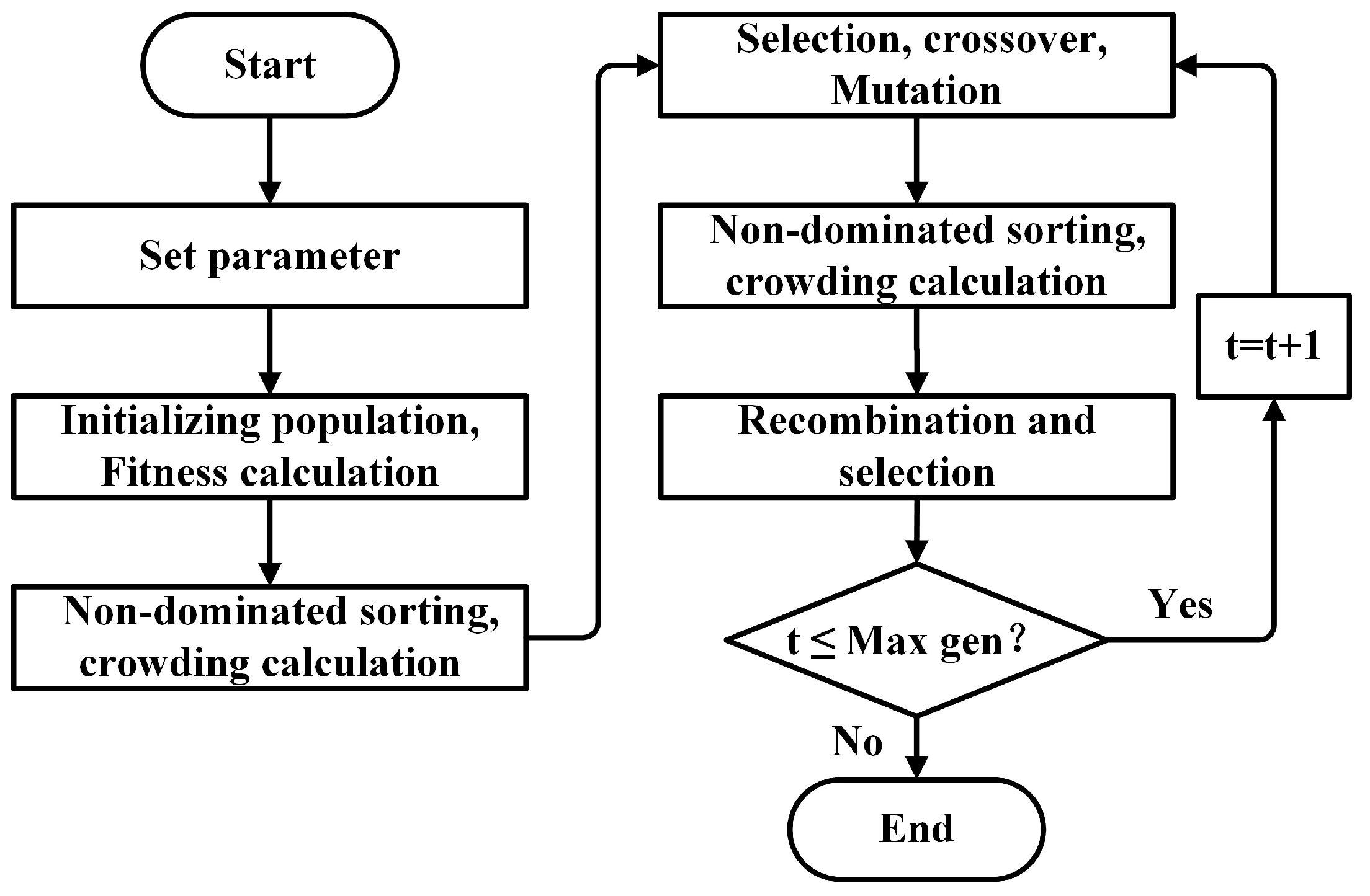
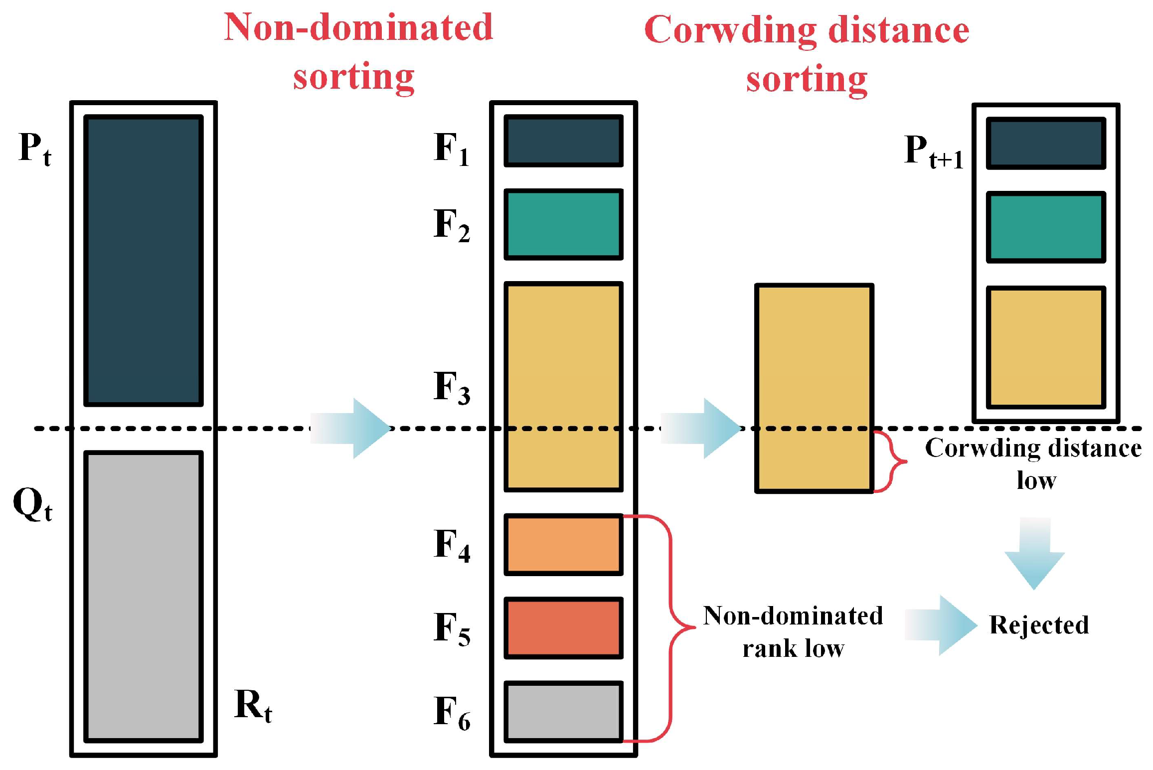
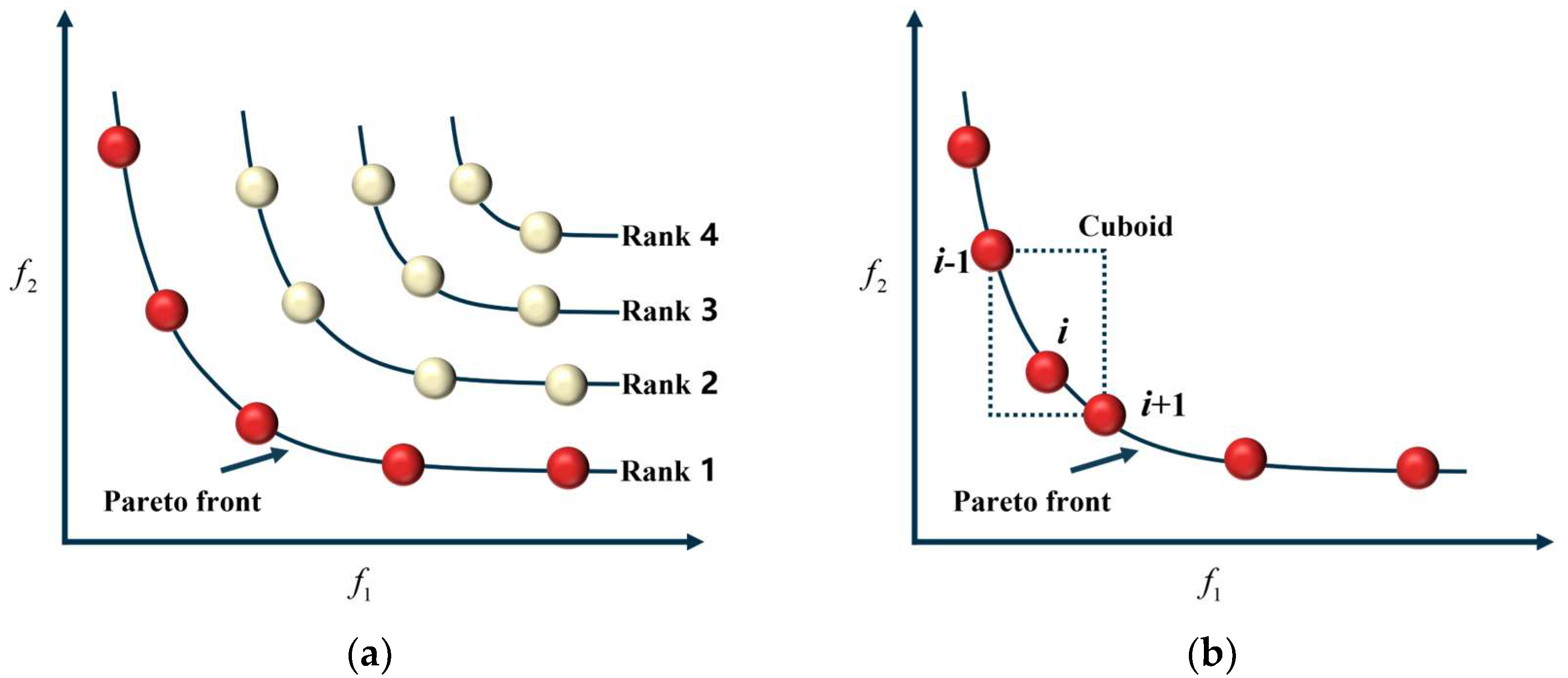
4.2. NSGA-II Algorithm
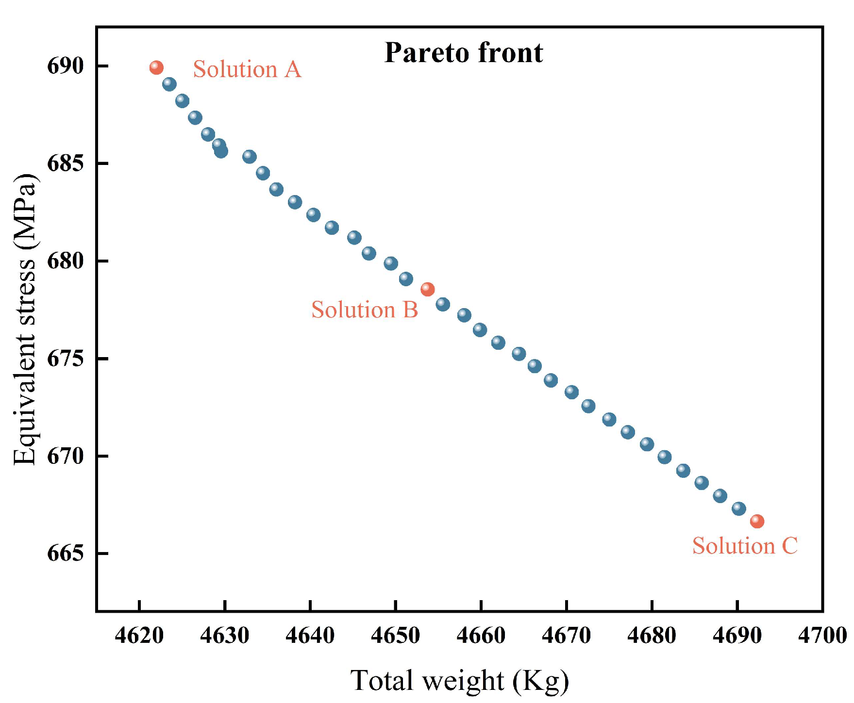
4.3. Optimization Results
4.4. Entropy-TOPSIS Method
- (1)
- Constructing and normalizing the decision matrix
- (2)
- Calculate the information entropy value, probability matrix, and entropy weight as follows:
- (3)
- Calculate the Euclidean distance of each evaluation index relative to the ideal and the negative ideal.
- (4)
- The relative closeness is determined as
4.5. Optimal Solution and Validation
5. Conclusions
- (1)
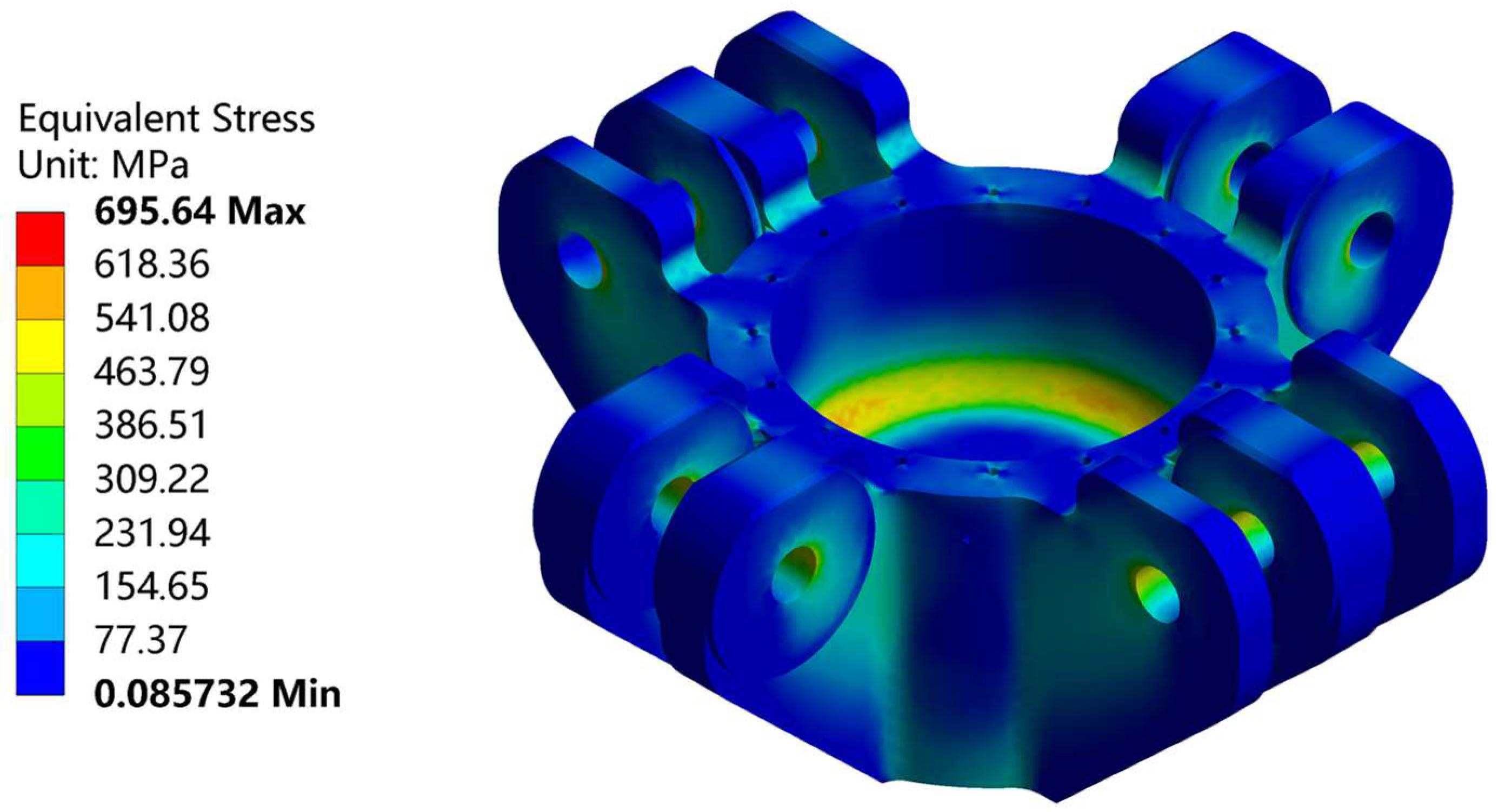
- The FEM results show that the stress distribution of the hinge beam is not uniform under the rated working condition, which has a serious stress concentration. The maximum equivalent stress of the hinge beam is located at the inlet hole edge with a value of 695.64 MPa.
- (2)
- The range analysis results show that the bottom ribs’ thickness has the greatest effect on the maximum stress, while the cylinder walls’ thickness has the greatest effect on the total weight. The large differences in factor significance order for maximum stress and total weight indicate safety and economy as conflicting optimization objectives.
- (3)
- Based on the entropy–TOPSIS method and the NSGA-II multi-objective optimization algorithm, the following optimal structural parameters of the hinge beam are obtained: bottom thickness 107 mm, ear ribs thickness 105 mm, bottom ribs thickness 120 mm, and cylinder wall thickness 105 mm. The total weight and maximum stress are reduced by 199.121 kg and 11.97 MPa, respectively, with a reduction of 4.12% and 1.72%.
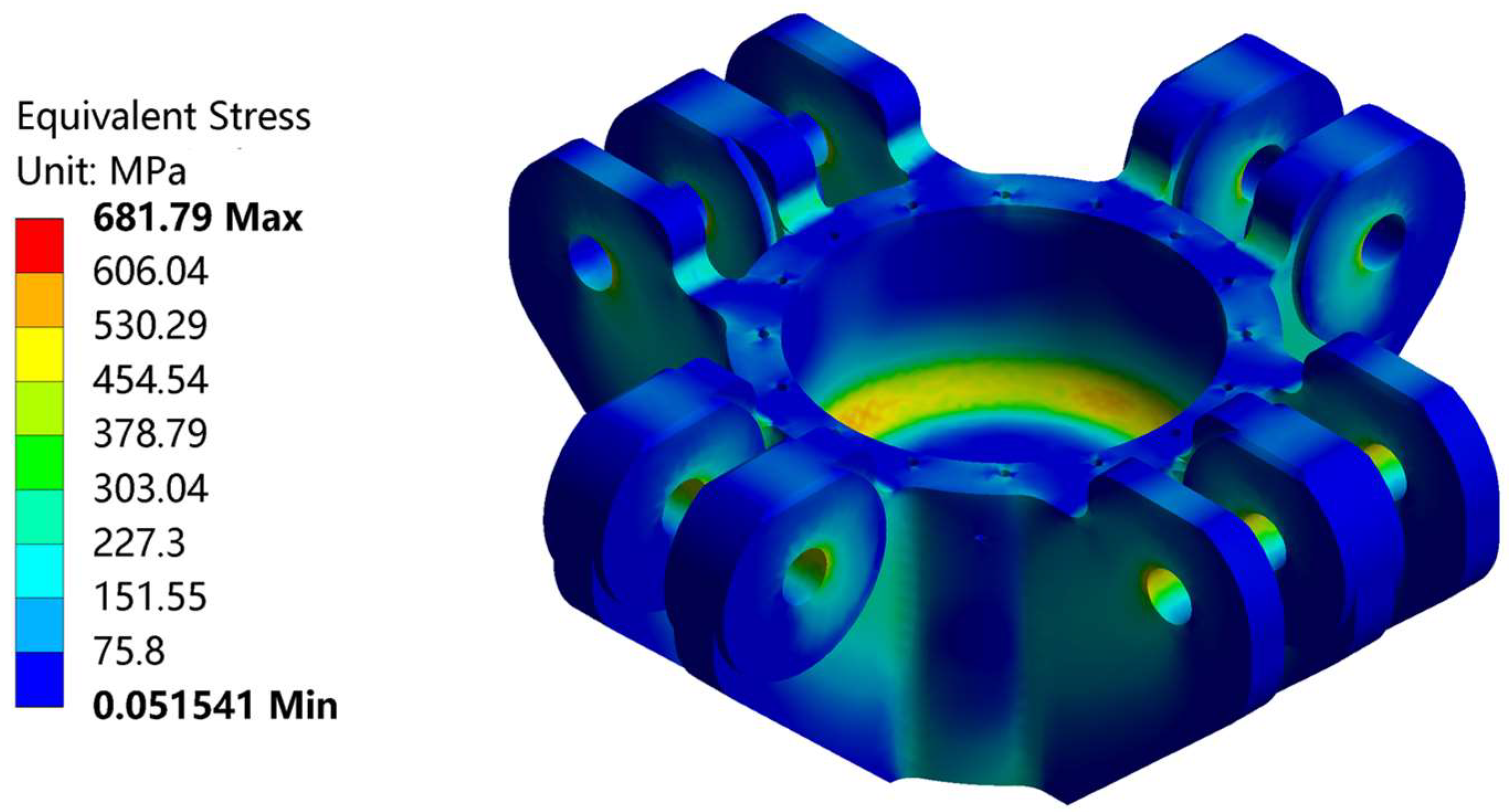
- (4)
- Numerical simulations of the hinge beam are carried out under the optimal structural parameters. The simulation results of the maximum stress and total weight are 681.79 MPa and 4625.874 kg, respectively, and the algorithm optimization results for the maximum stress and total weight are 683.67 MPa and 4636.054 kg, respectively. Upon comparing the algorithm optimization and simulation results, we found that the simulation error is 0.22% for total weight and 0.27% for maximum stress. This indicates that the hinge beam structure optimization method adopted in this paper is accurate and reliable, which effectively shortens the development cycle of the new hinge beam and reduces the cubic press total cost.
Author Contributions
Funding
Institutional Review Board Statement
Informed Consent Statement
Data Availability Statement
Conflicts of Interest
References
- Gan, J.; Gao, H.; Wen, S.; Zhou, Y.; Tan, S.; Duan, L. Simulation, forming process and mechanical property of Cu-Sn-Ti/diamond composites fabricated by selective laser melting. Int. J. Refract. Met. Hard Mater. 2020, 87, 105144. [Google Scholar] [CrossRef]
- Fu, S.; Yang, H.; Sun, S.; Zhang, M.; Liu, Y.; Zhang, Y.; Jiang, Z.; Pan, L. Investigation on the surface roughness modeling and analysis for ultra-precision diamond turning processes constrained by the complex multisource factors. Proceedings of the Institution of Mechanical Engineers. J. Eng. Manuf. Part B 2022, 236, 1295–1304. [Google Scholar] [CrossRef]
- Yang, Y.; Mimouni, M.; Trinh, T.; Sorkin, N.; Cohen, E.; Santaella, G.; Rootman, D.S.; Chan, C.C.; Slomovic, A.R. Phototherapeutic keratectomy versus epithelial debridement combined with anterior stromal puncture or diamond burr for recurrent corneal erosions. Can. J. Ophthalmol. 2022. [Google Scholar] [CrossRef] [PubMed]
- Zhu, P.; Wang, P.; Shao, P.; Lin, X.; Xiu, Z.; Zhang, Q.; Kobayashi, E.; Wu, G. Research progress in interface modification and thermal conduction behavior of diamond/metal composites. Int. J. Miner. Metall. Mater. 2022, 29, 200–211. [Google Scholar] [CrossRef]
- Liu, F.; Zhang, D.Z.; Zhang, P.; Zhao, M.; Jafar, S. Mechanical Properties of Optimized Diamond Lattice Structure for Bone Scaffolds Fabricated via Selective Laser Melting. Materials 2018, 11, 374. [Google Scholar] [CrossRef]
- Jiang, X.; Deng, L. Multiphysics coupled plasma simulation of MPCVD diamond single crystal growth. In Proceedings of the International Conference on Computational Modeling, Simulation, and Data Analysis SPIE, Sanya, China, 3–5 December 2021. [Google Scholar]
- Vermeeren, V.; Wenmackers, S.; Wagner, P.; Michiels, L. DNA Sensors with Diamond as a Promising Alternative Transducer Material. Sensors 2009, 9, 5600–5636. [Google Scholar] [CrossRef]
- Diggle, P.L.; D’Haenens-Johansson, U.F.S.; Green, B.L.; Welbourn, C.M.; Tran Thi, T.N.; Katrusha, A.; Wang, W.; Newton, M.E. Decoration of growth sector boundaries with nitrogen vacancy centers in as-grown single crystal high-pressure high-temperature synthetic diamond. Phys. Rev. Mater. 2020, 4, 093402. [Google Scholar] [CrossRef]
- Yang, X.; Deng, F. Synthesis and characterisation of Φ62 mm polycrystalline diamond compact. Diamond Relat. Mater. 2019, 100, 107594. [Google Scholar] [CrossRef]
- Sun, X.; Qi, W.Z.; Zhao, H.; Li, H.X. Study on Fatigue of Hinge Sleeve of Cubic Press based on ANSYS. Appl. Mech. Mater. 2014, 457, 585–588. [Google Scholar] [CrossRef]
- Wu, W.-H.; Young, W.-B. Structural Analysis and Design of the Composite Wind Turbine Blade. Appl. Compos. Mater. 2012, 19, 247–257. [Google Scholar] [CrossRef]
- Guo, Z.; Li, H.; Gu, C. Finite element analysis and structural optimization of V-shaped seal ring based on ANSYS Workbench. J. Phys. Conf. Ser. 2022, 2383, 012106. [Google Scholar] [CrossRef]
- Liu, C.; Wei, X.; Yi, Z.; Li, Z.; Zhu, C.; Ma, Z. Strength Analysis and Structure Optimization of the Crankshaft of an Opposed-Power Reciprocating Pump. Machines 2023, 11, 123. [Google Scholar] [CrossRef]
- Ma, L.; Lu, B.; Yuan, Y.; Zhang, Y. The stress analysis and tests on the hinge beam of the diamond synthesis cubic press. In Proceedings of the 2016 3rd International Conference on Mechanics and Mechatronics Research (ICMMR 2016), Chongqing, China, 15–17 June 2016. [Google Scholar]
- Guan, A.; Zhou, S.; Gu, W.; Liu, Z.; Liu, H. A novel dynamic simulation approach for Gas-Heat-Electric coupled system. Appl. Energy 2022, 315, 118999. [Google Scholar] [CrossRef]
- Wang, Y.; Zhao, J.; Zhao, R. Shape Parameterization Optimization of Thermocouples Used in Aeroengines. Aerospace 2023, 10, 202. [Google Scholar] [CrossRef]
- Saka, M.P.; Hasançebi, O.; Geem, Z.W. Metaheuristics in structural optimization and discussions on harmony search algorithm. Swarm Evol. Comput. 2016, 28, 88–97. [Google Scholar] [CrossRef]
- Tan, W.; Chen, Z.; Li, Z.; Yan, H. Thermal-Fluid-Solid Coupling Simulation and Oil Groove Structure Optimization of Wet Friction Clutch for High-Speed Helicopter. Machines 2023, 11, 296. [Google Scholar] [CrossRef]
- Song, Z.; Li, J.; Han, X.; Xu, L.; Lu, L.; Ouyang, M.; Hofmann, H. Multi-objective optimization of a semi-active battery/supercapacitor energy storage system for electric vehicles. Appl. Energy 2014, 135, 212–224. [Google Scholar] [CrossRef]
- Hou, J.; Li, S.; Pan, W.; Yang, L. Co-Simulation Modeling and Multi-Objective Optimization of Dynamic Characteristics of Flow Balancing Valve. Machines 2023, 11, 337. [Google Scholar] [CrossRef]
- Li, C.; Liu, X.; Wang, X.; Chen, J.; Wang, Y. Optimization of Multi-Way Valve Structure in Digital Hydraulic System of Loader. Energies 2021, 14, 700. [Google Scholar] [CrossRef]
- Wang, Z.; Sun, X.; Chen, S. Multi-objective parameters optimization design of self-excited oscillation pulsed atomizing nozzle. J. Braz. Soc. Mech. Sci. Eng. 2019, 41, 510. [Google Scholar] [CrossRef]
- Sun, X.; Shi, J.X.; Zhong, Z.X.; Zhao, H. Study on architecture of measurement of multi-points strain of hinge sleeve of cubic press under super-high pressure. Appl. Mech. Mater. 2014, 596, 472–475. [Google Scholar] [CrossRef]
- Li, R.; Xu, B.; Zhang, Q.; Gu, X.; Zheng, G.; Ma, H.; Jia, X. Finite-element analysis on pressure transfer mechanism in large-volume cubic press. High Press. Res. 2016, 36, 575–584. [Google Scholar] [CrossRef]
- Song, G.; Ma, D.; Zhou, X.; Wang, L.; Wei, Z.; Xu, C.; Wang, W.; Wang, L.; Zhao, Y.; Wang, S. Operation of large-volume cubic press above 8 GPa and 2500 °C with a centimeter-sized cell volume using an optimized hybrid assembly. High Press. Res. 2021, 41, 132–141. [Google Scholar] [CrossRef]
- Wang, M.; Ma, Y.; Liu, F. A novel virtual cutting method for deformable objects using high-order elements combined with mesh optimisation. Int. J. Med. Robot. Comput. Assist. Surg. 2022, 18, e2423. [Google Scholar] [CrossRef] [PubMed]
- Revanasiddesh, B.V.; Taj, A.P.; Kumar, N.S.N.; Suresh, B.S. Extraction of modal parameters of CNC lathe bed using finite element and experimental method. Mater. Today Proc. 2020, 24, 398–405. [Google Scholar] [CrossRef]
- Danicic, D.; Sedmak, S.; Ignjatovic, D.; Mitrovic, S. Bucket Wheel Excavator Damage by Fatigue Fracture–Case Study. Procedia Mater. Sci. 2014, 3, 1723–1728. [Google Scholar] [CrossRef]
- du Plessis, A.; Broeckhoven, C.; Yadroitsava, I.; Yadroitsev, I.; Hands, C.H.; Kunju, R.; Bhate, D. Beautiful and Functional: A Review of Biomimetic Design in Additive Manufacturing. Addit. Manuf. 2019, 27, 408–427. [Google Scholar] [CrossRef]
- Mojaver, P.; Khalilarya, S.; Chitsaz, A.; Assadi, M. Multi-objective optimization of a power generation system based SOFC using Taguchi/AHP/TOPSIS triple method. Sustain. Energy Technol. Assess. 2020, 38, 100674. [Google Scholar] [CrossRef]
- Kitayama, S.; Yamazaki, K. Compromise point incorporating trade-off ratio in multi-objective optimization. Appl. Soft Comput. 2012, 12, 1959–1964. [Google Scholar] [CrossRef]
- Srinivas, N.; Deb, K. Muiltiobjective Optimization Using Nondominated Sorting in Genetic Algorithms. Evol. Comput. 1994, 2, 221–248. [Google Scholar] [CrossRef]
- Deb, K.; Pratap, A.; Agarwal, S.; Meyarivan, T. A fast and elitist multiobjective genetic algorithm: NSGA-II. IEEE Trans. Evol. Comput. 2002, 6, 182–197. [Google Scholar] [CrossRef]
- Méndez, M.; Frutos, M.; Miguel, F.; Aguasca-Colomo, R. TOPSIS Decision on Approximate Pareto Fronts by Using Evolutionary Algorithms: Application to an Engineering Design Problem. Mathematics 2020, 8, 2072. [Google Scholar] [CrossRef]
- Zhu, Y.; Tian, D.; Yan, F. Effectiveness of Entropy Weight Method in Decision-Making. Math. Probl. Eng. 2020, 2020, 3564835. [Google Scholar] [CrossRef]


| Levels | Influencing Factors | |||
|---|---|---|---|---|
| A | B | C | D | |
| 1 | 105 | 105 | 105 | 105 |
| 2 | 110 | 110 | 110 | 110 |
| 3 | 115 | 115 | 115 | 115 |
| 4 | 120 | 120 | 120 | 120 |
| No. | Influencing Factors | Results | ||||
|---|---|---|---|---|---|---|
| A | B | C | D | M | σ | |
| 1 | 105 | 105 | 105 | 105 | 4586.83 | 710.34 |
| 2 | 105 | 110 | 110 | 110 | 4678.18 | 702.58 |
| 3 | 105 | 115 | 115 | 115 | 4770.84 | 690.01 |
| 4 | 105 | 120 | 120 | 120 | 4861.57 | 658.08 |
| 5 | 110 | 105 | 110 | 115 | 4716.86 | 690.42 |
| 6 | 110 | 110 | 105 | 120 | 4785.54 | 694.23 |
| 7 | 110 | 115 | 120 | 105 | 4684.74 | 681.34 |
| 8 | 110 | 120 | 115 | 110 | 4752.77 | 686.57 |
| 9 | 115 | 105 | 115 | 120 | 4792.65 | 679.88 |
| 10 | 115 | 110 | 120 | 115 | 4765.63 | 672.37 |
| 11 | 115 | 115 | 105 | 110 | 4711.93 | 696.82 |
| 12 | 115 | 120 | 110 | 105 | 4698.33 | 694.42 |
| 13 | 120 | 105 | 120 | 110 | 4753.26 | 661.17 |
| 14 | 120 | 110 | 115 | 105 | 4663.56 | 685.41 |
| 15 | 120 | 115 | 110 | 120 | 4840.01 | 683.89 |
| 16 | 120 | 120 | 105 | 115 | 4800.72 | 687.07 |
| A | B | C | D | |
|---|---|---|---|---|
| K1 | 690.253 | 685.452 | 697.115 | 692.877 |
| K2 | 688.14 | 688.647 | 692.827 | 686.785 |
| K3 | 685.873 | 688.015 | 685.467 | 684.967 |
| K4 | 679.385 | 681.535 | 668.24 | 679.02 |
| R | 10.868 | 7.112 | 28.875 | 13.857 |
| Ranking | C > D > A > B | |||
| A | B | C | D | |
|---|---|---|---|---|
| K1 | 4724.305 | 4712.35 | 4721.205 | 4658.315 |
| K2 | 4734.977 | 4723.228 | 4733.345 | 4724.035 |
| K3 | 4742.135 | 4751.88 | 4744.955 | 4763.513 |
| K4 | 4764.387 | 4778.347 | 4766.3 | 4819.943 |
| R | 40.082 | 65.997 | 45.095 | 161.628 |
| Ranking | D > B > C > A | |||
| Solution | Structural Parameters | Results | ||||
|---|---|---|---|---|---|---|
| Bottom Thickness (mm) | Ear Ribs Thickness (mm) | Bottom Ribs Thickness (mm) | Cylinder Wall Thickness (mm) | Total Weight (kg) | Equivalent Stress (MPa) | |
| Solution A | 105.5 | 105 | 117.5 | 105 | 4622.019 | 689.91 |
| Solution B | 111.5 | 105 | 119.5 | 105 | 4653.744 | 678.55 |
| Solution C | 120 | 105 | 120 | 105 | 4692.336 | 666.64 |
| Solution | Structural Parameters | Results | ||||
|---|---|---|---|---|---|---|
| Bottom Thickness (mm) | Ear Ribs Thickness (mm) | Bottom Ribs Thickness (mm) | Cylinder Wall Thickness (mm) | Total Weight (kg) | Equivalent Stress (MPa) | |
| Initial solution | 110 | 120 | 105 | 120 | 4835.175 | 695.64 |
| Optimal solution | 107 | 105 | 120 | 105 | 4636.054 | 683.67 |
| Decrease | 4.12% | 1.72% | ||||
Disclaimer/Publisher’s Note: The statements, opinions and data contained in all publications are solely those of the individual author(s) and contributor(s) and not of MDPI and/or the editor(s). MDPI and/or the editor(s) disclaim responsibility for any injury to people or property resulting from any ideas, methods, instructions or products referred to in the content. |
© 2023 by the authors. Licensee MDPI, Basel, Switzerland. This article is an open access article distributed under the terms and conditions of the Creative Commons Attribution (CC BY) license (https://creativecommons.org/licenses/by/4.0/).
Share and Cite
Shang, J.; Sun, X.; Liu, T.; Jia, J. An Efficient Structural Optimization Method for the Hinge Beam of a Cubic Press. Machines 2023, 11, 503. https://doi.org/10.3390/machines11050503
Shang J, Sun X, Liu T, Jia J. An Efficient Structural Optimization Method for the Hinge Beam of a Cubic Press. Machines. 2023; 11(5):503. https://doi.org/10.3390/machines11050503
Chicago/Turabian StyleShang, Jin, Xuan Sun, Ting Liu, and Jiguang Jia. 2023. "An Efficient Structural Optimization Method for the Hinge Beam of a Cubic Press" Machines 11, no. 5: 503. https://doi.org/10.3390/machines11050503