Article

An Improved Sensorless Nonlinear Control Based on SC-MRAS Estimator of Open-End Winding Five-Phase Induction Motor Fed by Dual NPC Inverter: Hardware-in-the-Loop Implementation

by
Saad Khadar
1,
Almoataz Y. Abdelaziz
2,*,
Zakaria M. Salem Elbarbary
3 and
Mahmoud A. Mossa
4
1
Laboratory of Applied Automation and Industrial Diagnosis, Faculty of Sciences and Technology, Ziane Achour University, Djelfa 17000, Algeria
2
Faculty of Engineering and Technology, Future University in Egypt, Cairo 11835, Egypt
3
Department of Electrical Engineering, College of Engineering, King Khalid University, Abha 61413, Saudi Arabia
4
Electrical Engineering Department, Faculty of Engineering, Minia University, Minia 61111, Egypt
*
Author to whom correspondence should be addressed.
Machines 2023, 11(4), 469; https://doi.org/10.3390/machines11040469
Submission received: 22 March 2023 / Revised: 9 April 2023 / Accepted: 10 April 2023 / Published: 11 April 2023

Abstract

:
This paper introduces a sensorless nonlinear control scheme based on feedback linearization control (FLC) of an open-end winding five-phase induction motor (OeW-5PIM) topology fed by a dual neutral point clamped (NPC) inverter. The suggested sensorless control is combined with the sliding mode (SM) controller to improve the dynamic performance (i.e., rising time, overshoot, etc.) of the studied motor. Furthermore, a stator-current-based model reference adaptive system (SC-MRAS) estimator is designed for the estimation of the rotor flux and the motor speed. In parallel, to enhance the robustness of the designed sensorless control against motor parameter changes, an adaptive estimation method is suggested to estimate the rotor and stator resistances during low-speed ranges. The estimation method of motor resistances is associated with the suggested sensorless control to further improve the speed estimation accuracy and minimize the speed estimation error. Finally, the effectiveness and correctness of the suggested control with the examined estimators are validated in real-time implementation using a hardware-in-the-loop (HIL) based on the dSpace 1103 board.

1. Introduction

Nowadays, multi-phase AC machine drives have many advantageous characteristics over three-phase machine drives, such as high robustness, reduced rotor harmonic currents, higher power density, reduced electromagnetic torque pulsations, reduced per-phase current, lower MMF harmonics, and higher reliability and degrees of freedom [1,2,3,4,5,6,7,8,9,10]. Therefore, multi-phase machine drives appear to be an outstanding competitor, especially in critical industrial applications, such as electric aircraft, railway traction, naval propulsion and other high-power applications, where high reliability and redundancy are required [9,11,12,13]. On the other hand, neutral point clamped (NPC) inverters have been widely used for medium-/high-voltage industrial applications due to their inherent advantages such as reduced common-mode voltage, lower voltage stress on inverter switches, reduced harmonic distortion, etc. [14,15]. Because of these advantages, NPC inverters are suitable for multi-phase motor drives. It is possible to combine the benefits of these two concepts by merely adopting the open-end winding (OeW) topology [2,5], where the suggested topology can be obtained by disconnecting the 5PIM neutral point and feeding both ends of the stator windings using a dual five-phase NPC inverter. The OeW structure has gained interest because of the many advantageous features it has compared to a star-connected machine, such as lower switching frequency, reduced switching losses, lower per-phase power, a multi-level waveform with enhanced quality and improved fault-tolerant capability [2,7,16]. These features have therefore motivated authors to adopt this topology.
In the past decades of development, researchers around the world have designed some control techniques for the 5PIM or OeW-5PIM topology, such as PI control [5], direct torque control [17], predictive current control [18], predictive voltage control [10], predictive torque control [19], backstepping control [2] and sliding mode control [7]. In addition, feedback linearization control gained wide acceptance in the industrial world [20] due to its attractive advantages of fast dynamic response, decoupled control of torque and rotor flux and simple design. Therefore, it is often applied over three-phase machine drives. However, the FLC is very sensitive to parameter changes and external disturbances. Therefore, a sliding mode (SM) controller is suggested in this paper to improve the FLC performance of the studied motor. Indeed, this SM controller is resistant to external disturbances, offers a stable control and is insensitive to parameter changes [7]. Unfortunately, some control techniques require precise information on both the rotor speed and the rotor position to decouple an OeW-5PIM into the flux and torque subsystems and achieve high-performance control. Usually, the rotor speed is obtained with a mechanical sensor mounted on the shaft of the motor. Nevertheless, the installation of mechanical sensors increases the number of connection cables, the mounting space, the susceptibility to noise and the cost and minimizes the reliability of the drive system [2,3,5]. To address these problems, a lot of attention has been paid during the last few decades to speed estimation in order to fulfill the requirement of the sensorless control by minimizing the number of mechanical sensors, particularly multi-phase motor drives [1,2,3,4,10,18]. However, these sensorless control techniques have the major drawback of being sensitive to motor parameter changes, particularly at low-speed ranges. Motor resistance values play a vital role during speed estimation, and their values may change up to 50% and 100% of their initial values due to the temperature variation of the motor [21,22]. Thus, the estimated flux and estimated speed will deviate from their actual values when the rotor resistance ( R r ) and stator resistance ( R s ) are changed, deteriorating the estimator’s performance [2,4]. For this reason, the values of motor resistances must be estimated to accurately achieve the flux and speed estimations. Consequently, research on the sensorless control of multi-phase machines under motor parameter mismatches is a timely topic of high importance.
In the recent five years, some research in the literature on the simultaneous estimation of rotor speed and R r and/or R s of multi-phase machines has been investigated by many methods. The famous ones are the extended Kalman filter [23], the Luenberger observer [6], the backstepping observer [10], the reference model adaptive (MRAS) [2], the sliding mode observer (SMO) [9] and artificial intelligence [22]. The authors in [23] suggested an extended Kalman filter to ensure the systems state estimation, such as the rotor speed, the rotor fluxes, and the R r and R s of the dual star induction motor. Unfortunately, the suggested observer is associated with a high computational burden, is devoid of tuning criteria and difficult to implement, as stated by the authors. In [6], the authors presented a new method to estimate the rotor speed and the R s value of the 5PIM drive using a Luenberger observer. Nevertheless, the presented observer is relatively complex and requires more computing time because of the complexity of system equations. The authors in [10] developed an approach for the estimation of rotor speed, R r and stator currents, which are deduced from the robust backstepping observer, where the efficiency of the drive system is improved. Nevertheless, intensive calculations and computing time are required to run this method. In [2], a backstepping control of the OeW-5PIM topology was used for the tracking objective, and an MRAS estimator was adopted for speed and load torque estimation and the motor resistances. However, it may be observed that there exist some problems such as speed estimation errors and slow response times, especially during sudden changes in the reference speed or load torque. Furthermore, the sensitivity to motor parameter changes is a major problem because the effectiveness of the MRAS depends on the motor resistances. The authors in [9] used an SMO to simultaneously estimate the rotor speed and the R r value of the 5PIM. The used methods showed the capability of updating the R r values at a low-speed range. Nevertheless, it has been observed that the estimated R r takes a long time to track the real one. Additionally, the SMO suffers from the chattering problem and is influenced by the noise characteristic, which affects the precision of the speed estimation. In [22], a new approach method based on artificial intelligence such as neural networks was used to estimate the R r and R s , where better performance has been obtained compared to classical methods. Nevertheless, the artificial intelligence methods are more complex and require expertise and lengthy execution time.
Among these methods, the MRAS estimator is one of the best methods of sensorless schemes due to its simplicity and low computational burden compared with other estimators, so it is often applied to sensorless motor drives [2,5,10,21,24,25,26,27,28,29,30,31]. In general, a number of MRAS estimators depending on the error signal formulation have been investigated, e.g., MRAS based on active power [24], reactive power [25], back electromagnetic field [26], virtual variables [27], rotor flux [2], stator current [28], electromagnetic torque [29], neural network [30], fuzzy logic [31] or sliding mode [5]. Of these, a stator-current-based MRAS is reported to behave satisfactorily under different operating conditions. This paper introduces the implementation and investigation of the sensorless nonlinear control for the OeW-5PIM topology fed by a dual NPC inverter. This paper combines the presented control and the studied topology. Until now (as far as the authors know), this is original work for the OeW-5PIM topology and has not been investigated before in other studies. The proposed control scheme uses an FLC technique, whose robustness is improved by using the SM controller, on the speed-flux controllers of the studied motor. Furthermore, a stator-current-based MRAS estimator is used for the estimation of the rotor speed and rotor flux and the motor resistances. This estimator is based on a simple algorithm compared to the earlier estimators presented in [23,24,25,26,27,29,30,31]. The aim is to minimize the effect of motor parameter changes and ensure the tracking of the speed estimation error to zero, especially in low-speed ranges. Finally, the feasibility and correctness of the designed control with the examined estimators are investigated by using a HIL platform based on the dSpace 1103 board. These HIL results are the main contribution of this paper, where the enhanced performance and the inherent robustness of the suggested sensorless nonlinear control are shown under different operating conditions.
The following is how the paper is structured: Section 2 formulates the 5PIM model and a brief review of the studied OeW-5PIM topology. In Section 3, details of the suggested FLC approach based on the SM controller are presented. Then, Section 4 presents the proposed SC-MRAS estimator for the simultaneous estimation of the motor speed and the resistances of the OeW-5PIM topology. The real-time HIL results and performance evaluations of the suggested control with the examined estimators are discussed in Section 5. Finally, Section 6 offers the overall conclusion of the presented work.

2. Modeling of OeW-5PIM Topology

This section discusses the 5PIM model in synchronous reference frames (d-q-x-y) with a brief review of the studied OeW-5PIM topology fed by a dual three-level NPC inverter.

2.1. Description of 5PIM Model

In order to simplify the differential equations (nonlinear) by having a constant inductance term, the complexity of the five-phase model is reduced by using the field orientation law, where it is assumed that the quadratic rotor flux is zero φ r q = 0 , while the direct flux is φ r d = φ r [4,21]. Thus, the 5PIM model is described in (d-q-x-y) frames, where the motor torque is produced by the d-q currents, whereas the power losses in the motor windings are caused by the x-y currents.
{ d i s d d t = α 1 i s d + ω r i s q + α 2 φ r + V s d σ L s d i s q d t = α 1 i s q ω r i s d + α 2 φ r + V s q σ L s d i s x d t = R s L l s i s x + V s x L l s d i s y d t = R s L l s i s y + V s y L l s
{ d φ r d t = 1 T r ( L s r i s d 1 φ r ) d ω r d t = F J ω r + C e m J C r J
Thus, the electromagnetic torque expression becomes:
C e m = n p L s r L r φ r i s q
where i s d , i s q , i s x and i s y denote the stator current components; V s d , V s q , V s x and V s y denote the stator voltage components; L l s and L l r are the stator and rotor leakage inductances; L s r is the stator/rotor mutual inductance; T r is the rotor time constant; C r is the load torque; J is the inertia moment; F is the friction coefficient. Additionally:
α 1 = 1 σ L s ( R s + L s r 2 R r L r 2 )   ;   α 2 = R r L s r σ L s L r   ;   σ = 1 L s r 2 L s L r .
where σ is the total leakage factor.

2.2. Power Circuit of OeW-5PIM

The power circuit of a 5PIM fed by a dual three-level NPC inverter with a single DC source is shown in Figure 1 and will be investigated in this work. The suggested topology comprises a 5PIM, two NPC inverters, two DC-link capacitors, a DC source and a controller unit. The studied OeW-5PIM is realized by disconnecting the neutral point of the stator windings of the 5PIM [2] and feeding the 5PIM from the left and right sides of stator windings by a dualNPC inverter (NPC-1 and NPC-2), as shown in Figure 1. Each leg of the NPC inverter has four switches with anti-parallel diodes and two clamping diodes. Moreover, each NPC inverter possesses 243 possible switching states. As a result, there are 240 active vectors and three null vectors. The switching pulses of the dual three-level NPC inverter are generated through hysteresis current control, where the switching cases of converter NPC-1 are produced in a conventional way, while the phase shift is 180 degrees in the switching cases of the converter NPC-2.
The five-phase voltage across the 5PIM stator windings is described as follows:
{ V s a = V a 1 n V a 2 n V s b = V b 1 n V b 2 n V s c = V c 1 n V c 2 n V s d = V d 1 n V d 2 n V s e = V e 1 n V e 2 n
Furthermore, the five-phase stator voltages can be obtained from the DC source and the switching signals of the dual NPC inverter as:
{ V N P C 1 = [ S a 1 S b 1 S c 1 S d 1 S e 1 ] T V d c 2 V N P C 2 = [ S a 2 S b 2 S c 2 S d 2 S e 2 ] T V d c 2
The voltage space vectors of each NPC inverter in the stationary frames (α-β-u-z) are described as follows:
{ V α β i = 2 5 ( V a i n + a V b i n + a 2 V c i n + a 3 V d i n + a 4 V e i n ) V u z i = 2 5 ( V a i n + a V b i n + a 2 V c i n + a 3 V d i n + a 4 V e i n )
The symbols V a 1 n , V b 1 n , V c 1 n , V d 1 n and V e 1 n denote the output voltages of NPC-1. Similarly, the symbols V a 2 n , V b 2 n , V c 2 n , V d 2 n and V e 2 n denote the output voltages of NPC-2. In addition, a = exp ( j 2 π / 5 ) and i = [1,2].

3. Adopted Control Techniques

The basic block schematic of the suggested control for the OEW-5PIM topology is presented in Figure 2. As can be seen, the SM controllers of flux and speed are used to provide the new variables from the errors of rotor flux and speed. These outputs are fed to the input block of the FLC technique, which produces the reference components of the currents in the α-β frame. The reference stator currents produced by the FLC approach are transformed to the phase variables and thereafter given to the dual hysteresis current controller.

3.1. Feedback Linearization Control (FLC)

The FLC approach is one of the best nonlinear control methods that can achieve good performance with decoupled control systems [20]. Its basic goal is to convert a nonlinear system into a linear one based on state feedback by introducing a new input variable. The rotor flux is defined as:
φ r 2 = φ r α 2 + φ r β 2
By deriving (7), the rotor flux is obtained by:
d φ r d t = φ r α φ r d φ r α d t + φ r β φ r d φ r β d t
Then, (8) becomes the following:
d φ r d t = φ r T r + L s r T r φ r ( i s α φ r α + i s β φ r β )
It is possible to rewrite the derivative of rotor speed and flux as:
{ d ω r d t = n p L s r J L r u 1 C r J d φ r d t = L s r T r u 2 φ r T r
The new constants in (10) are defined as follows:
{ u 1 = ( i s β φ r α i s α φ r β ) u 2 = 1 φ r ( i s α φ r α + i s β φ r β )
Consequently, the reference stator currents produced by the FLC approach in the α-β frame can be written as follows:
{ i s α = φ r α φ r u 2 φ r β φ r 2 u 1 i s β = φ r β φ r u 2 + φ r α φ r 2 u 1

3.2. Sliding Mode (SM) Controller

The SM speed controller and SM flux controller can be better used to replace the PI controllers found in traditional FLC techniques.
It is preferable to use the SM flux and speed controllers in place of the PI controllers used in conventional FLC methods.
The essential target is to allow the speed and rotor flux to be controlled according to their references. The errors of speed and flux components are defined as:
{ e ω = ω r ω r e φ = φ r φ r
Consequently, the derivative of speed and flux errors can be written as:
{ d e ω d t = d ω r d t d ω r d t d e φ d t = d φ r d t d φ r d t
In view of (10), the derivative of e ω and e φ can be rewritten as:
{ d e ω d t = C r J n p L s r J L r u 1 + d ω r d t d e φ d t = φ r T r L s r T r u 2 + d φ r d t
The sliding surfaces associated with the e ω and e φ are described as:
{ s ω = e ω + ε ω e ω d t s φ = e φ + ε φ e φ d t
Then, their derivatives are expressed as follows:
{ d s ω d t = d e ω d t + ε ω e ω d s φ d t = d e φ d t + ε φ e φ
where ε ω and ε φ are the time constants. Substituting (10) into (15), the derivatives of sliding surfaces are obtained as follows:
{ d s ω d t = C r J n p L s r J L r u 1 + d ω r d t + ε ω e ω d s φ d t = φ r T r L s r T r u 2 + d φ r d t + ε φ e φ
By using (18), the sliding surfaces can be rewritten as:
{ d s ω d t = τ 1 ζ 1 + d ω r d t + ε ω e ω d s φ d t = τ 2 ζ 2 + d φ r d t + ε φ e φ
where τ 1 is dependent on the inertia of the motor and τ 2 is dependent on the rotor resistance and rotor inductance, which are defined as:
{ τ 1 = 1 J C r = q 3 C r τ 2 = 1 T r φ r = q 4 φ r
Additionally, ζ 1 and ζ 2 are defined as follows:
{ ζ 1 = n p L s r J L r u 1 = q 1 u 1 ζ 2 = L s r T r u 2 = q 2 u 2
where q 1 , q 2 , q 3 and q 4 are the control gains. The boundary limits of these gains can be obtained as follows:
{ q min 1 q 1 q max 1 q min 2 q 2 q max 2 q min 3 q 3 q max 3 q min 4 q 4 q max 4
The estimation of q 1 , q 2 , q3 and q 4 can be the geometric mean of the above bounds as:
{ q ^ 1 = ( q min 1 q max 1 ) 1 / 2 q ^ 2 = ( q min 2 q max 2 ) 1 / 2 q ^ 3 = ( q min 3 q max 3 ) 1 / 2 q ^ 4 = ( q min 4 q max 4 ) 1 / 2
Continuous control laws can be defined by (19). These defined control laws can be interpreted by:
{ ζ ^ 1 = τ ^ 1 + ω ˙ r + ε ω e ω ζ ^ 2 = τ ^ 2 + φ ˙ r + ε φ e φ
By using (19), ζ 1 and ζ 2 , τ 1 and τ 2 are estimated as follows:
{ ζ ^ 1 = q ^ 1 u 1 ζ ^ 2 = q ^ 2 u 2
{ τ ^ 1 = q ^ 3 C r τ ^ 2 = q ^ 4 φ r
According to the sliding mode reaching condition and the rule of the sliding condition ( 1 2 ) ( d d t ) ( s ) η | s | , we add discontinuity to terms ζ 1 and ζ 2 across the surface ( d d t ) = 0 . Thus, the output signals of the SM controllers are defined as follows:
{ u 1 = [ τ ^ 1 + d ω r * d t + ε ω e ω G 1 s i g n ( s φ ) ] q ^ 1 1 u 2 = [ τ ^ 2 + d φ r * d t + ε φ e φ G 2 s i g n ( s ω ) ] q ^ 2 1
In order to minimize the impact of the chattering, a saturation function sat(s) is used in place of the conventional signum function, which is defined as follows [3]:
s a t ( s ) = { 1 i f s χ s χ i f | s | χ 1 i f s χ
By replacing the value of sat (s) from (28) in (27), the output signal of the SM controllers can be rewritten as:
{ u 1 = q ^ 1 1 [ τ ^ 1 + d ω r * d t + ε ω e ω G 1 s a t ( s φ ) ] u 2 = q ^ 2 1 [ τ ^ 2 + d φ r * d t + ε φ e φ G 2 s a t ( s ω ) ]
where G 1 and G 2 are correction gains, which are obtained from the SM existence condition [ d S φ d t d S ω d t ] < 0 .

4. Design of Proposed Estimator

This section discusses the development of the SC-MRAS estimator to estimate the motor speed, stator current, rotor flux and motor resistances of the OeW-5PIM topology. The SC-MRAS estimator stability was presented in detail in [32], and its block diagram is presented in Figure 3. Indeed, the main objective of this estimation technique is to provide the estimated rotor speed, the estimated rotor flux and the estimated motor parameters under the assumption that the only available input variables for the measurement are the stator currents and the supplied voltages. It is based on using four estimators:

4.1. Rotor Flux Estimator

The rotor flux estimator is based on the estimation of the rotor resistance, the rotor fluxes and the stator currents in α-β frames, which are defined as follows:
{ d φ r α e s t d t = R r e s t L r ( L s r i s α e s t φ r α e s t ) ω r e s t φ r β e s t d φ r β e s t d t = R r e s t L r ( L s r i s β e s t φ r β e s t ) + ω r e s t φ r α e s t

4.2. Stator Current Estimator

The outputs of the stator current estimator are grounded on the stator voltage model in the SC-MRAS estimator that determines the estimates of stator current in α-β frames, which are defined as:
{ d i s α e s t d t = i s α e s t α 1 + α 2 R r e s t φ r α e s t + α 2 R r e s t ω r e s t φ r β e s t + V s α σ L s d i s β e s t d t = i s β e s t α 1 + α 2 R r e s t φ r β e s t α 2 R r e s t ω r e s t φ r α e s t + V s β σ L s

4.3. Rotor Speed Estimator

The difference in stator current error between measured and estimated values is calculated as follows:
{ e i α = i s α i s α e s t e i β = i s β i s β e s t
The estimated rotor flux is transmitted to the PI controller along with the error signals of the stator currents in α-β frames. The estimated rotor speed is the output signal from the PI controller and is calculated as [28,32]:
ω r e s t = K p ω ( e i α φ r β e s t e i β φ r α e s t ) + K i ω 0 t ( e i α φ r β e s t e i β φ r α e s t ) d t
where K p ω and K i ω are the coefficients of the estimated speed controller with values of 100 and 900, respectively.

4.4. Motor Resistances Estimator

The majority of prior 5PIM sensorless control research studies treat the actual 5PIM drive parameters, such as resistances and inductances, as constant values. Nevertheless, with continued machine use, the motor’s temperature clearly rises [30,31,33]. This phenomenon results in a mismatch between the real parameters in the 5PIM drive and that used in the suggested controller, which can result in the instability of the drive system and not operate with high precision performance. Moreover, the feasibility of the SC-MRAS is dependent strictly on the motor resistances (30), especially in the low-speed range. As a result, any variation in motor resistance results in inaccurate calculations of the rotor flux and rotor speed. Consequently, the estimation method for the motor resistances is essential in sensorless drives. In our study, real-time parameter estimations are developed in conjunction with the SC-MRAS to avoid estimation errors and to further improve the efficiency of the sensorless drives. The stator resistance of the OeW-5PIM topology can be obtained as [2]:
R s e s t = K p R s [ e i α i s α e s t + e i β i s β e s t ] + K i R s 0 t [ e i α i s α e s t + e i β i s β e s t ] d t
Similarly, the rotor resistance of the OeW-5PIM topology can be estimated as follows:
R r e s t = K R r 0 t [ e i α ( φ r α e s t L s r i s α e s t ) + e i β ( φ r β e s t L s r i s β e s t ) ] d t
where K R r is a positive constant equal to 200. K p R s and K i R s are the coefficients of the PI controller for the estimated stator resistance with values of 0.01 and 0.02, respectively.

5. Hardware-in-the-Loop Testing Results
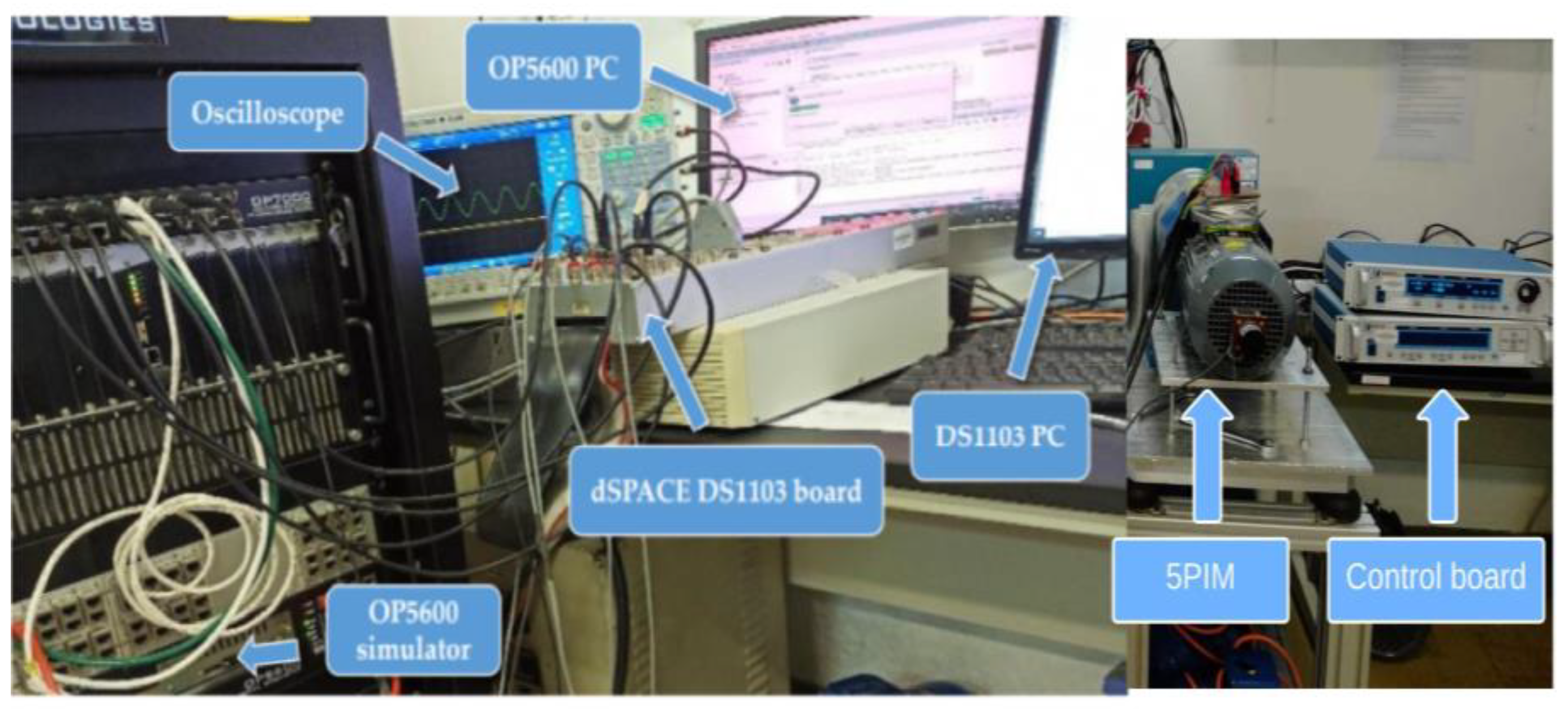
5.1. HIL Setup

The hardware-in-the-loop (HIL) methodology has gained widespread acceptance in critical applications such as hybrid electric vehicles, automotive traction and control systems [34,35,36]. It has many features such as low cost, high safety and higher reliability to verify the control system [5,30,35]. As stated by the authors in [36], if the HIL results are satisfactory, then the same control can be used to investigate the control system experimentally on a real motor drive. The HIL setup is shown in Figure 4 and consists of a dSpace (DSP-1103) board, an OPAL-RT simulator (OP5600) and an oscilloscope. In our application, the suggested control with the examined estimators is implemented on the DSP-1103 board to provide the pulsing signals of the dual NPC converter, while the OeW-5PIM topology fed by the dual NPC inverter is designed in the RT-LAB platform to be executed on OP5600. The switching states generated from the DSP-1103 board are obtained by an FPGA-based digital I/O card, which provides the switching states to control the dual NPC inverter in the RT-LAB platform. The OP6500 then generates feedback voltage and current signals, which are then transmitted to the DSP-1103 board. The switching frequency is set to 5 KHz; meanwhile, the sampling time is set to 50 μs. The electrical and mechanical parameters of the motor are as follows: P = 2.2 kW, R s = 2.9 Ω, R r = 2.7 Ω, L s = 796.4 mH, L r = 796.4 mH, L s r = 785.2 mH, J = 0.007 Kg.m2, F = 0.0018 N.m.s, and n p = 1.

5.2. First Test

To demonstrate the validity of the designed control technique and SC-MRAS estimator, the first conducted test was performed under load torque variations. The reference speed is set to 157 rad/s. Figure 5a presents the estimated speed and rotor speed of the studied OeW-5PIM topology.
It is seen clearly that the estimated speed perfectly tracks the real rotor speed with excellent performance, while the loading changes do not have any effect on the speed tracking. Therefore, the estimation error is close to zero at steady state and attains approximately 0.04% error during the transient as introduced in Figure 5b. This result indicates the accuracy of the designed controller with the used estimator against load disturbances compared to previous works [8,10,37]. Figure 6a shows the d-q rotor flux components of the studied motor. It should be noted that the d-rotor flux is aligned at the reference flux (1 Wb), while the q-rotor rotor flux is maintained at zero. Figure 6b introduces the load torque and the developed torque of the OeW-5PIM topology for the suggested sensorless nonlinear control. It is clear that the developed torque follows the step changes of the reference load torque in the steady state with acceptable ripples compared to the OeW-5PIM topology fed by the dual two-level inverter presented in [2,5,7].
The stator current in the d-q frame is presented in Figure 7a. It is observed that the q-stator current is directly proportional to the developed torque of the studied motor, while the d-stator current is represented as an image for the d-rotor flux component and is equal to a constant value of 2.6 A. At the same time, the amplitude of the stator current in the x-y frame is very small and approximately 0.04 A. In addition, it can be said from Figure 8 that the amplitudes of stator currents in the α-β frame are increased after load torque changes. At the same time, these currents are balanced sinusoidal waveforms, as can be noticed in the zoomed window shown in Figure 8.

5.3. Second Test

To evaluate the performance of the designed sensorless control of the OeW-5PIM topology under different speed values, a special test was performed with constant load torque (4 N.m at 2 s) during high-speed reverse. The used reference speed changes in three stages, from 0 to 157 rad/s, 157 rad/s to 0 rad/s and 0 rad/s to −157 rad/s, as shown in Figure 9a. As presented in this figure, the estimated speed is very close to the real one without any overshoot. At the same time, one can notice that from Figure 9b the estimation error of the SC-MRAS estimator varies quickly from time to time and that the maximum error is approximately 0.04 rad/s, which corresponds to the instant of speed reversal. Consequently, it can be said that the presented SC-MRAS estimator works well against sudden speed changes. The d-rotor flux presents a fast response, and it takes precisely the reference flux (1 Wb) in the whole speed range, whereas the q-rotor flux stays nearly equal to zero, as shown in Figure 10a. The developed torque and reference load torque of the studied motor are presented in Figure 10b. It can be concluded that the developed torque behaves according to the behavior of the drive systems, where the torque amplitude is dependent on the reference speed changes. On the other hand, the stator currents in the α-β frame have a perfect following for the evolution of the drive system, and the studied motor can operate stably at the defined reference speed, as presented in Figure 11.

5.4. Third Test

In order to investigate the feasibility of the designed sensorless control during low-speed reverse, the FLC technique based on the SM controller of the OeW-5PIM topology, including the SC-MRAS estimator, was tested with the motor resistance estimation. The used reference speed changes in three stages, from 0 to 8 rad/s, 8 rad/s to 0 rad/s and 0 rad/s to −8 rad/s, as shown in Figure 12a. It is clear that the estimated speed converges perfectly with the real rotor speed during low/zero speeds. The estimation error is very small, which does not exceed 0.02%, as shown in Figure 12b. Therefore, the SC-MRAS estimator has better tracking speed than the previous works introduced in [8,37]. Furthermore, Figure 13a presents that the d-q rotor flux components indicate an excellent decoupling between the rotor flux and the developed torque, even at a zero/low-speed range. According to Figure 13b, the designed sensorless control provides rapid responses and accurate dynamics of the developed torque of the OeW-5PIM topology for the specified reference speed in this test. On the other hand, it is clearly visible that from Figure 14 the estimated motor resistances converge to their real values within a short time frame compared to the previously introduced methods [4,8,21,22].

5.5. Fourth Test

To investigate the robustness of the designed sensorless controller and estimator under motor parameter changes at a low speed of 8 rad/s with motor resistances estimations, the R s and R r are increased to 50% of their nominal values. Meanwhile, L s and L r are changed to 20% of their nominal value. Indeed, the studied OeW-5PIM topology is started with nominal parameter values R s = 10   Ω , L s = 0.4642   H , R r = 6.3   Ω , L r = 0.4612   H , then the motor parameters are increased to 1.5 R s , 1.2 L s , 1.5 R r and 1.2 L r , as shown in Figure 15 and Figure 16. The motor resistances estimator is activated at 4 s to achieve better performance under motor parameter changes. According to Figure 15a and Figure 16a, it can be concluded that the motor resistances estimator based on the used SC-MRAS estimator can accurately estimate the real values of R s and R r in a low-speed range. The estimated speed and rotor speed are given in Figure 17a and Figure 18a. It is found that the estimated speed still converges to the real rotor speed, but when the values of motor parameters ( R s ,   L s ,   R r and L r ) vary from their real value, the suggested sensorless control becomes unstable during the motor parameter mismatches, which leads to a significant error in the estimation of real rotor speed, as shown in Figure 17b and Figure 18b. To address this problem, the activation of the R s and R r estimators at 4 s are performed. The speed estimation error is reduced to 0.0015 rad/s from 0.008 rad/s in the case of R s estimation and is reduced to 0.0005 rad/s from 0.002 rad/s in the case of R r estimation. Consequently, the obtained results prove satisfactory efficiency and the feasibility of the proposed simultaneous estimation of motor speed,   R s and R r in sensorless nonlinear control based on the SC-MRAS estimator of OeW-5PIM topology.

6. Conclusions

In this paper, an effective sensorless control based on the FLC technique with an SM controller is suggested for the control of an OeW-5PIM topology. In the suggested scheme, the SC-MRAS estimator is presented to ensure an accurate estimation of the speed and rotor flux at a wide range of operation modes. In addition, to ensure the estimation accuracy and minimize the impact of the motor parameter changes on the presented estimator, the paper focused on the estimation of the rotor and stator resistances, especially at the low-/zero-speed range. The correctness and the feasibility of the overall suggested control are successfully tested via the HIL platform under various operating points of the studied motor such as load changes, low-/zero-speed range, parameter mismatches and rotation inversion range. The obtained results prove that the suggested sensorless nonlinear control using the SC-MRAS estimator and resistances estimation provides a very competitive solution for multi-phase motors, particularly the studied topology. On the other hand, this proposed sensorless control is an original application where it is applied in this work for the first time for the present studied motor topology. At the same time, the proposed technique is different from the previous techniques published in [2,3,4,5,6,7,8,9,10,17,18,19,21], where most of these techniques suffer from a common problem of complexity: computational intensiveness. Instead, the proposed method is very simple, and the process of the rotor speed and the motor resistance estimator operates in parallel rather than in a sequential manner.

Author Contributions

Conceptualization, S.K., A.Y.A. and M.A.M.; methodology, S.K., Z.M.S.E. and A.Y.A.; software, S.K.; validation, S.K., M.A.M. and A.Y.A.; formal analysis, S.K., Z.M.S.E., A.Y.A. and M.A.M.; investigation, S.K.; resources, S.K., A.Y.A. and M.A.M.; data curation, S.K. and Z.M.S.E.; writing—original draft preparation, S.K., M.A.M. and A.Y.A.; writing—review and editing, S.K. and Z.M.S.E.; visualization, M.A.M. and A.Y.A.; supervision, A.Y.A. and M.A.M.; project administration, S.K. and M.A.M.; funding acquisition, M.A.M. and Z.M.S.E. All authors have read and agreed to the published version of the manuscript.

Funding

This work has not been funded by any of the organizations.

Data Availability Statement

Not applicable.

Acknowledgments

The authors extend their appreciation to the Deanship of Scientific Research at King Khalid University under for funding this work through General Research Project under Grant number (RGP.2/373/44).

Conflicts of Interest

The author declares no conflict of interest.

References

  1. Liu, G.; Geng, C.; Chen, Q. Sensorless Control for Five-Phase IPMSM Drives by Injecting HF Square-Wave Voltage Signal into Third Harmonic Space. IEEE Access 2020, 8, 69712–69721. [Google Scholar] [CrossRef]
  2. Khadar, S.; Kouzou, A.; Hafaifa, A.; Iqbal, A. Investigation on SVM-Backstepping sensorless control of five-phase open-end winding induction motor based on model reference adaptive system and parameter estimation. Eng. Sci. Technol. Int. J. 2019, 22, 1013–1026. [Google Scholar]
  3. Hosseyni, A.; Trabelsi, R.; Mimouni, M.F.; Iqbal, A.; Alammari, R. Sensorless sliding mode observer for a five-phase permanent magnet synchronous motor drive. ISA Trans. 2015, 58, 462–473. [Google Scholar] [CrossRef] [PubMed]
  4. Holakooie, M.H.; Ojaghi, M.; Taheri, A. Direct Torque Control of Six-phase Induction Motor with a Novel MRAS-Based Stator Resistance Estimator. IEEE Trans. Ind. Electron. 2018, 65, 7685–7696. [Google Scholar] [CrossRef]
  5. Khadar, S.; Abu-Rub, H.; Kouzou, A. Sensorless Field-Oriented Control for Open-End Winding Five-Phase Induction Motor with Parameters Estimation. IEEE Open J. Ind. Electron. Soc. 2021, 2, 266–279. [Google Scholar] [CrossRef]
  6. Echeikh, H.; Trabels, R.; Iqbal, A.; Mimouni, M.F. Adaptive direct torque control using Luenberger-sliding mode observer for online stator resistance estimation for five-phase induction motor drives. Electr. Eng. 2018, 100, 1639–1649. [Google Scholar] [CrossRef]
  7. Khadar, S.; Kouzou, A.; Rezaoui, M.M.; Hafaifa, A. Fault-tolerant sensorless sliding mode control by parameters estimation of an open-end winding five-phase induction motor. Model. Meas. Control. 2019, 92, 6–15. [Google Scholar] [CrossRef]
  8. Taheri, S.; Hai-Peng, R.; Chun-Huan, S. Sensorless Direct Torque Control of the Six-Phase Induction Motor by Fast Reduced Order Extended Kalman Filter. Complexity 2020, 1–10. [Google Scholar] [CrossRef]
  9. Echeikh, H.; Trabels, R.; Iqbal, A.; Mimouni, M.F. Real time implementation of indirect rotor flux-oriented control of a five-phase induction motor with novel rotor resistance adaption using sliding mode observer. J. Frankl. Inst. 2018, 355, 2112–2141. [Google Scholar] [CrossRef]
  10. Mossa, A.M.; Quynh, N.; Echeikh, H.; Do, T.D. Deadbeat-Based Model Predictive Voltage Control for a Sensorless Five-Phase Induction Motor Drive. Math. Probl. Eng. 2020, 2020, 30. [Google Scholar] [CrossRef]
  11. Bojoi, R.; Cavagnino, A.; Tenconi, A.; Vaschetto, S. Control of shaft-line-embedded multiphase starter/generator for aero-engine. IEEE Trans. Ind. Electron. 2016, 63, 641–652. [Google Scholar] [CrossRef]
  12. De-Lillo, L.; Empringham, L.; Wheeler, P.; Khwan, S.; Gerada, C.; Othman, M.; Huang, X. Multiphase power converter drive for fault-tolerant machine development in aerospace applications. IEEE Trans. Ind. Electron. 2010, 57, 575–583. [Google Scholar] [CrossRef]
  13. Bojoi, R.; Cavagnino, A.; Cossale, M.; Tenconi, A. Multiphase starter generator for a 48 V mini-hybrid power train: Design and testing. IEEE Trans. Ind. Appl. 2016, 52, 1750–1758. [Google Scholar]
  14. Khadar, S.; Kouzou, A.; Benguesmia, H. Fuzzy Stator Resistance Estimator of Induction Motor fed by a Three Levels NPC Inverter Controlled by Direct Torque Control. In Proceedings of the 2018 International Conference on Applied Smart Systems (ICASS), Medea, Algeria, 24–25 November 2018; IEEE: Piscataway, NJ, USA, 2018. [Google Scholar]
  15. Umbría, F.; Gordillo, F.; Estern, F.G.; Salas, F.; Portillo, R.C.; Sergio, V. Voltage balancing in three-level neutral-point-clamped converters via Luenberger observer Control. Eng. Pract. 2014, 25, 36–44. [Google Scholar] [CrossRef] [Green Version]
  16. Priestley, M.; Farshadnia, M.; Fletcher, J.E. FOC transformation for single open-phase faults in the five-phase open-end winding topology. IEEE Trans. Ind. Electron. 2020, 67, 842–851. [Google Scholar] [CrossRef]
  17. Mavila, P.C.; Rajeevan, P.P. A new direct torque control scheme for five phase open-end winding induction motor drives with reduced DC voltage requirement. In Proceedings of the 2020 IEEE International Conference on Power Electronics, Smart Grid and Renewable Energy (PESGRE2020), Cochin, India, 2–4 January 2020; IEEE: Piscataway, NJ, USA, 2020; pp. 1–6. [Google Scholar]
  18. Jorge, R.; Federico, B.; Manuel, A.; Cristina, M.; Raul, G. Online Estimation of Rotor Variables in Predictive Current Controllers: A Case Study Using Five-Phase Induction Machines. IEEE Trans. Ind. Electron. 2016, 63, 5348–5356. [Google Scholar]
  19. Riveros, J.; Barrero, F.; Levi, E.; Durán, M.; Toral, S.; Jones, M. Variable speed five-phase induction motor drive based on predictive torque control. IEEE Trans. Ind. Electron. 2013, 60, 2957–2968. [Google Scholar] [CrossRef]
  20. Bagheriab, M.; Naseradinmousavib, P.; Krstić, M. Feedback linearization-based predictor for time delay control of a high-DOF robot manipulator. Automatica 2019, 108, 108485. [Google Scholar] [CrossRef]
  21. Regaya, C.B.; Farhani, F.; Zaafouri, A.; Chaari, A. A novel adaptive control method for induction motor based on Backstepping approach using dSpace DS 1104 control board. Mech. Syst. Signal Processing. 2018, 100, 466–481. [Google Scholar] [CrossRef]
  22. Van, T.P.; Tien, D.V.; Leonowicz, Z.; Jasinski, M.; Sikorski, T.; Chakrabarti, P. Online Rotor and Stator Resistance Estimation Based on Artificial Neural Network Applied in Sensorless Induction Motor Drive. Energies 2020, 13, 4946. [Google Scholar]
  23. Sahraoui, K.; Kouzi, K.; Ameur, A. A Robust Sensorless Iterated Extended Kalman Filter for Electromechanical Drive State Estimation. Electroteh. Electron. Autom. 2017, 65, 46–53. [Google Scholar]
  24. Shinohara, K.; Nagano, T.; Arima, H.; Mustafa, W.Z.W. Online tuning method of stator and rotor resistances in both motoring and regenerating operations for vector-controlled induction machines. Elect. Eng. Jpn. 2001, 135, 56–64. [Google Scholar] [CrossRef]
  25. Teja, A.V.R.; Verma, V.; Chakraborty, C. A new formulation of reactive-power-based model reference adaptive system for sensorless induction motor drive. IEEE Trans. Ind. Electron. 2015, 62, 6797–6808. [Google Scholar] [CrossRef]
  26. Rashed, M.; Stronach, A.F. A stable back-EMF MRAS-based sensorless low-speed induction motor drive insensitive to stator resistance variation. Proc. IEEE Electr. Power Appl. 2004, 151, 685–693. [Google Scholar] [CrossRef]
  27. Verma, V.; Chakraborty, C. New series of MRAS for speed estimation of vector-controlled induction motor drive. In Proceedings of the IECON 2014-40th Annual Conference of the IEEE Industrial Electronics Society, Dallas, TX, USA, 29 October–1 November 2014; IEEE: Piscataway, NJ, USA, 2014; pp. 755–761. [Google Scholar]
  28. Korzonek, M.; Tarchala, G.; Orlowska-Kowalska, T. Simple Stability Enhancement Method for Stator Current Error-Based MRAS-Type Speed Estimator for Induction Motor. IEEE Trans. Ind. Electron. 2020, 67, 5854–5866. [Google Scholar] [CrossRef]
  29. Kojabadi, H.M. Active power and MRAS based rotor resistance identification of an IM drive. Simul. Model. Pract. Theory 2009, 17, 376–389. [Google Scholar] [CrossRef]
  30. Merabet, A.; Tanvir, A.; Beddek, K. Speed control of sensorless induction generator by artificial neural network in wind energy conversion system. IET Renew. Power Gener. 2016, 10, 1597–1606. [Google Scholar] [CrossRef]
  31. Kumar, A.; Ramesh, T. MRAS speed estimator for speed sensorless IFOC of an induction motor drive using fuzzy logic controller. In Proceedings of the 2015 International Conference on Energy, Power and Environment: Towards Sustainable Growth (ICEPE), Shillong, India, 12–13 June 2015; IEEE: Piscataway, NJ, USA, 2015. [Google Scholar]
  32. Korzonek, M.; Orłowska-Kowalska, T. Comparative Stability Analysis of Stator Current Error-based Estimators of Induction Motor Speed. Power Electron. Drives 2018, 3, 187–203. [Google Scholar] [CrossRef] [Green Version]
  33. Oh, S.C. Evaluation of motor characteristics for hybrid electric vehicles using the hardware-in-the-loop concept. IEEE Trans. Veh. Technol. 2005, 54, 817–824. [Google Scholar] [CrossRef]
  34. Yoon, M.; Lee, W.; Sunwoo, M. Development and implementation of distributed hardware-in-the-loop simulation for automotive engine control systems. Int. J. Automot. Technol. 2005, 6, 107–117. [Google Scholar]
  35. Tavana, N.R.; Dinavahi, V. Real-time nonlinear magnetic equivalent circuit model of induction machine on FPGA for hardware-in-the-loop simulation. IEEE Trans. Energy Convers. 2016, 31, 520–530. [Google Scholar]
  36. Zhang, Y.; Huang, P.; Yang, H. Hardware-in-the-Loop Real-time Simulation for Speed-Sensorless Vector Control of High-Power Induction Motor. In Proceedings of the 2019 22nd International Conference on Electrical Machines and Systems (ICEMS), Harbin, China, 11–14 August 2019; IEEE: Piscataway, NJ, USA, 2019. [Google Scholar]
  37. Zorgani, Y.A.; Koubaa, Y.; Boussak, M. MRAS state estimator for speed sensorless ISFOC induction motor drives with Luenberger load torque estimation. ISA Trans. 2016, 61, 308–317. [Google Scholar] [CrossRef]
Figure 1. Power circuit of OeW-5PIM topology with a single DC source.
Machines 11 00469 g001
Figure 2. Simplified schematic for the proposed control of OeW-5PIM.
Machines 11 00469 g002
Figure 3. General structure of SC-MRAS estimator.
Machines 11 00469 g003
Figure 4. Hardware-in-the-loop setup.
Machines 11 00469 g004
Figure 5. OeW-5PIM performance under load torque variations (a) speeds responses; (b) estimation error.
Machines 11 00469 g005
Figure 6. OeW-5PIM performance under load torque variations (a) d-q rotor flux responses; (b) developed torque.
Machines 11 00469 g006
Figure 7. OeW-5PIM performance under load torque variations (a) stator currents in d-q frames; (b) stator currents in x-y frames.
Machines 11 00469 g007
Figure 8. The stator currents in α-β frames.
Machines 11 00469 g008
Figure 9. OeW-5PIM performance under during high-speed reverse (a) speeds responses; (b) estimation error.
Machines 11 00469 g009
Figure 10. OeW-5PIM performance during high-speed reverse (a) d-q rotor flux responses; (b) developed torque.
Machines 11 00469 g010
Figure 11. The stator currents in α-β frames.
Machines 11 00469 g011
Figure 12. OeW-5PIM performance during low-speed reverse (a) speeds responses; (b) estimation error.
Machines 11 00469 g012
Figure 13. OeW-5PIM performance during low-speed reverse (a) d-q rotor flux responses; (b) developed torque.
Machines 11 00469 g013
Figure 14. The motor resistances (a) rotor resistance; (b) stator resistance.
Machines 11 00469 g014
Figure 15. The stator parameters (a) stator resistance; (b) stator inductance.
Machines 11 00469 g015
Figure 16. The rotor parameters (a) rotor resistance; (b) rotor inductance.
Machines 11 00469 g016
Figure 17. OeW-5PIM performance under rotor parameter changes (a) speeds responses; (b) estimation error.
Machines 11 00469 g017
Figure 18. OeW-5PIM performance under stator parameter changes (a) speeds responses; (b) estimation error.
Machines 11 00469 g018
Disclaimer/Publisher’s Note: The statements, opinions and data contained in all publications are solely those of the individual author(s) and contributor(s) and not of MDPI and/or the editor(s). MDPI and/or the editor(s) disclaim responsibility for any injury to people or property resulting from any ideas, methods, instructions or products referred to in the content.

