Article

Study on Wear Properties of the Graphite-Sealing Surfaces in a Triple Eccentric Butterfly Valve Based on EDEM-Fluent Coupling

1
School of Petrochemical Technology, Lanzhou University of Technology, Lanzhou 730050, China
2
Machinery Industry Pump and Special Valve Engineering Research Center, Lanzhou University of Technology, Lanzhou 730050, China
*
Author to whom correspondence should be addressed.
Machines 2023, 11(4), 463; https://doi.org/10.3390/machines11040463
Submission received: 14 February 2023 / Revised: 25 March 2023 / Accepted: 28 March 2023 / Published: 7 April 2023
(This article belongs to the Section Friction and Tribology)

Abstract

:
When using valves and pipes, erosion wear is a major issue. Erosion wear can result in equipment shutdown, material replacement, and other issues, as well as the failure of sealing surfaces. The depth of erosion wear is primarily determined by particle velocity, particle size, target material, and use conditions. A combination of the discrete element method (DEM) and computational fluid dynamics (CFD) was used in this study. The dynamic process of particle collision with the sealing surface is also considered. The wear depth was then calculated using Archard’s abrasive wear theory. The erosion wear process of the graphite-sealing surface by gas-solid two-phase flow medium is numerically simulated in a high-temperature triple eccentric butterfly valve using the above theory and method. The erosion wear patterns of graphite-sealing surfaces were investigated under various particle velocities, particle sizes, target materials, and service conditions. The findings indicate that particle velocity and particle size are positively related to wear rate. Soft target wear depth is greater than hard target wear depth. The wear depth decreases as the ambient temperature rises. As a result, graphite has excellent resistance to erosion and wear at high temperatures. When feeding, however, particle velocity and particle size must be considered. The erosion wears characteristics of a high temperature three eccentric butterfly valve investigated in this paper can be used to optimize erosion wear prevention.

1. Introduction

There are currently about 1000 blast furnaces in China, producing over 700 million tons of pig iron per year. Up to now and for a long time to come, blast furnaces will remain the most competitive ironmaking process. In addition, the blast furnace is also widely used in the heat tracing system of molten salt photothermal power generation to provide the heat source for steam heat tracing. A high-temperature triple eccentric butterfly valve is the best device for regulating the flow, cutting off, or connecting the fluid on the pipeline. It is commonly used in the coal chemical industry, petrochemical industry, metallurgy, and high-temperature molten salt photothermal power industry. Therefore, it is widely used in blast furnace iron-making and molten salt photothermal power generation processes. Additionally, applying a metal-graphite laminate seal to a triple eccentric butterfly valve can further improve the sealing performance of a triple eccentric butterfly valve [1,2]. However, when the blast furnace gas passes through the butterfly valve [3], solid phase particles such as iron powder, ore, coke, and lime in the blast furnace gas mixture will inevitably hit the sealing surface [4,5,6]. It leads to wear on the graphite-sealing surface. In turn, it affects the sealing performance of the three-eccentric multi-level sealing butterfly valve. Therefore, this paper will analyze the process of erosion and wear of valve sealing surfaces by solid phase particles. In this paper, the wear characteristics [7,8,9] of high-temperature triple eccentric butterfly valve during the transportation of blast furnace gas, the particle distribution [10] and the particle flow rate [11,12], particle size [13], temperature and other factors on wear are studied based on the coupled CFD-DEM theory. Firstly, in the study of erosive wear occurring in contact between solid phase particles and graphite-sealing surfaces. The particle-wall contact process is calculated based on the soft sphere model. Additionally, then the motion law and kinematic mechanical properties of the particle-wall collision process are obtained [14,15]. Secondly, when the blast furnace gas is transported, the solid phase particles are subjected to the action of the gas phase flow field, which cuts the graphite surface. Theoretical analysis of the cutting action of solid phase particles on graphite surfaces based on the Archard abrasive wear model [16,17]. Finally, the interaction between solid and gas phases is analyzed based on CFD-DEM theory. Combining the above theories and methods, the wear law of graphite-sealing surface is obtained.
A method based on the inter-coupling of the Archard abrasive wear model, softball model, and CFD-DEM theory is proposed to calculate erosion wear. It is used to predict the wear of graphite-sealing surfaces when subjected to erosive wear by solid phase particles in blast furnace gas, the particle movement, and to study the effect of different media flow rates, particle sizes, and temperatures on the wear condition. Most of the previous research focuses on the two-phase flow wear in pumps. No scholars have ever applied the DEM-CFD method to high-temperature triple eccentric butterfly valves. This study is the first time to apply DEM-CFD to high-temperature triple eccentric butterfly valves. Considering the influence of particle shape size, particle distribution, particle strength, drag force, lift force, and other factors on two-phase flow wear, it provides a reference for the safe and stable operation of a high-temperature three-eccentric butterfly valve in the future.

2. Theoretical Foundation

When transporting blast furnace gas, the solid phase particles inside are affected by the flow field forces and will inevitably collide with the graphite-sealing surface, and the collision process may involve wear, erosion, and corrosion [18,19]. Where erosion is the loss of surface material caused by the mechanism of cutting damage. Wear is the loss of material caused by solid phase particles rubbing against the target surface. Additionally, then corrosion, on the other hand, is a chemical process between the medium and the wall. The failure of the seal in this study is dominated by erosive wear. Since both erosion and abrasion are mechanical wear processes and have many similarities, the process of solid phase particles eroding the sealing surface is the focus of this study.

2.1. Mathematical Model of Continuous Phase and Discrete Phase

(1)
Mathematical model of continuous phase based on Eulerian multiphase flow theory
The Eulerian multiphase flow model can describe the interaction between two phases well, so it is widely used in multiphase flow research. In the Eulerian model, there is a mass transfer between the two phases. Based on the Eulerian multiphase flow model, the control equation for the continuous phase is described as follows:
(a)
The continuity equation of the q phase is as follows:
t ( α q ρ q ) + ( α q ρ q v q ) = p = 1 n ( m ˙ p q m ˙ q p ) + S q ,
where, m ˙ p q is the mass transfer from p phase to q phase, m ˙ q p is the mass transfer from q phase to p phase.
(b)
The momentum equation of phase q:
t ( α q ρ q v q ) + ( α q ρ q v q v q ) = α q p + τ = q + α q ρ q g + p = 1 n ( R p q + m ˙ p q v p q m ˙ q p v q p ) + ( F q + F l i f t , q + F w l , q + F v m , q + F t d , q ) ,
where, the first term on the right side of the equation is the pressure. The second item is the shear force. The third item is gravity. The fourth term is the change in momentum due to mass transfer between the two phases. The fifth term is the interphase force applied. R p q is the interaction force between the two phases. R p q depends on the friction, pressure, etc., and contains the drag force model. v p q is the interphase velocity. F q is the external volume force. F l i f t , q is the lift force. F w l , q is the wall lubrication force. F v m , q is the virtual mass force. F t d , q is the turbulent dissipative force.
(c)
q term energy equation takes the specific enthalpy form:
t ( α q ρ q h q ) + ( α q ρ q v q h q ) = α q d p q d t + τ = q : u q q q + S q + p = 1 n ( Q p q + m ˙ p q h p q m ˙ q p h q p ) j h j , q J j , p ,
where, q q is the heat flow density. Sq is the source term, such as chemical reaction or radiative heat transfer. Q p q is the interphase heat transfer strength. The last term on the right side of the equation is the energy transfer for component diffusion.
Numerical simulations using the continuous phase mathematical model described above allow the distribution of fluid pressure and velocity in the flow channel to be obtained and, thus, the initial motion conditions of the particles.
(2)
Discrete phase mathematical model based on DEM theory
DEM is a commonly used theory in the study of discontinuous particle motion laws; it is a numerical analysis method to analyze the contact force and motion of discrete term particles.
The equation of motion of the discrete phase can be expressed as follows:
m i d v i d t = F D + F C + G ,
I i d ω i d t = T i ,
where, t is the solid phase particle movement time. F C and G are the collision force and gravity of the solid phase particles. m i and v are the mass and velocity of the solid phase particles, I i , ω i , and T i are the rotational inertia, angular velocity, and torque of the solid phase particles. F D is the interaction force between fluid and solid phase particles. The expressions are as follows:
F D = F D R A G + F P + F B + F V R + F B T + F S A F F + F M A G ,
where, the right side of the equation is, in order, the drag force, pressure gradient force, buoyancy force, virtual mass force, Basset force, Saffman lift force, and Magnus force.
In this study, the pressure gradient and velocity gradient change greatly when the solid-phase particles flow from the unconfined space to the confined flow channel, so the pressure gradient force, Saffman lift force, and Magnus force need to be considered. Since the solid particle density is much larger than the blast furnace gas density, the virtual mass force and Basset force can be neglected.

2.2. Calculation of Particle-Wall Kinematics Based on Soft Sphere Model

When the blast furnace gas mixture is transported to the graphite seal, the particle solid phase collides with the graphite contact. The contact process of particle-wall collision is studied. First, it is necessary to study the collision force. Figure 1 shows the contact process between particle A and particle B (B is a particle or wall) [18].
The softball model is used to calculate the impact force. The model mainly uses elastic and damping coefficients to simplify the contact process and assumes that the parameters remain constant during the contact process. The softball model is shown in Figure 2.
Equations for calculating normal and tangential forces based on the softball model are as follows:
F n = k n Δ x + C n v n ,
F t = min ( μ F n , k t v t d t + C t v t ) ,
where ∆x is the solid phase particle overlap length, k n , and k t are the normal and tangential spring coefficients between A and B, v n and v t are the normal and tangential velocities, and C n and C t are the normal and tangential damping coefficients. μ is the A and B friction coefficient.
During the contact between the solid phase particles and the graphite-sealing surface, there will be many solid phase particles touching the graphite-sealing surface at the same time, so the total collision force and total torque acting on particle A are as follows:
F A = m ( F n + F t ) ,
T A = m ( r A n × F t ) ,
where F A is the total collision force of solid-phase particles, T A is the total torque of solid-phase particles, m is the number of solid-phase particles in contact with the graphite-sealing surface at the same time, r A is the solid-phase particle radius, and n is the unit vector from particle A to wall B.
Considering the solid-phase particles as ideal rigid bodies, the exact trajectory of the solid-phase particles can be calculated by using the DEM theory. Combined with the soft sphere model, the motion law, and kinetic characteristics of the collision process between the solid phase particles and the wall can be obtained.
F A = 1 6 π d A 3 d p d x ,
F S A F F = 1.6155 d A 2 ρ L μ L ( v L v A ) | d v L d y | ,
F M A G = π 8 d A 3 ρ L [ ω × ( v A v L ) ] [ 1 + θ ( R ) ] ,
F B = ρ L g V A ,
G = m A g ,
where dA is the diameter of solid phase particles, ρL is the density of blast furnace gas, μL is the viscosity of blast furnace gas, vL is the velocity of blast furnace gas, vA is the velocity of solid phase particles, VA is the volume of solid phase particles, and mA is the mass of solid phase particles.

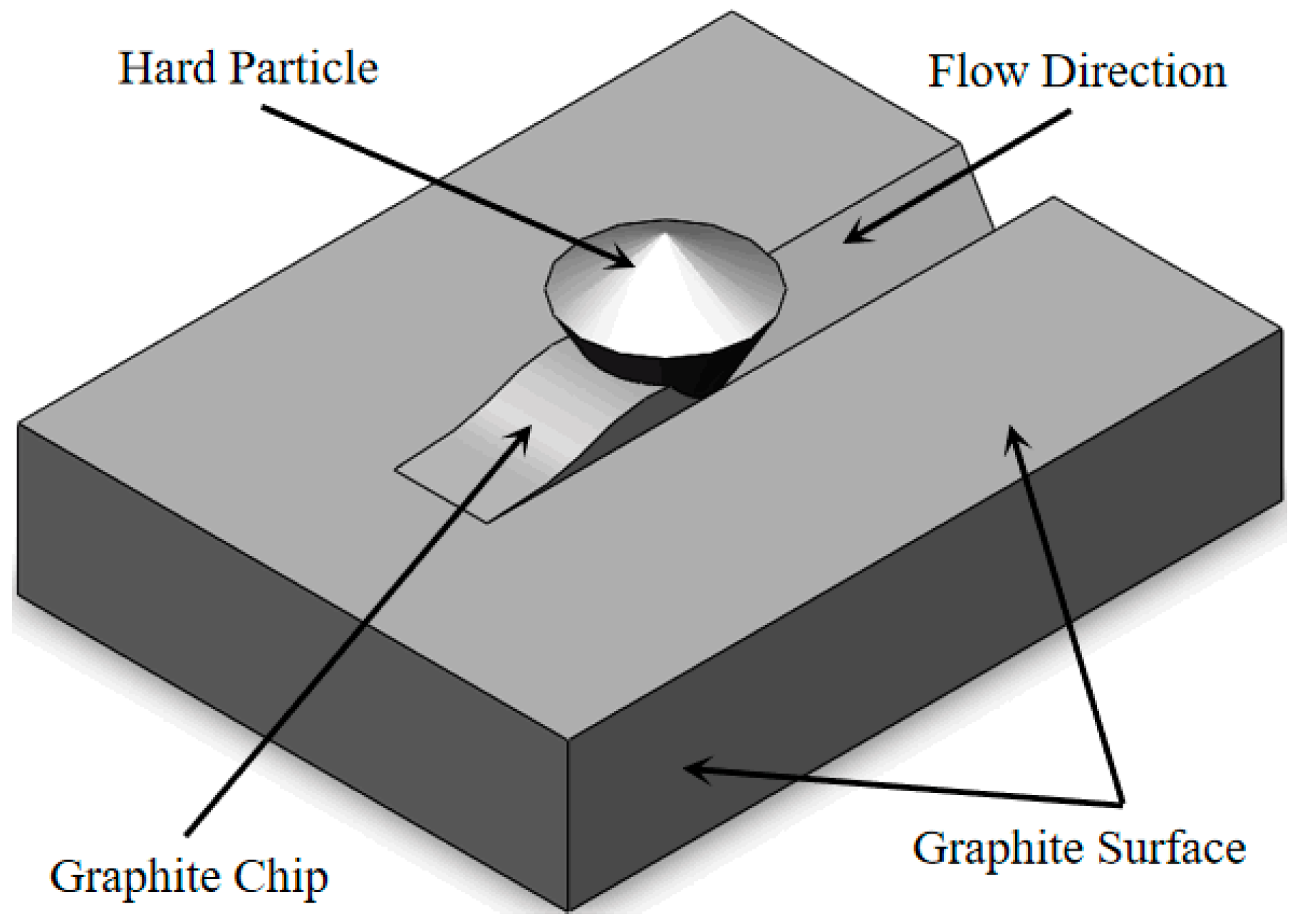
2.3. Solid Phase Particle Erosion and Wear Mechanism

During the media transport, the solid phase particles are subjected to the action from the blast furnace gas flow field. It is pressed into the graphite surface along the flow normal direction. At the same time, it cuts the graphite surface along the flow tangential direction with the movement of blast furnace gas. The metal-graphite laminate seal structure of the triple eccentric butterfly valve is shown in Figure 3. The mechanism of solid phase particles eroding the material surface is shown in Figure 4.
The idea of calculating graphite seal surface wear based on Archard’s wear model assumes the following:
(1)
Graphite seal surface wear is proportional to the abrasive friction distance;
(2)
Graphite seal surface wear is proportional to the normal load value;
(3)
Graphite seal surface wear is inversely proportional to the surface hardness.
From the above assumptions, the equation for abrasive wear based on the Archard model can be obtained as follows:
V = k N H x ,
The equation for adhesive wear is obtained as follows:
V = k N 3 δ x ,
where V is the graphite wear volume, k is the graphite wear coefficient, N is the normal load on the graphite-sealing surface, x is the relative sliding distance between the solid phase particles and the graphite-sealing surface, H is the hardness of graphite, and δ indicates the compressive yield limit of graphite. From Equation (1), the wear volume V of graphite is related to the normal load N on the graphite-sealing surface, the relative sliding distance x between the solid phase particles and the graphite-sealing surface, and the characteristics of the graphite-sealing surface.
Based on Eulerian multiphase flow theory and DEM theory, combined with the soft sphere model at the same time, parameters such as normal load N and relative sliding distance x during the collision between solid phase particles and graphite-sealing surface are obtained. Finally, the general law of erosion and wear of graphite-sealing surface inside the triple eccentric butterfly valve is obtained by combining with Archard’s abrasive wear theory.

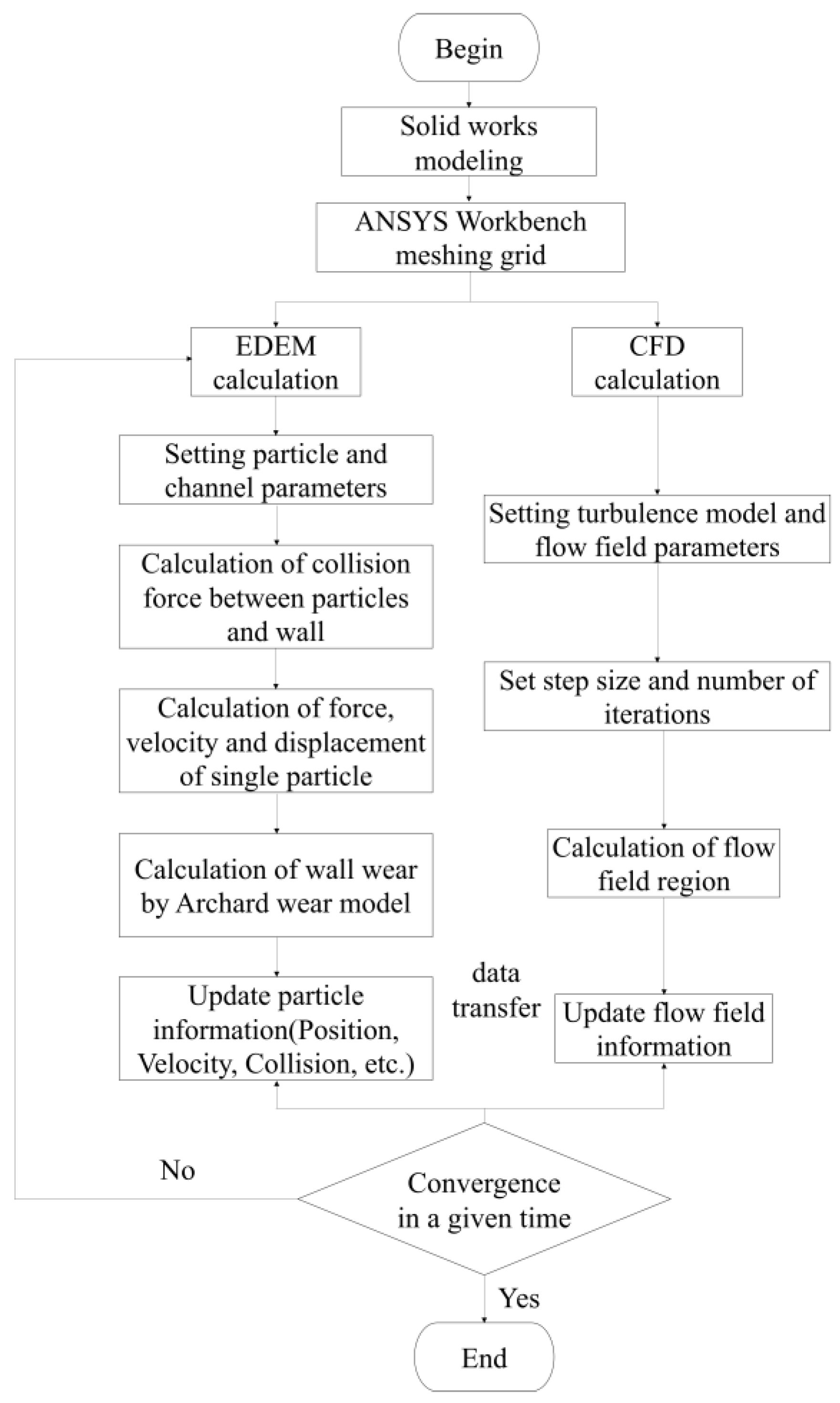
3. Wear Rate Study of Seal Sub Based on CFD-DEM Coupling

Based on the above theoretical derivation, the coupled CFD-DEM solution method is proposed. The coupled simulation flow chart is shown in Figure 5.
First, the continuous phase is discretized using a fluid cell grid and solved by the CFD method to obtain a stable solution. The coupling module starts to calculate the correlation velocity between the blast furnace gas and the solid phase particles and starts to calculate the interaction force. Subsequently, based on DEM theory, the trajectory of solid phase particles is calculated in EDEM, and if the particles are in contact during the motion, the particle contact model will be activated. The gas-solid two-phase flow in the above coupled CFD-DEM solution process is an unsteady fluid due to the stochastic nature of the solid-phase particle-graphite-sealing surface collision process. Finally, through the above-coupled solution method, the trajectory of the particle can be obtained, and the relevant data involved in the contact between the particle and the wall can be obtained. Based on the erosion wear theory, the final wear depth on the graphite-sealing surface is obtained.

3.1. Working Conditions and Material Parameters

The sealing structure of the triple eccentric butterfly valve adopts the form of metal-graphite—metal lamination, and the working parameters are shown in Table 1. The metal material of the valve body and seal ring is A351 CF8 (Muyan Special Alloy Co., Ltd., Shanghai, China), the soft material of the seal ring is graphite, and the material of the valve stem and sleeve is Inconel 625 (Muyan Special Alloy Co., Ltd., Shanghai, China).

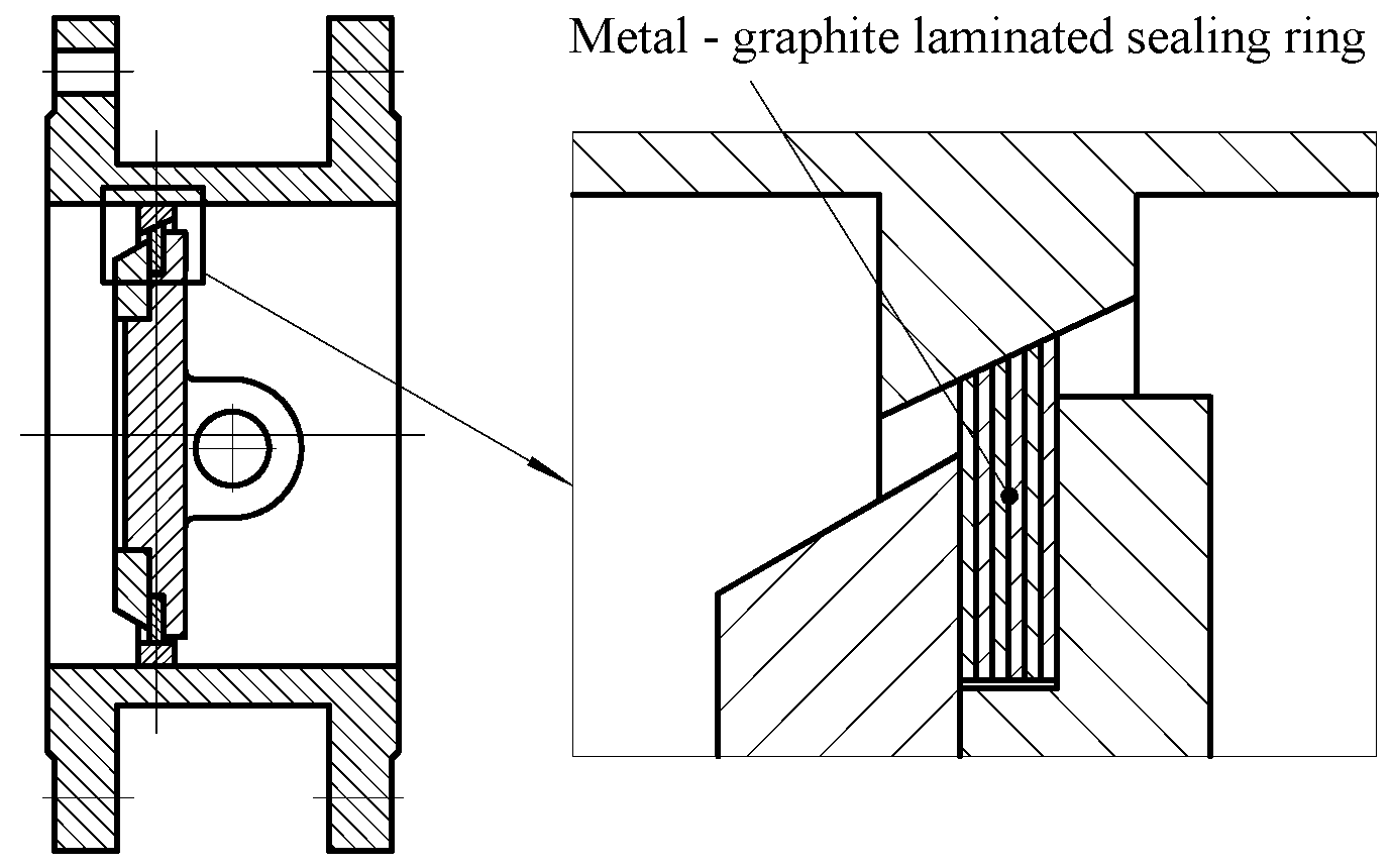
3.2. Flow Channel Model and Particle Model

In the study of erosion wear of triple eccentric butterfly valves, the wear of the graphite-sealing surface is mainly studied, so the geometric model is reasonably simplified. Many small process structures, such as chamfers, small holes, and threads, are removed from the model to ensure calculation accuracy. In the fully open case, 5 times more pipe in front of the valve and 10 times more pipe diameter after the valve are added to ensure full fluid flow, and the model is modeled in reverse. A schematic of the fluid domain is shown in Figure 6.
For abrasive wear, parameters such as the shape and size of the particles influence the wear depth, so a 3D model of the solid phase particles is modeled as shown in Figure 7 to establish a 3D model of the particle shape, considering the particle shape parameters. Additionally, the model file is imported into the EDEM software (DEM Solutions, Edinburgh, UK) for automatic filling, and the combination of multiple spherical particles is used to fill it into a 3D model of approximate particles [20]. For ease of calculation, all the particles in the simulation have the same shape, but the particle size distribution in each simulation is set according to the normal distribution. That is, each simulated particle has the same shape but a different size.

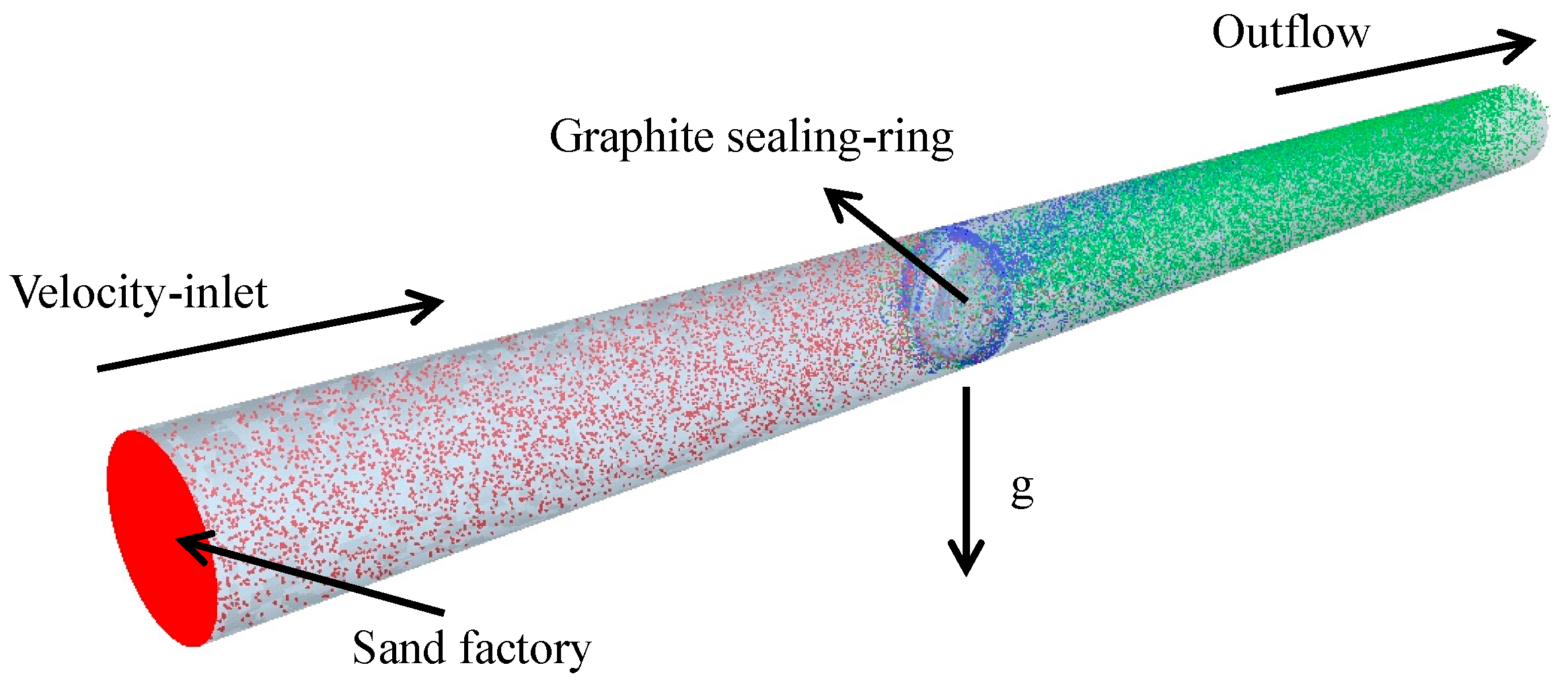
3.3. Loads and Boundary Conditions

According to the actual working conditions, three eccentric butterfly valve and their pipeline particle size are taken as 0.14~0.30 mm, the inlet flow rate v is taken as 4~12 m/s, particle mass flow rate is 0.002 kg/s. The contact model of particle-particle, particle-metal, and particle-graphite in EDEM was Hertz–Mindlin (no slip), and the erosion model was Archard wear. Give the downward gravitational acceleration 9.81 m/s2. Total simulation time 1 s. The various parameter Settings are shown in Table 2 [21,22].

3.4. Graphite Seal Surface Wear Analysis

The outer ring surface of the seal is divided into the following four regions: upper transition surface, lower transition surface, straight edge surface, and oblique cone surface, respectively. Its circumferential nodes are extracted separately, and node information is extracted at an interval of 15°, and the distribution of monitoring points is shown in Figure 8.
Additionally, the seal is divided into laminate styles according to the actual situation to form the following three graphite seals: graphite 1, graphite 2, and graphite 3, respectively, as shown in Figure 9.
When the two-phase flow of the butterfly valve is numerically simulated based on the coupled CFD-DEM method, the velocity cloud obtained at the blast furnace gas velocity of 4 m/s is shown in Figure 10.
Blast furnace gas flows from the inlet at a uniform rate up to the fully open valve flap. Due to the valve flap blocking gas velocity reduced to about 3 m/s, then flowing through the valve seat, the diameter of the valve seat is smaller than the diameter of the pipe, forming a throttle. Additionally, due to the sudden shrinkage of the pipe diameter, the flow channel area is reduced according to the fluid continuity gas velocity increases rapidly, and the gas phase in the valve after the velocity reaches the maximum, for about 9 m/s. Additionally, the velocity near the pipe wall not far behind the valve is close to zero.
The flow field information solved in Fluent (Fluent Inc., New York, NY, USA) is imported into EDEM and then solved, and the imported flow field vector diagram is shown in Figure 11.
Fluid flows in at a speed of 4 m/s. After contacting the sealing surface, a hysteresis point is formed, and the fluid spreads in all directions along the sealing ring face. Additionally, after passing through the valve throttle, the flow velocity in the middle part of the flow channel is greater than 10 m/s, and the flow velocity in the part near the pipe wall is less than the inflow velocity.
The particle distribution cloud is obtained as shown in Figure 12.
The solid phase particles in the blast furnace gas flow into the butterfly valve uniformly at a speed of 4 m/s. When the flow reaches the valve flap, the speed of some solid phase particles decreases to zero after contact with the valve flap because of the collision between the solid phase particles and the valve flap. From Figure 12, it can be seen that because of the gas phase and gravity, the particles will tend to go downward to the point of forming a pile-up at the valve, and a region of reduced flow velocity will be formed after the valve. The velocity of solid phase particles after passing through the valve is stable in a certain area at about 3 m/s.
A wear cloud is obtained, as shown in Figure 13.
The maximum wear depth of the seal’s surface at a flow rate of 4 m/s is 8.14 × 10⁻⁸ mm, located on the graphite 1 of the graphite seal surface on the straight side of the seal. The simulation time is 1 s, then the maximum wear rate of graphite can be calculated as 2.567 mm/a; that is, the graphite seal surface is worn by erosion under full open working conditions for one year, and the wear depth will reach 2.567 mm.
Three of the graphite-sealing surfaces are shown in Figure 14 as a percentage of wear.
Among them, graphite 1 has the largest wear, and graphite 3 has the smallest wear. This is because the butterfly valve is a triple eccentric butterfly valve, and the graphite-sealing surface is not a regular circular ring, but a conical ring, which leads to the largest wear of graphite 1, which has a large contact area with the medium, and the smallest wear of graphite 3, which has the smallest contact area.

4. Parameters Affecting Erosive Wear of Solid Phase Particles

Based on the theoretical derivation, erosion wear is related to particle transport speed and particle diameter size, and secondly, target material properties and fluid temperature also influence erosion wear.

4.1. Effect of Transport Speed on Wear Rate

The wear depth rate is related to the particle transport speed [23]. Also, the transport speed affects the capacity. Low transport speed, low capacity, does not meet production needs; too high transport speed, increased wear, and tear. Therefore, the selection of transportation speed needs to consider the above factors.
Considering the effect of solid phase particles on the seal surface wear at different flow rates, the wear depth of graphite seal surface at 4 m/s, 6 m/s, 8 m/s, 10 m/s, and 12 m/s flow rates, respectively, the cloud chart of the wear depth distribution at different flow rates is shown in Figure 15.
As can be seen from Figure 15, the wear depth in the middle part of the straight edge surface is significantly smaller than the wear depth on the left and right sides. This is due to the fluid movement to the seal’s surface when the hysteresis point, the fluid will be along the seal ring to spread around, as the impact angle increases, and the wear depth shows a trend of first increasing and then decreasing. Its maximum value appears around monitoring points 16–17 and 21–22, which indicates the existence of an impact angle that makes the wear rate maximum when the cutting effect is most significant. So, the impact angle at the hysteresis point is 90° (monitoring point 19), and the wear will be less than the middle part left and right.
The total wear line diagram of the seal’s surface at different speeds is shown in Figure 16. Wear occurs after the particles encounter the graphite-sealing surface, and the minimum velocity of the particles is 7.13 m/s before the particles encountered the graphite-sealing surface. After the contact between the particles and the graphite-sealing surface, the minimum velocity is 2.99 m/s due to the collision between the particles and the sealing surface, and after the contact, the slope h* = constant. As can be seen from Figure 17, the total wear depth of the sealing surface as a function of time is approximated as a monotonically increasing function, and the wear depth rate is proportional to the flow rate.

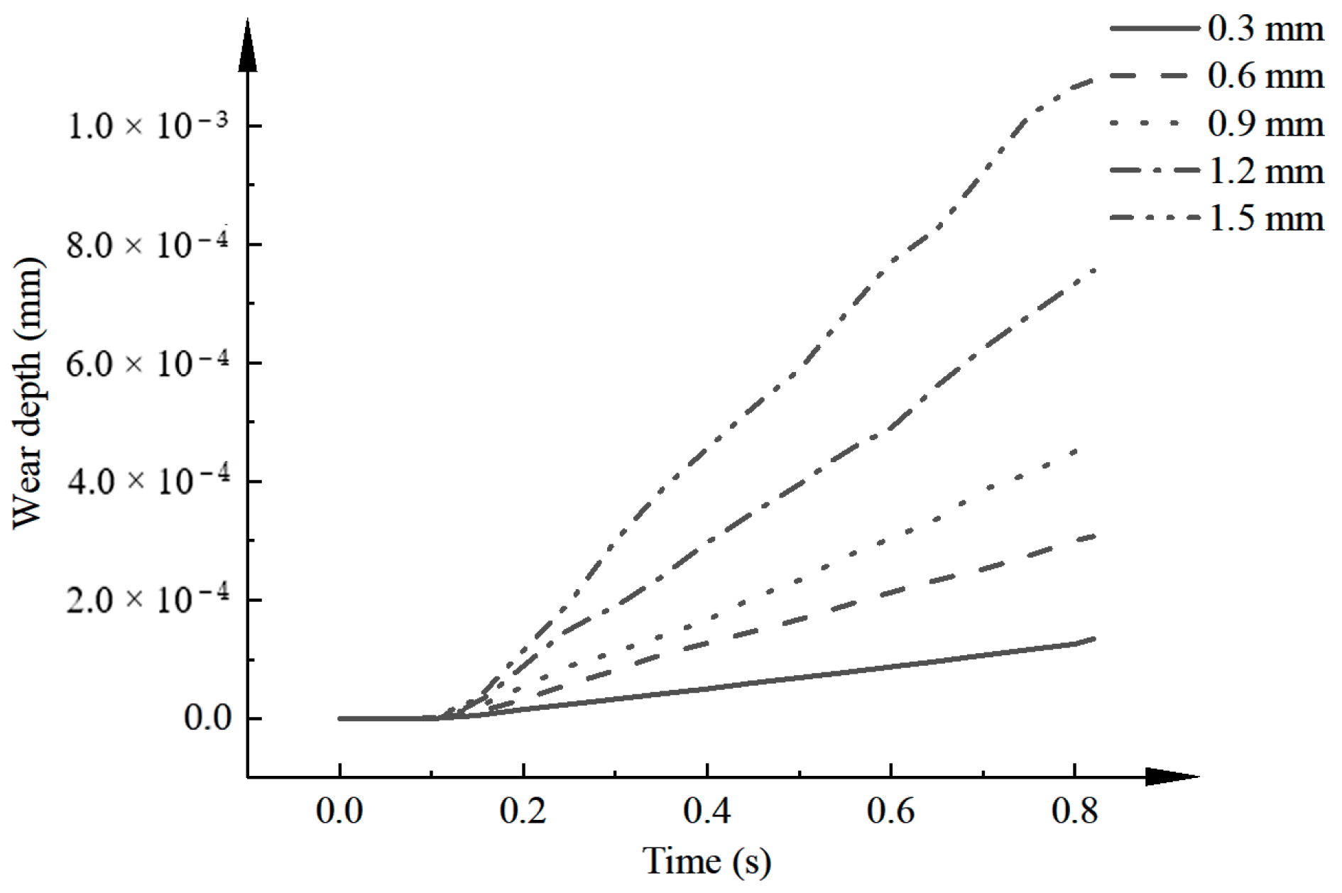
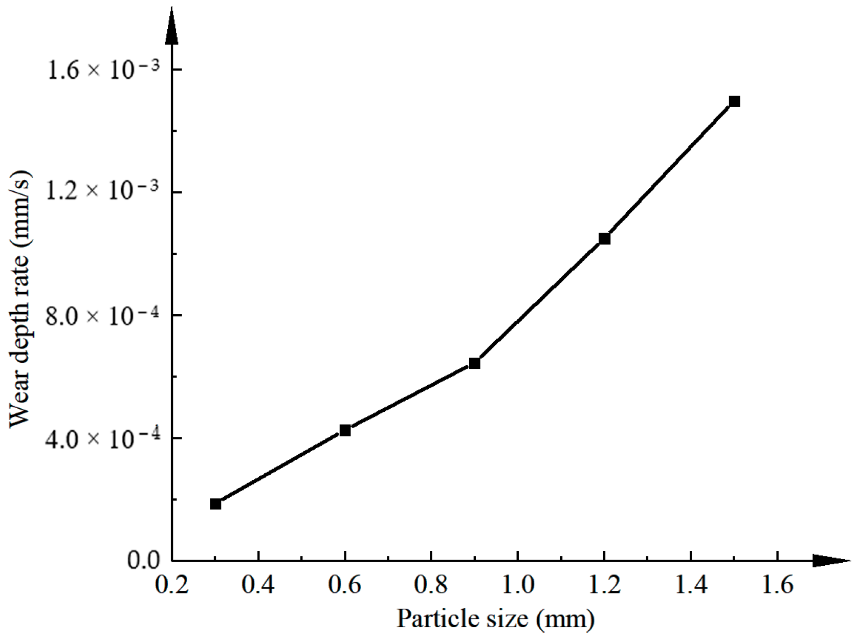
4.2. Effect of Particle Size on Wear Rate

To study the effect of different particle sizes of solid phase particles on the wear of the seal’s surface, the wear depth of the graphite seal surface was calculated at 0.3 mm, 0.6 mm, 0.9 mm, 1.2 mm, and 1.5 mm particle sizes, and the folding line graph of the wear depth distribution at different particle sizes is shown in Figure 18. From Figure 18, the wear depth increases with the increase in the solid phase particle size, and after the wear phenomenon, the wear depth is proportional to the particle size with slope h* = constant. Both the wear depth rate is approximated as a constant value. from Figure 19, the wear depth rate is proportional to the particle size.

4.3. Effect of Working Temperature on Wear Rate

A line graph of the wear depth rate with temperature is shown in Figure 20. From Archard’s abrasive wear equation, the amount of target wear is related to the nature of the target, while the hardness of graphite increases with temperature.
Therefore, the wear depth of graphite also varies with the temperature. As can be seen from Figure 20, when the temperature is less than 200 K, the wear depth decreases rapidly with the increase in temperature. When the temperature is greater than 200 K, the wear depth rises slowly with the increase in temperature. This law is consistent with the graphite hardness variation law with temperature. It indicates that the wear model used in this study is consistent with the actual one.

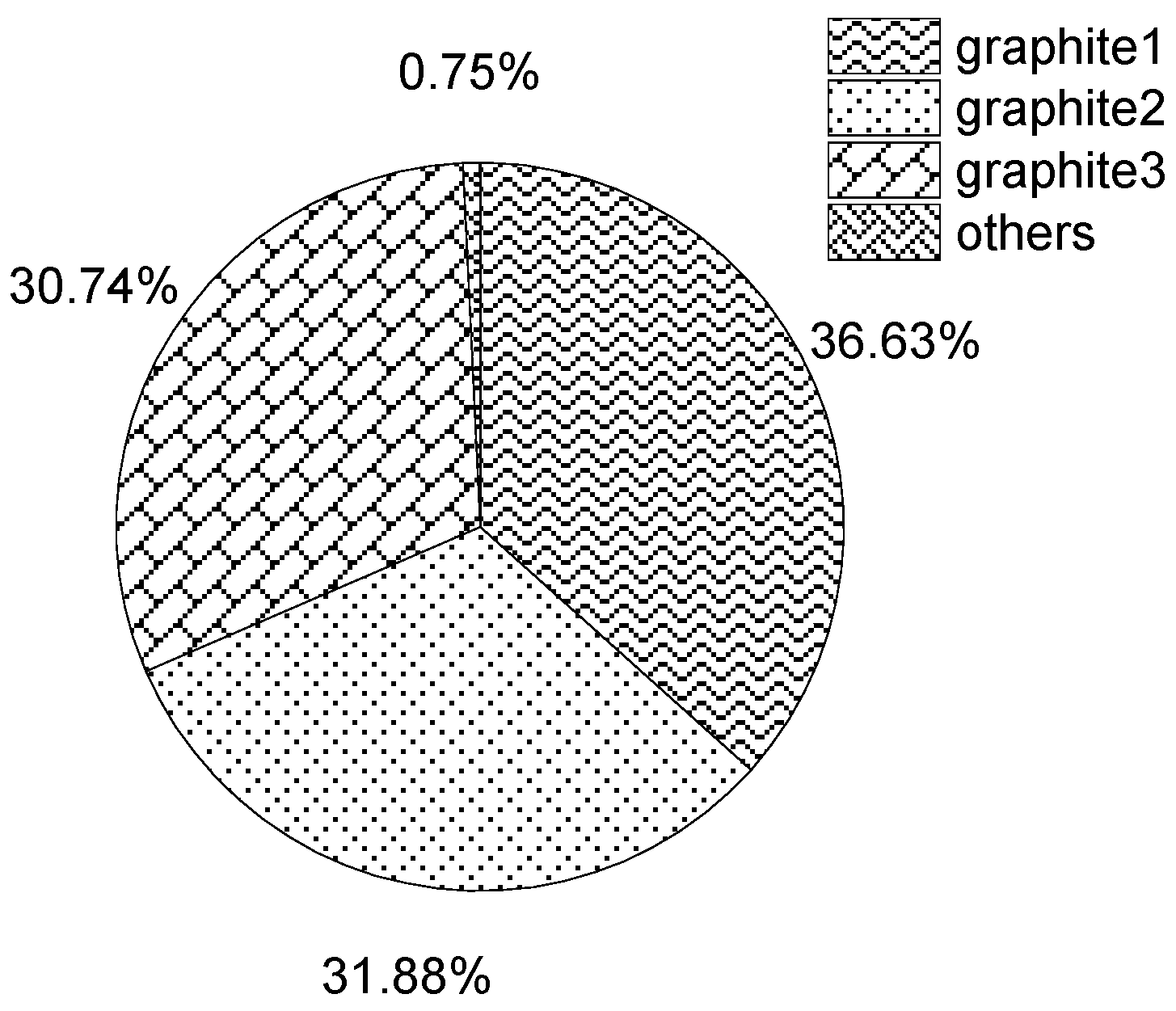
4.4. Effect of Target Material Type on Wear Rate

Wear depth percentage is shown in Figure 21.
From the abrasive wear equation of the Archard model, the amount of wear is related to the nature of the target material, so the depth of wear will vary with the target material. As can be seen from Figure 21, the wear depth of the graphite-sealing surface is much greater than that of the other parts for the same erosive wear time. This is because the graphite-sealing surface is softer than the metal surface, and according to the abrasive wear formula of the Archard model, the wear amount is inversely proportional to the hardness of the target material, so the softer target material has a deeper wear depth than the hard target material.

5. Results

A coupled CFD-DEM method is proposed for the erosion wear problem caused by gas-solid two-phase flow in a triple eccentric butterfly valve. Based on the Eulerian multiphase flow theory and DEM discrete phase theory, as well as the use of the soft sphere model and Archard abrasive wear model, the erosion and wear law are analyzed. There are some meaningful observations in this study, as follows:
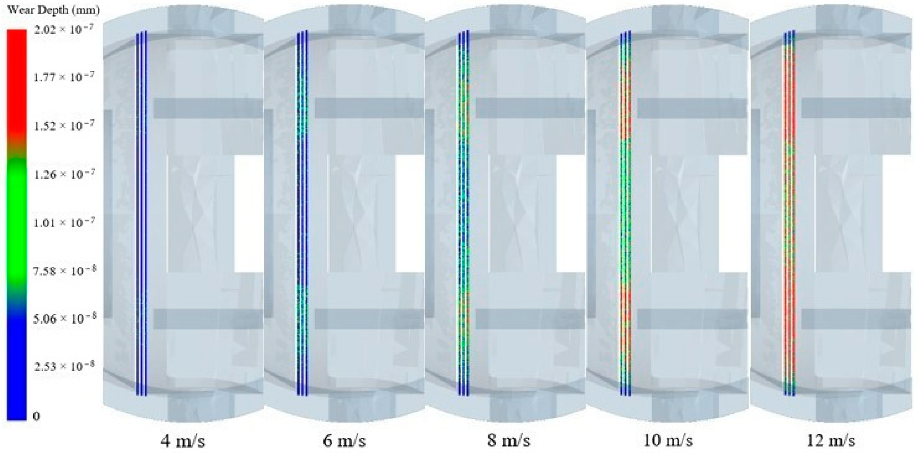
  • At a flow rate of 4 m/s, the maximum wear depth of the seal’s surface is 8.14 × 10⁻⁸ mm, and the simulation time is 1 s, then the maximum wear rate of graphite can be calculated as 2.567 mm/a. A year of erosive wear on the graphite-sealing surface under full open working conditions will result in a wear depth of 2.567 mm;
  • The wear depth in the middle part of the straight side is significantly less than the wear depth on the left and right sides. It indicates the existence of an impact angle that maximizes the wear rate when the cutting action is most significant;
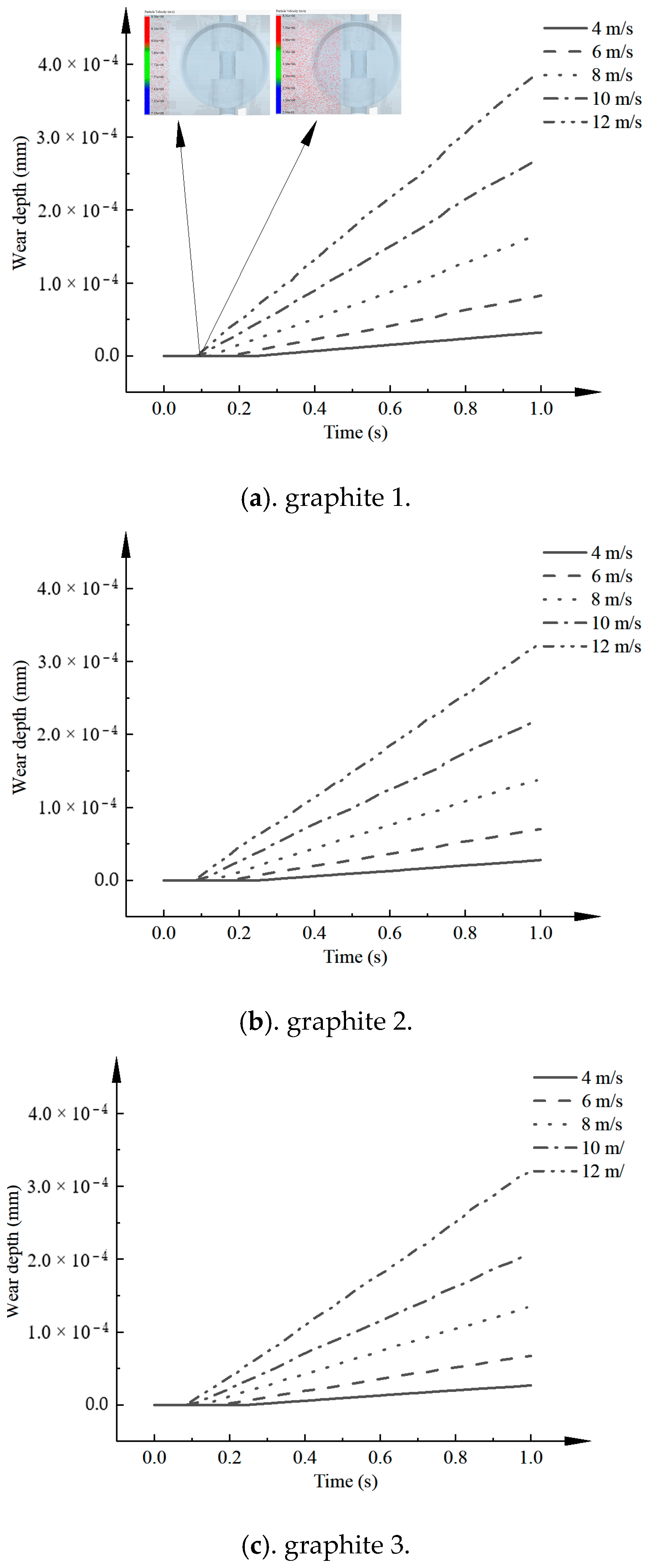
  • The total wear depth of the seal’s surface as a function of time is approximated as a monotonically increasing function, and the wear depth rate is proportional to the flow rate. The wear depth rate is proportional to the particle size. When the temperature is less than 200 K, the wear depth decreases rapidly with the increase in temperature. When the temperature is greater than 200 K, the wear depth increases slowly with the increase in temperature.
Several other benefits can be foreseen using this approach, which are under active investigation. These include the following: The role of the physical force of the solid-phase particles in the kinematic process is fully considered. The kinematic parameters of the solid-phase particles are obtained considering the collisional contact theory.

6. Discussion

According to the above research, we found that the wear depth of a graphite-sealing ring is related to particle motion speed, particle size, medium temperature, and target material type. The research results are consistent with the practice, which provides a reference for the design of high-temperature three-eccentric multi-level butterfly valve. To provide structural reliability verification for butterfly valves used in the field of photothermal power generation. The present study is limited to the numerical simulation without experimental verification under high temperature conditions. The main reason is that the experimental conditions are difficult to achieve. The future research direction is mainly from the high-temperature wear-resistant materials, high-temperature corrosion-resistant materials, and other aspects.
After the graphite seal surface receives erosive wear from debris particles, the seal’s surface is a rough surface made up of many uneven peaks and valleys. At the same time, the roughness of the graphite-sealing surface increases after wear. With the increase in roughness, the possibility of leakage increases and finally leads to seal failure.
In reference [5], the authors use numerical simulations as well as experiments to discuss the erosion mechanism and characteristics of the sealing surface of a ball valve in a gas-solid two-phase flow. The results show that the erosion rate increases with increasing particle velocity and size. The wear depth decreases with increasing hardness. The experimental data are in good agreement with the numerical simulation data. The conclusions in this paper are in good agreement with the results in our paper.

Author Contributions

S.L. designed the research. L.Y. and Y.W. processed the corresponding data. B.Z. wrote the first draft of the manuscript. W.K. and J.Z. helped to organize the manuscript. B.Z. revised and edited the final version. All authors have read and agreed to the published version of the manuscript.

Funding

This research was funded by The Double First-Class Key Program of Gansu Provincial Department of Education, and Gansu Province Science and Technology Program Funding (Grant No. 22CX8GA125).

Data Availability Statement

The data presented in this study are available on request from the corresponding author.

Acknowledgments

I would like to thank my supervisor, Shuxun LI (School of Petrochemical Technology, Lanzhou University of Technology, China), for his guidance through each stage of the process.

Conflicts of Interest

The authors declare no conflict of interest.

References

  1. Alihosseini, M.; Thamsen, P.U. Experimental and numerical investigation of sediment transport in sewers. In Proceedings of the Fluids Engineering Division Summer Meeting, Montreal, QC, Canada, 15–20 July 2018; American Society of Mechanical Engineers: New York, NY, USA, 2018; Volume 51579, p. V003T17A005. [Google Scholar]
  2. Kwak, H.S.; Seong, H.; Brilianto, R.M.; Kim, C. Design of Laminated Seal for Triple Offset Butterfly Valve (350 °C) Used in Combined Cycle Power Plants. Appl. Sci. 2019, 9, 3095. [Google Scholar] [CrossRef] [Green Version]
  3. Wang, B.; Wang, L.; Huang, F. Simulation analyses of dust deposition characteristics on sealing surface of the butterfly valve in blast furnace gas pipelines. In Proceedings of the 2015 7th International Conference on Modelling, Identification and Control (ICMIC), Sousse, Tunisia, 18–20 December 2015; IEEE: New York, NY, USA, 2015; pp. 1–6. [Google Scholar]
  4. Xu, B.; Zhu, Z.; Lin, Z.; Wang, D.; Ma, G. Numerical and experimental re-search on the erosion of solid-liquid two-phase flow in transport butterfly valve based on DEM method. Ind. Lubr. Tribol. 2021, 73, 606–613. [Google Scholar] [CrossRef]
  5. Peng, D.; Dong, S.; Wang, Z.; Wang, D.; Chen, Y.; Zhang, L. Characterization of the Solid Particle Erosion of the Sealing Surface Materials of a Ball Valve. Metals 2021, 11, 263. [Google Scholar] [CrossRef]
  6. Zolfagharnasab, M.H.; Salimi, M.; Zolfagharnasab, H.; Alimoradi, H.; Shams, M.; Aghanajafi, C. A novel numerical investigation of erosion wear over various 90-degree elbow duct sections. Powder Technol. 2021, 380, 1–17. [Google Scholar]
  7. Lin, Z.; Sun, X.; Yu, T.; Zhang, Y.; Li, Y.; Zhu, Z. Gas–solid two-phase flow and erosion calculation of gate valve based on the CFD-DEM model. Powder Technol. 2020, 366, 395–407. [Google Scholar]
  8. Huang, S.; Tang, Z.; Huang, J.; Ou, C.; Hui, Z. Investigation of influencing factors of wear in a sandblasting machine by CFD-DEM coupling. Part. Sci. Technol. 2022, 40, 838–847. [Google Scholar] [CrossRef]
  9. Yao, L.; Liu, Y.; Liu, J.; Xiao, Z.; Xie, K.; Cao, H.; Zhang, H. An optimized CFD-DEM method for particle collision and retention analysis of two-phase flow in a reduced-diameter pipe. Powder Technol. 2022, 405, 117547. [Google Scholar] [CrossRef]
  10. Deng, L.; Hu, Q.; Chen, J.; Kang, Y.; Liu, S. Particle distribution and motion in six-stage centrifugal pump by means of slurry experiment and CFD-DEM simulation. J. Mar. Sci. Eng. 2021, 9, 716. [Google Scholar] [CrossRef]
  11. Kabeel, A.E.; Elkelawy, M.; Mohamad, H.A.; Elbanna, A.M.; Panchal, H.; Suresh, M.; Israr, M. The influences of loading ratios and conveying velocity on gas-solid two-phase flow characteristics: A comprehensive experimental CFD-DEM study. Int. J. Ambient Energy 2022, 43, 2714–2726. [Google Scholar] [CrossRef]
  12. Liang, X.; Liu, X.J.; Xia, D. Numerical investigation of the gas–solid heat transfer characteristics of packed multi-size particles. Int. J. Heat Mass Transf. 2020, 149, 119237. [Google Scholar]
  13. Javaheri, V.; Porter, D.; Kuokkala, V.T. Slurry erosion of steel–Review of tests, mechanisms, and materials. Wear 2018, 408, 248–273. [Google Scholar] [CrossRef]
  14. Liu, M.; Chen, M.; Li, T.; Tang, Y.; Liu, R.; Shao, Y.; Liu, B.; Chang, J. CFD–DEM–CVD multi-physical field coupling model for simulating particle coating process in spout bed. Particuology 2019, 42, 67–78. [Google Scholar] [CrossRef]
  15. Wang, Y.; He, T.; Ding, Q.; Gao, P.; Tao, R.; Zhu, Z. Analysis of Internal Flow and Wear Characteristics of Binary Mixture Particles in Centrifugal Pump Based on CFD-DEM. Processes 2022, 10, 681. [Google Scholar] [CrossRef]
  16. Huang, S.; Huang, J.; Guo, J.; Mo, Y. Study on wear properties of the flow parts in a centrifugal pump based on EDEM–fluent coupling. Processes 2019, 7, 431. [Google Scholar] [CrossRef] [Green Version]
  17. Rajahram, S.S.; Harvey, T.J.; Wood RJ, K. Evaluation of a semi-empirical model in predicting erosion–corrosion. Wear 2009, 267, 1883–1893. [Google Scholar] [CrossRef]
  18. Ji, S.M.; Ge, J.Q.; Tan, D.P. wall contact effects of particle-wall collision process in a two-phase particle fluid. J. Zhejiang Univ.-Sci. A 2017, 18, 958–973. [Google Scholar] [CrossRef]
  19. Zhang, Y.; Men, X.; Wang, S.; Fu, X.; Chen, L. CFD-DEM Study of Pleated Filter Plugging Process Based on Porous Media Model. Machines 2022, 10, 862. [Google Scholar] [CrossRef]
  20. Hu, Z.; Zeng, H.; Ge, Y.; Wang, W.; Wang, J. Simulation and experiment of gas-solid flow in a safflower sorting device based on the CFD-DEM coupling method. Processes 2021, 9, 1239. [Google Scholar] [CrossRef]
  21. Zhou, D.P.; Ma, X.D.; Chen, Y. Simulation Analysis for Erosion Wear of Ω-shaped Pipe Based on CFD-DEM Coupling. China Pet. Mach. 2022, 50, 136–142. (In Chinese) [Google Scholar]
  22. Haiying, Z.; Zhong, H.; Shaoyang, J.; Hongling, D.; Xiaogang, X.; Feng, S. Analysis on Wearing of Bearing for Main Pump in Nuclear Power Plant. Nucl. Power Eng. 2022, 43, 108–111. (In Chinese) [Google Scholar]
  23. Lu, Y.; Liu, S.; Zhang, X.; Jiang, Z.E.D. A Probabilistic Statistical Method for the Determination of Void Morphology with CFD-DEM Approach. Energies 2020, 13, 4041. [Google Scholar] [CrossRef]
Figure 1. Schematic diagram of particle-particle/wall contact process where n is the normal displacement and t is the tangential displacement.
Machines 11 00463 g001
Figure 2. Contact model based on softball model.
Machines 11 00463 g002
Figure 3. Metal-graphite laminate seal structure.
Machines 11 00463 g003
Figure 4. Wear mechanism.
Machines 11 00463 g004
Figure 5. Coupling flow chart.
Machines 11 00463 g005
Figure 6. Schematic diagram of fluid domain, where the velocity of the red particle is greater than the velocity of the green particle, while the velocity of the green particle is greater than the velocity of the blue particle.
Machines 11 00463 g006
Figure 7. Particle modeling.
Machines 11 00463 g007
Figure 8. Map of the division of the outer ring surface of the seal and the distribution of monitoring points.
Machines 11 00463 g008
Figure 9. Schematic diagram of seal ring surface equivalence.
Machines 11 00463 g009
Figure 10. Continuous phase velocity cloud.
Machines 11 00463 g010
Figure 11. Flow field vector diagram where in the figure, the flow velocity in the red area is greater than that in the green area.
Machines 11 00463 g011
Figure 12. Particle distribution cloud map.
Machines 11 00463 g012
Figure 13. The 4 m/s wear depth cloud.
Machines 11 00463 g013
Figure 14. Wear ratio.
Machines 11 00463 g014
Figure 15. Wear cloud of sealing surface at different speeds.
Machines 11 00463 g015
Figure 16. Folding graph of the total wear of the sealing surface at different speeds.
Machines 11 00463 g016
Figure 17. Depth of wear rate versus flow rate line graph.
Machines 11 00463 g017
Figure 18. Total wear of sealing surface at different particle sizes.
Machines 11 00463 g018
Figure 19. Depth of wear rate as a function of particle size.
Machines 11 00463 g019
Figure 20. Depth of wear rate as a function of temperature.
Machines 11 00463 g020
Figure 21. Wear depth percentage.
Machines 11 00463 g021
Table 1. Butterfly valve working conditions parameters.
Design ParametersName/Value
Nominal diameterDN200
Nominal pressurePN16
Media usedBlast furnace gas
Table 2. Parameter table.
Parameter TypeParameter Size
Wear coefficient between particle-graphite0.471 × 10−9
Wear coefficient between particle-metal10−12
Particle density (kg/m3)2650
Graphite density (kg/m3)15.03
Metal density (kg/m3)7800
Particle Poisson’s ratio0.4
Graphite Poisson’s ratio0.206
Metal Poisson’s ratio0.3
Particle shear modulus (MPa)8.8
Graphite shear modulus (kPa)1
Metal shear modulus (MPa)0.1
Recovery coefficient of particle-particle0.27
Recovery coefficient of particle-graphite0.047
Recovery coefficient of particle-metal0.5
Static friction coefficient of particle-particle0.44
Static friction coefficient of particle-graphite0.894
Static friction coefficient of particle-metal0.15
Dynamic friction coefficient of particle-particle0.01
Dynamic friction coefficient of particle-graphite0.001
Dynamic friction coefficient of particle-metal0.01
Disclaimer/Publisher’s Note: The statements, opinions and data contained in all publications are solely those of the individual author(s) and contributor(s) and not of MDPI and/or the editor(s). MDPI and/or the editor(s) disclaim responsibility for any injury to people or property resulting from any ideas, methods, instructions or products referred to in the content.

