Article

Design and Control of an Energy-Efficient Speed Regulating Method for Pump-Controlled Motor System under Negative Loads

1
School of Mechatronics Engineering, Henan University of Science and Technology, Luoyang 471003, China
2
School of Mechanical Engineering, Henan Institute of Technology, Xinxiang 453003, China
3
Center of Machinery Equipment Advanced Manufacturing of Henan Province, Luoyang 471003, China
*
Author to whom correspondence should be addressed.
Machines 2023, 11(4), 437; https://doi.org/10.3390/machines11040437
Submission received: 22 February 2023 / Revised: 22 March 2023 / Accepted: 28 March 2023 / Published: 29 March 2023
(This article belongs to the Section Electrical Machines and Drives)

Abstract

:
Pump-controlled motor hydrostatic system (PCMH) is widely applied for rotary driving in heavy industry and construction machinery due to its high-power density and efficient speed regulation performance. However, the contradiction of the PCMH system between energy saving and speed control appears when it deals with negative loads. To address this contradiction, an energy-efficient speed regulating method based on electro-proportional counterbalance valves (EPCBVs) is designed, along with the corresponding controller. The working principle of the proposed scheme is that under a negative-load operation mode, determined by the supervisory controller according to system states and reference inputs, the speed of the hydraulic motor is controlled by a velocity controller through adjustment of the control signal of the EPCBV, and that the inlet pressure of the hydraulic motor is maintained at a defined low point by a pressure controller through pump displacement control. Comparative experiments between the EPCBV and T-CBV (a PCMH system based on a typical CBV) systems are conducted to verify the superiority of the proposed scheme in energy-efficient speed regulation under negative loads. The results show that, in most of the working conditions, the EPCBV system shows better adaption than the T-CBV system to varying negative loads and maintains higher stability than the T-CBV. Moreover, the speed accuracy of the EPCBV system can be maintained above 95%, which is greater than that of the T-CBV system, varying from 48% to 90%. Furthermore, the maximum power consumption is only about 4 Kw and is far less than that of the T-CBV system, which is about 13.79 Kw. The power-saving ratio changes from 20% to 82%, but it goes beyond 50% in most of the working conditions. The proposed method is easy to implement in practical application and is of great significance to the PCMH system for energy-efficient speed control under negative loads.

1. Introduction

The pump-controlled motor hydrostatic drive system (PCMH) functions as a superior driving method for rotary motion due to its high-power density, easy overload protection, and self-lubrication, making it a super-duper choice for the driving system of the industrial and construction machinery, such as heavy manipulator [1], wind power [2], heavy transportation vehicle [3], PAT oil transmission equipment [4], etc. The PCMH system has smooth and efficient performance of speed regulation [5]. There are many factors that affect its performance, such as the efficiency of pumps and motors [6], dynamic of hydraulic hoses [7], etc. However, the performance will be greatly affected when it comes to dealing with negative-load conditions where the direction of the speed is the same as that of extra loads, such as lowering heavy objects [8], vehicle travelling downhill [9], etc. Under negative loads, on the one hand, the hydraulic pump needs to consume energy to drive the motor to a certain speed. On the other hand, the system also needs to consume enough energy to balance the negative loads of the motor to maintain the stability of the motor speed, which induces extra energy dissipation and causes low energy efficiency. The contradiction of the PCMH system between energy saving and speed regulation is highlighted when it deals with negative loads. What is worse, the hydraulic motor will accelerate by itself with the negative loads if the prime power, such as the internal combustion engine or electric motor, could not provide enough braking forces to the system, causing a severe threat to the safe operation of the system. Thus, an energy efficient counterbalancing speed regulation method is imperative for safe and efficient speed control of the machines under negative loads.
Backpressure control is a common method for dealing with negative loads in hydraulic system. For example, Li proposed a counterbalancing speed control method for the heavy transportation vehicle under long down-slope by adjusting the backpressure of a hydraulic motor connected to the engine [9]. Ho designed a braking speed control method with kinetic energy recovery for a hydraulic motor of the PCMH system by connecting the motor back pressure to a high-pressure accumulator [10]. Ansari conducted an experimental and numerical investigation into using a hydropower plant on oil transmission lines. The hydropower plant replaced the control valves with a gear pump as a turbine to efficiently maintain the backpressure of the oil transmission line and reuse the energy from the oil transmission lines in electric form [4]. Bury investigated the performance of a proportional directional valve controlling the motor starting pressure of a hydrostatic transmission with simulating and experimental methods [11]. The above methods can counterbalance negative loads with pressure control effectively; however, they suffer from the problem of complexity of control and structure.
Another common method for dealing with negative loads is the introduction of counterbalance valves (CBVs). The CBVs have been widely configured in an open-loop hydraulic circuit [12], or pump-controlled cylinder closed-loop circuit [13] to prevent the actuators from uncontrolled movements due to negative loads. Research has been conducted to improve the stability of the system configured with CBVs, such as pilot pressure reconstruction methods [14], external pilot supply method [15], etc. These methods can effectively improve the system stability. However, they cannot guarantee energy efficiency simultaneously. Retelli quantified the energy consumption of the CBVs with different pilot ratios in a systematic manner and showed that there was a high energy-saving potential with a higher pilot ratio, while a higher pilot ratio tends to make the system unstable [16]. It is believed that both stability and energy saving can be improved by separating the pilot pressure from the actuator inlet and adjusting the pilot pressure with an external flow supply [17]. Sciancalepore proposed an energy-efficient speed control method by changing the pilot pressure of the CBV with an external flow source [15]. Jin replaced the CBV with an adjustable orifice to gain extra flexibility for the controller to obtain energy-efficient speed control for systems with negative loads [18]. Thus, the contradiction between stability and energy saving can be addressed by the extra flexibility obtained by independently adjustable pilot pressure. However, to the knowledge of the authors, the studies mentioned above are mainly concerned with the performance of the CBV configured in the open-loop hydraulic circuits, but that used in PCMH systems has not been reported yet.
Inspired by the work of [15,18], this paper proposes an energy-efficient speed regulating system for the PCMH system under negative loads based on an electro-proportional CBV (EPCBV), where the pilot pressure of the CBV is adjusted by a reducing valve powered by an external flow source, thus eliminating the instability problem of CBVs. When the PCMH system works under negative loads, the speed of the motor is adjusted by controlling the input voltage of the EPCBV to obtain better speed control accuracy. In the meanwhile, the inlet pressure of the motor is maintained at a predefined low operation pressure point by adjusting pump displacement control signal to reach the purpose of energy saving. Then, with the coordinate control of the pump and EPCBV, the PCMH system can simultaneously achieve better speed control accuracy and high energy efficiency under negative loads.
A hierarchal controller is designed to ensure the proper work of the proposed system, which is composed of a supervisory controller and a plant controller. The supervisory controller selects the corresponding operation mode from the four-quadrant operation modes defined with the four combinations of the hydraulic motor speed and torque by collecting the reference speed inputs and pressure signals of the system. The plant controller includes a velocity controller (VCOR) for the EPCBV and a pressure controller (PCOR) for the pump. The VCOR adopts feedforward control method combined with feedback control to enhance both the response and accuracy of the system. The EPCBV flow model and the hydraulic motor leakage model are established based on offline experimental mapping to be employed as the feedforward part. A typical PID controller based on speed signal feedback is employed as the feedback part to decrease the control error caused by the modelling error and other system uncertainties. As for the PCOR, a modified integral controller is designed to deal with the flow mismatch problem induced by the model error of the pump and maintain the inlet pressure of the hydraulic motor at the predefined low pressure operation point. The effectiveness of the PCOR is verified by theory analysis.

2. System Formulation

The structure of the PCMH system based on typical configuration with CBV is introduced first, along with the analysis of the cause of contradiction between energy efficiency and stability. Then, the PCMH system based on EPCBV is proposed, and its working principles are presented.

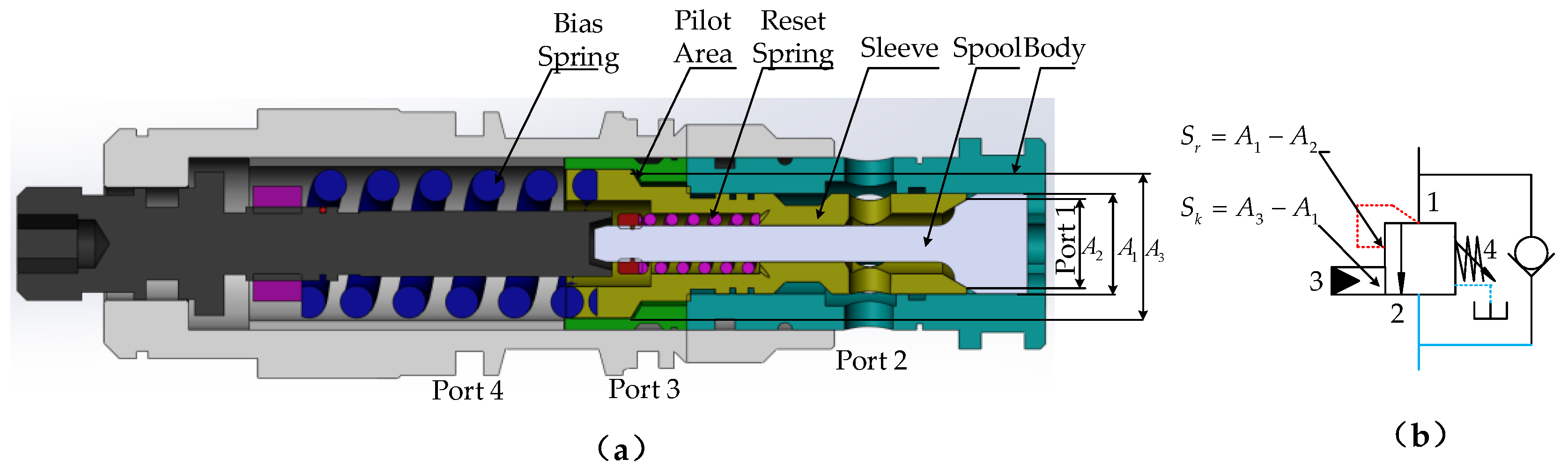
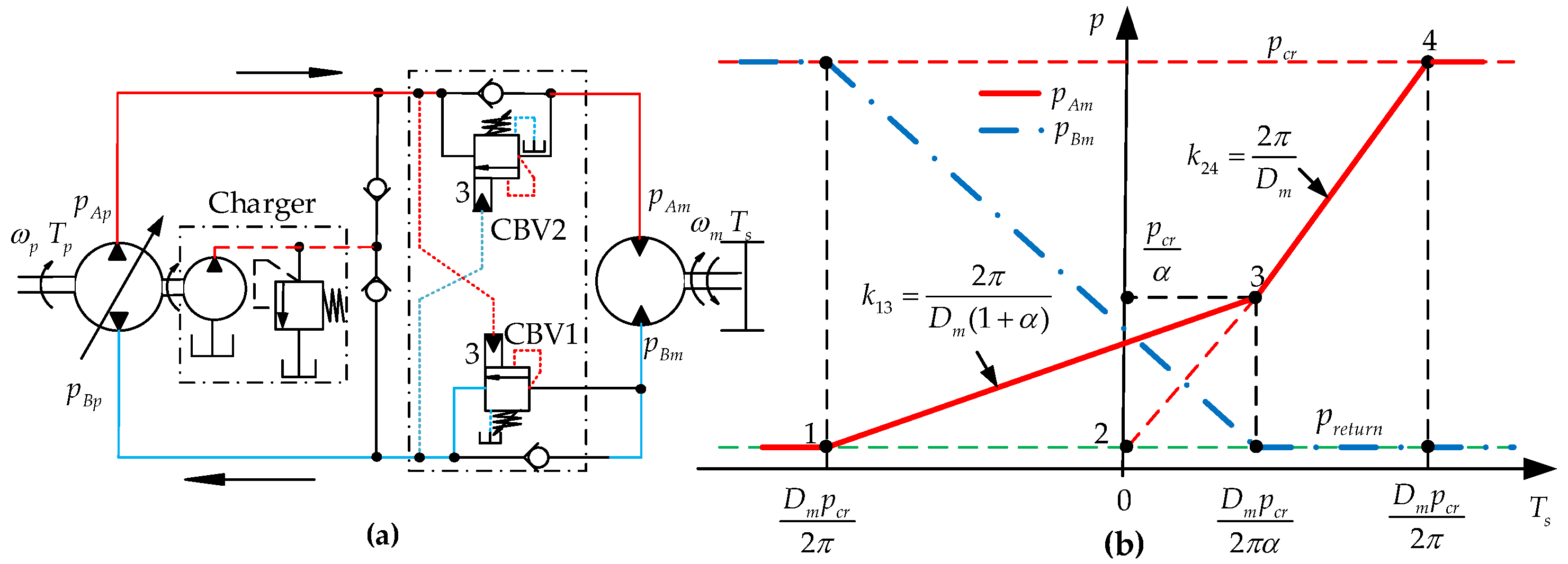
2.1. Typical Configuration with CBV

Although there are kinds of commercially designed architectures of CBV in the market, the one presented in Figure 1a is among the most familiar design. Among all the commercially designed CBVs, there are two common characteristic parameters, the pilot ratio α , and cracking pressure p c r , which are defined as in [15].
α = S k S r p c r = F C B V S r ,
where S r , S k are area differences defined in Figure 1b ( m 2 ), F C B V is the force of the bias spring ( N ), p c r is the cracking pressure of CBV ( Pa ) .
The cracking pressure p c r can be adjusted through the compression of the bias spring in Figure 1a to determine the maximum pressure allowed when the CBV opens.
In Figure 2a, the PCMH system is configured with CBVs in a typical way just as those in the open-loop hydraulic circuits. Since the motor can experience negative loads in both directions, the system is configured with two CBVs, i.e., CBV1 and CBV2. For ease of analysis, the working principle and the influence of CBV on the system are introduced along the direction as the arrow indicates (shown in Figure 2a). Along with the direction of the arrow, the oil pumped out by the pump flows into motor inlet through the check of the CBV2 and at the same time arrives at the port 3 of CBV1. When the motor experiences resistive loads ( T s > 0 ), the pump outlet pressure p A p is greater than pump inlet pressure p B p . Hence, once p A p and motor outlet pressure p B m are high enough to force the orifice of CBV1 to open, the oil of the motor outlet will pass through the throttling orifice of CBV1 and circle back to pump inlet. Then, the motor will rotate with the pressure difference between motor inlet pressure p A m and motor outlet pressure p B m . However, when T s declines to below zero, pump outlet pressure p A p and the pressure of port 3 in CBV1 will also decline, causing the reduction of the throttling orifice area in CBV1 and the increase in motor outlet pressure p B m . Eventually, the rising motor outlet pressure p B m will balance the negative torque T s , prohibiting the motor from self-accelerating.
Although the scheme shown in Figure 2a can address the problem of the motor self-acceleration under negative loads with the help of CBVs, the introduction of CBVs will result in extra energy dissipation. The detailed influence of the CBVs on the system is analyzed as follows. For brevity, the pressure drop of the check valve of the CBVs is neglected, and the equilibrium function of the CBVs can be expressed with Equation (2), which assumes negligible frictional and flow forces, and uniform motion of the motor [19].
F C B V = p c r S r = p A m S k + p B m S r T s = D m ( p A m p B m ) / 2 π ,
where T s is the effective torque of the motor ( N m ) , D m is the displacement of the motor ( m 3 ). Equation (2) can be applied to both resistive loads ( T s > 0 ) and negative loads ( T s < 0 ). Combining with Equation (1), Equation (2) can be rearranged as follows.
p A m = D m p c r + 2 π T s D m ( 1 + α ) p B m = D m p c r 2 π α T s D m ( 1 + α )
The influence of the CBVs on the system is presented in Figure 2b. It can be seen that under negative loads ( T s < 0 ), the CBV introduces a counterpressure to balance the negative torque of the motor, which is very important for uniform speed control of the motor. However, when T s < D m p c r / 2 π α , this counterpressure leads to over-pressurization of the flow supply, making the supply pressure ( p A m ) higher than the ideal value (interval point 1 to point 3), which brings extra energy dissipation. It can also be noted from Equation (3) that a higher pilot ratio α will decrease both p A m and p B m , whereas a higher p c r will increase p A m and p B m . Then, from the view of energy conservation, it will be appropriate to choose a higher pilot ratio α . Unfortunately, a higher α will induce system oscillation and instability, as mentioned in Section 1. To solve the contradictory problem in terms of stability and energy efficiency of the typical configuration of CBV, this work puts forward an alternative solution by the design of EPCBV for the PCMH system to obtain both better speed control accuracy and higher energy efficiency.

2.2. Principle of the Proposed Scheme Based on EPCBV

The schematic of the proposed control system based on electro-proportional CBV (EPCBV) is shown in Figure 3a. Different from the typical configuration of CBV in PCMH systems, this scheme uses two EPCBVs instead of traditional CBVs. The EPCBV adopts an electro-proportional reducing valve (EPRV) supplied by an external power source to adjust the pilot pressure of CBV to make the system more flexible and to obtain control performance and energy saving simultaneously. In order to make the PCMH system work effectively, a controller is designed to control the EPCBV and the pump displacement. The controller collects system working signals such as the inlet and outlet pressure of pump p A p , p B p , the inlet and outlet pressure of motor p A m , p B m , rotational speed of the pump and motor ω p , ω m , and the reference speed and predefined operating pressure of motor ω r e f , p ^ m . Then, the controller determines and sets the output signal u 1 , u 2 , u p according to the operation mode of PCMH system to control EPCBV1, EPCBV2, and pump, respectively. The operation work modes of PCMH can be classified into four quadrants as shown in Figure 3b. In quadrant Ⅱ and Ⅳ operation modes, the system works under resistive condition (positive loads), and the motor works to drive the loads. While, in quadrant Ⅰ and ⅡⅠ operation modes, the system works under negative loads, and the motor will be driven by the loads and works as a pump. Take quadrant Ⅰ and Ⅱ operation modes as examples to illustrate the basic working principle of the proposed scheme.
In quadrant Ⅱ operation mode, as the arrow indicates in Figure 3a, the oil flow pumped out by the pump is squeezed through the check valve of EPCBV2 and into the motor inlet. The outflow of motor is pushed through the orifice of the EPCBV1 and eventually circles back to the pump inlet. Thus, the motor will rotate under the pressure difference to drive the loads in a specific direction. The motor speed can be adjusted by pump displacement control signal u p , which depends on the reference input speed ω r e f , and can be formulated as u p = f ( ω r e f ) . Hence, it is necessary for EPCBV1 to be fully opened to minimize the pressure drop of EPCBV1 and obtain higher energy efficiency. Then, the controller will set u 1 to its maximum value u 1 max . As for EPCBV2, its function is not activated and set as u 2 = 0 .
In quadrant Ⅰ operation mode, the system works under negative loads, the motor is driven by extra loads and tends to run out of control of the pump displacement signal u p , making the motor inclined to self-accelerate. However, the controller will force the motor to follow ω r e f by adjusting voltage input u 1 of EPCBV1. The control signal u 1 depends on ω r e f , p B m and p A m , and can be calculated as u 1 = f ( ω r e f , p B m , p B p ) . In the meantime, the inlet pressure of motor is maintained at the predefined low operation point p ^ A m through the adjustment of pump displacement control signal u p to achieve the purpose of energy saving. The pump displacement signal u p is connected with ω r e f , p A m and p ^ A m , and can be expressed as u p = f ( ω r e f , p ^ A m , p A m ) . As for quadrant ⅡⅠ and Ⅳ operation modes, the working process are the same as quadrant Ⅰ and Ⅱ operation modes, and the formulations of the control signals are shown in Figure 3b.

3. System Modelling

Mathematical models of the PCMH system based on an EPCBV are established to analyze in detail the working process of the proposed control scheme for the system under negative loads.

3.1. Model of PCMH System

The torch balance Equation [20] of the motor is expressed as follows.
J m ω ˙ m + B m ω m + Δ p m D m / 2 π = T s ,
where J m is the equivalent moment inertial ( Kg m 2 ) , ω m is the angular velocity of motor ( rad / s ) , B m is damping coefficient ( N s m / rad ) , Δ p m is the pressure difference between motor inlet and outlet ( Pa ) , denoted as Δ p m = p A m p B m .
Under negative loads, the motor works as a pump, and the flow q ( m 3 / s ) out of the motor can be calculated from Equation (5).
q = ω m D m ( C t Δ p m + V 0 Δ p ˙ m / β e ) ,
where C t is leakage coefficient ( m 3 / s Pa ) , and C t Δ p m is referred to as flow leakage loss ( m 3 / s ) , V o is the volume of the flow path ( m 3 ) , β e is the bulk modulus of oil ( Pa ) , and V 0 Δ p ˙ m / β e is referred to as flow compression loss ( m 3 / s ) .
When the flow q passes through the orifice of the CBV, according to the structure of the CBV shown in Figure 1a, the static force balance equation of the spool can be approximately calculated as Equation (6), referring to [15], in which friction and flow forces are negligible.
p 3 S k + p 1 S r = k s ( x 0 + x ) = F C B V + k s x ,
where k s , x 0 are the stiffness ( N / m ) and preset compression of the bias spring ( m ) , respectively, x is the spool displacement ( m ) , p 1 , p 3 are inlet and pilot pressure of CBV ( Pa ) , respectively.
Neglecting leakage of the CBV, the flow passing through the orifice of the CBV will be equal to the flow out of the motor, and we have
q = C d W x Δ p 0 ,
where C d is the flow coefficient ( m 2 / s Pa ) , W is the area gradient of the orifice ( m ) , Δ p 0 is the pressure difference of the orifice ( Pa ) , denoted as p 1 p 2 .
The pilot pressure p 3 ( Pa ) is adjusted by the electro-proportional reducing valve (EPRV), and the relationship between its control pressure and voltage input u ( V ) is simplified as follows [21].
p 3 = k p u u ,
where k p u is pressure gain coefficient of EPRV ( Pa / V ) .
Combining Equations (6)–(8), the flow model of EPCBV can be obtained
q = C d W ( k p u u S k p 1 S r F C B V ) k s p 1 p 2 = f ( u , p 1 , p 2 )
Although parameters S k , S r , W , k s can be determined according to the manufacture’s design, and F C B V can be adjusted according to specific application, it is still challenging to obtain the exact expression of Equation (9) due to modelling error, parameter uncertainties, and valve dead-band. To solve this problem, this paper establishes the flow model of the EPCBV based on flow mapping through testing experiments.

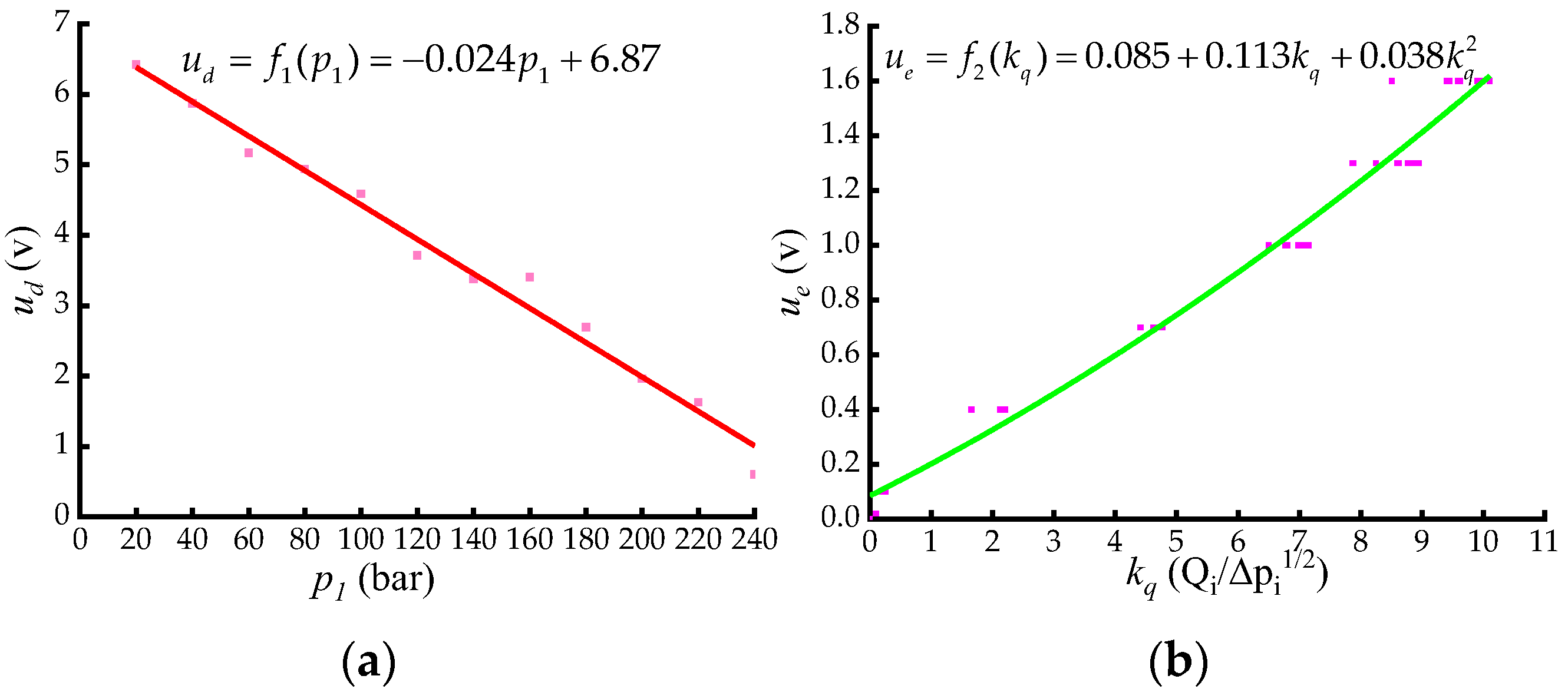
3.2. Flow Model of EPCBV

Mapping-based control methods have been widely used in independent metering system to describe the flow characteristic of the proportional flow valve to improve the control accuracy [22,23]. The basic idea of flow mapping can also be applied to identify the formula of flow model of EPCBV shown in Equation (9). To ensure the quality of the experimental data for the curve fitting, the pressure p 1 , p 2 , voltage input u , and flow rate q of the EPCBV are collected under different conditions to fully cover the working range of the system. According to Equations (6) and (8), it is noted that for a given F C B V , the spool displacement x is linked to both the inlet pressure p 1 and voltage input u . Then, to establish a one-to-one corresponding relationship between x and u , we suppose that p 1 causes the dead-band of the valve. Thus, the voltage input u can be divided into two parts.
u = u e + u d ,
where u e is the effective control signal ( V ) , u d is the dead-band signal ( V ) .
It can be inferred from Equation (6) that the relationship between u d and p 1 is approximately linear, and it can be expressed as Equation (11), which is identified by linear curve fitting method based on least square.
u d = f 1 ( p 1 ) = a p 1 + b
where a , b are fitting coefficients, and can be obtained by the following steps.
Step 1. Record the voltage input u i at the instant when the flow of CBV just starts to go beyond zero under different inlet pressure p 1 i and assume u i as dead-band signal u d i . Then a series of data ( p 11 , u d 1 ) , ( p 12 , u d 2 ) ( p 1 n , u d n ) can be obtained.
Step 2. Based on the obtained data sets, the linear expression f 1 can be identified with linear fitting method. The result is shown in Figure 4a.
After setting the effective control signal u e of the EPCBV fixed at different pressures and regulating the flow rate q through it, a set of points ( u e i , q i j , Δ p i j ) can be acquired. Define the flow gain k q = q / Δ p and rearrange the above obtained data sets, then data sets ( u e i , k q i ) are obtained. The expression f 2 between u e and k q can be formulated with polynomial fitting method, as shown in Equation (12).
u e = f 2 ( k q ) = i = 0 n β i k q i
The identified result of f 2 is shown in Figure 4b. Combining Equations (10) and (11) with Equations (9) and (12), the flow model of the EPCBV can be formulated as.
u = f 1 ( p 1 ) + f 2 ( k q ) = f 1 ( q , p 1 , p 2 )
With the established flow model of the EPCBV, as for given values of q , p 1 , p 2 , the voltage input u can be determined with Equation (13).

3.3. Motor Leakage Estimator (LEOR)

Under negative loads, the motor works as a pump and forces the oil through EPCBV then eventually to the pump. According to Equation (5), the speed of motor can be adjusted through EPCBV by controlling the voltage input u . However, this open-loop control accuracy will be affected by motor leakage loss and oil compression loss, which must be compensated for accuracy improvement. Considering the fact that the compression flow loss is relatively much smaller than leakage flow loss under pressure blow 300 bar [24]. Considering the load conditions of the motor, this work neglects the compression flow loss and only establishes the leakage flow model to compensate the flow loss of the motor. In terms of the leakage of pump or motor, there are many influencing factors, such as displacement, oil temperature, rotating speed, pressure, and so on [20,24]. What is more, there exiting nonlinear relationship between pressure and leakage [25]. Many researchers have adopted pump flow compensation methods based on flow mapping to address the nonlinearity of the pump flow [25,26,27], which is very inspiring for our research work. Then a motor flow mapping method based on response surface methodology is adopted to establish the motor leakage model. To improve the accuracy of the motor leakage model, the model is separated into two parts, the low-speed region and the high-speed region, which is distinguished by a predefined speed margin.
The motor leakage response surface is designed based on Design-Expert software. The specific application of the software can be referred to the literature [28]. Let the motor work under the combinations of different speeds and different pressures specified by the software, rich data sets can be obtained, including pressure difference Δ p , leakage flow q L and motor speed ω m . Then, the motor estimation model can be identified with the software. The identification results are expressed as Equation (14), and the fitting curves are shown in Figure 5.
q L = 1.59 + 6.15 × 10 3 Δ p 1.06 × 10 3 ω m + 3.13 × 10 5 ω m Δ p .   ω m < 1000   r / min q L = 16.7 + 0.12 Δ p 0.044 ω m 1.3 × 10 4 Δ p ω m + 6.05 × 10 5 Δ p 2 + 3.68 × 10 5 ω m 2 + 1.23 × 10 7 Δ p 2 ω m + 4.22 × 10 8 Δ p ω m 2 8.35 × 10 7 Δ p 3 9.88 × 10 9 ω m 3 .   ω m > = 1000   r / min

4. Controller Design

The concept of pump-valve coordinate control has been a hot research topic in recent years for an electro-hydraulic independent metering system to simultaneously achieve high control accuracy and high energy efficiency [22,29,30]. These references present numerous experiences and techniques for the coordinate controller design, which brings great help for the controller design of the proposed control system. Combined with the characteristics and requirements of the PCMH system based on an EPCBV, a two-level controller is introduced. The upper level is the supervisory controller, which is designed to select efficient operating modes according to the system states and reference inputs, and to control the transitions between the two modes.
The lower-level controller comprises two parts, a velocity controller (VCOR) and a pressure controller (PCOR). Velocity controller (VCOR) is aimed to regulate the motor speed through EPCBV control signal u 1 , u 2 to force the motor to follow the reference speed ω r e f . The pressure controller (PCOR) is designed to maintain the inlet pressure of the motor at the defined low operation pressure p ^ A m by control pump displacement u p to save energy. The overall control scheme is shown in Figure 6a.

4.1. Supervisory Controller

The supervisory controller selects the operation mode based on the four-quadrant operation modes, as shown in Figure 5, which are defined based on the four combinations of the directions of static torque and speed of the motor. The negative load is defined as the case that the direction of the torque and speed of motor are the same, otherwise, it is called resistive load. The direction of the motor is determined by the reference speed input ω r e f instead of motor actual speed ω m , and the torque of the motor can be calculated as T s = D m ( p A m p B m ) . After above definitions, the controller can select the operation mode automatically. Since this work only focuses on the motor speed control under negative loads, the speed control methods for resistive loads are not in our analysis scope.

4.2. Velocity Controller (VCOR)

The velocity controller, which is composed of the feedforward part and the feedback part, is designed to guarantee both fast response and stability of the PCMH system. The control scheme is shown in Figure 6b.

4.2.1. Feedforward Control

The feedforward control signal u f is calculated based on the flow model of EPCBV. According to the collected pressure signal p B m , p B p and the desired flow q d , the control signal u f is determined with Equation (13) and can be expressed as.
u f = f 1 ( q d , p 1 , p 2 ) ,
where the desired flow q d = D m ω r e f q ^ L .

4.2.2. Feedback Control

For the easy implementation of the control system in practical application, a typical PID controller based on motor speed feedback signal is introduced to compensate the speed error introduced by modelling error, oil compression, extra disturbance, and system uncertainties. The feedback control signal can be formulated as [31].
u b = K p e ω + K I t 0 t e ω d t + K D d e ω d t ,
where e ω is speed error, denoted as e ω = ω r e f ω m .

4.3. Pressure Control (PCOR)

The pump supplies oil to the inlet of the motor according to the desired flow q r e f through pump displacement adjustment. However, the assumption that the pump displacement control signal u p is just determined in proportion to the desired calculated supply flow q r e f will introduce flow mismatch between the actual flow and the desired flow caused by leakage, compression, and parameter uncertainties of the pump. The flow mismatch will produce over-pressurization or cavitation to the inlet flow of the motor, leading to extra energy consumption or system instability [32]. Then, a pressure controller is designed to maintain the inlet pressure at a desired lower operation point to reach the goal of energy conservation and stability. Since the speed of the motor can be controlled by velocity controller and the EPCBV responses faster than the pump, the pressure controller can be designed separately to decrease the influence of the inlet pressure dynamic on motor speed dynamic to some extent.
Neglecting the pump leakage, the flow rate q p of pump is defined as Equation (17).
q p = f p ( u p ) ,
where u p is the displacement control signal.
The desired operating point of motor inlet pressure p A m is denoted as p ^ A m , and the error is defined as p δ = p A m p ^ A m . Neglecting the leakage of CBV and the motor, the derivative of p δ can be described as follows.
p ˙ δ = p ˙ A m = β e V 0 ( q p D m ω m )
A variable u p t is defined to be subjected to
q p t = f p ( u p t ) = D m ω r e f ,
where u p t is pump ideal control signal under reference input ω r e f .
The differential of Equation (19) is formulated as follows.
q ˙ p t = f p ( u p t ) u ˙ p t = k p u ˙ p t = D m ω ˙ r e f ,
where k p = f p u p u p = u p t is flow gradient of the pump and can be estimated as k ^ p = ω p D p max . Herein, ω p , D p max are the rotary speed and maximum displacement of the pump, respectively.
The control law of PCOR is designed as follows.
γ ˙ p = p δ D m k ^ p k γ ω ˙ r e f u p = k t p δ k γ γ p + D m k ^ p ω δ ,
where k t , k γ are the control parameters, k t p δ and k γ γ p are the pump controlling components induced by pressure error p δ and reference input ω r e f , respectively, ω δ is the motor speed error and can be denoted as ω δ = ω m ω r e f , γ p is the actual pump control gradient, which satisfies
γ p δ = γ p γ p t k γ γ p t = u p t ,
where γ p t is ideal pump control gradient under reference input ω r e f .
According to Equations (20)–(22), the dynamic of γ p δ can be derived as follows.
γ ˙ p δ = p δ + D m k t k ^ p ( k ^ p k p 1 ) ω ˙ r e f
Substituting Equations (17)–(18) and into Equation (21), the dynamic of p δ is obtained as follows.
p ˙ δ = β e V o [ f p ( k t p δ k γ γ p δ k γ γ p t + D m k ^ p ω δ ) D m ( ω δ + ω r e f ) ] β e V o [ k p ( k t p δ k γ γ p δ + D m k ^ p ω δ ) D m ω δ ] = k t k p β e V o p δ k γ k p β e V o γ p δ + β e D m V o ( k p k ^ p 1 ) ω δ
Combining Equation (23) with Equation (24), the dynamic of the controller is rearranged as follows.
γ ˙ p δ p ˙ δ = 0 1 k γ k p β e V o k t k p β e V o γ p δ p δ + D m k t k ^ p ( k ^ p k p 1 ) ω ˙ r e f β e D m V o ( k p k ^ p 1 ) ω δ
Since the parameter D m is a fixed value, and the system parameters β e , V 0 are approximately constant values in practical application, the real part of the eigenvalue of the main matrix of Equation (25) can be negative to guarantee the stability of the system by setting the controller parameters k t , k γ to proper values. Then, the error of the control pressure will be bounded by ω ˙ r e f and the error of motor speed ω δ . If both ω ˙ r e f and ω δ converge to a small value, the inlet pressure error will converge to a small value too, which maintains the inlet pressure within a specific range of the desired operating pressure p ^ A m .

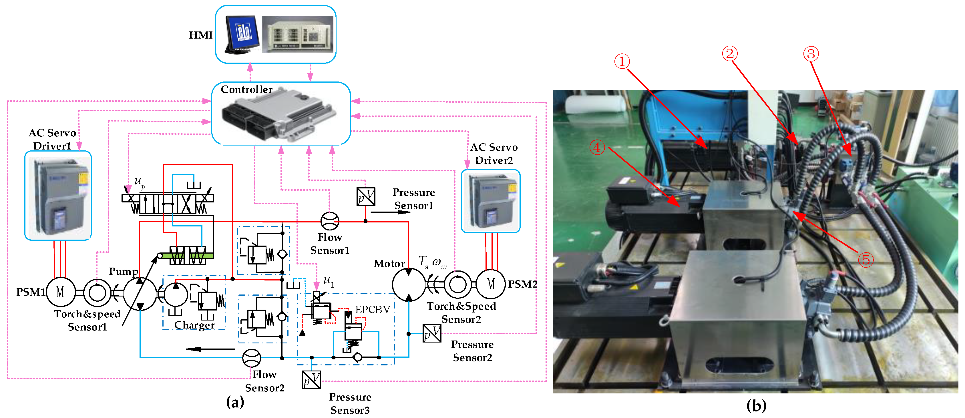
5. Experimental Investigation

A pump-controlled motor test bench is built to validate the superiority in control accuracy and energy saving of the proposed PCMH system based on an EPCBV. As a comparison, the performance of the PCMH system based on a typical configuration of a CBV is also researched and used as a reference. Then, for brevity of analysis, a T-CBV is indicated as the PCMH system based on a typical CBV, and an EPCBV is used to represent the PCMH system based on an EPCBV.

5.1. Test Bench Setup

The schematic and photograph of the test bench are shown in Figure 7a and Figure 7b, respectively. Although the test bench is designed for the EPCBV system, it is convenient to obtain the T-CBV system by just replacing the EPCBV with a typical CBV. For the test bench, the hydraulic pump and hydraulic motor are each connected to an interior permanent magnet servo motor (IPM), named IPM1 and IPM2, respectively. The IPM1 controlled by AC Servo Driver1 drives the pump to supply flow oil for the PCMH system, while IPM2 controlled by AC Servo Driver2 functions as a load simulator to construct loads to the hydraulic motor. To simulate the working conditions of the PCMH system under negative loads, both the IPM1 and IPM2 need to be operated under “torque mode”, where the torque is the main control variable, and the speed is a dependent variable with the maximum allowable value. IPM2 produces a desired negative torque to drive the hydraulic motor to work as a pump. Meanwhile, IPM1 produces a predefined reference torque to the pump to counter the negative torque. The detailed parameters of the main components of the PCMH system are shown in Table 1.

5.2. Experimental Programs

Based on the test bench shown in Figure 7, comparison experiments between T-CBV and EPCBV are conducted under different working conditions of the PCMH system to make a comprehensive evaluation of the two systems.

5.2.1. T-CBV System

In this part, the performance of the T-CBV system is researched, which can be conveniently implemented by replacing the EPCBV with a typical CBV. The characteristic of the typical CBV is shown in Table 1. With the established T-CBV system, the influence of CBV on the PCMH system can be studied. To make a comprehensive analysis, different negative torques T s (from −5 N·m to −40 N·m) are applied to the motor by IPM2 with different reference inputs ω r e f (from 300   r / min to 1500   r / min ).

5.2.2. EPCBV System

With the EPCBV test bench schematic shown in Figure 7a, the performance of the proposed EPCBV system can be researched. The working conditions for the EPCBV system are set the same as those in T-CBV, and the expected operation pressure point of the motor inlet is set as p ^ A m = 25   bar . In order to ensure the performance of the EPCBV system, the control parameters of the controller need to be properly determined. Based on theoretical analysis results and trial-and-error methods, the main parameters of the controller are determined, which are shown in Table 2.

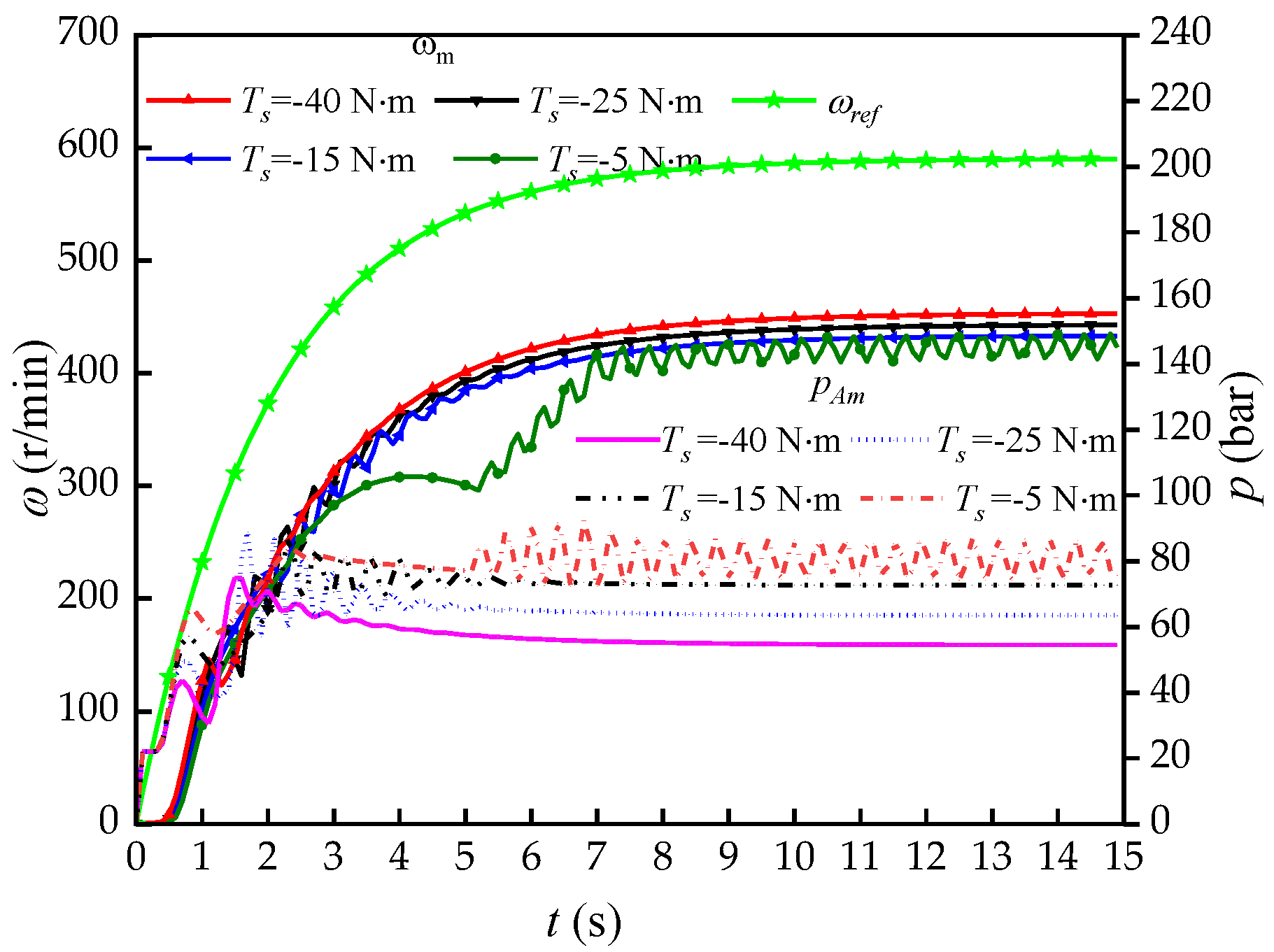
5.3. Experimental Results Analysis

Based on above experiment results, comparative analysis in terms of stability, control accuracy, and power saving is conducted to comprehensively validate the superiority of the proposed EPCBV system.

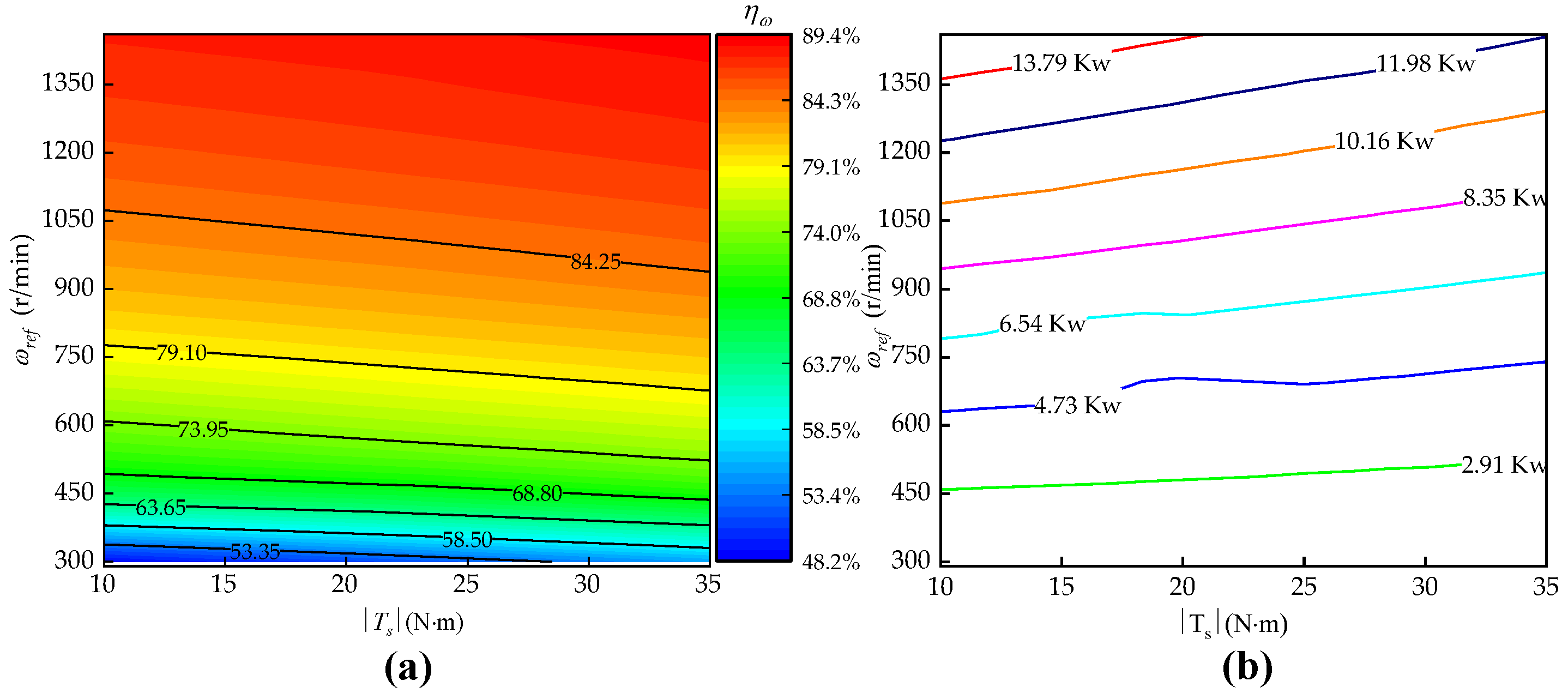
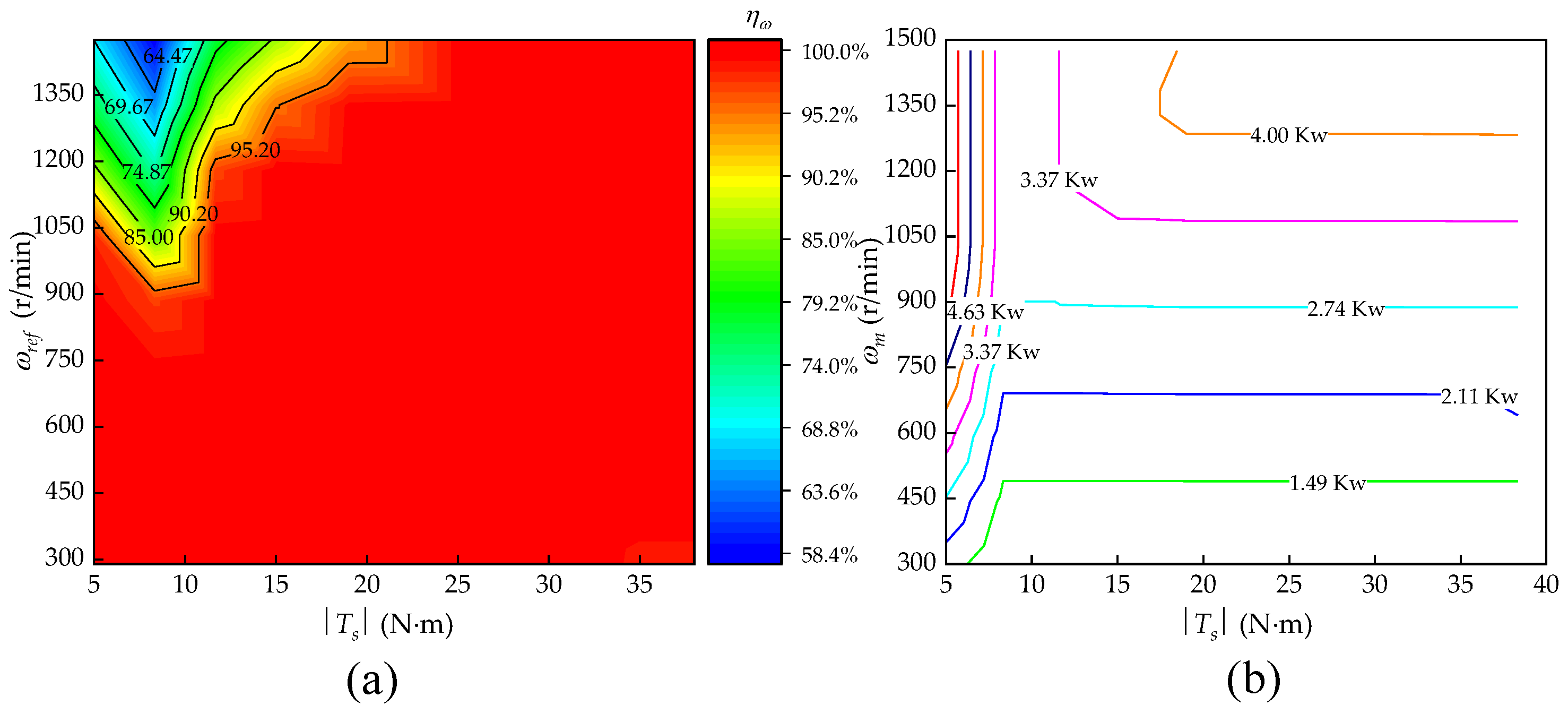
5.3.1. Stability Analysis

Figure 8 shows the responses of the T-CBV system under different negative torques with reference input ω ref = 590   r / min and pilot ratio α = 3 , including motor speed and motor inlet pressure. It can be noted that the stability of the T-CBV system can be guaranteed in most working conditions. However, when the load torque decreases to T s = 5   N m , oscillation appears, and the system becomes unstable, which indicates the poor adaptation of the T-CBV system to the varying negative loads.
As a contrast, Figure 9 also demonstrates the responses of the EPCBV system under the same load torques and reference speed inputs as those set in T-CBV system. It is obvious that the motor speeds converge to steady values, and the motor inlet pressure is maintained around the expected pressure operation point p ^ A m = 25   bar with just small fluctuations, which agrees with the conclusion that the pressure error is bounded, drawn in theoretical analysis of the pressure controller design. Furthermore, the pressure error is relatively small when compared to the working pressure range of the PCMH system and can be well accepted in practical application.
From the above stability analysis, it is concluded that the stability and the adaptation to varying negative loads of the EPCBV system are both higher than those of T-CBV, which validates the advantage of the proposed system in the performance of stability.

5.3.2. Accuracy Analysis

An accuracy parameter, denoted as η ω = ω m / ω r e f , is employed to characterize the performance of the system in speed control accuracy. Figure 10a shows the map of speed control accuracy obtained in the T-CBV system for different reference speed inputs and different negative torques. It can be seen that the self-acceleration of motor is avoided, and the motor speed can be controlled to follow the reference inputs. However, the control accuracy η ω varies greatly, from 48% to 90%, depending on the working conditions. The η ω shows greater dependency on the reference speed input ω r e f than negative torques T s , and it increases quickly with the increase of ω r e f , while it slightly decreases with the increase of T s . The control error and its dependency on the working conditions can be attributed to the leakage of the pump and motor.
Figure 11a shows the accuracy map of the EPCBV system obtained in the same conditions as those set in T-CBV system. It is obvious that the speed control accuracy η ω can be above 95% in most of the working conditions, which shows the excellent performance in speed control accuracy of the proposed EPCBV system. However, in the region where T s < 15   N m and ω r e f > 900   r / min , the control accuracy η ω decreases to around 64%. The reason for the control accuracy decrease can be explained by the flow saturation of the EPCBV under lower T s , which is the drawback of the proposed the system and need to be addressed in future research.
Although the EPCBV system shows some decrease of control accuracy in some small regions, it still demonstrates higher speed control accuracy than T-CBV, which verifies the effectiveness of the VCOR in the proposed EPCBV system.

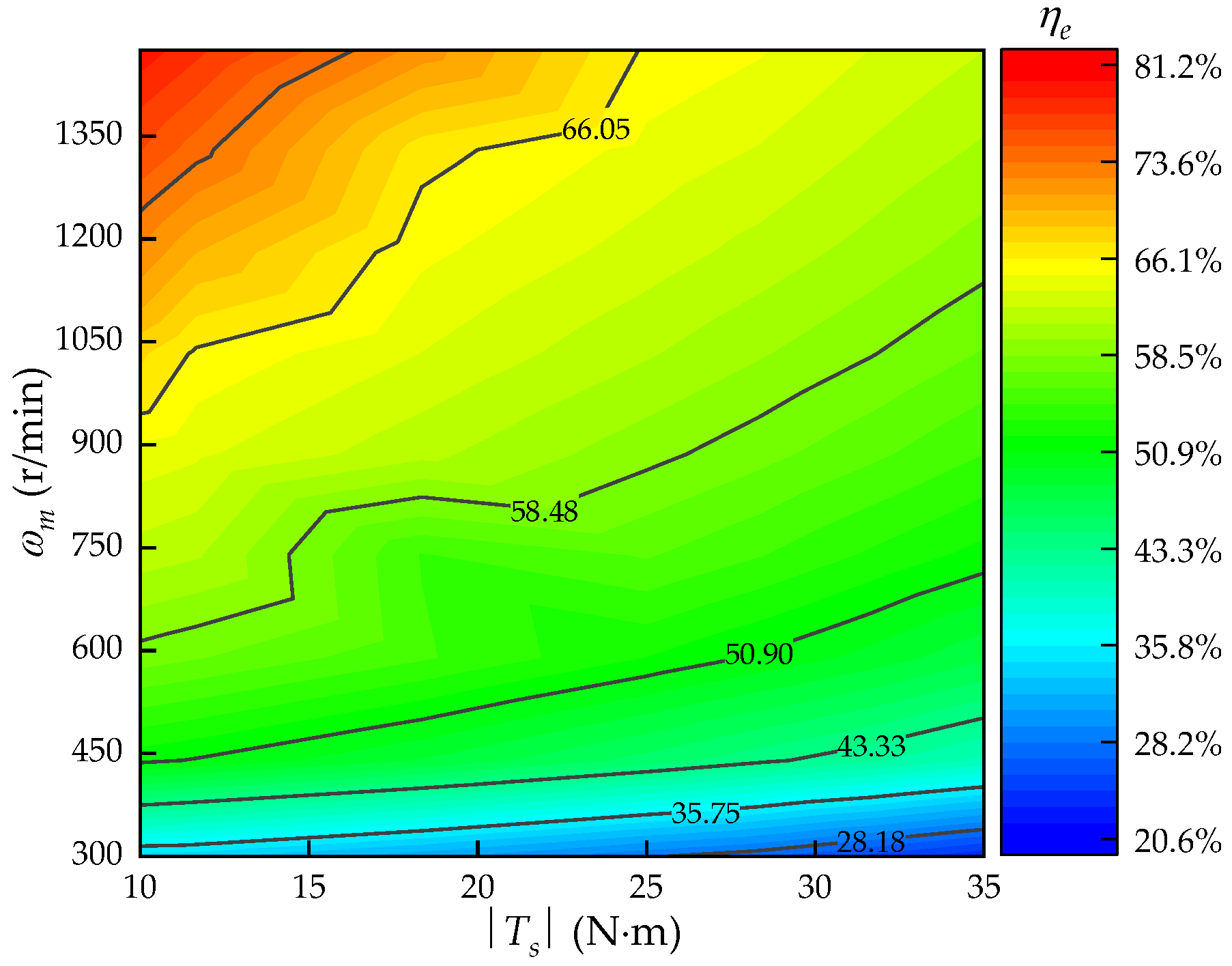
5.3.3. Energy Consumption Analysis

The parameter of power consumption, which is denoted as P = p q , is introduced to describe the energy consumption of the system, where p is the motor inlet pressure, and q represents the flow of motor inlet. Figure 10b shows the power consumption map obtained in the T-CBV system under different reference inputs ω r e f and different negative torques T s . It can be seen that the power consumption of the T-CBV system mainly depends on ω r e f , it increases quickly with the increase of ω r e f , and its maximum can be up to 13.79 Kw. While the power consumption shows a small increase with the decrease of T s , which means that the smaller of T s , the more energy consumed. For comparison, Figure 11b shows the power consumption map obtained in the EPCBV system under the same conditions as those set in the T-CBV system. It is obvious that the power consumption only depends on reference input ω r e f and shows independence from T s in most of the working regions, and its maximum is only up to 4 Kw. Although in the regions where the flow saturation of the EPCBV occurs, the power consumption of the EPCBV system shows dependency on T s and increases with the decrease of T s , its maximum power consumption only reaches 4.63 Kw, which is only slightly greater than that of most other regions.
A power-saving ratio, defined as η e = P T C B V P E P C B V / P T C B V , is employed to compare the power consumption of the T-CBV system and EPCBV system, where P T C B V represents the power consumption of the T-CBV system, and P E P C B V represents that of the EPCBV system. Figure 12 demonstrates the power saving map of the two systems, which shows that the power-saving ratio η e varies from 20% to 82%, depending on the working conditions of the PCMH system. Furthermore, the power-saving ratio goes beyond 50% in most of the operating range of the system, which shows the higher energy saving potential of the proposed system.

6. Discussions

The experimental results show that both the EPCBV system and T-CBV system can effectively prevent the motor from self-accelerating and maintain the proper control of the motor speed. However, compared with the T-CBV system, the EPCBV system shows robust adaptation to varying negative loads and maintains high speed control accuracy. What is more, it shows a power-saving ratio of over 50% in most of the working conditions of the PCMH system, which highlights the advantages in stability, control accuracy, and energy saving of the proposed speed regulating method for the PCMH system under negative loads.
Be that as it may, under small negative loads, named incomplete negative loads, the EPCBV system can still suffer from the problem of control accuracy decrease due to the flow saturation of the EPCBV, which introduces a challenge to the proposed system. The control accuracy in the saturation region can be improved with an increase of the motor inlet expected pressure, but it will be at the expense of more energy consumption. At this time, a tradeoff must be made between energy consumption and control accuracy, and this optimal control problem will be the direction of our future research.
Furthermore, in the process of the identification of an EPCBV flow model and a motor leakage model, uncertainties from errors of sensors, testing methods, fitting methods, and changes in oil temperature will affect the accuracy of the established model to some extent. Although the influence of model errors on the system speed control performance can be compensated by closed-loop speed control to a certain extent, the degree of its influence on the performance still needs to be further studied and explored. Then, the influence of these uncertainties on the model accuracy and its influence on the system performance will also be our future research.

7. Conclusions

A novel energy-efficient speed regulating method based on electro-proportional counterbalance valve (EPCBV) for the PCMH system has been developed from mathematical modelling to experimental validation. The experimental results based on test bench confirm the validity of the effectiveness of the proposed control strategy and the excellent performance in both speed control accuracy and energy saving of the proposed scheme. Comparative experimental analysis between the EPCBV system and T-CBV system in terms of stability, control accuracy, and energy saving was carried out to demonstrate the advantages of the EPCBV system. The results show that.
  • Both the EPCBV system and T-CBV system can effectively prohibit the motor from self-accelerating. However, the EPCBV system shows better adaption than T-CBV system to varying negative loads and maintains higher stability than T-CBV in all the working conditions.
  • The speed control accuracy of the EPCBV system can be maintained above 95% in most of the operating conditions, while the speed accuracy of the T-CBV system is varying from 48% to 90%, depending very much on working conditions.
  • Under most operating conditions, the maximum power consumption is about 4 Kw and is far less than that of the T-CBV system, which is about 13.79 Kw under the same operating condition. The power-saving ratio between the EPCBV and T-CBV varies from 20% to 82%, depending on the working conditions of the PCMH system; however, it goes beyond 50% in most of the operating range of the system.
  • The EPCBV system shows accuracy decrease and power consumption increase in the regions where the flow saturation of the EPCBV occurs.
The proposed efficient speed regulating method is easy to implement in practical application and can help to obtain energy-efficient speed regulation with high accuracy for the PCMH system under negative loads. The future work will focus on the influence of model accuracy on system performance and the optimal control problem that needs a tradeoff between control accuracy and energy saving in the regions where flow saturation of the EPCBV appears.

Author Contributions

Conceptualization, H.W. and G.L.; methodology, H.W.; software, H.W.; validation, H.W., G.L. and Y.Z.; formal analysis, H.W.; investigation, H.W.; resources, H.W. and X.Z.; data curation, H.W. and R.L.; writing—original draft preparation, H.W.; writing—review and editing, H.W. and Y.Z.; visualization, X.Z.; project administration, G.L. All authors have read and agreed to the published version of the manuscript.

Funding

This research was funded by Key R&D Program of Shandong Province (International Science and Technology Cooperation), grant number 2019GHZ013.

Institutional Review Board Statement

Not applicable.

Informed Consent Statement

Not applicable.

Data Availability Statement

Not applicable.

Conflicts of Interest

The authors declare no conflict of interest.

References

  1. Sakaino, S.; Sakuma, T.; Tsuji, T. A control strategy for electro-hydrostatic actuator considering static friction, resonance, and oil Leakage. IEEJ J. Ind. Appl. 2019, 8, 279–286. [Google Scholar] [CrossRef] [Green Version]
  2. Ai, C.; Kong, X.; Wang, J. Study on the applicable wind speed model of wind farm and high-frequency wind simulation. Adv. Mater. Res. 2012, 562–564, 1074–1078. [Google Scholar] [CrossRef]
  3. Ye, H.; Ni, X.; Chen, H.; Li, D.; Pan, W. Constant speed control of hydraulic travel system based on neural network algorithm. Processes 2022, 10, 944. [Google Scholar] [CrossRef]
  4. Ansari, B.; Aligholami, M.; Khosroshahi, A.R. An experimental and numerical investigation into using hydropower plant on oil transmission lines. Energy Sci. Eng. 2022, 10, 4397–4410. [Google Scholar] [CrossRef]
  5. Yang, X.; Gong, G.; Yang, H.; Jia, L.; Zhou, J. An Investigation in Performance of a Variable-Speed-Displacement Pump-Controlled Motor System. IEEE/ASME Trans. Mechatron. 2017, 22, 647–656. [Google Scholar] [CrossRef]
  6. Vardhan, A. Energy saving analysis of the hydrostatic drives used in the rotary head system of the blast hole drill rig. Proc. Inst. Mech. Eng. Part E J. Process Mech. Eng. 2019, 233, 1086–1097. [Google Scholar] [CrossRef]
  7. Karpenko, M.; Prentkovskis, O.; Šukevičius, Š. Research on high-pressure hose with repairing fitting and influence on energy parameter of the hydraulic drive. Eksploat. I Niezawodn. Maint. Reliab. 2022, 24, 25–32. [Google Scholar] [CrossRef]
  8. Łopatka, M.J.; Krogul, P.; Rubiec, A.; Przybysz, M. Preliminary Experimental Research on the Influence of Counterbalance Valves on the Operation of a Heavy Hydraulic Manipulator during Long-Range Straight-Line Movement. Energies 2022, 15, 5596. [Google Scholar] [CrossRef]
  9. Li, Y.; He, L. Counterbalancing speed control for hydrostatic drive heavy vehicle under long down-slope. IEEE/ASME Trans. Mechatron. 2015, 20, 1533–1542. [Google Scholar] [CrossRef]
  10. Ho, T.H.; Ahn, K.K. Design and control of a closed-loop hydraulic energy-regenerative system. Autom. Constr. 2012, 22, 444–458. [Google Scholar] [CrossRef]
  11. Bury, P.; Stosiak, M.; Urbanowicz, K.; Kodura, A.; Kubrak, M.; Malesińska, A. A case study of open and closed-loop control of hydrostatic transmission with proportional valve start-up process. Energies 2022, 15, 1860. [Google Scholar] [CrossRef]
  12. Sørensen, J.K.; Hansen, M.R.; Ebbesen, M.K. Novel concept for stablishing a hydraulic circuit containing counterbalance valve and pressure compensated flow supply. Int. J. Fluid Power 2016, 17, 153–162. [Google Scholar] [CrossRef]
  13. Imam, A.; Rafiq, M.; Jalayeri, E.; Sepehri, N. A pump-controlled circuit for single-rod cylinders that incorporates limited throttling compensating Valves. Actuators 2018, 7, 13. [Google Scholar] [CrossRef] [Green Version]
  14. Nordhammer, P.A.; Bak, M.K.; Hansen, M.R. A method for reliable motion control of pressure compensated hydraulic actuation with counterbalance valves. In Proceedings of the 12th International Conference on Control, Automation and Systems, Jeju Island, Republic of Korea, 17–21 October 2012. [Google Scholar]
  15. Sciancalepore, A.; Vacca, A.; Weber, S. An energy efficient method for controlling hydraulic actuators using counterbalance valves with adjustable pilot. J. Dyn. Sys. Meas. Control 2021, 143, 111007. [Google Scholar] [CrossRef]
  16. Ritelli, G.F.; Vacca, A. Energetic and dynamic impact of counterbalance valves in fluid power machines. Energy Convers. Manag. 2013, 76, 701–711. [Google Scholar] [CrossRef]
  17. Berne, L.J.; Raush, G.; Roquet, P.; Gamez-Montero, P.-J.; Codina, E. Graphic method to evaluate power requirements of a hydraulic system using load-holding valves. Energies 2022, 15, 4558. [Google Scholar] [CrossRef]
  18. Jin, M.; Wang, Q. Energy-saving control for electro-hydraulic systems under time-varying negative loads. Proc. Inst. Mech. Eng. Part I J. Syst. Control Eng. 2018, 232, 608–621. [Google Scholar] [CrossRef]
  19. Zagar, P.; Scheidl, R. Sliding mode analysis of a counterbalance valve induced instability in an electrohydraulic drive. J. Dyn. Sys. Meas. Control 2022, 144, 041004. [Google Scholar] [CrossRef]
  20. Vardhan, A.; Dasgupta, K. Mapping the efficiency of the hydrostatic drive for the rotary head of drill machine using high-speed low-torque hydraulic motors. Arab. J. Sci. Eng. 2018, 43, 4703–4712. [Google Scholar] [CrossRef]
  21. Li, Y.; Wang, Q. Adaptive robust tracking control of a proportional pressure-reducing valve with dead zone and hysteresis. Trans. Inst. Meas. Control 2017, 40, 2151–2166. [Google Scholar] [CrossRef]
  22. Xu, B.; Ding, R.; Zhang, J.; Cheng, M.; Sun, T. Pump/valves coordinate control of the independent metering system for mobile machinery. Autom. Constr. 2015, 57, 98–111. [Google Scholar] [CrossRef]
  23. Lyu, L.; Chen, Z.; Yao, B. Development of pump and valves combined hydraulic system for both high tracking precision and high energy efficiency. IEEE Trans. Ind. Electron. 2019, 66, 7189–7198. [Google Scholar] [CrossRef]
  24. Xu, B.; Hu, M.; Su, Z. Characteristics of volumetric losses and efficiency of axial piston pump with respect to displacement conditions. J. Zhejiang Univ. Sci. A 2016, 17, 186–201. [Google Scholar] [CrossRef] [Green Version]
  25. Gao, B.; Li, X.; Zeng, X.; Chen, H. Nonlinear control of direct-drive pump-controlled clutch actuator in consideration of pump efficiency map. Control Eng. Pract. 2019, 91, 104110. [Google Scholar] [CrossRef]
  26. Cheng, M.; Xu, B.; Zhang, J.; Ding, R. Pump-based compensation for dynamic improvement of the electrohydraulic flow matching system. IEEE Trans. Ind. Electron. 2017, 64, 2903–2913. [Google Scholar] [CrossRef]
  27. Helian, B.; Chen, Z.; Yao, B.; Lyu, L.; Li, C. Accurate motion control of a direct drive hydraulic system with an adaptive nonlinear pump flow compensation. IEEE/ASME Trans. Mechatron. 2021, 26, 2593–2603. [Google Scholar] [CrossRef]
  28. Tan, Y.; Yu, X.; Wang, X.; Lv, Q.; Shi, M. Interaction analysis and multi-response optimization of transformer winding design parameters. Int. Commun. Heat Mass Transf. 2022, 137, 106233. [Google Scholar] [CrossRef]
  29. Xu, B.; Cheng, M.; Yang, H.; Zhang, J.; Sun, C. A hybrid displacement/pressure control scheme for an electrohydraulic flow matching system. IEEE/ASME Trans. Mechatron. 2015, 20, 2771–2782. [Google Scholar] [CrossRef]
  30. Lyu, L.; Chen, Z.; Yao, B. Advanced valves and pump coordinated hydraulic control design to simultaneously achieve high accuracy and high Efficiency. IEEE Trans. Control Syst. Technol. 2021, 29, 236–248. [Google Scholar] [CrossRef]
  31. Ding, R.; Zhang, J.; Xu, B.; Cheng, M. Programmable hydraulic control technique in construction machinery: Status, challenges and countermeasures. Autom. Constr. 2018, 95, 172–192. [Google Scholar] [CrossRef]
  32. Jin, M.; Wang, Q. Efficient pump and meter-out control for electrohydraulic system with time-varying negative load. Proc. Inst. Mech. Eng. Part I J. Syst. Control Eng. 2018, 232, 1170–1181. [Google Scholar]
Figure 1. (a) Cross-section of counterbalance valve (CBV), (b) function symbol of CBV.
Machines 11 00437 g001
Figure 2. (a) Typical configuration of CBV for PCMH system, (b) characteristic plot of typical CBV in PCMH system.
Machines 11 00437 g002
Figure 3. (a) Proposed configuration with EPCBV for PCMH system, (b) four-quadrant operation modes for the proposed scheme.
Machines 11 00437 g003
Figure 4. (a) Linear fitting curve for dead-band vs. inlet pressure of EPCBV, (b) polynomial fitting curve for effective signal vs. flow gain of EPCBV.
Machines 11 00437 g004
Figure 5. (a) Polynomial fitting curve for motor leakage estimation model with ω m < 1000   r / min , (b) polynomial fitting curve for motor leakage estimation model with ω m > = 1000   r / min .
Machines 11 00437 g005
Figure 6. (a) Overall control scheme for proposed PCMH system, (b) control scheme of VCOR.
Machines 11 00437 g006
Figure 7. (a) Schematic of the test bench for EPCBV system, (b) photograph of the test bench 1—IPM1; 2—pump; 3—EPCBV; 4—IPM2; 5—hydraulic motor.
Machines 11 00437 g007
Figure 8. T-CBV system responses under different negative torque T s .
Machines 11 00437 g008
Figure 9. EPCBV system responses under different negative torque T s (a) T s = 5   N m , (b) T s = 1 5   N m , (c) T s = 2 5   N m , (d) T s = 3 5   N m .
Machines 11 00437 g009
Figure 10. (a) Speed accuracy map for T-CBV system, (b) power consumption map for T-CBV system.
Machines 11 00437 g010
Figure 11. (a) Speed accuracy map for EPCBV system, (b) power consumption map for EPCBV system.
Machines 11 00437 g011
Figure 12. Power-saving ratio map for EPCBV compared with T-CBV systems.
Machines 11 00437 g012
Table 1. Parameters of main components in PCMH system for EPCBV and T-CBV.
ComponentsTypeParametersComponentsTypeParameters
IPM1Hilectro
HP12529-G402F-R1
Rated Power: 109 KwTorque and
Speed Sensor 2
Interface
T4-300 NM
Torque range: 0–150 Nm
Rated Torque: 260 NmTorque accuracy: ±0.2%
Speed range: 500–4000 r/minSpeed accuracy: ±0.03%
IPM2Hilectro
HP11812-G502F-R1
Rated Power: 57 KwPressure
Sensor 1–3
HYDAC
HDA4745-A-600-Y00
Pressure range: 0–400 bar
Rated Torque: 110 NmAccuracy: ±0.25%
Speed range: 0–5000 r/minOutput: 4–20 mA
PumpRexroth
A4VG40EP4
Displacement: 0–40 cc/rFlow
Sensor 1–2
Hydrotechnik
QT 110
Flow range: 0–75 L/min
Control signal: 200–600 mAAccuracy: 1%
Rated Pressure: 400 barOutput: 4–20 mA
Hydraulic motorRexroth
A6VE28EP2
Displacement: 28 cc/rTorque and Speed Sensor 1Interface
T4-300 NM
Torque range: 0–300 Nm
Rated pressure: 400 barTorque accuracy: ±0.2%
EPCBVSUN
CWCG-T21A
Pilot ratio: α = 5Speed accuracy: ±0.03%
Rated Flow: 60 L/minTorque and Speed Sensor 2Interface
T4-150 NM
Torque range: 0–150 Nm
Output pressure: 0–100 barTorque accuracy: ±0.2%
VTOZ
MA-RZGO-a-010-100
Output pressure: 0–100 barSpeed accuracy: ±0.03%
Control signal: 200–600 mAT-CBVSUN
CACALHN
Pilot ratio: α =3
ControllerRexroth-RC28/14Periods: 5 msRated flow: 60 L/min
Table 2. Main control parameters of the controller.
ParametersValueParametersValue
KP1kγ0.05 bar/s
KI0.3nDpmax1 L/min
KD0.04kt−0.05 bar−1
Disclaimer/Publisher’s Note: The statements, opinions and data contained in all publications are solely those of the individual author(s) and contributor(s) and not of MDPI and/or the editor(s). MDPI and/or the editor(s) disclaim responsibility for any injury to people or property resulting from any ideas, methods, instructions or products referred to in the content.

