1. Introduction
Multiple-object detection has attracted the interest of researchers throughout the last decade via advancements in the field of Artificial Intelligence and specifically Deep Learning. Many well-known networks are now capable of detecting multiple objects in an image with high accuracy. On the other hand, tracking and identifying objects are research subjects that remain difficult to address.
Several subsystems and algorithms are used in this study to execute autonomous flights for a group of drones capable of detecting, tracking, and localizing ground-moving objects. The algorithms handle multiple-object detection and tracking, drone guidance using data from the predicted bounding boxes of the objects in the camera frame, and localization of detected objects using data derived from the object detection method, the drone’s attitude, and camera parameters. Drones may utilize their camera to detect objects and obstacles and make decisions during autonomous flight.
Every detected object must have a unique tracking id to be distinguished across a sequence of frames in time, and the position in world coordinates must be determined for each detected object. Guidance through object detection data is a difficult operation, consequently, precise object detection is critical since the guidance inputs are the detected object’s position in pixel coordinates and the drone’s attitude.
A system that can detect several objects and identify the object’s class and location in the image frame has a plethora of applications in drone operations nowadays like:
Mapping, drones can be used to create detailed maps of an area by detecting and identifying objects such as buildings and vegetation.
Self-driving drones to navigate and avoid obstacles.
Inspection, to automatically inspect structures or infrastructure, such as bridges or power lines, for defects or damage.
Wildlife monitoring, agriculture inspection.
Surveillance and search and rescue.
The purpose of our work is to create a system for detecting, localizing, tracking, and counting objects in a specific area using drones. We created two systems based on object detection, object localization, and drone guidance algorithms. The first system aims to utilize a swarm of drones to operate in an area of interest, able to detect, localize, and track objects. The second system aims to utilize the information from our first system to provide valuable information regarding specific objects. In particular, we created a global tracker system capable of localizing, tracking, and distinguishing objects detected from different sources (drones) during their autonomous flights.
This work is an extension of our previous work [
1]. We build upon this work and include the recently published YOLOv7-Tiny method in the multiple-object detection part of the study to compare the object detection networks in a custom dataset. Another addition and significant contribution of the current work is the introduction of a global tracker system, which allows the fusion of the data generated by different UAVs and is able to track in a given time the number of objects in the scene.
To summarize, we present a system with a group of UAVs equipped with cameras capable of detecting and tracking multiple objects alongside localizing the detected objects, and a system to perform global tracking of people in an area using information from different cameras. Our system is proven to be efficient in all aspects of its architecture, having the multiple object detection module with YOLOv4-608, YOLOv4-tiny, YOLOv4-custom and YOLOv7-tiny tested in a custom dataset with YOLOv7-tiny performing with mAP 98.04, recall 0.981 and precision 0.997 while having 10.9 ms inference time. In tracking metrics, YOLOv7-tiny achieved MOTA 95.7, MOTP94.7, MOTAL 95.9. Our localization system had a mean squared error of 0.205 m and the global tracker algorithm proved to perform with high-efficiency counting and tracking of the detected objects in an area from different cameras. Furthermore, we showcased some real-world scenarios for testing the object detection and tracking system and the guidance algorithm.
Section 2 gives a brief overview of the current state of the art in the field,
Section 3 presents the system overview, the multiple object detection algorithms, the tracking algorithm, the localization algorithm, the guidance algorithm, the tools used to create our system and the global tracker system. In
Section 4, the results for every system are presented with the corresponding metrics and figures.
2. Related Work
In the last decade, in computer vision’s field object detection, there has been immense research and many papers have been published. In [
2], the object recognition methods for videos and images are analysed, and they state that object recognition can be used in applications like robot navigation, medical diagnosis, security, industrial inspection and automation, human–computer interaction, and information retrieval. The authors in [
3] have developed a method for object detection using top-down recognition, there are two main steps in their method: a hypothesis generation step and a verification step. In the top-down hypothesis generation stage, the shape context feature is improved, making it more resistant to object deformation and backdrop clutter. The authors of [
4] have separated a technique for detecting objects into two stages. The first stage was classifying the query image using a classifier. They used a support vector machine (SVM) classifier that uses GIST features and a k-nearest neighbour (kNN) classifier that uses scale invariant feature transform (SIFT). Different kernels, such as linear, polynomial, and Gaussian kernels, were used in GIST-based SVM classification. The image datasets employed in this work, Coil-20P and Eth80, provide state-of-the-art results. In [
5], the authors proposed an online multi-target tracker. It utilizes a probability hypothesis density particle filter architecture to exploit both high-confidence and low-confidence target detections. After the prediction step, the authors developed an early association method between trajectories and detections, which eliminates the need for any additional operations for target estimation and state labelling to be performed. The authors of [
6] propose a method for online and real-time applications, using multi-object tracking that focuses on effectively associating items. The detection quality is crucial because it influences elements in tracking performance, with altering the detector improving tracking by up to 18.9%. The solution provides accuracy close to state-of-the-art online trackers while just utilizing well-known techniques including the Kalman Filter and Hungarian algorithm for the tracking components. The authors in [
7] offer an end-to-end model, dubbed FAMNet, in which feature extraction, affinity estimation, and multi-dimensional assignment are all improved in one network. FAMNet’s layers can be tuned together to learn discriminative features and a higher-order affinity model because they are all designed to be differentiable. The authors include a single object tracking approach and a dedicated target management scheme in the FAMNet-based tracking system to avoid false negatives and suppress noisy target candidates generated by the external detector.
The authors in [
8] investigated the performance of YOLOv5 and their custom YOLOv5 under different environmental and weather conditions using images taken from drones and the effect of the activation function in several layers. Their results indicate that the performance of YOLOv5 is increasing when they apply their modification. The authors in [
9] investigated the performance of YOLOv5 and their custom YOLOv5 in the VisDrone 2021 dataset. They propose a modification in the head of YOLOv5 called ConvMixer that as they state “would help find the spatial and channel relationships within the features delivered to the prediction heads”. Their proposed network performs better than the baselines tested in their study. The authors in [
10] investigate the performance of well-known models for multiple object detection such as Faster R-CNN, SSD, YOLOv3, and YOLOv4 in their ability to detect objects in aerial image datasets and the computational speed in identification and recognition of road traffic. The authors in [
11] proposed an algorithm to instruct the drone to fly in specific patterns using a single camera, utilizing the histogram of oriented gradients (HOG) pedestrian descriptor to detect objects and a sequence of frames with the object to estimate the depth of the scene. Their results indicate that their system can be applied for detected pedestrians at depths below 11 m. The authors in [
12] are using the Darknet package for ROS detecting objects using a drone and localising them in geodetic coordinates assuming that the scene is a plane and the object is located on that plane. The authors in [
13] propose a single-camera algorithm for drones to localize objects moving in an arbitrary direction and is an extension of [
11]. Lastly, the authors in [
14] have thoroughly evaluated the performance of different YOLO models and a modified Deep SORT algorithm in regard to real-time detection and tracking of pedestrian and car traffic datasets. In our previous work [
1], we presented a custom YOLOv4 implementation and we compare it with YOLOv4-608 and YOLOv4-Tiny in a custom dataset. Furthermore, a guidance and a localization algorithm were presented, to conduct a system for drones capable of detecting localizing, and tracking objects in a scene. The extension of our work includes the recently published YOLOv7-Tiny method in the multiple-object detection part of the study to compare the object detection networks in a custom dataset and validate the idea that reducing the number of layers in the backbone can be beneficial, since it keeps the accuracy of the network but reduces the inference time for response. Another contribution of the current work is the introduction of a global tracker system, which allows the fusion of the data generated by different UAVs and is able to track in a given time the number of objects in the scene. To the best of our knowledge, this is one the first efforts in the literature that performs efficiently the global trackers task using multiple drones in a simulated environment.
3. Implementation
3.1. System Overview
The purpose of our work is to create a system capable of detecting, localizing, tracking, and counting objects in a specific area using drones. Our system consists of four Pixhawk quadcopters equipped with cameras that perform tasks in an unknown area which includes trees, roads, grass, and people moving around on random walks. People are Gazebo actors in this work and might differ in terms of their clothing, height, breadth, and speed with which they move. The drones are using state-of-the-art object detection architectures to detect objects and perform their tasks.
Our system is divided into two subsystems, the localization and tracking system, and the global tracker. The localization and tracking system operates on a single agent level, for each individual agent, while the global tracker system uses inputs from all the UAV agents of the system and produces global information.
3.1.1. Localization and Tracking
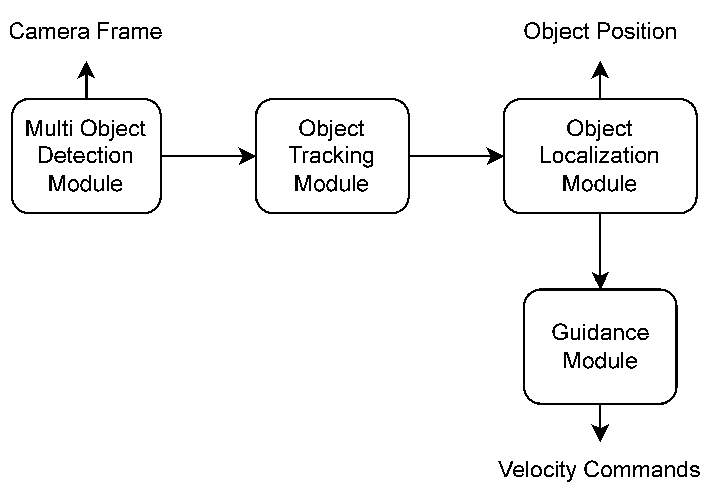
In this system, the drone is visiting randomly generated waypoints until it detects a person. The drone then follows the detected individual for a certain amount of time. The drone’s camera frame is sent to the multi-object detection module, which produces the bounding boxes of the detected objects, each of which carries the following information (label, confidence, x-center, y-center, width, height) and is sent to the object tracking module. The object tracking module assigns a unique id to each detected object and communicates this information with the object localization module in order to locate the object in world coordinates. The guidance module directs the drone to follow a given object by utilizing the object tracking module’s data and the drone’s attitude as input. The system architecture is presented in
Figure 1.
3.1.2. Global Tracker
Based on the architecture presented above, we created a system that utilizes a global tracker. The global tracker is an entity capable of localizing, tracking, and distinguishing objects detected from different sources.
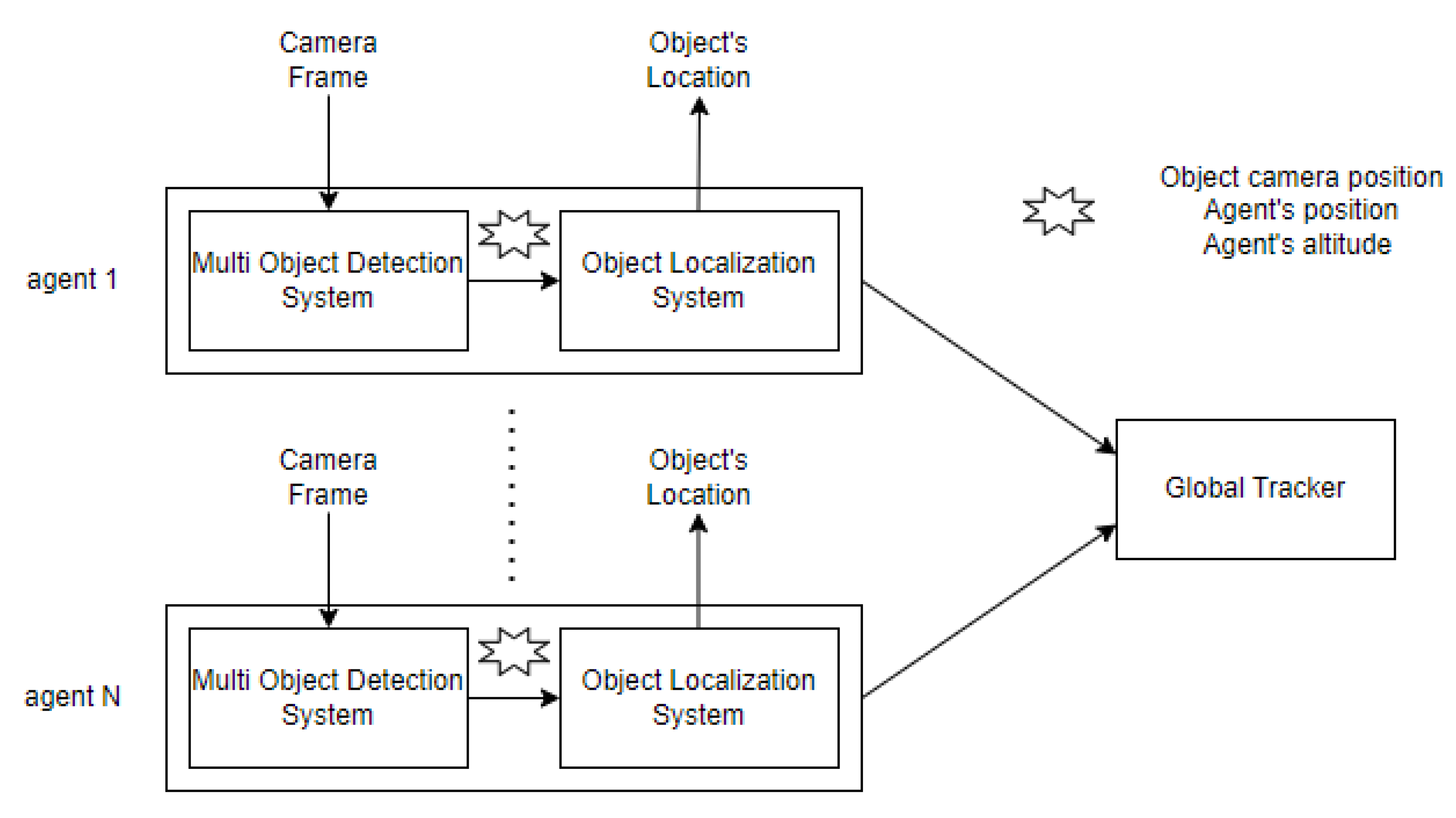
As presented in
Figure 2, in our system we have multiple agents, detecting and localizing objects as described above. Each agent passes its object localization outcome (cartesian coordinates) to the global tracker, to produce the desired output regarding information about the objects in the area. The tracker is processing this information using a sophisticated algorithm to distinguish the unique observations produced by the cameras of the four drones and monitor this particular area’s objects by showing the unique objects that are in it.
3.2. Object Detection
In this section, we explain the YOLO architectures we use in our Multiple Object Detection system. In particular, we deal with YOLOv4-608 and YOLOv4-Tiny, custom YOLOv4 implementation and state-of-the-art architecture, and YOLOv7-Tiny [
15]. The developers of YOLO [
16] made multiple object detection a single regression problem, straight from image pixels to bounding box coordinates and class probabilities prediction using anchor boxes. The convolutional network predicts, at once, multiple bounding boxes and class probabilities for those anchor boxes and is trained on full images and directly optimizes detection performance providing several benefits over other traditional methods of object detection, such as extremely fast execution, it implicitly encodes contextual information about classes as well as their appearance, learns generalizable representations of objects. This network uses features from the entire image to predict each bounding box. It also predicts all bounding boxes across all classes for an image simultaneously. This means YOLO reasons globally about the full image and all the objects in the image.
YOLOv7-Tiny which is based on the newest YOLOv7 [
15] algorithm has been implemented by the same developers and surpasses all previous object detection models and YOLO versions in both speed and accuracy as claimed by the authors. By making optimization changes to the backbone, they opt for layer aggregation using E-ELAN, an extended version of the ELAN computational block. Moreover, YOLOv7 employs re-parameterization planning techniques on the backbone to improve the ability of the model to generalize. To identify which modules should use such a strategy, gradient flow propagation paths are used. Lastly, when it comes to the head of the model, an auxiliary head using features roughly from the middle of the backbone is supervised during the training process and fine-tuning is performed by experimenting with different magnitudes of supervision on it. These, along with other changes, have produced state-of-the-art detection results along with great performance scaling as the model input increases. It requires cheaper hardware than other well-known architectures and requires less time in training since it can be trained on small datasets without any pre-trained weights. The major changes this architecture introduces regarding previous versions are the extended efficient layer aggregation network, model scaling for concatenation-based models, planned re-parameterized convolution and coarse for auxiliary and fine for lead loss.
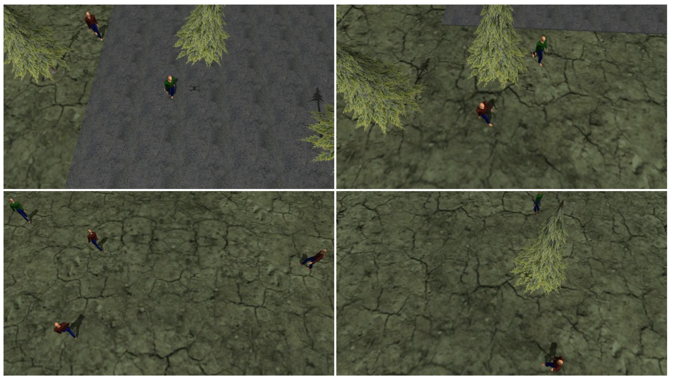
We develop datasets by flying drones and recording camera frames throughout their flights, as well as having individuals perform random walks in the area, and then annotating each image with the necessary information (label, x-min, y-min, x-max, y-max) for each object in the image. For the training dataset, 14 instances with varying views and altitudes were gathered. In
Figure 3, images from the training dataset are presented.
Both YOLOv4-608 and YOLOv4-tiny have been trained on the darknet framework, whilst our custom YOLOv4 was developed and trained in Keras [
17] and YOLOv7 was trained in Pytorch [
18]. We train on the actor dataset for 6000 batches and make the necessary changes in the models to detect one class. After experimentation, it was proven beneficial to use mosaic augmentation, increase hue shift to 0.4 from 0.1, and jitter augmentation on the YOLO head from 0.3 to 0.5. The models were trained and tested on a 608 by 608 tensor input. Inferencing was also conducted on the darknet framework to maintain the integrity of the system in terms of detection performance. The bounding boxes were saved in text format and later fed to the deep sort tracker for final validation.
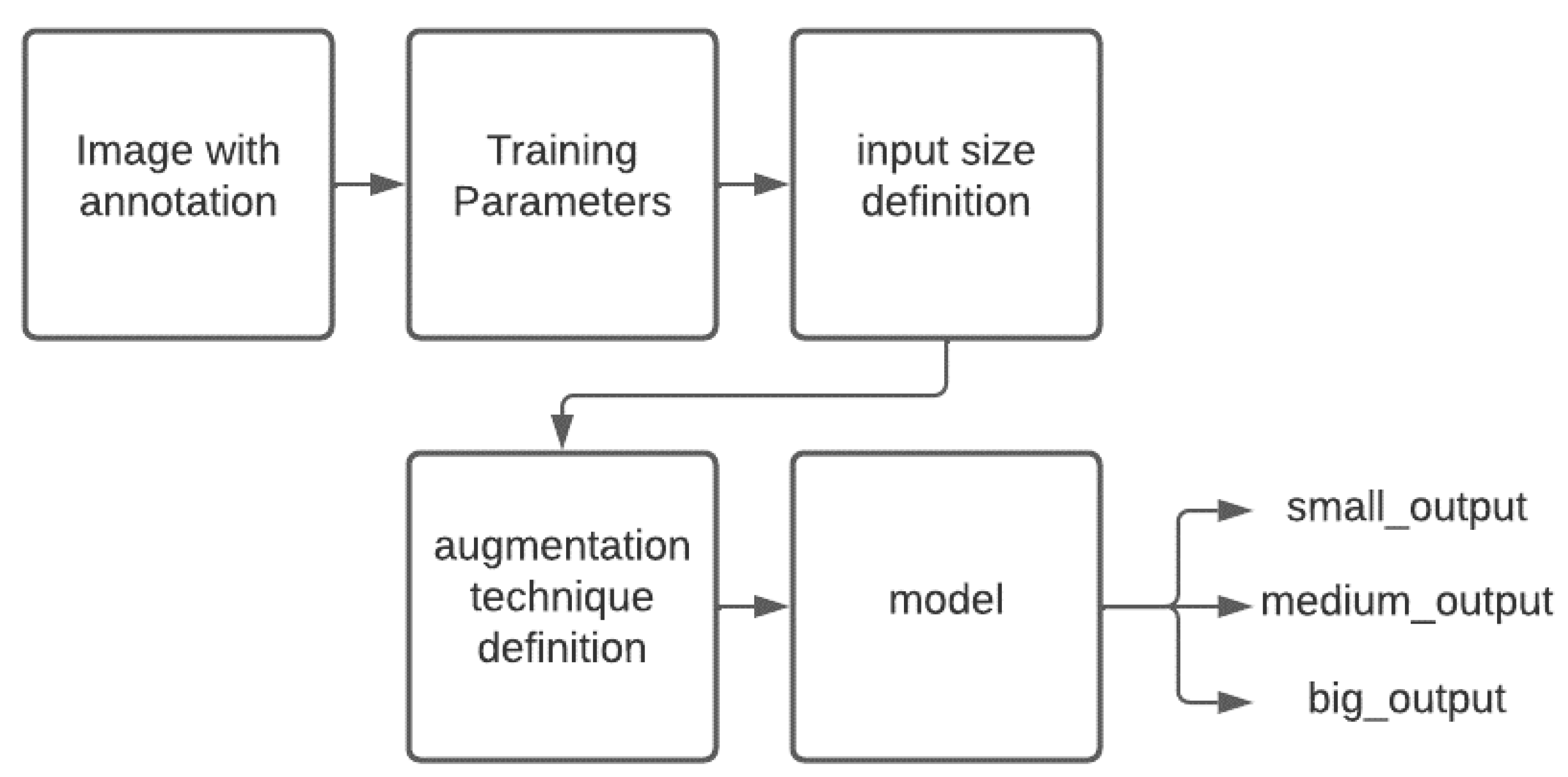
For our custom YOLOv4, we decided to keep the head as it is and make predictions in three scales similar to YOLOv4, but we make a significant reduction to the model’s backbone. The backbone we use has 88 layers instead of 138 of the original YOLOv4 resulting in 4.7 million parameters, where there is a reduction of 60 million in the number of parameters between the two models.
Figure 4 shows the flow chart of the training procedure of our network.
The model’s data generator parses the annotated image before choosing random images for each image in the batch size and choosing a random input size from the available train sizes for each image in the batch size [416, 448, 480, 512, 544, 576, 608, 640, 672, 704, 736, 768, 800, 832], and the bounding box transformation is applied. Following that, one of the available augmentation techniques is chosen (random-rotation, random-horizontal-flip, random-change in Hue) and the bounding box transformation is applied. The parameters used in the training of the network are presented in
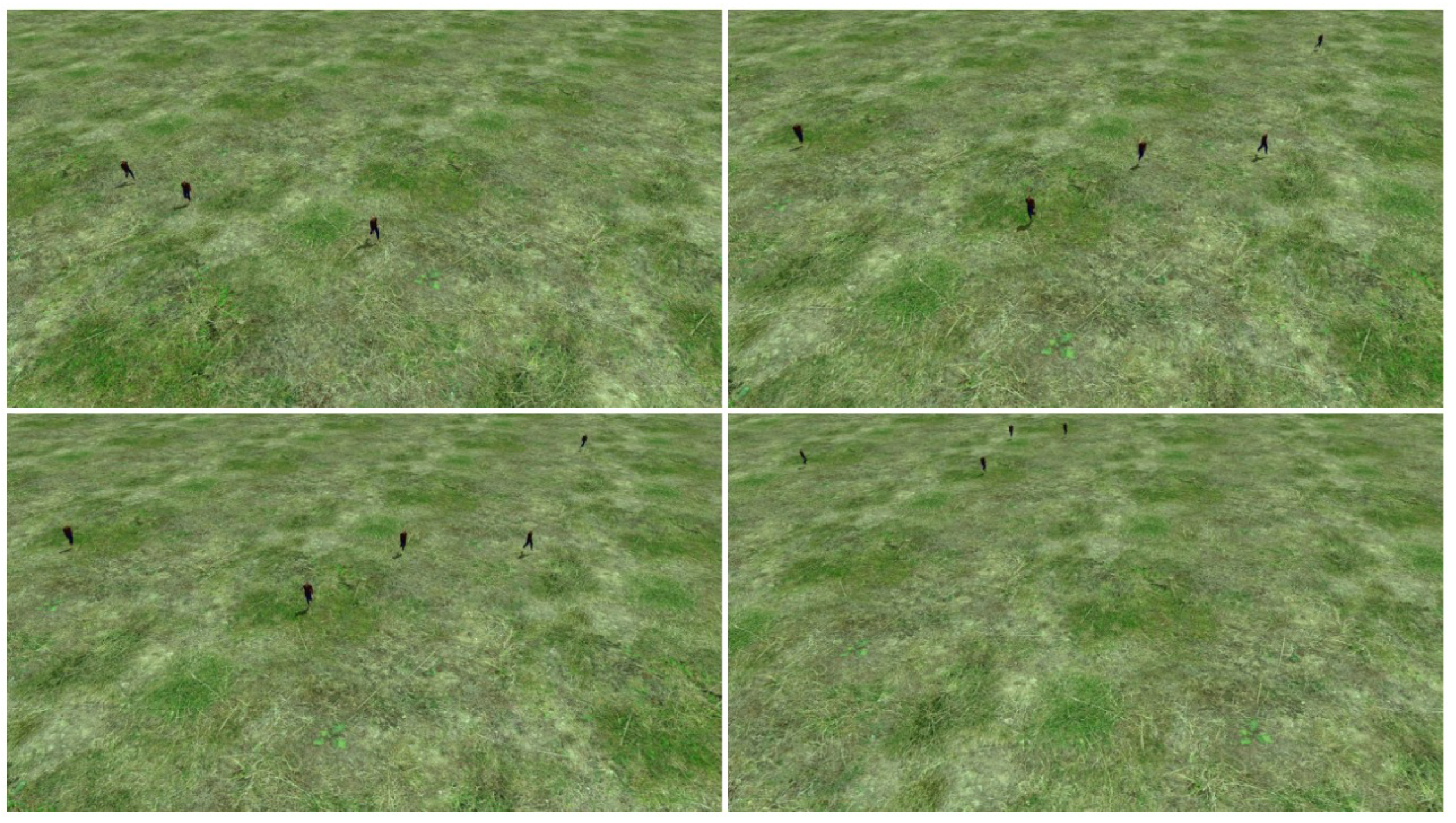
Table 1. Finally, 872 images with a completely different background were collected for the validation dataset so that we could assess how well the object detector generalizes. Except for the images made via mosaic augmentation, all images are 1280 pixels wide by 720 pixels in height. Our train dataset has 3160 photos, whereas our test dataset contains 872 images. In
Figure 5, images from the test dataset are presented.
3.3. Object Tracking
Another benefit of using these schemas is that their outputs (i.e., bounding boxes) can be used for tracking objects and deriving speed information relative to the drone’s position. For this task, there is a very well-known algorithm called Deep SORT [
19]. One of the most popular object-tracking frameworks is Deep SORT, which improves tracking and reduces the number of identity changes by integrating an appearance feature vector for the tracks, which, in this example, is produced by a pretrained CNN using the bounding boxes detected by YOLO. There is a demand to develop new ways to keep track of them and accurately identify them because basic detection models are extremely likely to fail at identifying many objects sequentially as the frames pass. Deep SORT is utilized here to provide a good MOT (multiple object tracking) [
20] foundation.
The Kalman filter is an important part of Deep SORT. Because we use a basic linear velocity model, the state simply stores the absolute position and velocity components. The Kalman filter helps us account for noise in detection and predicts a suitable match for future bounding boxes based on past states. The next difficulty is linking new detections that are coming from YOLO with the predictions that have been made from the Kalman filter. Because they are handled separately, a technique to link track i to incoming detection k is required. Deep SORT provides two things to address this; (1) an efficient method to associate the data and (2) a distance metric to quantify the relationship. To include the uncertainty from the Kalman filter, the authors choose to utilize the squared Mahalanobis distance (an effective measure for dealing with distributions). This threshold can provide us with a good estimation of the real linkages. Since we are measuring the distance between two distributions, this metric is more accurate than, for example, the Euclidean distance. The Hungarian method is utilized for the data association component. Finally, the feature vector serves as the object’s “appearance descriptor”.
It is possible to lose track during tracking owing to obstruction, sudden changes in measured velocities, or poor detector performance. We have modified SORT settings to remedy this situation. The parameters we modified are the maximum age of a track has been raised from thirty frames to sixty frames, while the minimum number of frames necessary for a track to be considered active has been raised from three to seven. Finally, while tracking, we save the image coordinates of the bounding box, and if it is lost, we use the closest() method, which will try to identify and follow the track that is closest to the lost one and no more than 10 percent off on each axis. If the original track and a track similar to it are not found for the maximum-age frames, we consider the track lost. If closest() located a track and did not miss it for max-age frames, we switch to that track at the conclusion of max-age frames and consider it an identity switch. This approach works effectively in areas with a moderate invader density.
3.4. Object Localisation
The object localization algorithm is invoked when the target has been detected to determine the target position. The algorithm’s inputs are the drone’s position , the drone’s attitude and the pixel coordinates of the lower centre point of the bounding box of interest. The estimated target’s position is the output of the algorithm. Furthermore, the camera intrinsic parameters and the frame size are assumed to be known. Since we are using a quadcopter with a stabilizing camera gimbal, the camera’s pitch value may be assumed to be constant and the roll value to be zero.
The object localization steps are presented below:
3.5. Drone Guidance
After object detection and tracking are finished, the user is shown the camera’s image feed and given the option to select a particular tracked object from the screen for the drone to follow. Then the guiding system will transmit velocity and yaw commands based on the position of the bounding box on the screen. We use the central point of the bounding box in both axes as a guide and measure its distance from the centre of the screen in both axes. The system can also run in headless mode, which does not require user input and lets the drone follow the first target spotted.
The drone’s altitude is assumed to be constant. The drone’s guidance commands are designed so that the tracked target stays in the centre of the camera’s field of view. To achieve that the velocity in the x and y axis
and the desired yaw
are computed as shown in Equations (
13) and (
14).
where
are the pixel coordinates of the centre of the image and
are the pixel coordinates of the centre of the bounding box in the image.
The speed values and yaw value are smoothed considering their previous values before being sent to the drone’s firmware to prevent abrupt movements to help Deep SORT build trajectory data, therefore reducing identity switches.
3.6. Global Tracker
In this section, the global tracker system is presented. The global tracker is an entity capable of localizing, tracking, and distinguishing objects detected from different sources. As presented in
Figure 2, in our system we have multiple agents, detecting and localizing objects as described above. Each agent passes its object localization outcome to the global tracker, to produce the desired output regarding information about the objects in the area. The tracker is processing this information using a custom algorithm to distinguish the unique observations produced by the cameras of the four agents. The output of the localization system of each agent is fed to the global tracker system. The observations are processed and then passed to the well-known object tracking algorithm SORT, but instead of giving the camera’s pixel coordinates of a single agent to the SORT algorithm we provided the processed observations of the agents in Cartesian coordinates and fine-tune the SORT algorithm regarding specific parameters like the max-age of detection that can be used in memory and the IOU threshold.
After having performed the pre-processing step seen in Algorithm 1, the detected objects are then associated with tracks based on the location and size of the objects in the current and previous frames. The algorithm uses a Kalman filter to predict the location of each track in the next frame and then uses a Hungarian algorithm to associate the predicted tracks with the detected objects in the next frame. This process is repeated for each timestep during execution, allowing the algorithm to track multiple objects as they move over time.
| Algorithm 1 Detections Selection Algorithm |
- 1:
for Detections in a particular timestep do - 2:
while do - 3:
Calculate distance matrix for all detections - 4:
Find the pair of detections with the minimum distance - 5:
Using that pair, create a cluster with the nearby detections having a distance <2 m - 6:
Find the camera with the most detections in that cluster - 7:
if Another camera has the same number of detections then - 8:
Find the closest camera of that detection - 9:
Keep the detections from the closest camera and remove the others in that cluster - 10:
else - 11:
Keep those detections and remove the others in that cluster - 12:
end if - 13:
end while - 14:
end for
|
The SORT algorithm has several advantages over other visual tracking algorithms in our use case. It is relatively simple to implement and can run in real-time even with a high number of detections, making it suitable for use in applications with strict performance requirements. It also uses a combination of detection and data association, which allows it to handle occlusions, false detections, and other common challenges in visual tracking.
3.7. Tools
The proposed system was implemented in C++ and python. For the drone’s guidance and control, a Robot Operating System (ROS) [
21] was utilized. ROS is an open-source robot operating system, designed to handle process management and scheduling. The system was evaluated in the Gazebo [
22] simulator using the PX4 autopilot [
23]. Gazebo is an open-source, powerful physics engine, capable of simulating 3D dynamic multi-robot environments.
Training and inferencing of our object detection models are accelerated on CUDA-enabled GPUs. Darknet [
24] built with CUDA [
25] support is being used for the YOLOv4-Tiny and YOLOv4-608 models with their default layers. For the YOLOv4-Custom model, we use Keras with TensorFlow [
26] backend to create, train and perform inference on images. For the YOLOv7-Tiny model, we perform training and inferencing using PyTorch.
All metrics have been generated using tools written in python. Testing was conducted on the same machine, equipped with an Intel Core i7-8700K, 16 Gigabytes of RAM, and an NVIDIA GTX 1070 GPU based on the Pascal architecture.
4. Results
4.1. Object Detection
All four object detectors, YOLOv4-608, YOLOv4-Custom, YOLOv4-Tiny and YOLOv7-Tiny have been trained with our custom train dataset and tested on the same test dataset mentioned in the previous section to evaluate their performance. For the object detection subsection we provide the following metrics:
Total positives;
True positives;
False positives;
False negatives;
Recall;
Precision;
F1-Score;
Average precision.
As seen in
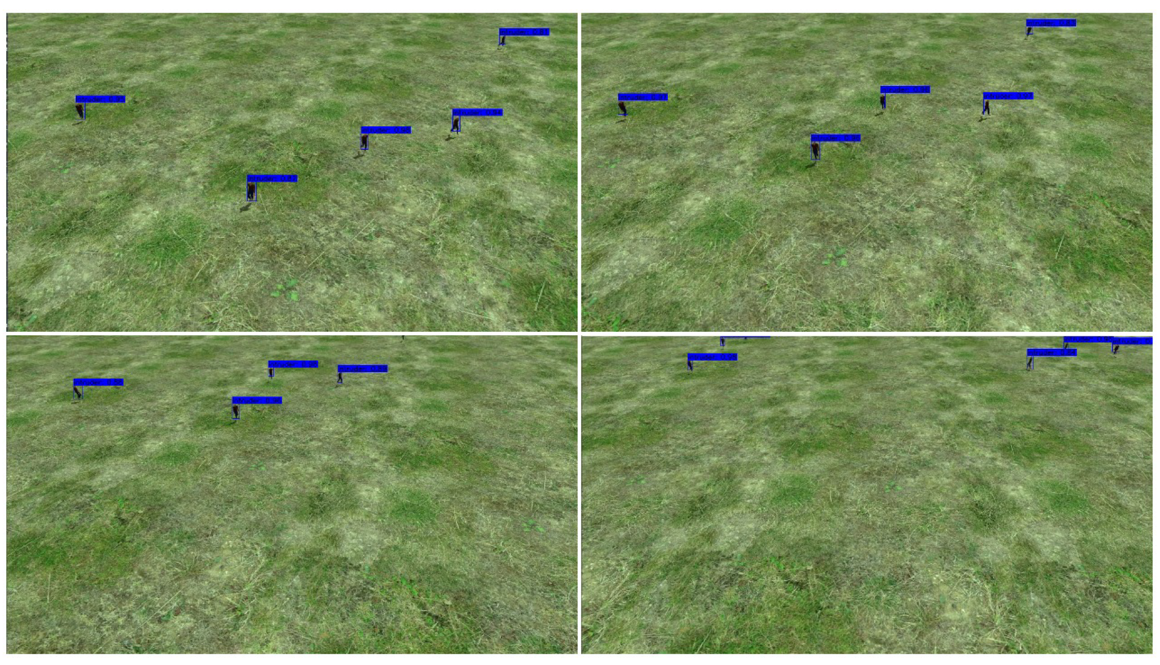
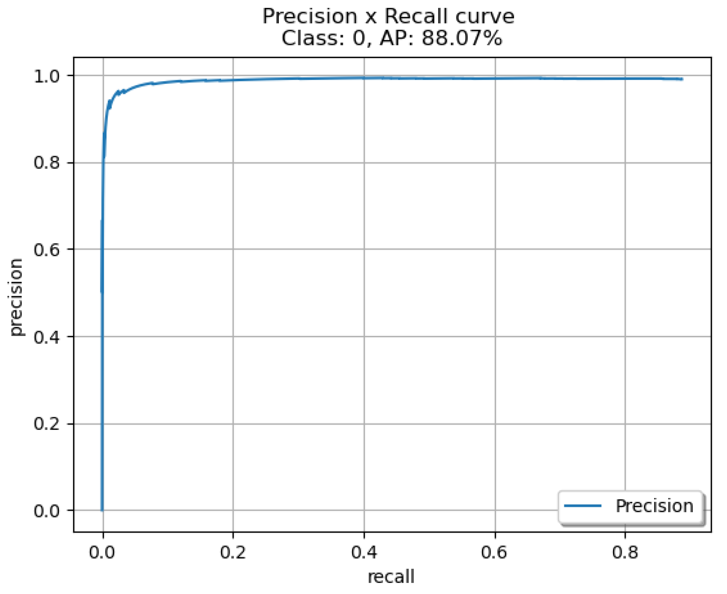
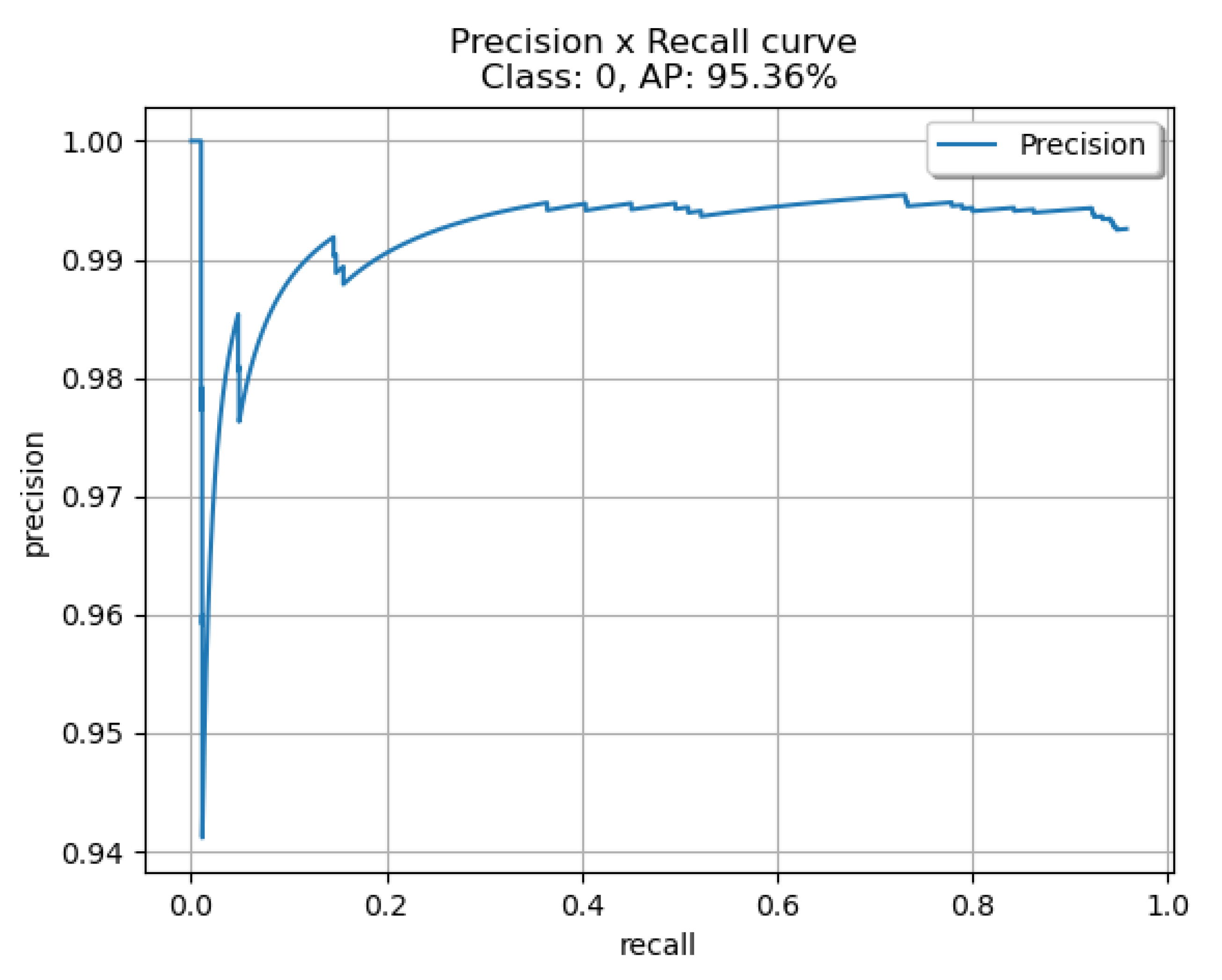
Table 2, YOLOv4-Custom and YOLOv4-608, trained on the custom dataset we created, offer similar detection performance with an average precision of 94.36% and 95.36% respectively. YOLOv4-Tiny has an average precision of 88.07% which makes it a great candidate in computationally constrained scenarios. Our custom YOLOv4 model trained and created in a Keras environment is significantly smaller when compared to YOLOv4-608 while offering similar detection performance, but we can observe that YOLOv7-Tiny outperforms all other models with an average precision of 98.04%. In
Figure 6, detection results of the custom YOLOv4 are presented.
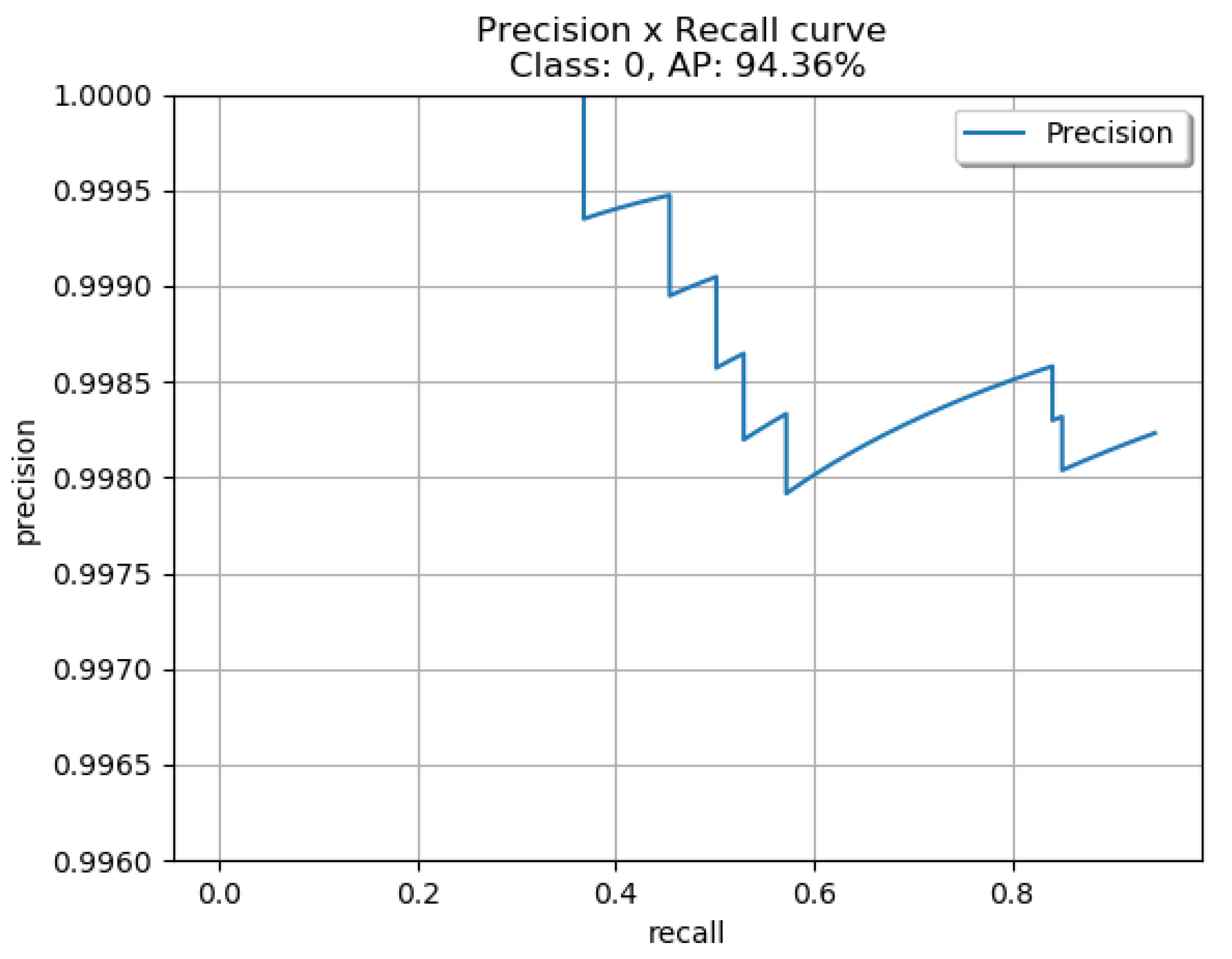
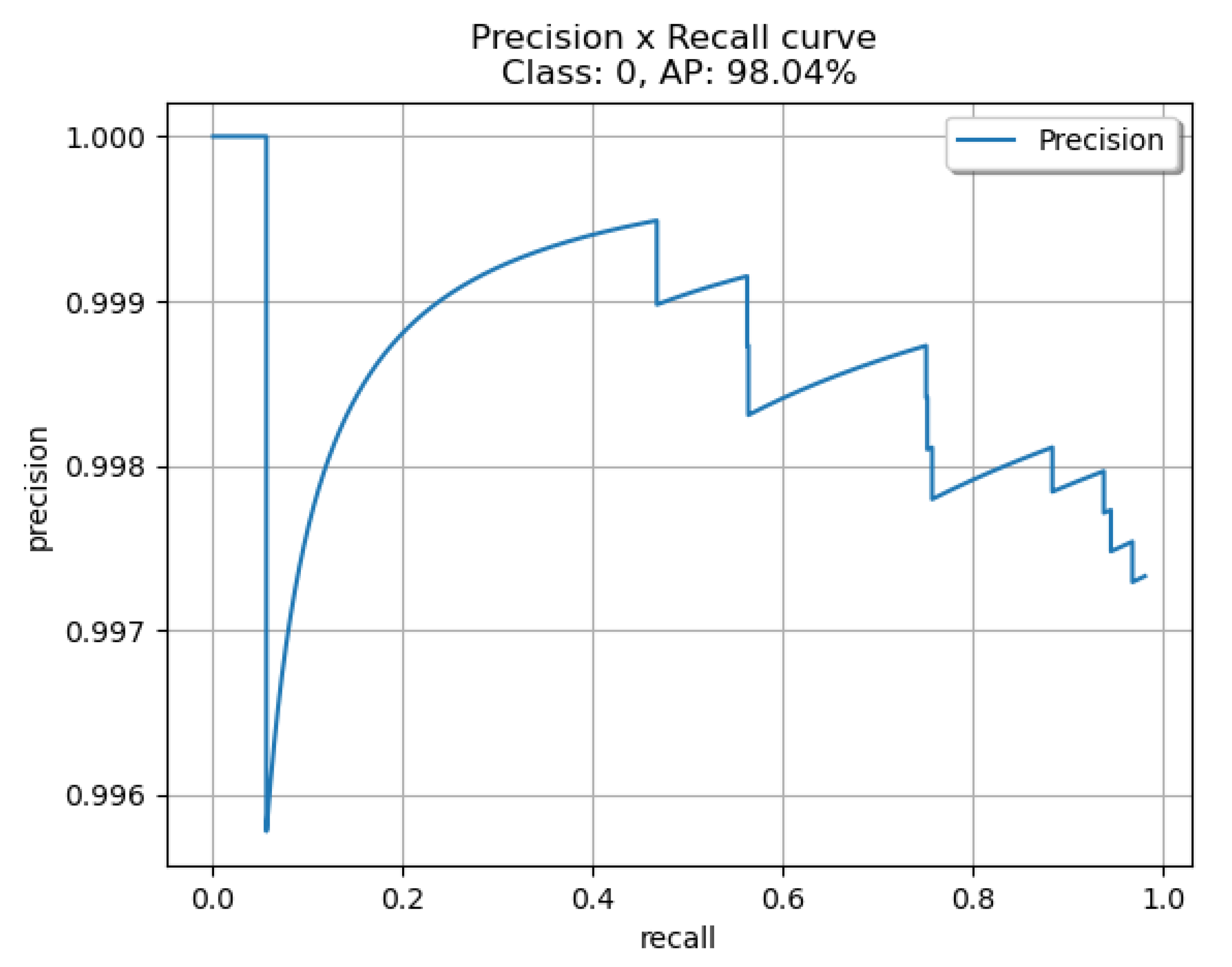
To help in the evaluation of the four different networks we produced the ROC curves for each network. In
Figure 7 the curve for the custom network is presented, in
Figure 8 for the YOLOv7-Tiny, in
Figure 9 for YOLOv4-Tiny, and in
Figure 10 for the YOLOv4-608. The curves indicate that the YOLOv7-Tiny outperforms all other networks as expected. Another important metric to evaluate the four networks is the capability of running in real-time, hence the inference time for every model was measured. YOLOv4-608 was measured to have 46.4 ms inference, YOLOv4-Tiny was measured to have 6.6 ms inference, YOLOv4 custom was measured to have 19.7 ms inference and YOLOv7-Tiny was measured to have 10.9 ms inference.
4.2. Object Tracking
To assess tracking performance, we also issue MOTA, MOTP, and MOTAL scores along with the number of identity switches during tracking as seen in [
20]. The MOTP measure is defined as the total position error for matched object hypothesis pairings over all frames, multiplied by the total number of matches made. It demonstrates the tracker’s capacity to predict accurate item locations, regardless of its ability to recognize object combinations, maintain consistent trajectories, and so on. Out of all frames, MOTA accounts for all object configuration mistakes produced by the tracker, including false positives, misses and mismatches. It provides an intuitive assessment of the tracker’s ability to maintain precise trajectories, regardless of its accuracy in calculating object locations.
Once again, our custom YOLOv4 model outperforms YOLOv4-Tiny and YOLOv4-608, offering a MOTA score of 88.2 and an MOTP score of 93.3 but YOLOv7-Tiny proven to be better with a MOTA score 95.7 and an MOTP score of 94.7. YOLOv4-Tiny and YOLOv4-608 had a MOTA score of 69.9 and an MOTP score of 90.1, as seen in
Table 3.
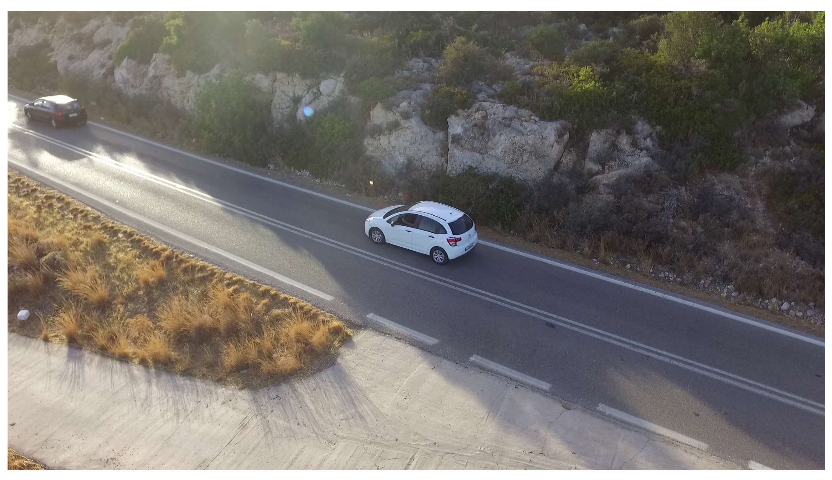
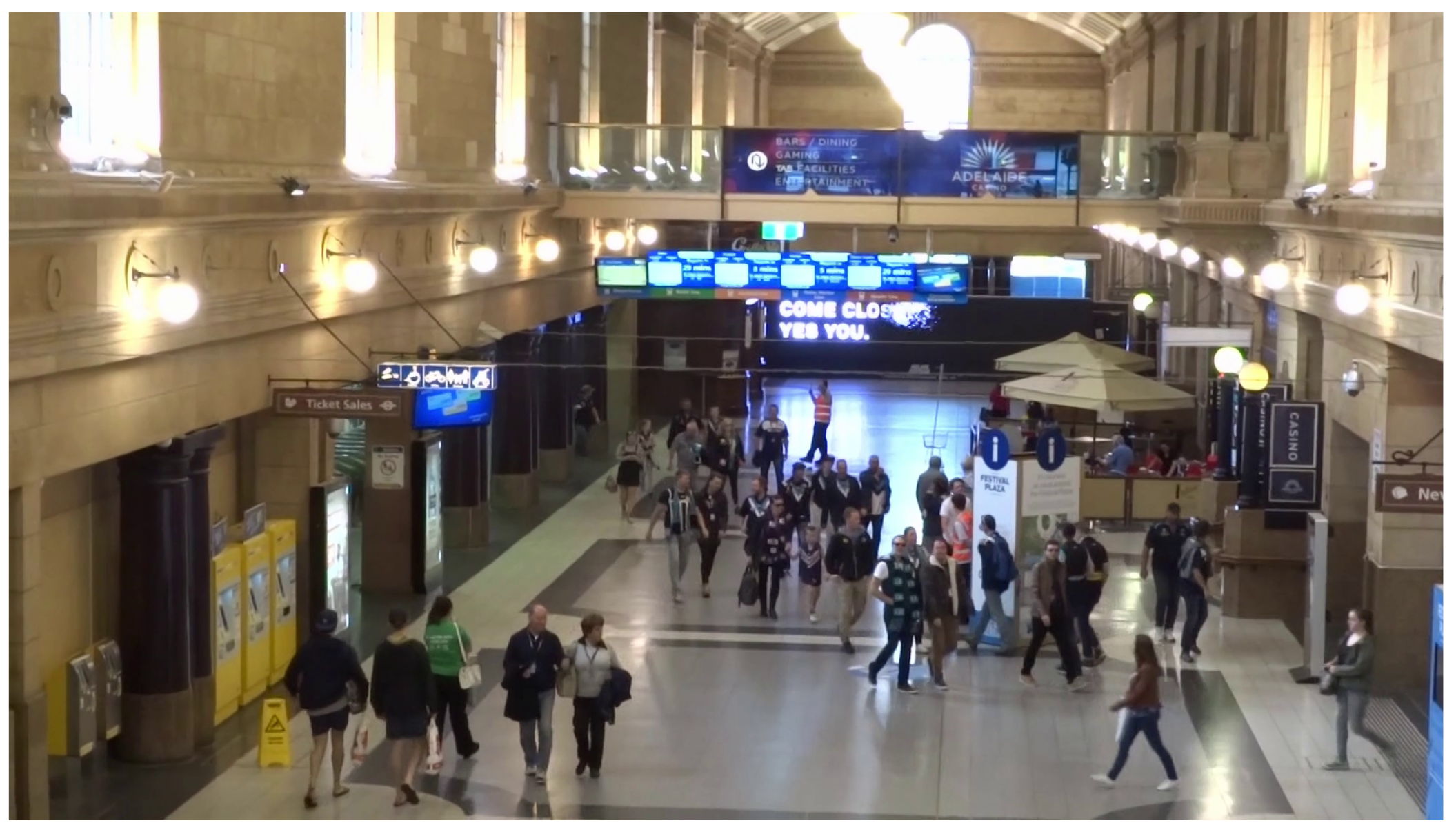
To validate our best model YOLOv7-Tiny, we decided to test it in real-world videos, the “MOT20-01” scene and the rural road scene. To do so, we trained the model using the well-known VisDrone [
27], a large-scale drone-based dataset containing 8.599 photos (6.471 for training, 548 for validation, and 1.580 for testing) capable of multiple object detection for the following 10 object categories (pedestrian, person, vehicle, van, bus, truck, motor, bicycle, awning-tricycle, and tricycle). The “MOT20-01” scene from the MOT20 [
28] dataset is used, which is another commonly known dataset for object tracking algorithms. It is an indoor scene in a packed railway station. It’s a very challenging scenario, with 25 frames per second and 1080p resolution. The duration is 17 s and 90 people in total in this video. The “rural road” is a scene captured by a drone on a public road with real-world traffic. We used the DJI Phantom 3 drone to record a 15 min video of public road traffic at 1080 p and 25 fps. We removed the areas of the video where there was no traffic, and we reduced it to one minute and six seconds. The video contains objects of automobiles, vans, and pickup trucks. In
Figure 11 and
Figure 12 the two test scenes for real-world evaluation are depicted while in
Table 4 the metrics for these two scenarios are presented.
In both scenarios, we used the same parameters as in the simulated ones. Regarding the MOT20-01 scenario, we observe a lot of identity switches and it is caused by our decision to keep the IOU threshold the same for all the tests we performed. The high detection density of this scene causes a lot of occlusions and overlaps between the detected bounding boxes. Regarding the rural road scene, the combination of YOLO7-Tiny and DeepSort performed really well, having a small number of identity switches and a score that indicates near-perfect tracking.
4.3. Object Localisation
Our camera is pitched by 53.2392 degrees and the algorithm outputs the estimated target’s position which during simulations was logged. We can also extract the actual position of the target through Gazebo for that moment, which allows us to measure the deviation from the ground truth of the estimated position. Since we base the prediction on the coordinates given by the bounding box output of YOLO, accuracy is also affected by the accuracy of the generated bounding boxes. After extensive simulation, we have gathered more than 500 samples measuring the Euclidean distance between the two points and present the results in
Figure 13.
The object localization subsystem achieves a geometric mean of 0.205 m with the highest error reported being 1.18 m. The vast majority of the results fell into the 0 to 0.3 m range, occurring 72.6% of the time. A loss of 0.3 to 0.6 m occurred only 16.7% of the time and an error of 0.6 to 0.9 m was at just 7.1% likewise. Lastly, a loss of 0.9 to 1.2 m took place only 3.6% of the time. An error is expected since our camera is pitched and not in a top-down view.
4.4. Guidance
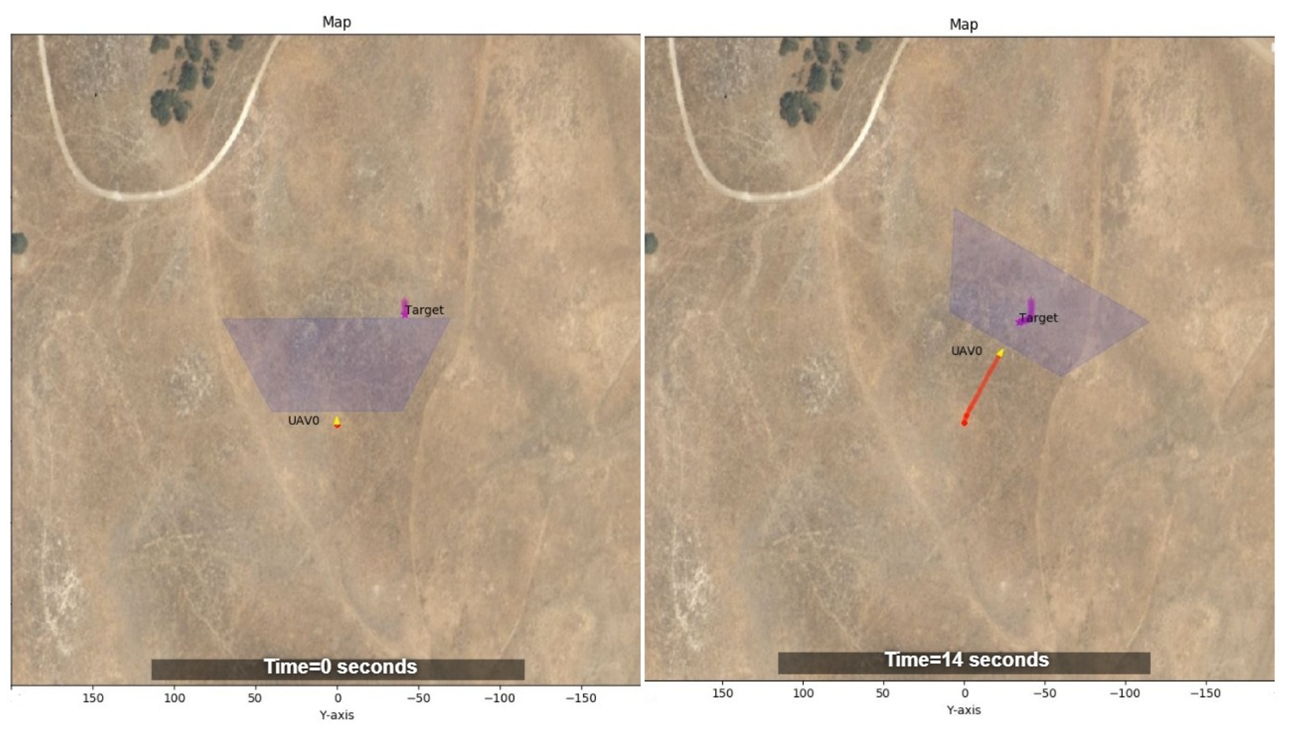
In this section, we have plotted the trajectory of a single UAV and a target that is performing a random movement with the end goal of reaching the middle of the map. The yellow arrow corresponds to the location of the UAV in real time and the red line logs its trajectory. In purple, the location of a target is shown and the trapezoid in light blue displays the area covered by the drone’s camera.
In
Figure 14, we present two parts of the simulation. At first, labelled as initial detection with a time equal to 0 s, the target is just about to enter the drone’s camera field of view. Right after that, the drone begins to approach the target which is shown on the right part of
Figure 14, timed at 14 s.
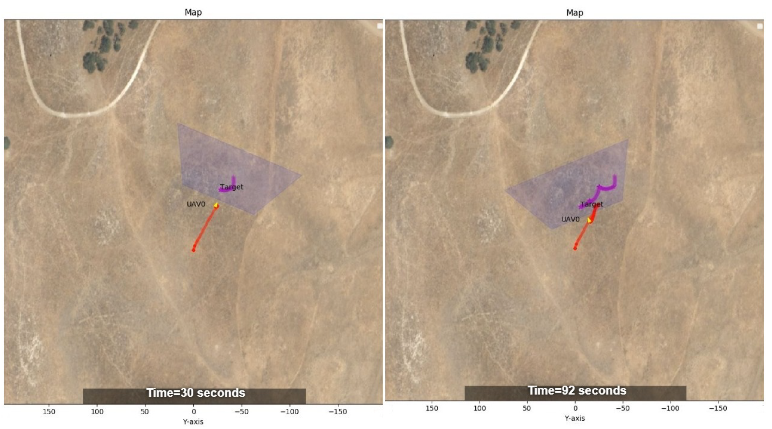
In
Figure 15, the UAV performance of following the detected target is depicted. This is a continuation of the previous capture from the same simulation. Timed at 30 s, the UAV has a lock on target and is closely following him by keeping him at the centre of the camera. In the right part of
Figure 15 and timed at 92 s the UAV has been following the target for over a minute and never lost track of it.
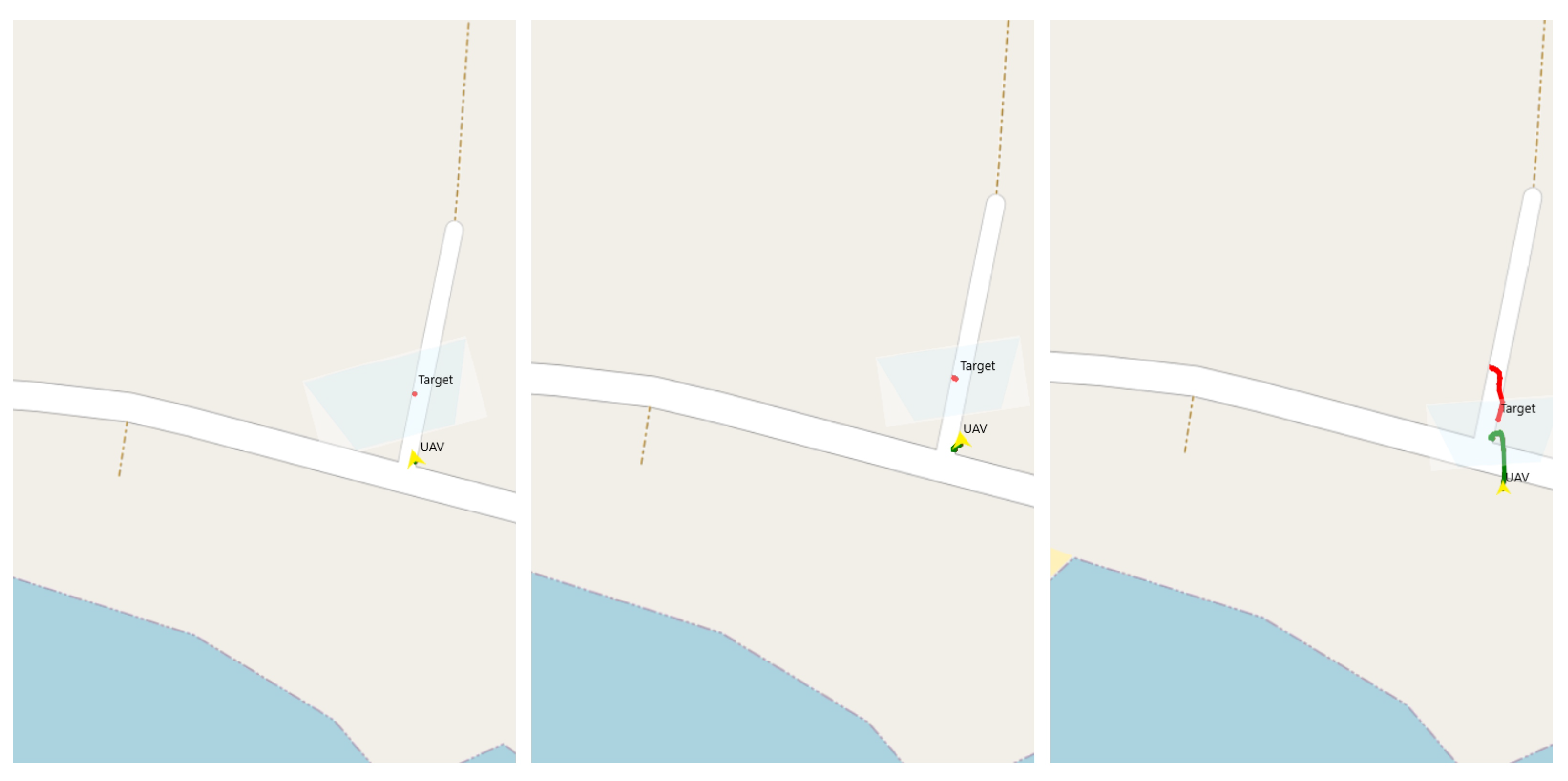
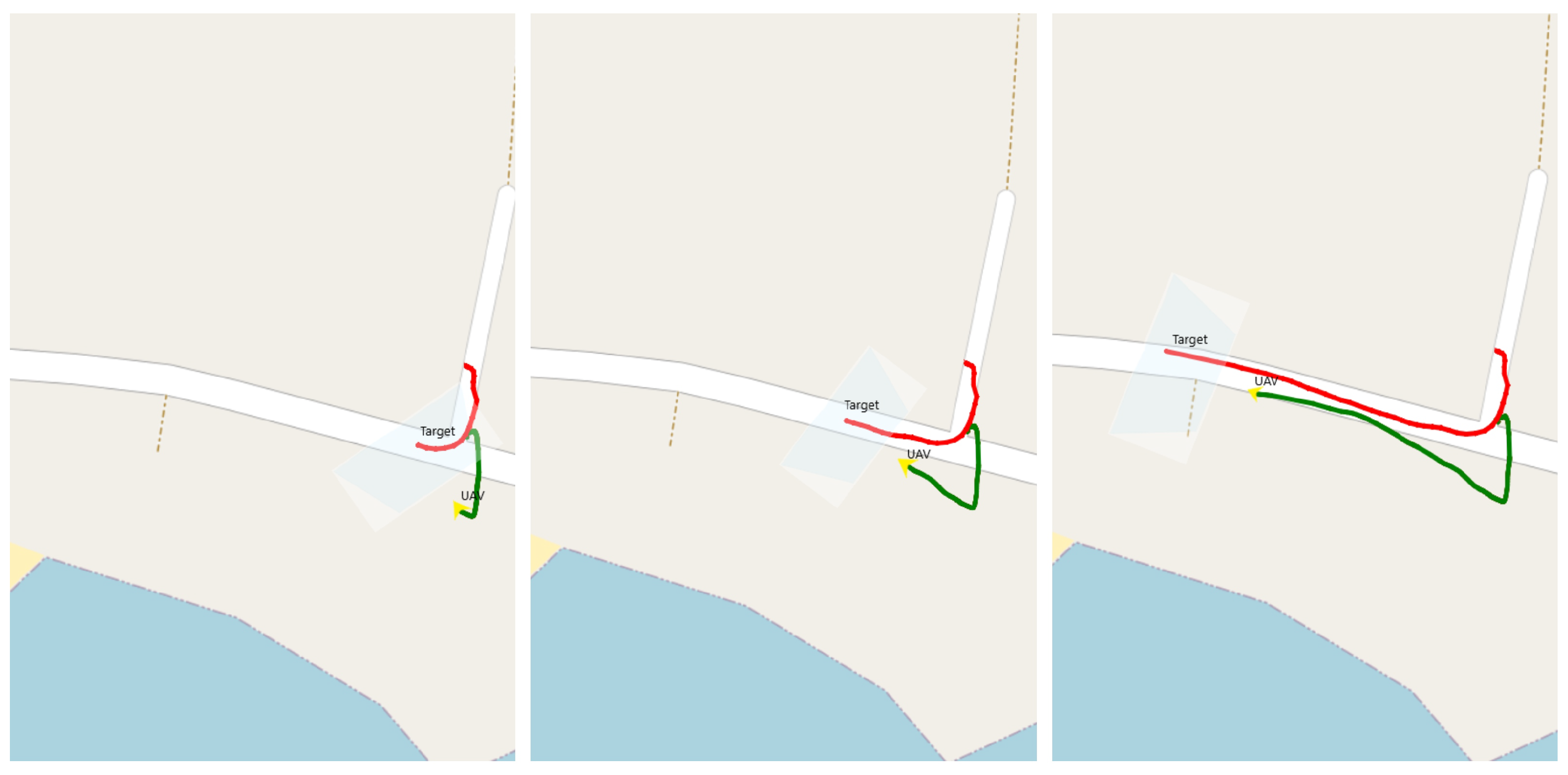
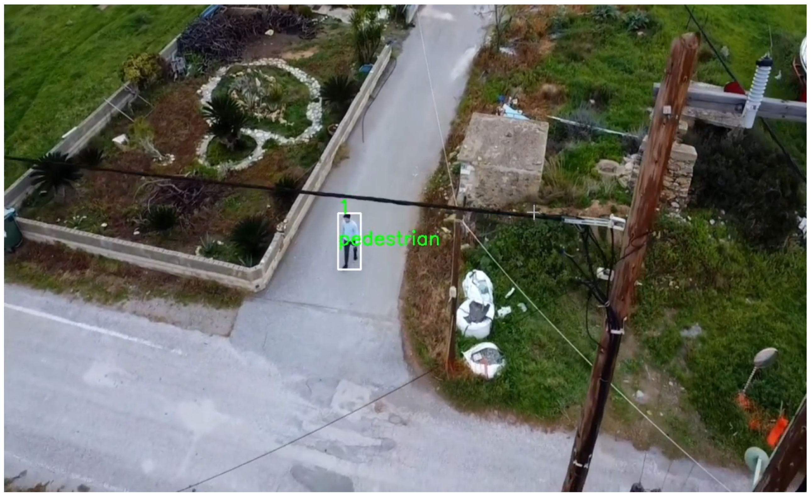
We also present a case, with a real-world scenario, utilizing a DJI Mini2 drone with our algorithms using the DJI mobile SDK. For object detection tracking we used the same framework as in our ROS simulation and in the MOT-20 and rural road scenes, YOLOv7-tiny and DeepSORT trained on the VisDrone dataset.
In
Figure 16 and
Figure 17, the trajectories of the drone (green) and the object (red) are presented alongside the field of view of the drone’s camera. In
Figure 18, the scene used for this scenario is presented, where a person walked through the road and the drone followed this specific person. We can observe that our system tested in the simulations, is also efficient in this simple real-world scenario as the only difference is that we trained the system with the VisDrone dataset to detect real objects. The guidance algorithm used in this scenario is the same as the one used in the simulations.
4.5. Framework Performance
This section breaks down the compute-intensive parts of the system and measures their execution time to measure and prove that our system can be fast, scalable and reliable.
There are four components to the system. The first one is the preprocessing part, which gets the camera feed from the drone and converts it to a resized array, so the YOLO model can use it to make a prediction. The next component is inferencing. We measure the time elapsed for YOLO to perform inference on the image. The third one is the time elapsed for Deep SORT to assign the predicted objects the corresponding IDs. Lastly, the guidance section measures the time elapsed to calculate the appropriate velocity commands for every drone.
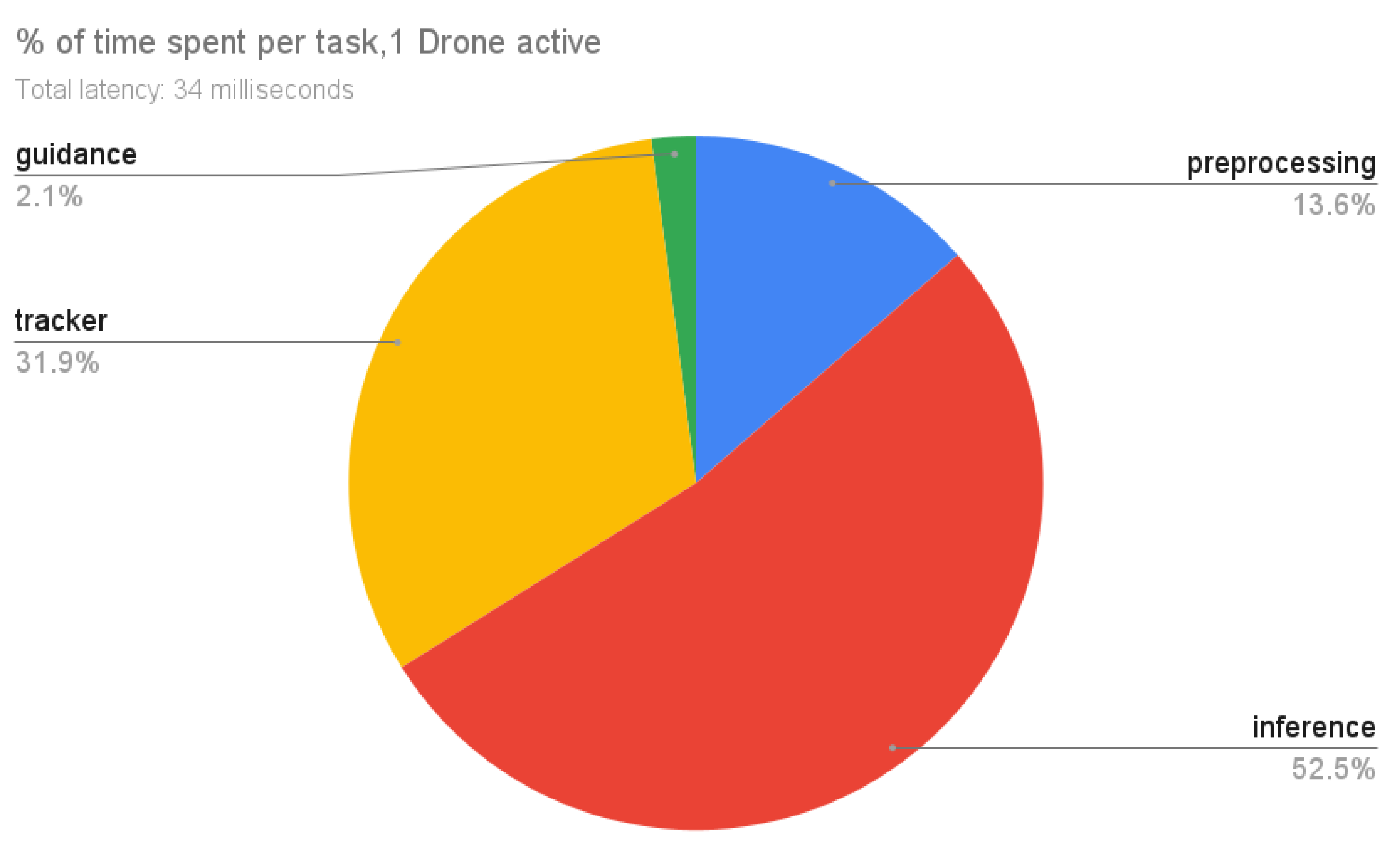
Regarding the results for one drone presented in
Figure 19, the system is completing a time-step in 34 milliseconds, a latency suitable for real-time tracking. We can see that most of the time was spent during inference which takes 52.5% of the time. Deep SORT is running for 31.9% of the time it takes to complete one time-step when using one drone and preprocessing takes just 13.6%. Finally, guidance is only responsible for 2.1% of the time spent.
As seen in
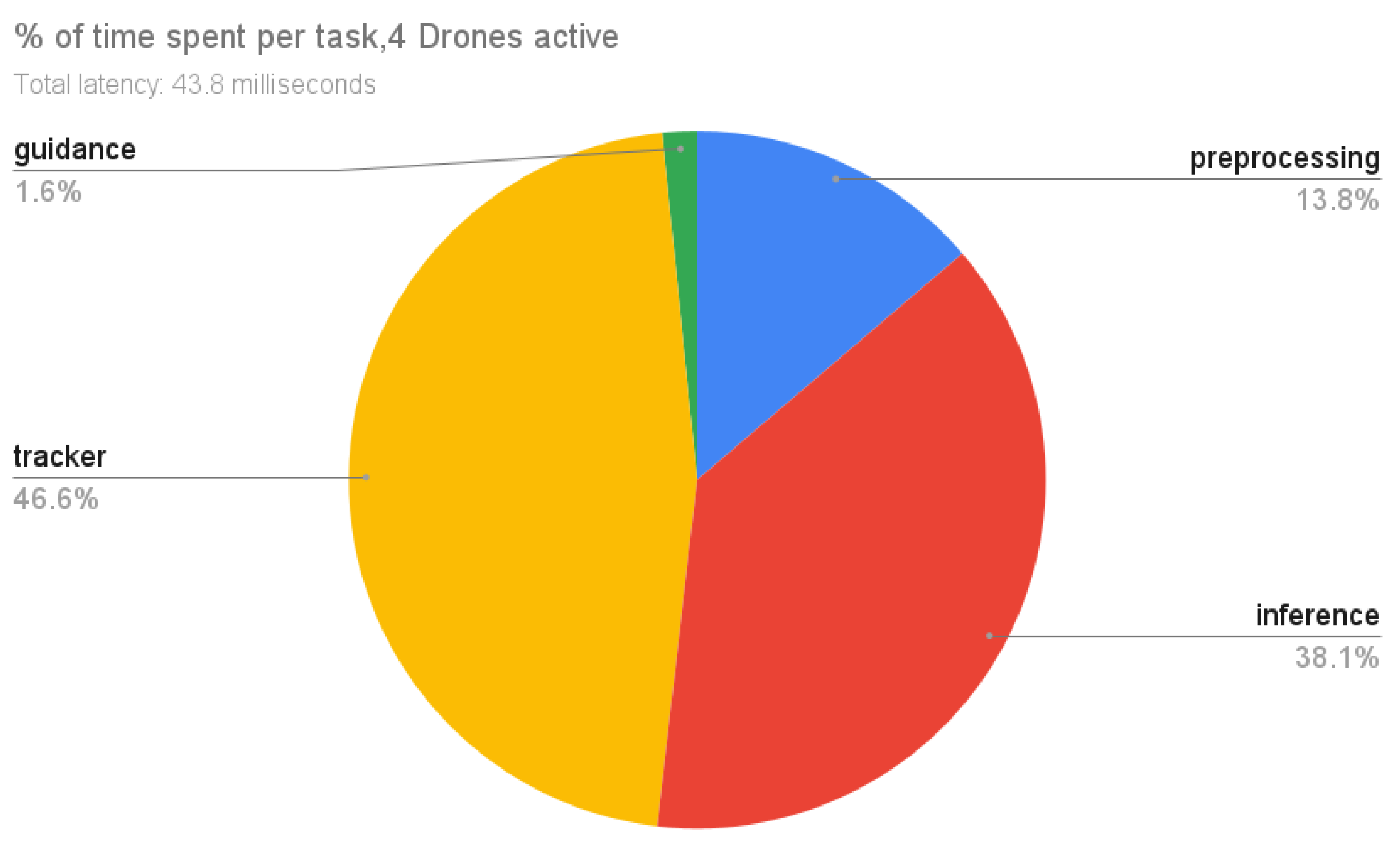
Figure 20, we observed that initializing four instances of YOLO in one simulation PC, is making it impossible for our system to run in real-time using the resources we had, so we decided to use one instance of YOLO with higher dimensions in input (832) and concatenate the images of four drones 640 × 360 into one and resize the stitched image to use in YOLO for predictions. Based on bounding boxes screen coordinates, we can identify which drone detected which object. We also perform tests using four drones. Here, the system can complete a time-step in 43.8 milliseconds, proving that the system can scale with more drones. Using four drones has caused the tracking time to now be our hotspot, taking 46.6% of the total time. This behaviour is expected due to significantly more tracks being computed from the addition of three more drones. Inferencing time remains stable and is responsible for 38.1% of time spent with preprocessing taking slightly longer at 13.8% due to the higher number of image feeds. Lastly, guidance remains fast at just 1.6% of time spent.
4.6. Global Tracker
In this section, the results of the Global Tracker are presented. The system is tested in several scenarios varying in the movement of the objects, the camera pitch degrees, and the movement of the cameras. The cameras in these scenarios are located in a rectangular shape and the actors are moving within this area. All scenarios had a pitched camera of 57 degrees except the ones that mention a different value. The scenarios are the following:
Cross path with no localization error: This scenario included six actors starting at positions around the centre of the world and all moving towards the centre, causing their paths to cross. After reaching the centre of the world the actors move back to their original positions. For this scenario, no localisation error was considered and the global tracker was fed the ground truth concerning the actor’s positions.
Straight line: In this scenario, the six actors were placed in a formation and performed a straight line path.
Random movement: This scenario included six actors performing a random path, crossing paths with another actor in several cases.
Random movement with a pitched camera: In this scenario, the actor’s behaviour is shared with the one in the “random movement” scenario, but the UAV’s camera is pitched at 25 degrees.
Cross path: In this scenario, the actors’ behaviour is the same as in the previous scenario, but in this case, localisation error is considered.
Static objects moving drones: In this scenario the actors are static and the cameras are moving aiming to detect the total number of actors in the area.
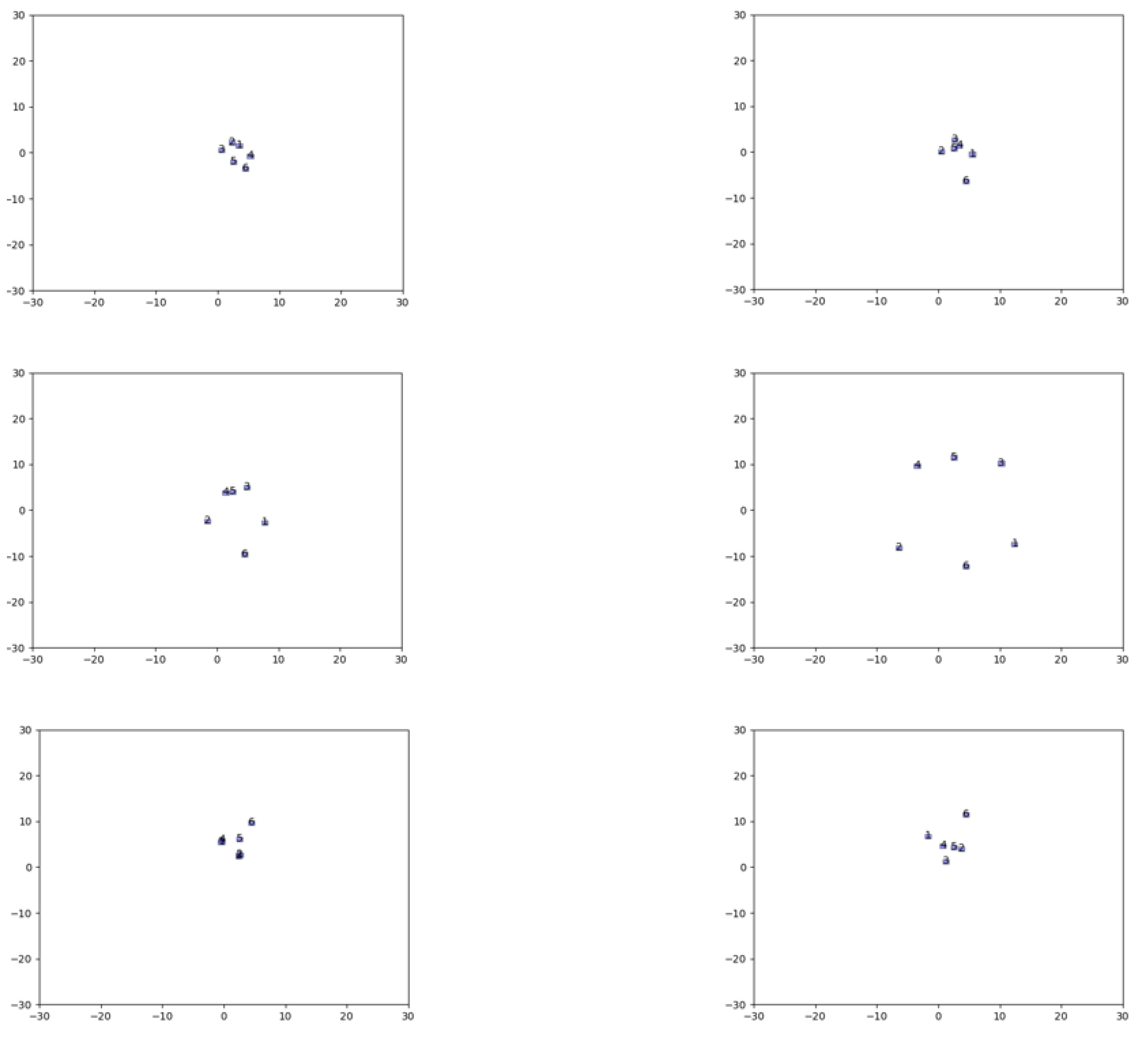
In
Figure 21, we see six different instances of global tracker presenting the locations of the detected objects and their unique id in the cross-path scenario.
In
Figure 22,
Figure 23,
Figure 24 and
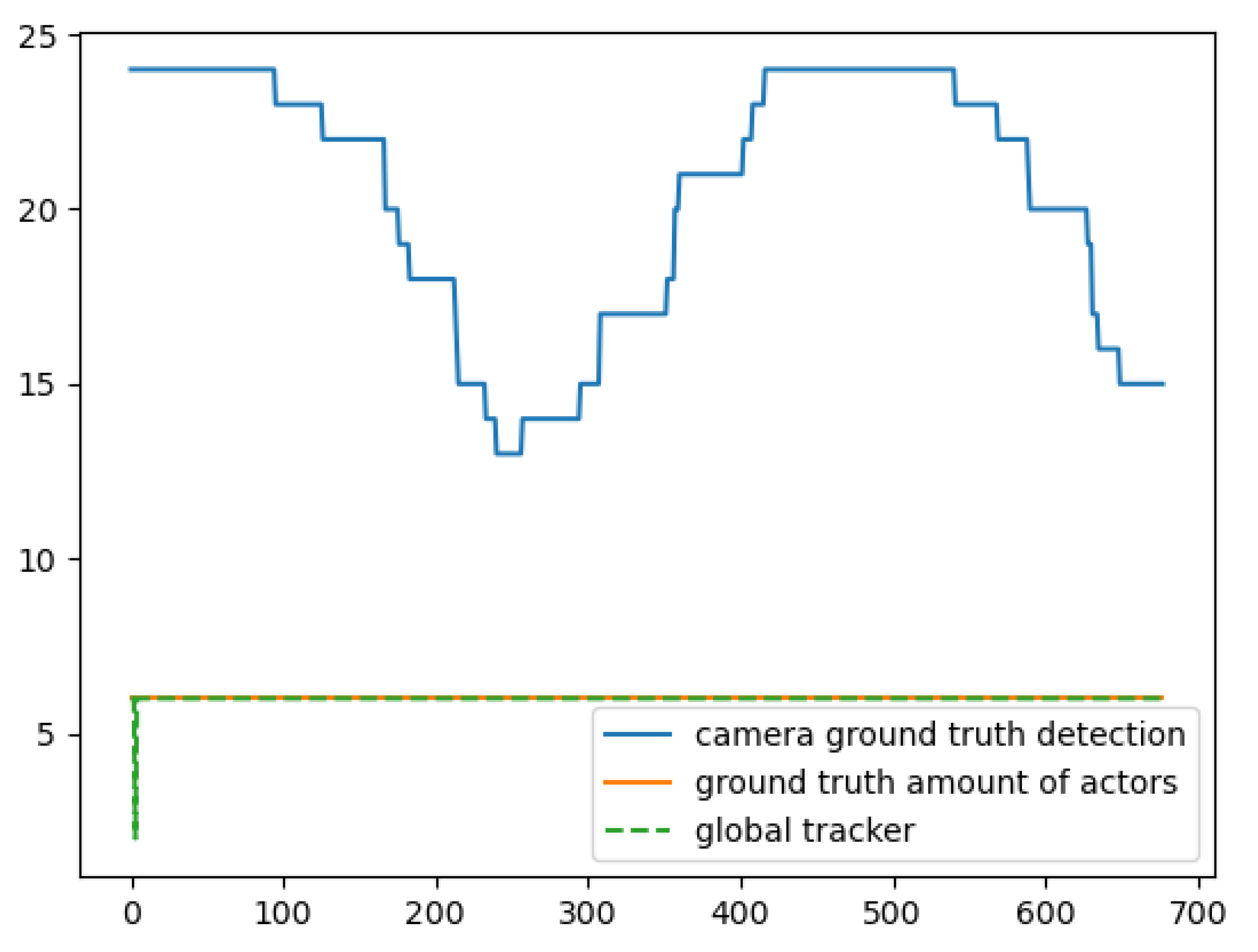
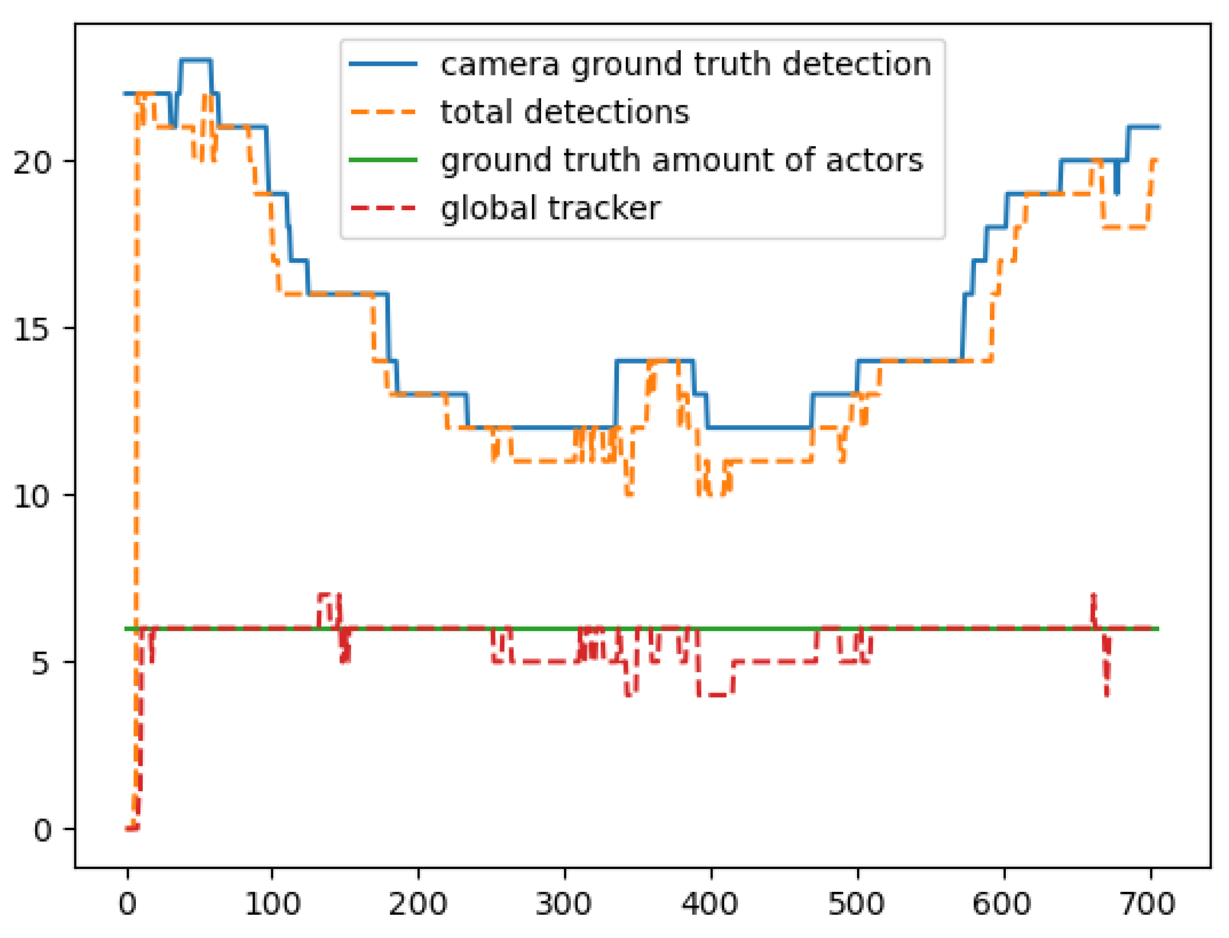
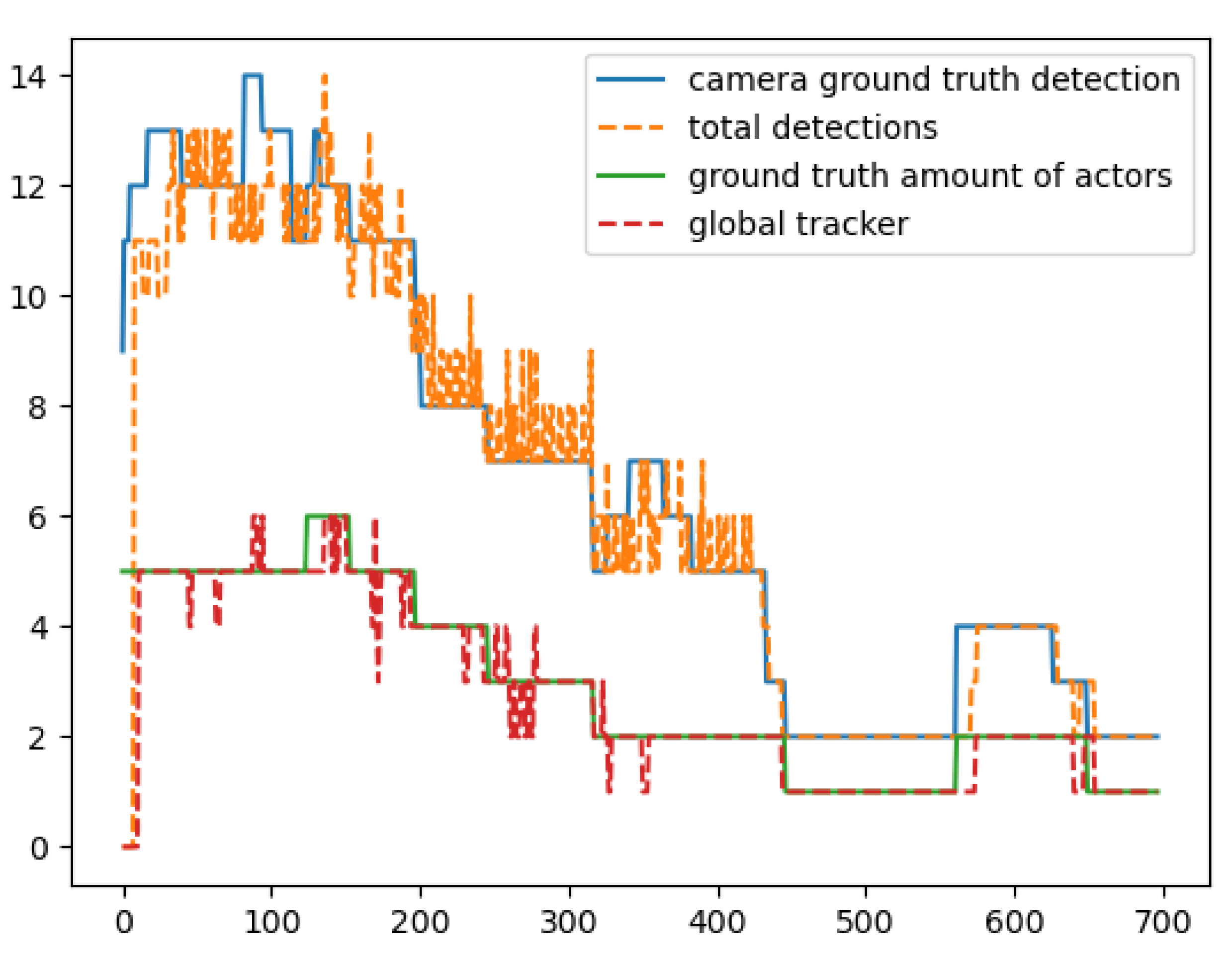
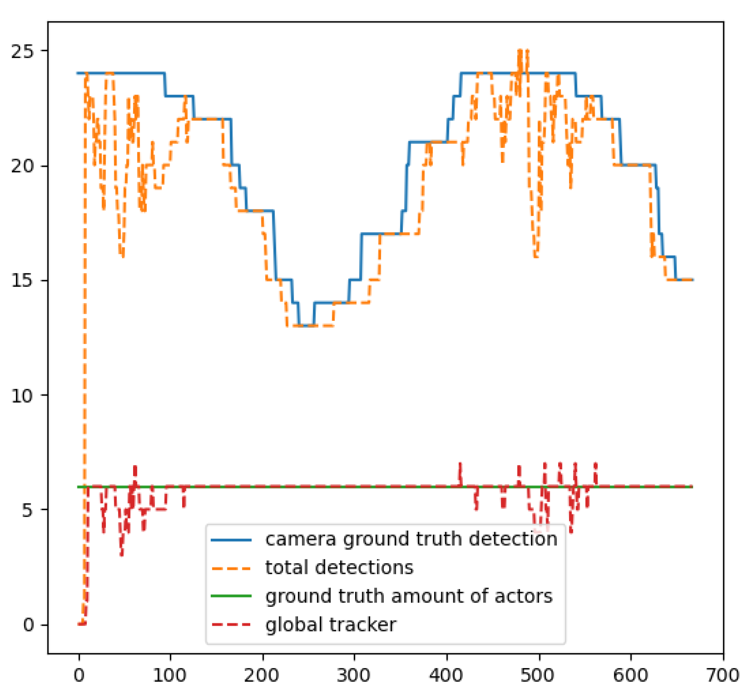
Figure 25, the red line presents the outcome of the global tracker regarding the number of actors detected, the green line presents the total detections in the scenario in every timestep (the sum of detection of all four cameras), the orange line presents the ground truth tracks of the objects, and the blue line the total detections if all cameras could see all the objects. The horizontal axis represents the iterations of the system operated in that scenario.
In
Figure 22, we see the results of the cross-path scenario. In this scenario, the actors move towards the centre of the rectangular area and then back again to their original positions with measurements with no localization error, having crossed paths on several occasions with 3 and more actors participating in the occlusion, hence some cameras are seeing fewer actors than the actual number present in the field of view. When n localisation error exists, the proposed global tracker performs nominally with its results coinciding with the global truth.
It is clear from
Figure 21 and
Figure 22 that the global tracker system is performing perfectly when the input contains perfect observations regarding the localization error despite having cases where all cameras detect all actors.
In
Figure 23, we see the results of the Straight Line scenario. In this scenario, the actors were placed in a straight-line formation and moved in the rectangular area defined by the cameras. The results indicate that in this scenario the global tracker performed exceptionally having a 96.9% of correct calculations in all the frames of this scenario.
In
Figure 24, we see the results of the Random scenario. In this scenario, the actors were making random movements in the rectangular area, having crossed paths on several occasions. The results indicate that in this scenario the global tracker performed exceptionally having 71% of correct calculations in all the frames of this scenario. We can observe that the error pattern of the global tracker matches the error pattern of the total detections. This means that the total detections were underestimating the total number of actors and hence the global tracker was getting an underestimated input and created a similar pattern to its output.
In
Figure 25, we see the results of the Random Pitch scenario. In this scenario, the actors were making random movements in the rectangular area, having crossed paths on several occasions but the camera pitch, in this case, was 25 degrees. The results indicate that in that scenario the global tracker performed exceptionally having 84.6% of correct calculations in all the frames of this scenario.
In
Figure 26, we see the results of the cross-path scenario. In this scenario, the actors move towards the centre of the rectangular area and then back again to their original positions, having crossed paths on several occasions with three and more actors participating in the occlusion. The results indicate that in that scenario the global tracker performed really well, in a scenario where there were too many occlusions having 82.7% of correct calculations in all the frames of this scenario.
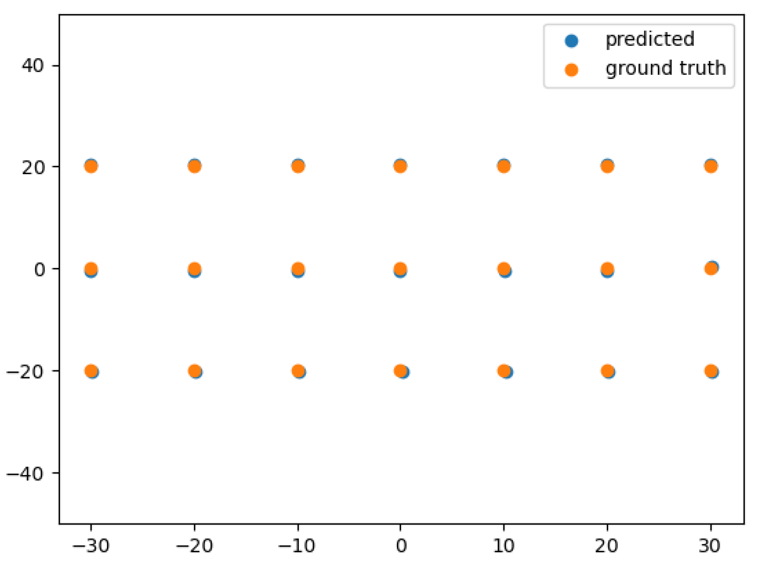
In
Figure 27, we see the results of the static objects moving cameras scenario. In this scenario, the actors remain static and the drones are moving aiming to detect the total number of actors in the area. The blue circles represent the predictions of the global tracker regarding the positions of the actors and the orange ones the actual location of the actors. The results indicate that in that scenario the global tracker performed really well, managing to distinguish correctly the observation and provide accurate results regarding the location of the actors.
We can observe that in all scenarios, the misdetection of the number of actors by the global tracker is caused either by a lack of detections in that case (maybe occlusion) or some few outliers in our dataset based on the way we created the ground truth for our scenarios.
5. Discussion
In this paper, we present a system with a group of UAVs equipped with cameras capable of detecting and tracking multiple objects alongside localizing the detected objects. Furthermore, a global tracker algorithm utilizing information from object detection, and localization is proposed.
The object localization method’s performance is proven to be efficient to be used for additional target tracking and mapping applications. Nevertheless, there are certain things affecting the performance like object detection bounding box accuracy in respect of its size, and the placement orientation of the camera in the drones. An accountable error in the size of the bounding box affects the position used in the algorithm. In an image, a pixel point that is close to the centre of the image is considered to be close, despite a pixel that is located away from the centre being considered to be located further away. Furthermore, if the camera is pitched in opposite to the top-down view, objects detected at large distances are slightly distorted causing an increase in the localization error.
Similar to the object localization method, the predicted bounding box accuracy is crucial to the proposed guidance method, since it uses the centre point of the bounding box to calculate the velocities and desired yaw commands to be used, and it can result in losing track of the desired object.
The global tracker algorithm is proven to depend on the quality of the object detection algorithm regarding the size of the predicted bounding box since the accuracy of the localization algorithm is highly affected, and the ability of the object detection algorithm to provide a few amounts of false positives or false negatives. A meaningful way to evaluate the global tracker algorithm is by comparing in every timestep the actual number of the objects in the world with the estimated objects provided by the algorithm. The results have shown that in this case, in all scenarios the algorithm performs exceptionally and in almost all cases where the objects are distinguishable, it manages to perform perfectly. Some outliers in the scenarios were found regarding the predicted detections and the ground truth. An example is that there were cases where in a frame a small percentage of an actor appears, and still the object detection algorithm manages to detect it but this specific actor was not in the annotations. Regarding the ability of the global tracker to keep the tracking id of the detected objects in all the frames the object participates in, it is proven that if the localization error is small, i.e., less than 0.5 m then the algorithm can keep the id even when multiple occlusions occur when the localization error exceeds that threshold then when an occlusion occur regarding of the overlap there might happen identity switch. Another reason causing identity switches is the transition between cameras when selecting the camera closest to the detected object.
6. Conclusions
In this paper, we present a system with a group of UAVs equipped with cameras capable of detecting and tracking multiple objects alongside localizing the detected objects, and a system to perform global tracking of people in an area using information from different cameras.
Regarding the multiple object detection system, we used and tested four algorithms, YOLOv4, YOLOv4-Tiny, a custom tiny YOLOv4 with three scales as the output and YOLOv7-Tiny in a custom dataset. The results indicate that the custom network implementation can outperform the YOLOv4-Tiny, with recall 0.944, precision 0.998, and mAP 94.36% while its results seem to be similar to the results of YOLOv4. Using three scales in the custom YOLOv4 improved the accuracy of the metrics to the YOLOv4-Tiny. Similarly, in object tracking, the custom YOLOv4 outperforms the other two networks in all the tracking metrics having MOTA 88.2, MOTP 93.3, and MOTAL 88.3 while counting the same identity switches. All the models were outperformed by the YOLOv7-Tiny in all metrics both in detection and tracking. YOLOv7-Tiny achieved a recall of 0.981 and precision of 0.997, and mAP 98.04, while in tracking metrics it had a MOTA of 95.7, an MOTP of 94.7, and a MOTAL of 95.9 proving that indeed it can provide better results with a reduction of parameters in the range of 40%.
Furthermore, the object localization method’s performance is high enough for it to be used for additional target tracking and mapping applications having a mean squared error of 0.205 m. The guidance algorithm for the drones is capable of tracking an object with great accuracy while maintaining the desired constant distance from it and keeping the object in the centre of the camera frame. Regarding the real world tests we performed, we proved that the object detection and tracking system, and the guidance system can be in real-world scenarios and be as efficient as in the simulations.
The global tracker algorithm proved to perform with high-efficiency counting and tracking of the detected objects in an area from different cameras as shown by the results in all scenarios. In particular, in random and straight-line scenarios the global tracker manages to distinguish the objects in 71 and 96.9% of frames, respectively, and similarly and most importantly in the most difficult scenario with multiple cross paths and occlusions the global tracker achieved to distinguish the objects in 82.7% of frames.
Our future work will focus on improving the identity switches occurring in scenarios with a lot of occlusions by using DeepSORT instead of SORT and using features from the detected bounding boxes of every multiple object detection module. Another element of our future work is to fully utilize our system in real-world scenarios.
To conclude, the presented work is a fully applicable system to many domains capable of providing object detection, tracking, localization services, and global tracking utilities, using optical camera-equipped UAVs.
Author Contributions
Conceptualization, I.D., D.M., N.P., V.L. and V.K. (Vassilios Kostopoulos), V.K. (Vaggelis Kapoulas); methodology, I.D. and D.M. and N.P.; software, I.D. and D.M.; validation, I.D. and V.L. and V.K. (Vassilios Kostopoulos) and V.K. (Vaggelis Kapoulas); formal analysis, N.P. and I.D.; investigation, I.D. and D.M.; resources, I.D. and V.L.; data curation, I.D. and D.M.; writing—original draft preparation, I.D.; writing—review and editing, I.D., N.P. and V.L.; visualization, D.M., V.K. (Vassilios Kostopoulos); supervision, V.L. and V.K. (Vassilios Kostopoulos); project administration, V.L. and V.K. (Vassilios Kostopoulos); funding acquisition, V.L. and V.K. (Vassilios Kostopoulos). All authors have read and agreed to the published version of the manuscript.
Funding
This research is based upon work supported by the Air Force Office of Scientific Research under award number FA9550-19-1-7032 (Real-time Decision Making for Autonomous Systems using AI Methods).
Data Availability Statement
Not applicable.
Conflicts of Interest
The authors declare no conflict of interest. The funders had no role in the design of the study; in the collection, analyses, or interpretation of data; in the writing of the manuscript; or in the decision to publish the results.
References
- Daramouskas, I.; Patrinopoulou, N.; Meimetis, D.; Lappas, V.; Kostopoulos, V. A design and simulation of a target detection, tracking and localisation system for UAVs. In Proceedings of the 2022 30th Mediterranean Conference on Control and Automation (MED), Vouliagmeni, Greece, 28 June–1 July 2022; pp. 382–388. [Google Scholar] [CrossRef]
- Khurana, P.; Sharma, A.; Singh, S.N.; Singh, P.K. A survey on object recognition and segmentation techniques. In Proceedings of the 3rd International Conference on Computing for Sustainable Global Development (INDIACom), New Delhi, India, 16–18 March 2016. [Google Scholar]
- Wang, L.; Shi, J.; Song, G.; Shen, I.F. Object detection combining recognition and segmenation. In Proceedings of the 8th Asian Conference on Computer Vision–ACCV 2007, Tokyo, Japan, 18–22 November 2007; Volume 4843, pp. 1258–1276. [Google Scholar]
- Meera, M.K.; Mohan, S.B. Object recognition in images. In Proceedings of the 2016 International Conference on Information Science (ICIS), Kochi, India, 12–13 August 2016. [Google Scholar]
- Sanchez-Matilla, R.; Poiesi, F.; Cavallaro, A. Online Multi-target Tracking with Strong and Weak Detections. In Computer Vision—ECCV 2016 Workshops. ECCV 2016. Lecture Notes in Computer Science; Springer: Cham, Switzerland, 2016. [Google Scholar]
- Bewley, A.; Ge, Z.; Ott, L.; Ramos, F.; Upcroft, B. Simple online and realtime tracking. In Proceedings of the 2016 IEEE International Conference on Image Processing (ICIP), Phoenix, AZ, USA, 25–28 September 2016. [Google Scholar]
- Chu, P.; Ling, H. FAMNet: Joint Learning of Feature, Affinity and Multi-dimensional Assignment for Online Multiple Object Tracking. In Proceedings of the IEEE/CVF International Conference on Computer Vision, Seoul, Republic of Korea, 27 October–2 November 2019. [Google Scholar]
- Jung, H.K.; Choi, G.S. Improved YOLOv5: Efficient Object Detection Using Drone Images under Various Conditions. Appl. Sci. 2022, 12, 7255. [Google Scholar] [CrossRef]
- Baidya, R.; Jeong, H. YOLOv5 with ConvMixer Prediction Heads for Precise Object Detection in Drone Imagery. Sensors 2022, 22, 8424. [Google Scholar] [CrossRef] [PubMed]
- Gupta, H.; Verma, O.P. Monitoring and surveillance of urban road traffic using low altitude drone images: A deep learning approach. Multimed. Tools Appl. 2022, 81, 19683–19703. [Google Scholar] [CrossRef]
- Kim, I.; Yow, K.C. Object Location Estimation from a Single Flying Camera. 2015. Available online: https://www.thinkmind.org/articles/ubicomm_2015_5_10_10080.pdf (accessed on 15 December 2022).
- Sanyal, S.; Bhushan, S.; Sivayazi, K. Detection and Location Estimation of Object in Unmanned Aerial Vehicle using Single Camera and GPS. In Proceedings of the 2020 First International Conference on Power, Control and Computing Technologies (ICPC2T), Raipur, India, 3–5 January 2020; pp. 73–78. [Google Scholar] [CrossRef]
- Yow, K.C.; Kim, I. General Moving Object Localization from a Single Flying Camera. Appl. Sci. 2020, 10, 6945. [Google Scholar] [CrossRef]
- Meimetis, D.; Daramouskas, I.; Perikos, I.; Hatzilygeroudis, I. Real-time multiple object tracking using deep learning methods. Neural Comput. Appl. 2021, 35, 89–118. [Google Scholar] [CrossRef]
- Wang, C.Y.; Bochkovskiy, A.; Liao, H.Y.M. YOLOv7: Trainable bag-of-freebies sets new state-of-the-art for real-time object detectors. arXiv 2022, arXiv:2207.02696. [Google Scholar]
- Bochkovskiy, A.; Wang, C.Y.; Liao, H.Y.M. YOLOv4: Optimal Speed and Accuracy of Object Detection. arXiv 2020, arXiv:2004.10934. [Google Scholar]
- Chollet, F. Keras. 2015. Available online: https://keras.io (accessed on 14 December 2022).
- Paszke, A.; Gross, S.; Massa, F.; Lerer, A.; Bradbury, J.; Chanan, G.; Killeen, T.; Lin, Z.; Gimelshein, N.; Antiga, L.; et al. PyTorch: An Imperative Style, High-Performance Deep Learning Library. In Advances in Neural Information Processing Systems 32; Curran Associates, Inc.: Red Hook, NY, USA, 2019; pp. 8024–8035. [Google Scholar]
- Wojke, N.; Bewley, A.; Paulus, D. Simple Online and Realtime Tracking with a Deep Association Metric. In Proceedings of the 2017 IEEE International Conference on Image Processing (ICIP), Beijing, China, 17–20 September 2017. [Google Scholar]
- Bernardin, K.; Stiefelhagen, R. Evaluating multiple object tracking performance: The CLEAR MOT metrics. EURASIP J. Image Video Process. 2008, 2008, 246309. [Google Scholar] [CrossRef] [Green Version]
- Quigley, M.; Gerkey, B.; Conley, K.; Faust, J.; Foote, T.; Leibs, J.; Berger, E.; Wheeler, R.; Ng, A. ROS: An open-source Robot Operating System. In Proceedings of the IEEE/RSJ International Conference on Intelligent Robots and Systems, Sendai, Japan, 28 September–2 October 2004. [Google Scholar]
- Koenig, N.; Howard, A. Design and use paradigms for Gazebo, an open-source multi-robot simulator. In Proceedings of the IEEE/RSJ International Conference on Intelligent Robots and Systems, Sendai, Japan, 28 September–2 October 2004. [Google Scholar]
- Meier, L.; Honegger, D.; Pollefeys, M. PX4: A node-based multithreaded open source robotics framework for deeply embedded platforms. In Proceedings of the IEEE International Conference on Robotics and Automation (ICRA), Seattle, WA, USA, 26–30 May 2015. [Google Scholar]
- Redmon, J. Darknet: Open Source Neural Networks in C. 2013–2016. Available online: http://pjreddie.com/darknet/ (accessed on 12 February 2023).
- Ghorpade, J.; Parande, J.; Kulkarni, M.; Bawaskar, A. GPGPU Processing in CUDA Architecture. arXiv 2012, arXiv:1202.4347. [Google Scholar] [CrossRef]
- Abadi, M.; Agarwal, A.; Barham, P.; Brevdo, E.; Chen, Z.; Citro, C.; Corrado, G.S.; Davis, A.; Dean, J.; Devin, M.; et al. TensorFlow: Large-Scale Machine Learning on Heterogeneous Systems. 2015. Available online: http://tensorflow.org (accessed on 14 December 2022).
- Zhu, P.; Wen, L.; Du, D.; Bian, X.; Fan, H.; Hu, Q.; Ling, H. Detection and Tracking Meet Drones Challenge. IEEE Trans. Pattern Anal. Mach. Intell. 2022, 44, 7380–7399. [Google Scholar] [CrossRef] [PubMed]
- Dendorfer, P.; Rezatofighi, H.; Milan, A.; Shi, J.; Cremers, D.; Reid, I.; Roth, S.; Schindler, K.; Leal-Taixé, L. MOT20: A benchmark for multi object tracking in crowded scenes. arXiv 2020, arXiv:2003.09003. [Google Scholar]
Figure 1.
Flow chart presenting an overview of the localization and tracking system’s architecture.
Figure 1.
Flow chart presenting an overview of the localization and tracking system’s architecture.
Figure 2.
Flow chart presenting an overview of the system’s architecture for the global tracker.
Figure 2.
Flow chart presenting an overview of the system’s architecture for the global tracker.
Figure 3.
Example images from the training dataset.
Figure 3.
Example images from the training dataset.
Figure 4.
Flow chart of the training process of custom YOLOv4.
Figure 4.
Flow chart of the training process of custom YOLOv4.
Figure 5.
Images from test dataset.
Figure 5.
Images from test dataset.
Figure 6.
The detection results of the custom YOLO.
Figure 6.
The detection results of the custom YOLO.
Figure 7.
ROC Curve for YOLOv4 custom.
Figure 7.
ROC Curve for YOLOv4 custom.
Figure 8.
ROC Curve for YOLOv7-Tiny.
Figure 8.
ROC Curve for YOLOv7-Tiny.
Figure 9.
ROC Curve for YOLOv4-Tiny.
Figure 9.
ROC Curve for YOLOv4-Tiny.
Figure 10.
ROC Curve for YOLOv4-608.
Figure 10.
ROC Curve for YOLOv4-608.
Figure 11.
Image from the “rural road” video.
Figure 11.
Image from the “rural road” video.
Figure 12.
Image mot-20 video.
Figure 12.
Image mot-20 video.
Figure 13.
Deviation of the localization estimations from the ground truth.
Figure 13.
Deviation of the localization estimations from the ground truth.
Figure 14.
Initial detection and approach.
Figure 14.
Initial detection and approach.
Figure 15.
Target following over time.
Figure 15.
Target following over time.
Figure 16.
Real world target following over time.
Figure 16.
Real world target following over time.
Figure 17.
Real world target following over time.
Figure 17.
Real world target following over time.
Figure 18.
Image of the real world scenario for guidance.
Figure 18.
Image of the real world scenario for guidance.
Figure 19.
Computational time performance with one drone.
Figure 19.
Computational time performance with one drone.
Figure 20.
Computational time performance with four drones.
Figure 20.
Computational time performance with four drones.
Figure 21.
Instances from different timesteps.
Figure 21.
Instances from different timesteps.
Figure 22.
Graph showing the global tracker results in comparison to the ground truth for the Cross Path with no localization error scenario. The vertical axis represents the number of actors, while the horizontal axis the frames.
Figure 22.
Graph showing the global tracker results in comparison to the ground truth for the Cross Path with no localization error scenario. The vertical axis represents the number of actors, while the horizontal axis the frames.
Figure 23.
Graph showing the global tracker results in comparison to the ground truth for the Straight Line scenario. The vertical axis represents the number of actors, while the horizontal axis the frames.
Figure 23.
Graph showing the global tracker results in comparison to the ground truth for the Straight Line scenario. The vertical axis represents the number of actors, while the horizontal axis the frames.
Figure 24.
Graph showing the global tracker results in comparison to the ground truth for the random movement scenario. The vertical axis represents the number of actors, while the horizontal axis the frames.
Figure 24.
Graph showing the global tracker results in comparison to the ground truth for the random movement scenario. The vertical axis represents the number of actors, while the horizontal axis the frames.
Figure 25.
Graph showing the global tracker results in comparison to the ground truth for the random movement with pitched camera scenario. The vertical axis represents the number of actors, while the horizontal axis the frames.
Figure 25.
Graph showing the global tracker results in comparison to the ground truth for the random movement with pitched camera scenario. The vertical axis represents the number of actors, while the horizontal axis the frames.
Figure 26.
Graph showing the global tracker results in comparison to the ground truth for the cross path scenario. The vertical axis represents the number of actors, while the horizontal axis the frames.
Figure 26.
Graph showing the global tracker results in comparison to the ground truth for the cross path scenario. The vertical axis represents the number of actors, while the horizontal axis the frames.
Figure 27.
Graph showing the global tracker results in comparison to the ground truth for the static objects moving cameras scenario. The vertical axis represents the number of actors, while the horizontal axis the frames.
Figure 27.
Graph showing the global tracker results in comparison to the ground truth for the static objects moving cameras scenario. The vertical axis represents the number of actors, while the horizontal axis the frames.
Table 1.
Custom YOLO training parameters.
Table 1.
Custom YOLO training parameters.
| Epochs | Steps | Optimizer | LR | Callbacks |
|---|
| 5000 | 20 | Adam | 0.001 | Reduce LR |
| | | | | Monitor |
| | | | | Early stopping |
Table 2.
Detection metrics.
Table 2.
Detection metrics.
| Metric | YOLO-Tiny | YOLO-608 | YOLO-Custom | YOLOv7-Tiny |
|---|
| Total Positives | 4186 | 4186 | 4186 | 4186 |
| True Positives | 3713 | 4011 | 3953 | 4108 |
| False Positives | 36 | 30 | 7 | 11 |
| Recall | 0.887 | 0.958 | 0.944 | 0.981 |
| Precision | 0.99 | 0.992 | 0.998 | 0.997 |
| F1-Score | 0.935 | 0.975 | 0.97 | 0.989 |
| Average Precision | 88.07% | 95.36% | 94.36% | 98.04% |
Table 3.
Simulation results for tracking.
Table 3.
Simulation results for tracking.
| Metric | YOLO-Tiny | YOLO-608 | YOLO-Custom | YOLOv7-Tiny |
|---|
| IDs | 6 | 5 | 5 | 6 |
| MOTA | 69.9 | 69.9 | 88.2 | 95.7 |
| MOTP | 90.1 | 90.1 | 93.3 | 94.7 |
| MOTAL | 70 | 70 | 88.3 | 95.9 |
Table 4.
Real-world example for tracking.
Table 4.
Real-world example for tracking.
| Metric | MOT20-01 | Rural Road |
|---|
| IDs | 601 | 8 |
| MOTA | 45.6 | 71.0 |
| MOTP | 51.1 | 71.3 |
| MOTAL | 48.6 | 71.5 |
| Disclaimer/Publisher’s Note: The statements, opinions and data contained in all publications are solely those of the individual author(s) and contributor(s) and not of MDPI and/or the editor(s). MDPI and/or the editor(s) disclaim responsibility for any injury to people or property resulting from any ideas, methods, instructions or products referred to in the content. |
© 2023 by the authors. Licensee MDPI, Basel, Switzerland. This article is an open access article distributed under the terms and conditions of the Creative Commons Attribution (CC BY) license (https://creativecommons.org/licenses/by/4.0/).


 ,
, 


