
Substantiating and Implementing Concept of Digital Twins for Virtual Commissioning of Industrial Mechatronic Complexes Exemplified by Rolling Mill Coilers
 ,
,  , ,
, ,  and
and
Abstract
:1. Introduction
- the simulation stage when developing and designing automation equipment and tools,
- the commissioning stage with virtual system generation,
- during operation to reconfigure and monitor technical conditions.
- “DTP is the prototype of the physical artifact. It considers all the data required to reproduce the product physically after determining the prototype in the virtual space.” When using Matlab software, modules of Simulink libraries or Simscape domains can be used as twin prototypes.
- “DTI means a digital representation of a physical product. This requires continuous connections throughout the entire life cycle to optimize the virtual model over time.” In this case, the data flow is directed oppositely to that in DTP, i.e., from the physical product to the digital model. When studying rolling mills, a typical DTI is a strip, the parameters and properties of which change during processing.
2. Problem Formulation
2.1. Alternative VC Options
- Conventional commissioning, when a real mechatronic system and a real programmable logic controller are used to test the control system. The control system is tested after commissioning.
- Reality-In-The-Loop (RIL) most accurately reflects the typical commissioning in the sense that the simulated control system is used to test the physicomechanical system [32]. In this system, commissioning is not possible until the physical system is installed.
- Hardware-In-The-Loop (HIL) uses the real mechanical system’s response simulation model and is controlled by a real controller. The control software can be tested at the early stages by replacing the mechanical system with its virtual version.
- Software-In-The-Loop (SIL) using both a virtual control system and a virtual mechanical one is another step forward. In this case, the simulation speed may be higher or lower than the real one, depending on the test purpose. Several tests can be quickly performed at higher speeds while complex systems can be tested at low ones.
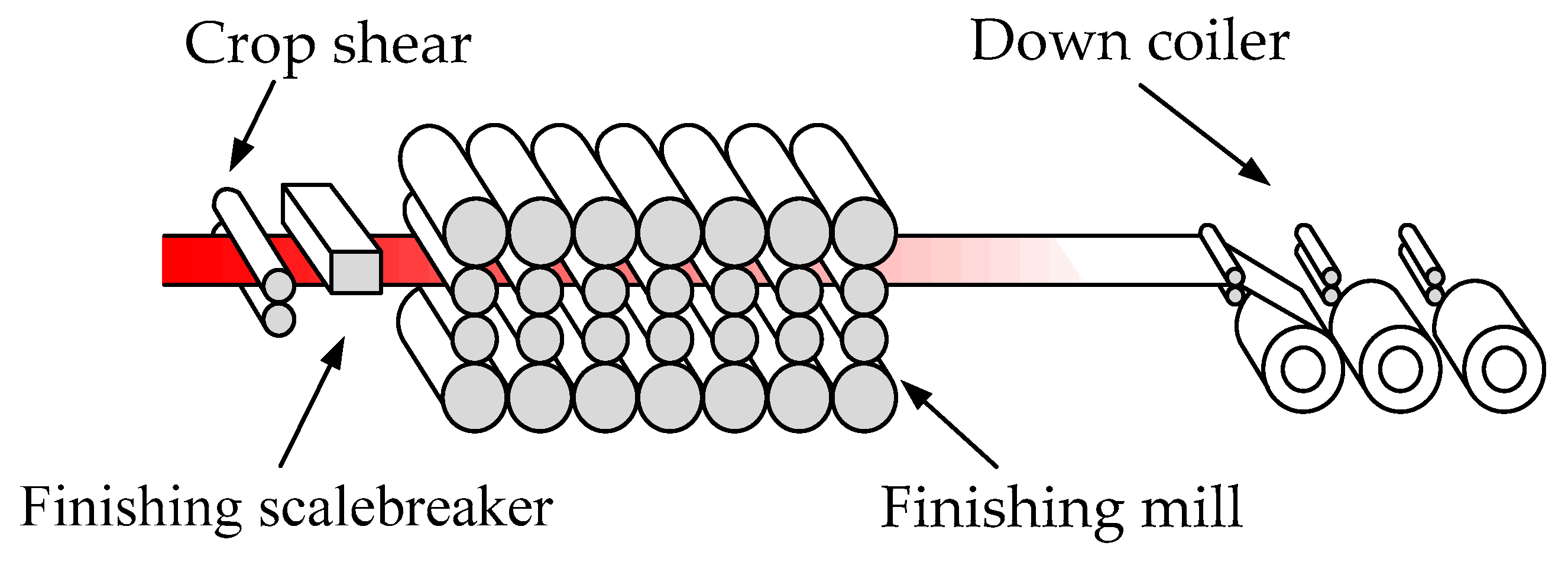
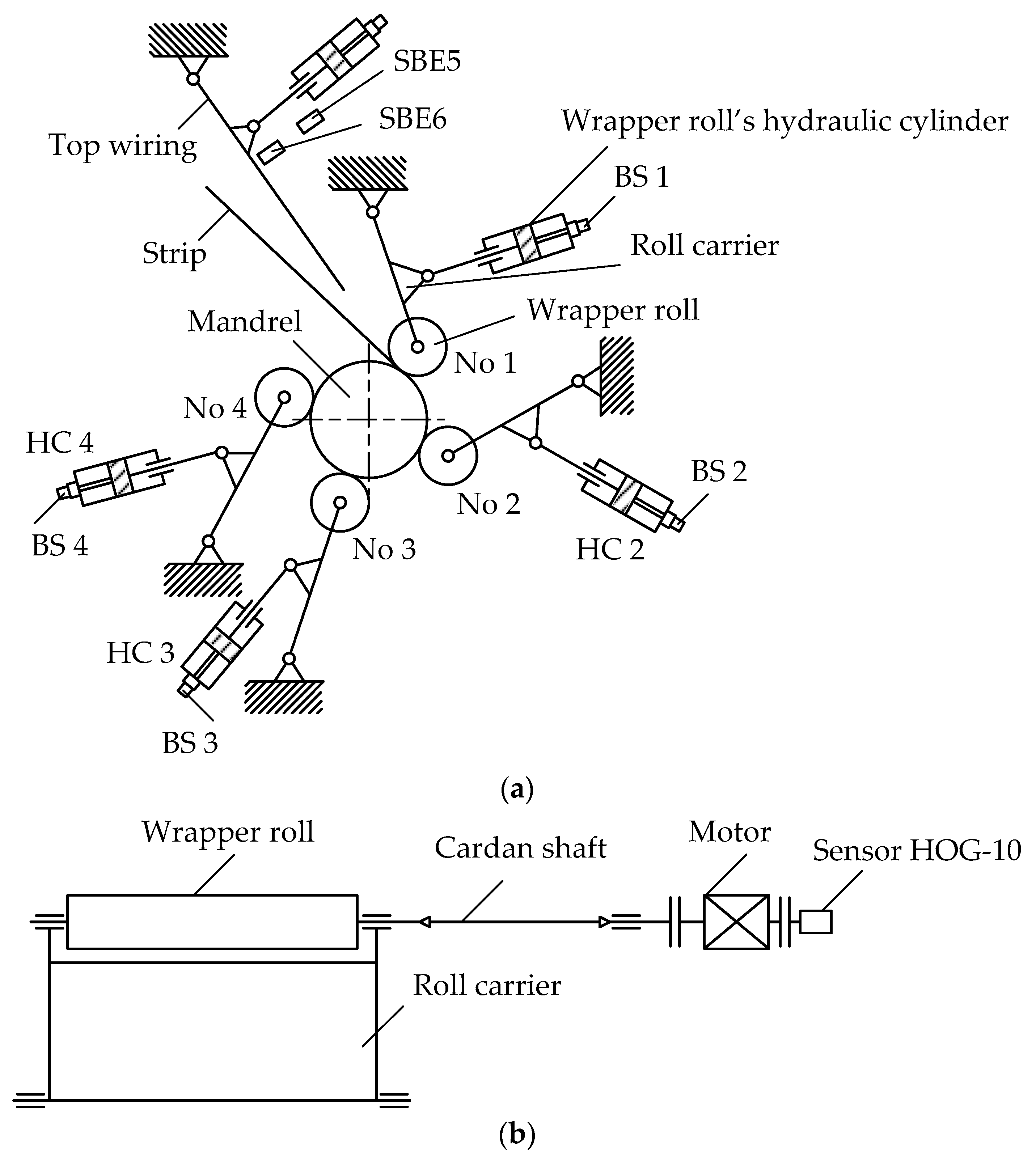
2.2. The Research Object Description
2.3. Justifying the Concept of Object-Oriented DTs of Mechatronic Systems
- developing relatively simple object-oriented digital twins-prototypes of electromechanical and hydraulic systems,
- developing digital twins-instances reflecting all the essential links of the object,
- combining DTP and DTI into an aggregated digital twin of a higher-level mechatronic complex or process facility.
3. Materials and Methods
- In general, they should simulate the operating modes of the unit under study or an individual process unit (rolling stand, coiler, screw-down mechanisms, etc.).
- Parameters and configurations of local systems should correspond to those set for the object investigated.
- All critical links of individual automated systems should be reproduced, in our case—electric and hydraulic drives.
- When developing, a single concept and elemental base of automation systems adopted for a specific unit should be preserved.
- Justifying mathematical dependencies and apparatus, minimally sufficient for reliable simulation of the object in the hardware and software of a PLC or an industrial PC.Note: For the coiler under study, such dependencies have been developed and used during virtual commissioning. They are not described herein due to the significant data volume.
- Developing software to conduct the object simulation in the PLC language or developing a simulator using a specially allocated computer. Developing control algorithms in the PLC language.Note: The coiler group models have been pre-developed for this particular case on a separate PC in the Matlab Simulink software package. Upon developing control algorithms and defining the controller configuration parameters, all the mechatronic complex operating modes were studied on a virtual model.
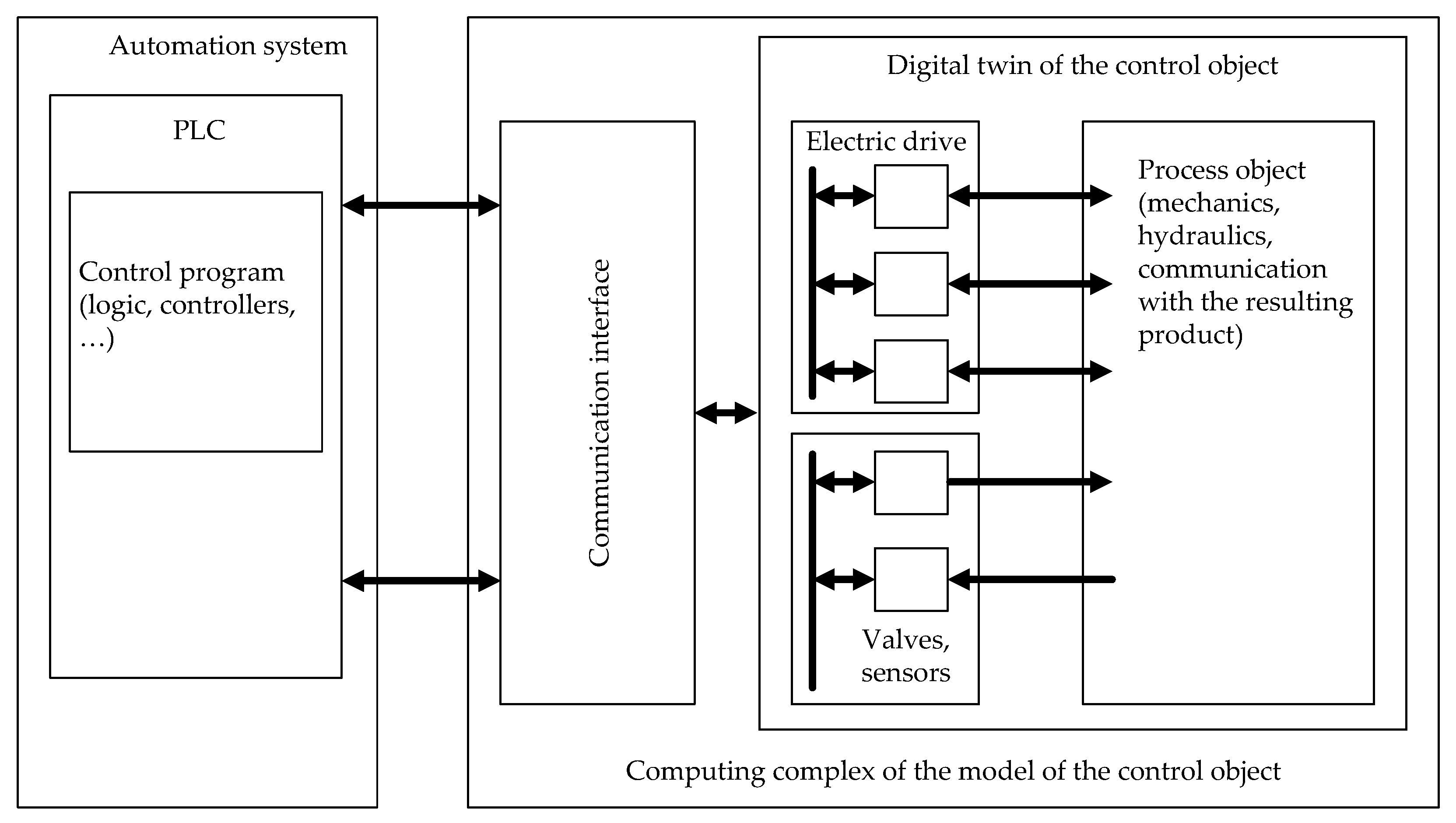
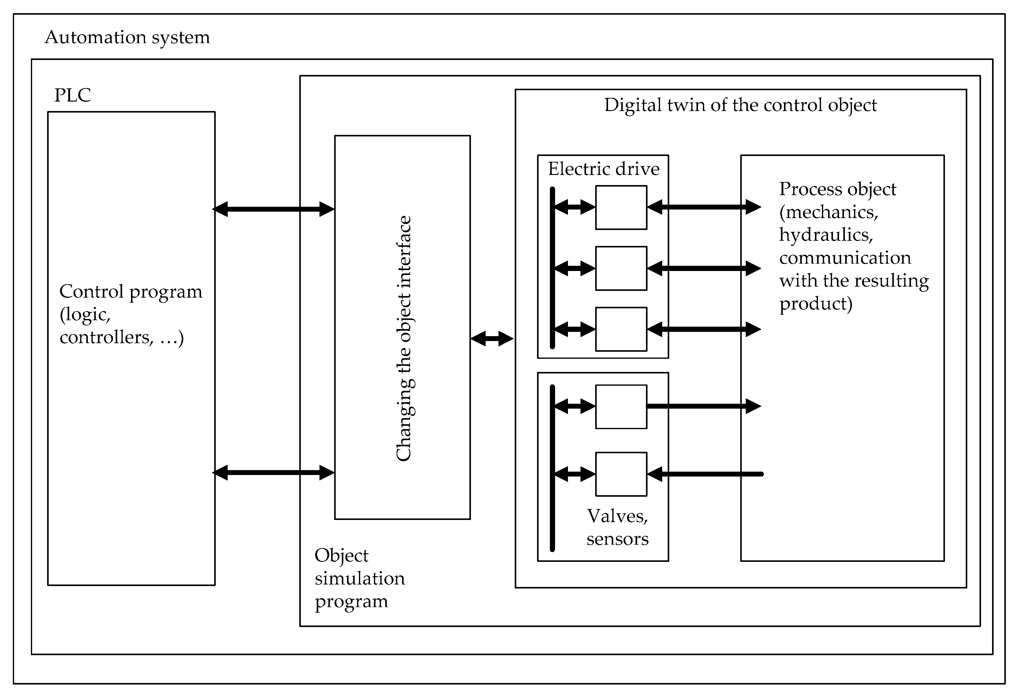
- Building digital twins for commercially available PLCs or in the PLC-PC complex. In this case, the problem of developing or choosing an interface arises.
- Practical implementation on an operating unit.
- Developing (or debugging) ACPS algorithms, visualization tools, and interfaces of industrial digital systems. In particular, this is required when using the developed DTs to monitor conditions after switching the PLC to a regular operation mode.Note: Developing systems for monitoring the technical condition of the equipment is an independent complex problem that cannot be solved as part of virtual commissioning.
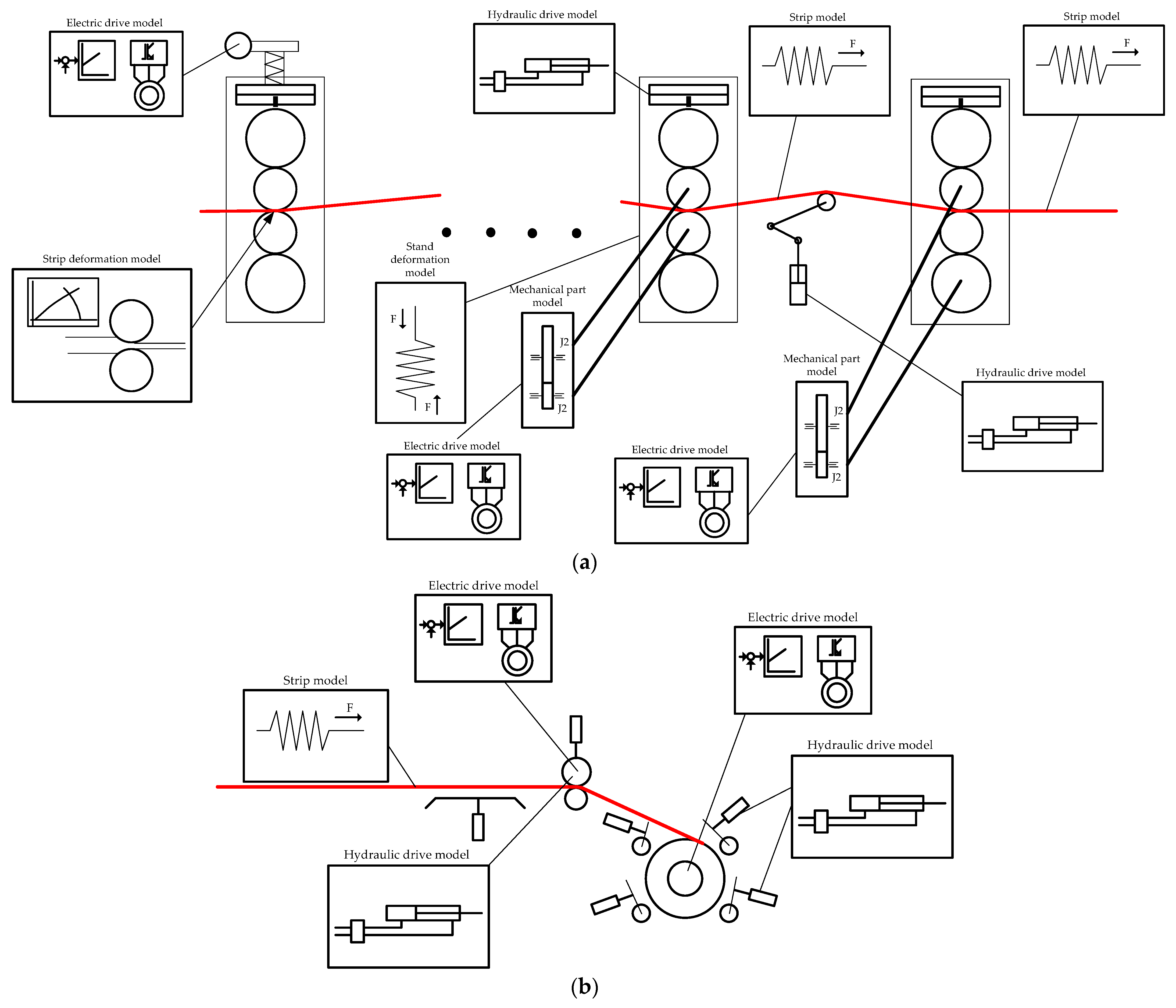
3.1. Modular Construction of DTA of Rolling Mills
- Motion control DT (control panel gives control commands);
- DTPs of the main drives;
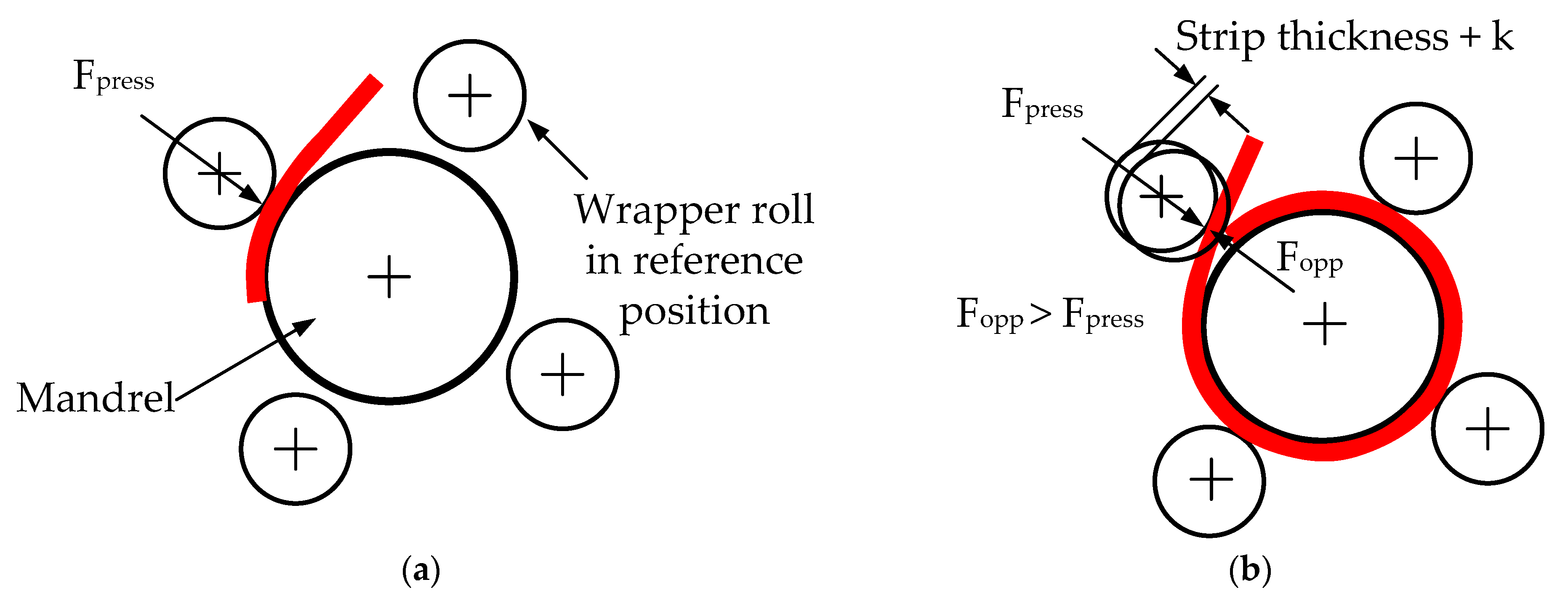
- DTPs of hydraulic units simulating (for the stand):
- –
- deformation zone;
- –
- rolling force;
- DTI of the strip between stands (interlink of stands through the strip);
- DTIs simulating the link between the last stand and driving rollers of the coiler;
- thickness measurement devices (Digital Shadows—DS);
- flatness measuring devices (DS).
- DTA of hydraulic or electromechanical loopers.
3.2. Methodology of Developing DTs for VC
- Upon completing the design stage—developing simulation models and control algorithms, the virtual configuring of the control system. For electrical and mechatronic systems of rolling mills, developing models in the Matlab Simulink software package is optimal. Simscape domains can also be used, in which case a DTE application can be generated.
- Digital twin development. To do this, the model algorithms are implemented on the computing tools of controllers designed to control processes. Model structures and pre-developed control algorithms are “transferred” from the Simulink to the PLC software.
- Direct virtual commissioning. At this stage, control algorithms are debugged, and settings are refined.
- Connecting PLCs with developed control algorithms to a physical object. Experimental research, transfer to pilot operation.
- “Transfer” of the object digital twin to the higher level computer software to use it for the online control over process parameters and technical conditions of equipment.
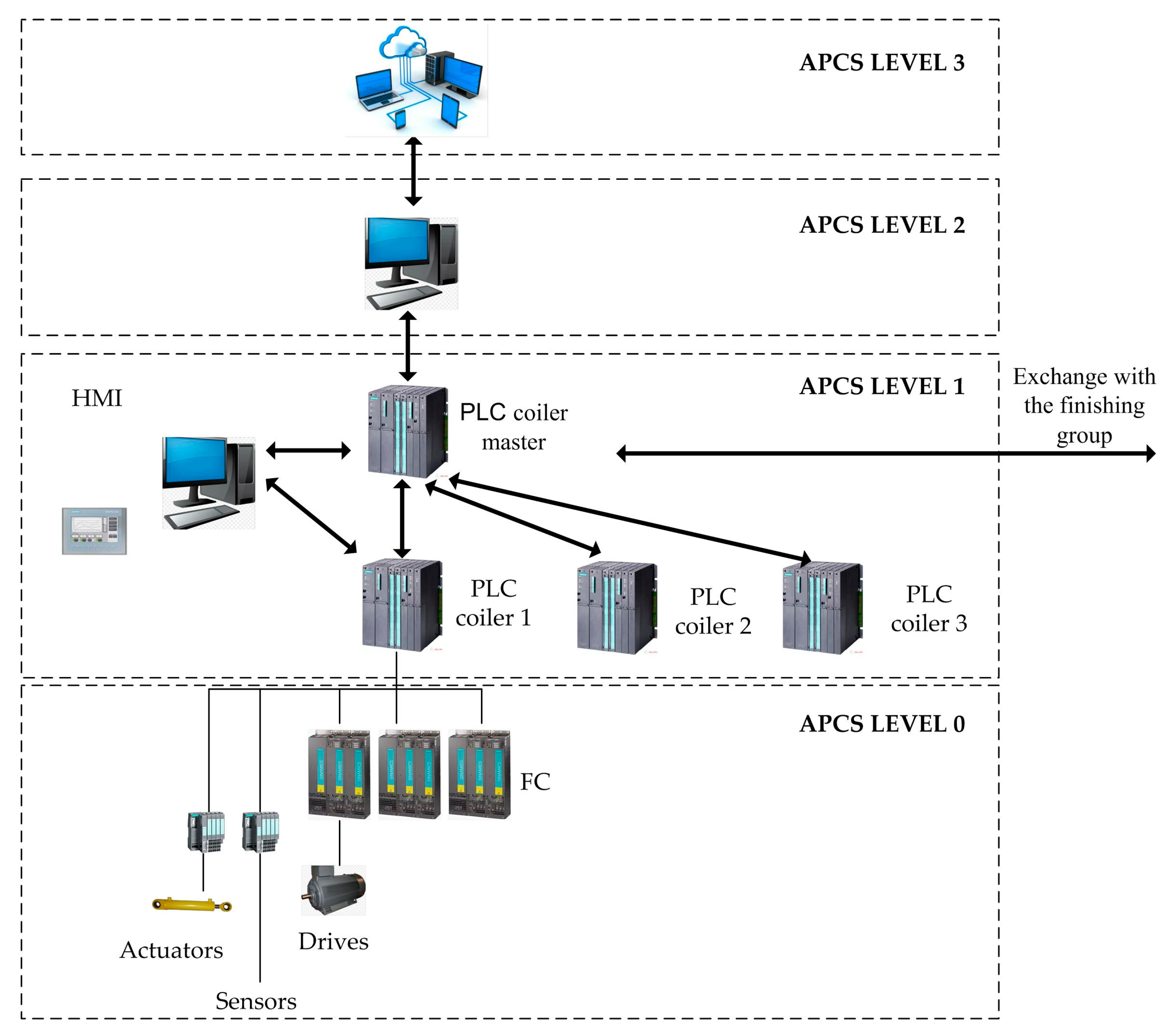
4. Implementation
5. Results
- Soft commissioning: A combination of a hardware PLC and a simulated system (hardware in the HIL cycle),
- The results obtained on the coiler (or group of coilers) after the “physical” commissioning with the control system configured in the HIL mode.
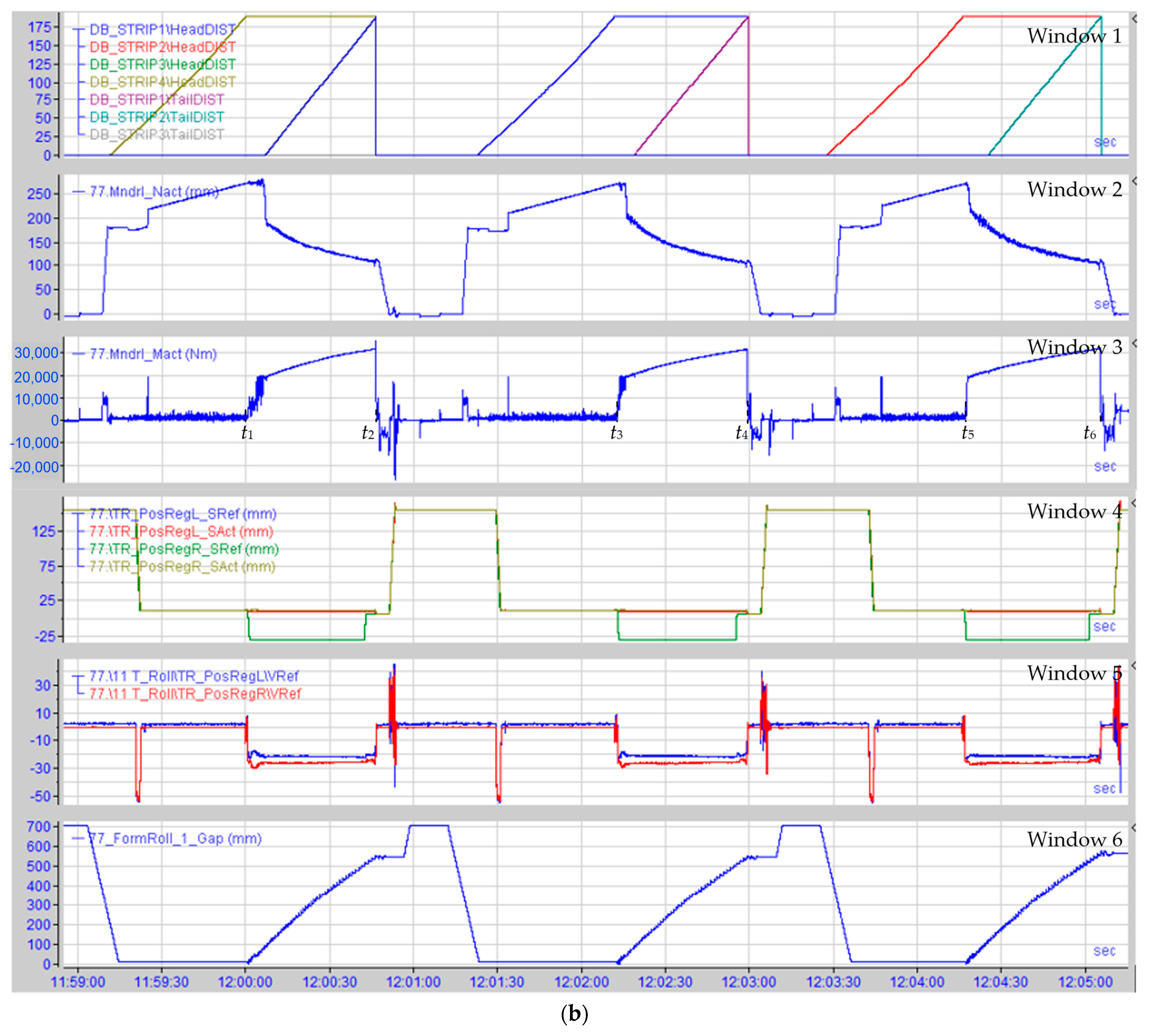
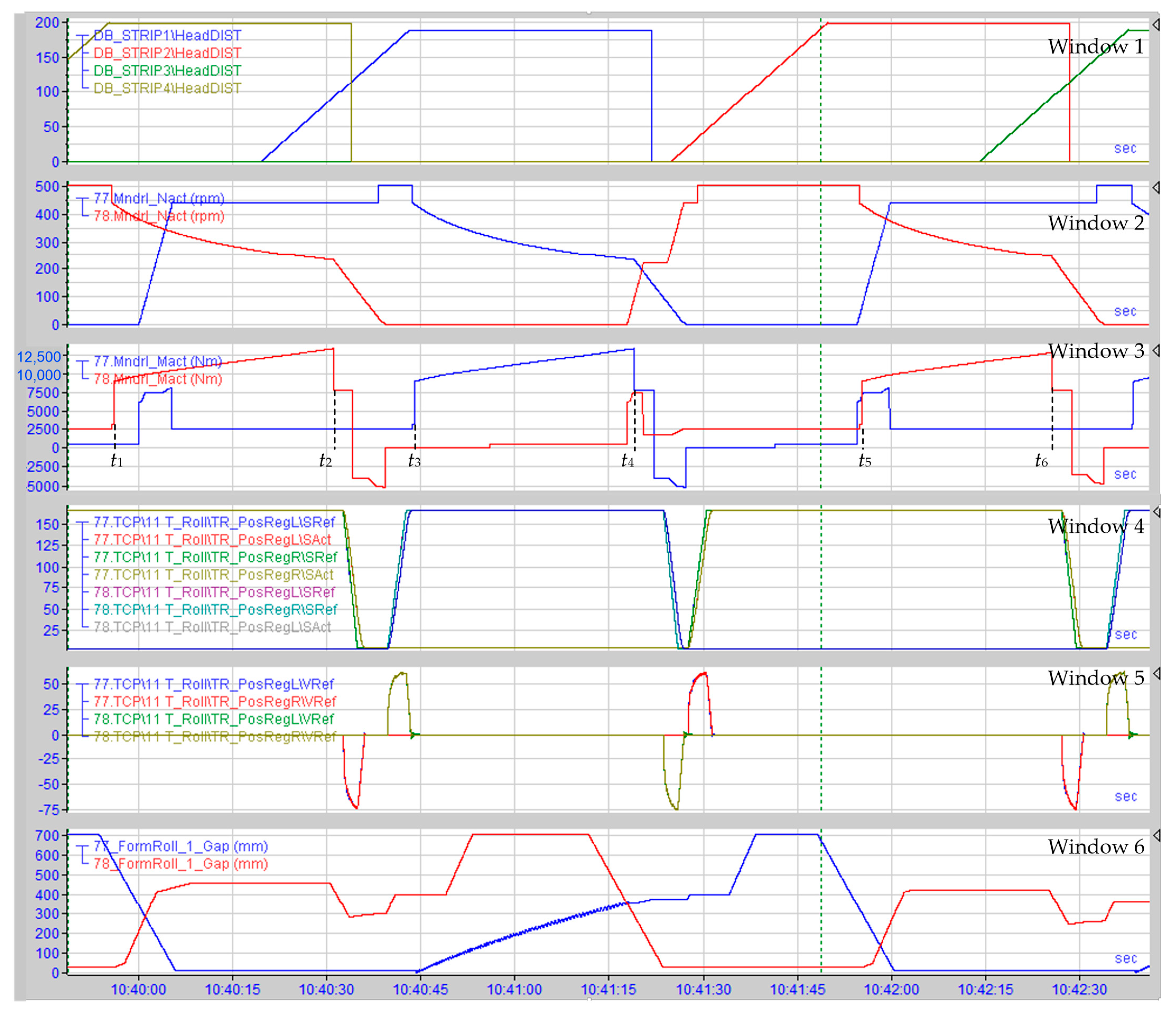
5.1. Experiment
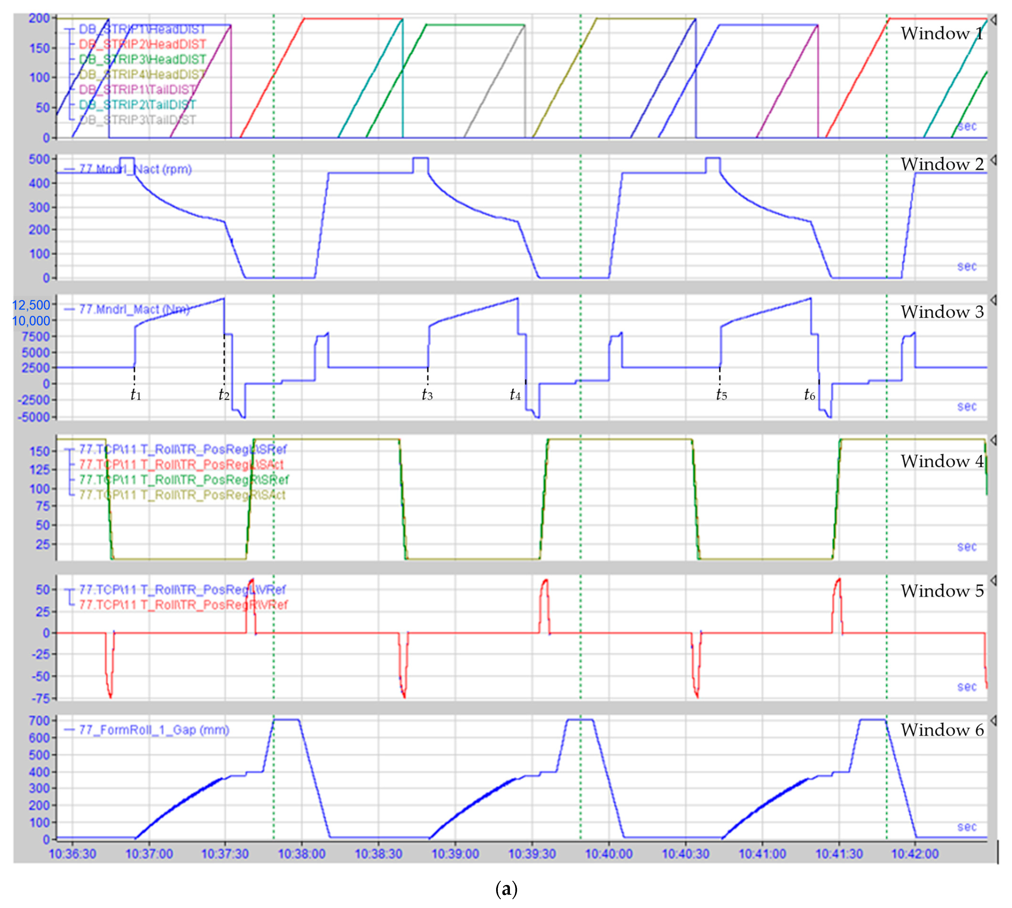
- The HIL and physical configuration results in, respectively, Figure 12a,b are identical. This means that the virtual controller operates similarly to the designed one, and the virtual model is adequate to the object under study. This confirms the digital twin adequacy to a real mechatronic system.
- The analysis of Figure 12 and Figure 13 confirms that the developed aggregated digital twin reliably reflects the processes for both a single coiler and a group of coilers. Therefore, it is suitable to virtually configure a process complex. It may also be implemented at other stages of the unit’s life cycle (except for disposal).
5.2. Virtual Commissioning
5.3. Scientific and Practical Significance of the Results
6. Discussion of the Results
7. Conclusions and Prospects for Future Research
Author Contributions
Funding
Data Availability Statement
Conflicts of Interest
Abbreviations
| APCS | Automatic Process Control System |
| BS | Position Sensors |
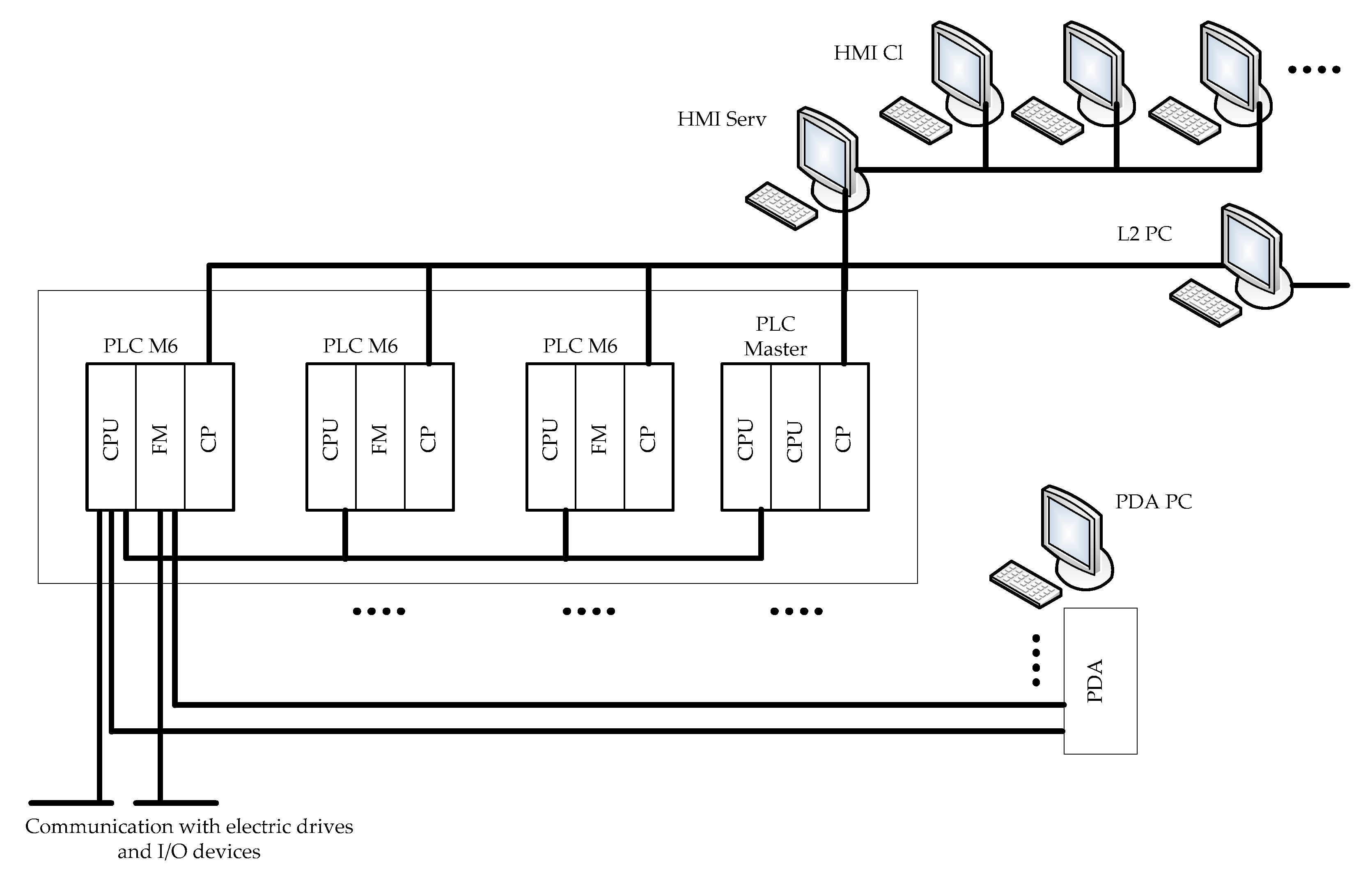
| CP | Communication Processor |
| CPU | Central Processing Unit |
| DT | Digital Twin |
| DTA | Digital Twin Aggregate |
| DTE | Digital Twin Environment |
| DTE | Digital Twin Instance |
| DTP | Digital Twin Prototype |
| DS | Digital Shadows |
| FM | Fast Computing Processor |
| HC | Hydraulic Cylinder |
| HIL | Hardware-In-The-Loop |
| HMI | Human-machine Interface |
| HRM | Hot rolling Mill |
| PC | Personal Computer |
| PDA | Process Data Acquisition |
| PLC | Programmable Logic Controller |
| RIL | Reality-In-The-Loop |
| SIL | Software-In-The-Loop |
| VC | Virtual Commissioning |
| WR | Wrapper Rolls |
References
- Konstantinov, S.; Assad, F.; Ahmad, B.; Vera, D.A.; Harrison, R. Virtual Engineering and Commissioning to Support the Lifecycle of a Manufacturing Assembly System. Machines 2022, 10, 939. [Google Scholar] [CrossRef]
- Tao, F.; Zhang, H.; Liu, A.; Nee, A.Y.C. Digital Twin in Industry: State-of-the-Art. IEEE Trans. Ind. Inform. 2019, 4, 2405–2415. [Google Scholar] [CrossRef]
- Mohammed, W.M.; Haber, R.E.; Martinez Lastra, J.L. Ontology-Driven Guidelines for Architecting Digital Twins in Factory Automation Applications. Machines 2022, 10, 861. [Google Scholar] [CrossRef]
- Bécue, A.; Maia, E.; Feeken, L.; Borchers, P.; Praça, I. A New Concept of Digital Twin Supporting Optimization and Resilience of Factories of the Future. Appl. Sci. 2020, 10, 4482. [Google Scholar] [CrossRef]
- Moiceanu, G.; Paraschiv, G. Digital Twin and Smart Manufacturing in Industries: A Bibliometric Analysis with a Focus on Industry 4.0. Sensors 2022, 22, 1388. [Google Scholar] [CrossRef]
- Jones, D.; Snider, C.; Nassehi, A.; Yon, J.; Hicks, B. Characterising the Digital Twin: A systematic literature review. CIRP J. Manuf. Sci. Technol. 2020, 29, 36–52. [Google Scholar] [CrossRef]
- Choi, S.; Woo, J.; Kim, J.; Lee, J.Y. Digital Twin-Based Integrated Monitoring System: Korean Application Cases. Sensors 2022, 22, 5450. [Google Scholar] [CrossRef] [PubMed]
- Popescu, D.; Dragomir, M.; Popescu, S.; Dragomir, D. Building Better Digital Twins for Production Systems by Incorporating Environmental Related Functions—Literature Analysis and Determining Alternatives. Appl. Sci. 2022, 12, 8657. [Google Scholar] [CrossRef]
- Fuller, A.; Fan, Z.; Day, C.; Barlow, C. Digital Twin: Enabling Technologies, Challenges and Open Research. IEEE Access 2020, 8, 108952–108971. [Google Scholar] [CrossRef]
- Digital Twins and Virtual Commissioning in Industry 4.0. Visual Components 4.3. Available online: https://www.visualcomponents.com/products/visual-components/ (accessed on 10 September 2022).
- Oztemel, E.; Gursev, S. Literature review of Industry 4.0 and related technologies. J. Intell. Manuf. 2020, 31, 127–182. [Google Scholar] [CrossRef]
- Lim, K.Y.H.; Zheng, P.; Chen, C.-H. A state-of-the-art survey of Digital Twin: Techniques, engineering product lifecycle management and business innovation perspectives. J. Intell. Manuf. 2020, 31, 1313–1337. [Google Scholar] [CrossRef]
- Kunath, M.; Winkler, H. Integrating the Digital Twin of the manufacturing system into a decision support system for improving the order management process. Procedia CIRP 2018, 72, 225–231. [Google Scholar] [CrossRef]
- Singh, M.; Srivastava, R.; Fuenmayor, E.; Kuts, V.; Qiao, Y.; Murray, N.; Devine, D. Applications of Digital Twin across Industries: A Review. Appl. Sci. 2022, 12, 5727. [Google Scholar] [CrossRef]
- Enders, M.R.; Hoßbach, N. Dimensions of Digital Twin Applications—A Literature Review. In Proceedings of the Americas Conference on Information Systems, Cancun, Mexico, 15–17 August 2019; Available online: https://aisel.aisnet.org/amcis2019/org_transformation_is/org_transformation_is/20 (accessed on 10 December 2022).
- Park, C.Y.; Kim, J.W.; Kim, B.; Lee, J. Prediction for Manufacturing Factors in a Steel Plate Rolling Smart Factory Using Data Clustering-Based Machine Learning. IEEE Access 2020, 8, 60890–60905. [Google Scholar] [CrossRef]
- Qu, Y.J.; Ming, X.G.; Liu, Z.W.; Ghang, X.Y.; Hou, Z.T. Smart manufacturing systems: State of the art and future trends. Int. J. Adv. Manuf. Technol. 2019, 103, 3751–3768. [Google Scholar] [CrossRef]
- Zhang, F.; Wang, X.; Zong, S.; Xiang, X. Research and application of computer control system for aluminium single-stand 4-high cold rolling mill. J. Eng. 2016, 11, 415–422. [Google Scholar] [CrossRef]
- Digitalization in the Steel Industry/SMS Group#Magazine. Available online: https://www.sms-group.com/insights/all-insights/digitalization-in-the-steel-industry (accessed on 10 December 2022).
- The Digital Twin—More than a Virtual Representation of the Real World/SMS Group#Magazine. Available online: https://www.sms-group.com/insights/all-insights/the-digital-twin-more-than-a-virtual-representation-of-the-real-world (accessed on 10 December 2022).
- Grieves, M.; Vickers, J. Digital Twin: Mitigating Unpredictable, Undesirable Emergent Behavior in Complex Systems. In Transdisciplinary Perspectives on Complex Systems; Springer: Berlin/Heidelberg, Germany, 2017; pp. 85–113. [Google Scholar] [CrossRef]
- Abusohyon, I.A.S.; Crupi, A.; Bagheri, F.; Tonelli, F. How to Set Up the Pillars of Digital Twins Technology in Our Business: Entities, Challenges and Solutions. Processes 2021, 9, 1307. [Google Scholar] [CrossRef]
- Contribution of Digital Twins to the Russian Industry. Available online: https://rb.ru/longread/digital-twin/ (accessed on 10 December 2022).
- Yildiz, S.K.; Forbes, J.F.; Huang, B.; Zhang, Y.; Wang, F.; Vaculik, V.; Dudzic, M. Dynamic modelling and simulation of a hot strip finishing mill. Appl. Math. Model. 2009, 33, 3208–3225. [Google Scholar] [CrossRef]
- Malarczyk, M.; Zychlewicz, M.; Stanislawski, R.; Kaminski, M. Speed Control Based on State Vector Applied for Electrical Drive with Elastic Connection. Automation 2022, 3, 337–363. [Google Scholar] [CrossRef]
- Pérez, L.; Rodríguez-Jiménez, S.; Rodríguez, N.; Usamentiaga, R.; García, D.F. Digital Twin and Virtual Reality Based Methodology for Multi-Robot Manufacturing Cell Commissioning. Appl. Sci. 2020, 10, 3633. [Google Scholar] [CrossRef]
- Janda, P. Mechatronic Concept of Heavy Machine Tools. In Proceedings of the 29th DAAAM International Symposium, Zadar, Croatia, 21–28 October 2018; pp. 645–652. [Google Scholar] [CrossRef]
- Noga, M.; Juhás, M.; Gulan, M. Hybrid Virtual Commissioning of a Robotic Manipulator with Machine Vision Using a Single Controller. Sensors 2022, 22, 1621. [Google Scholar] [CrossRef]
- Lee, C.G.; Park, S.C. Survey on the virtual commissioning of manufacturing systems. J. Comput. Des. Eng. 2014, 1, 213–222. [Google Scholar] [CrossRef]
- Ugartea, M.; Etxeberriaa, L.; Unamuneb, G.; Bellanteb, J.L.; Ugaldec, E. Implementation if Digital Twin-based Virtual Cemmissiening in Mathiee Tool Maeufatturieg. Procedia Comput. Sci. 2022, 200, 527–536. [Google Scholar] [CrossRef]
- Khramshin, V.R. Development of Electrical Systems for a Continuous Group of a Hot Rolling Mill during Expanding the Range of Strips. Doct. Diss.; NMGTU: Magnitogorsk, Russian, 2013; p. 393. [Google Scholar]
- Auinger, F.; Vorderwinkler, M.; Buchtela, G. Interface driven domain-independent modeling architecture for “soft-commissioning” and “reality in the loop”. In Proceedings of the Winter Simulation Conference ‘Simulation—A Bridge to the Future’, Phoenix, AZ, USA, 5–8 December 1999; pp. 798–805. [Google Scholar] [CrossRef]
- Dominka, S.; Schiller, F.; Kain, S. Hybrid Commissioning - Speeding-up Commissioning of Field Bus Driven Production Plants. In Proceedings of the IEEE International Conference on Mechatronics, Kumamoto, Japan, 8–10 May 2007; pp. 1–6. [Google Scholar] [CrossRef]
- Isermann, R.; Schaffnit, J.; Sinsel, S. Hardware-in-the-loop simulation for the design and testing of engine-control systems. Control Eng. Pract. 1999, 7, 643–653. [Google Scholar] [CrossRef]
- Digital Twins with MATLAB and Simulink. Available online: https://nl.mathworks.com/discovery/digital-twin.html#digital-twins-with-matlab-and-simulink (accessed on 10 December 2022).
- Lerche, J. Virtual Commissioning with Simulink. Available online: https://nl.mathworks.com/videos/virtual-commissioning-with-simulink-part-2-1508187504454.html (accessed on 10 December 2022).
- Karimi-Kerdabadi, J.; Haghanimanesh, M.; Karimipour, A.; Toghraie, D.; Tlili, I. The experimental/numerical investigation of variations in strip speed, water shower pattern and water temperature on high-temperature strip cooling rate in hot strip mill. J. Therm. Anal. Calorim. 2020, 143, 293–308. [Google Scholar] [CrossRef]
- Salganik, V.M.; Gun, I.G.; Karandaev, A.S.; Radionov, A.A. Thin-Slab Casting and Rolling Unit for Steel Strip Production; N.E. Bauman MSTU: Moscow, Russian, 2003; p. 506. [Google Scholar]
- Razinkov, J.; Minichmayer, R.; Schmoller, F.X.; Seilinger, A. Innovations for Coiling of Modern Hot Rolled Flat Materials. Metall. Min. Ind. 2011, 7, 32–38. [Google Scholar]
- Choi, Y.J.; Lee, M.C. A downcoiler simulator for high performance coiling in hot strip mill lines. Int. J. Precis. Eng. Manuf. 2009, 10, 53–61. [Google Scholar] [CrossRef]
- Diegel, O.; Singamneni, S.; Withell, A. A Mechatronics Approach to Rapid Product Development: A Case Study. In Proceedings of the 15th International Conference on Mechatronics and Machine Vision in Practice, Auckland, New Zealand, 2–4 December 2008. [Google Scholar] [CrossRef]
- Nandakumar, M.; Ramalingam, S.; Nallusamy, S.; Rangarajan, S.S. Novel Efficacious Utilization of Fuzzy-Logic Controller-Based Two-Quadrant Operation of PMBLDC Motor Drive Systems for Multipass Hot-Steel Rolling Processes. Electronics 2020, 9, 1008. [Google Scholar] [CrossRef]
- Ostrouhov, V.; Sychev, D.; Grigorev, M. Synchronization of Auxiliary Mechanisms and Main Electric Drive of the Pipe Cold-Rolling Mill. Complete Solution. Machines 2020, 8, 71. [Google Scholar] [CrossRef]
- Glushchenko, A.; Lastochkin, K.; Petrov, V. DC Drive Adaptive Speed Controller Based on Hyperstability Theory. Computation 2022, 10, 40. [Google Scholar] [CrossRef]
- Ralph, B.J.; Sorger, M.; Hartl, K.; Schwarz-Gsaxner, A.; Messner, F.; Stockinger, M. Transformation of a rolling mill aggregate to a cyber physical production system: From sensor retrofitting to machine learning. J. Intell. Manuf. 2022, 33, 493–518. [Google Scholar] [CrossRef]
- Iannino, V.; Colla, V.; Denker, J.; Göttsche, M. A CPS-Based Simulation Platform for Long Production Factories. Metals 2019, 9, 1025. [Google Scholar] [CrossRef]
- Sun, J.; Peng, W.; Ding, J.; Li, X.; Zhang, D. Key Intelligent Technology of Steel Strip Production through Process. Metals 2018, 8, 597. [Google Scholar] [CrossRef]
- Engelmann, B.; Schmitt, S.; Miller, E.; Bräutigam, V.; Schmitt, J. Advances in Machine Learning Detecting Changeover Processes in Cyber Physical Production Systems. J. Manuf. Mater. Process. 2020, 4, 108. [Google Scholar] [CrossRef]
- Lee, J.; Noh, S.D.; Kim, H.-J.; Kang, Y.-S. Implementation of Cyber-Physical Production Systems for Quality Prediction and Operation Control in Metal Casting. Sensors 2018, 18, 1428. [Google Scholar] [CrossRef]
- Gasyarov, V.R.; Radionov, A.A.; Loginov, B.M.; Voronin, S.S.; Khramshin, V.R. Improvement of Work Roll Bending Control System Installed at Plate Mill Stand. In Proceedings of the 9th International Conference on Computer and Automation Engineering (ICCAE 2017), Sydney, Australia, 18–21 February 2017; pp. 269–273. [Google Scholar] [CrossRef]
- Gasiyarov, V.R.; Radionov, A.A.; Karandaev, A.S.; Loginov, B.M.; Khramshin, V.R.; Maklakov, A.S. Coordinating the Modes of the Axial Roll Shifting and Roll Bending Systems of a Roll Mill Stand. In Proceedings of the 45th Annual Conference of the IEEE Industrial Electronics Society (IECON), Lisbon, Portugal, 14–17 October 2019; pp. 330–335. [Google Scholar] [CrossRef]
- Karandaev, A.S.; Loginov, B.M.; Radionov, A.A.; Gasiyarov, V.R. Setting Automated Roll Axial Shifting Control System of Plate Mill. Procedia Eng. 2017, 206, 1750–1753. [Google Scholar] [CrossRef]
- Karandaev, A.S.; Loginov, B.M.; Gasiyarov, V.R.; Khramshin, V.R. Force limiting at roll axial shifting of plate mill. Procedia Eng. 2017, 206, 1780–1786. [Google Scholar] [CrossRef]
- Radionov, A.A.; Karandaev, A.S. Electric Drive of Coilers and Decoilers of Rolling Production Units; NMSTU: Magnitogorsk, Russian, 2003; p. 134. [Google Scholar]
- Radionov, A.A. Two-Reel Coiler Electric Drive Control System. News of Higher Educational Institutions. Electromechanics 2009, 1, 32–37. [Google Scholar]
- Radionov, A.A.; Gasiyarov, V.R.; Karandaev, A.S.; Loginov, B.M.; Khramshin, V.R. Advancement of Roll-Gap Control to Curb the Camber in Heavy-Plate Rolling Mills. Appl. Sci. 2021, 11, 8865. [Google Scholar] [CrossRef]
- Radionov, A.A.; Karandaev, A.S.; Gasiyarov, V.R.; Loginov, B.M.; Gartlib, E.A. Development of an Automatic Elastic Torque Control System Based on a Two-Mass Electric Drive Coordinate Observer. Machines 2021, 9, 305. [Google Scholar] [CrossRef]
- Gasiyarova, O.A.; Karandaev, A.S.; Erdakov, I.N.; Loginov, B.M.; Khramshin, V.R. Developing Digital Observer of Angular Gaps in Rolling Stand Mechatronic System. Machines 2022, 10, 141. [Google Scholar] [CrossRef]
- Gasiyarov, V.R.; Khramshin, V.R.; Voronin, S.S.; Lisovskaya, T.A.; Gasiyarova, O.A. Dynamic Torque Limitation Principle in the Main Line of a Mill Stand: Explanation and Rationale for Use. Machines 2019, 7, 76. [Google Scholar] [CrossRef]
- Radionov, A.A.; Petukhova, O.I.; Erdakov, I.N.; Karandaev, A.S.; Loginov, B.M.; Khramshin, V.R. Developing an Automated System to Control the Rolled Product Section for a Wire Rod Mill with Multi-Roll Passes. J. Manuf. Mater. Process. 2022, 6, 88. [Google Scholar] [CrossRef]
- Karandaev, A.S.; Gasiyarov, V.R.; Radionov, A.A.; Loginov, B.M. Development of Digital Models of Interconnected Electrical Profiles for Rolling–Drawing Wire Mills. Machines 2021, 9, 54. [Google Scholar] [CrossRef]
- Jelali, M.; Kroll, A. Hydraulic Servo-systems. In Advances in Industrial Control; Springer: London, UK, 2003. [Google Scholar] [CrossRef]
- Park, C.h. Dynamic Analysis of Hydraulic Drive Systems in Down Coiler Process of Hot Rolling Mills. J. Inst. Control Robot. Syst. 2019, 25, 277–284. [Google Scholar] [CrossRef]
- Hydraulic Drive. Fundamentals and Components. Training Course in Hydraulics. Available online: https://seatracker.ru/viewtopic.php?t=3445 (accessed on 10 December 2022).
- Scholz, D. Proportional Hydraulics. Basic Course TP 701. Translation from German; Publisher: Festo Publishing House, Kyiv, 2002. [Google Scholar]
- Chapple, P. Principles of Hydraulic Systems Design, 2nd ed.; Momentum Press: New York, NY, USA, 2014; p. 314. [Google Scholar] [CrossRef]
- Björsell, N.; Amirhossein, H.D. Finite Horizon Degradation Control of Complex Interconnected Systems. IFAC-PapersOnLine 2021, 54, 319–324. [Google Scholar] [CrossRef]
- Barbieri, G.; Bertuzzi, A.; Capriotti, A.; Ragazzini, L.; Gutierrez, D.; Negri, E.; Fumagalli, L. A virtual commissioning based methodology to integrate digital twins into manufacturing systems. Prod. Eng. Res. Devel. 2021, 15, 397–412. [Google Scholar] [CrossRef]
- Tao, F.; Sui, F.; Liu, A.; Qi, Q.; Zhang, M.; Song, B.; Guo, Z.; Lu, S.C.Y.; Nee, A.Y.C. Digital twin-driven product design framework. Int. J. Prod. Res. 2018, 12, 1–19. [Google Scholar] [CrossRef] [Green Version]
- Voskanyants, A.A. Automated Rolling Process Control; N.E. Bauman MSTU: Moscow, Russian, 2010; p. 85. [Google Scholar]
- Value Creation with Plant Modelling and Simulation. AFRY and Siemens Showcase Real Digital Twins. Available online: https://afry.com/sites/default/files/2020-11/siemens_afry_-_value_creation_with_plant_modelling_and_simulation.pdf (accessed on 10 December 2022).


| Parameter | Unit of Measure | Value | |
|---|---|---|---|
| The reeled strip thickness | mm | 1.5–25 | |
| The reeled strip width | mm | 1000–2350 | |
| The coil mass | t | up to 45 | |
| The coil’s maximum diameter | m | 2.1 | |
| Flow limit at the reeling temperature | kgf/mm2 | 37 | |
| The reeled strip temperature | °C | 500–800 | |
| The strip tension (maximum) | KN | 60 | |
| Speed | feeding the strip to the coiler | m/s | ≥12.5 |
| reeling | ≥17 | ||
| Distance | from the last finishing stand to the coiler axis | m | 184.55 |
| from driving rollers to the coiler | 3.45 | ||
| between adjacent coilers | 9.6 | ||
| Mandrel diameter | expanded | m | 0.85 |
| collapsed | 0.82 | ||
| collapsed in an intermediate position | 0.84 | ||
| Rolling cycle | s | 60–150 | |
| Mass of rotating parts | kg | 25,000 | |
| Gearbox ratio | p.u. | 2.425/5.318 | |
| Wrapper Roll No. | Gap Size of the Strip Thickness, p.u. |
|---|---|
| 1 | 2.0–2.7 |
| 2 | 1.8–2.5 |
| 3 | 1.2–1.9 |
| 4 | 1.1–1.2 |
Disclaimer/Publisher’s Note: The statements, opinions and data contained in all publications are solely those of the individual author(s) and contributor(s) and not of MDPI and/or the editor(s). MDPI and/or the editor(s) disclaim responsibility for any injury to people or property resulting from any ideas, methods, instructions or products referred to in the content. |
© 2023 by the authors. Licensee MDPI, Basel, Switzerland. This article is an open access article distributed under the terms and conditions of the Creative Commons Attribution (CC BY) license (https://creativecommons.org/licenses/by/4.0/).
Share and Cite
Gasiyarov, V.R.; Bovshik, P.A.; Loginov, B.M.; Karandaev, A.S.; Khramshin, V.R.; Radionov, A.A. Substantiating and Implementing Concept of Digital Twins for Virtual Commissioning of Industrial Mechatronic Complexes Exemplified by Rolling Mill Coilers. Machines 2023, 11, 276. https://doi.org/10.3390/machines11020276
Gasiyarov VR, Bovshik PA, Loginov BM, Karandaev AS, Khramshin VR, Radionov AA. Substantiating and Implementing Concept of Digital Twins for Virtual Commissioning of Industrial Mechatronic Complexes Exemplified by Rolling Mill Coilers. Machines. 2023; 11(2):276. https://doi.org/10.3390/machines11020276
Chicago/Turabian StyleGasiyarov, Vadim R., Pavel A. Bovshik, Boris M. Loginov, Alexander S. Karandaev, Vadim R. Khramshin, and Andrey A. Radionov. 2023. "Substantiating and Implementing Concept of Digital Twins for Virtual Commissioning of Industrial Mechatronic Complexes Exemplified by Rolling Mill Coilers" Machines 11, no. 2: 276. https://doi.org/10.3390/machines11020276