Article

Sizing of a Traction Switched Reluctance Motor for an Electric Refuse-Collecting Vehicle Application

by
Alexander Forsyth
,
Francisco Juarez-Leon
* and
Berker Bilgin
McMaster Automotive Resource Centre (MARC), McMaster University, Hamilton, ON L8S 4L8, Canada
*
Author to whom correspondence should be addressed.
Machines 2023, 11(2), 274; https://doi.org/10.3390/machines11020274
Submission received: 14 January 2023 / Revised: 5 February 2023 / Accepted: 9 February 2023 / Published: 11 February 2023
(This article belongs to the Section Electrical Machines and Drives)

Abstract

:
Refuse-collecting vehicles are significant polluters due to their expected drive cycles involving frequent stops and long idle periods. Electric refuse-collecting vehicles, still in their infancy, promise to address this through the replacement of internal combustion engines with batteries and electric traction motors. Today, typical motors for these vehicles involve heavy use of rare earth permanent magnets, which are subject to high price volatility, environmentally damaging mining practices, and occupational health hazards associated with refinement. The switched reluctance motor, which makes use of no permanent magnets, is a suitable substitute. This type of motor technology offers several advantages such as simple and robust construction, the ability to operate at high speeds and high temperature conditions, fault tolerance capability, and lower production costs in comparison with other technologies. This paper focuses on the design process of a switched reluctance motor for a battery electric refuse-collecting vehicle. The designed motor has a 36/24 outer rotor configuration, and its electrical and mechanical characteristics are based on the commercial traction motor TM4 SUMO HD HV3500-9P. The performance of the motor is evaluated using simulation tools such as JMAG and MATLAB/Simulink.

1. Introduction

In the last decade, the global transportation sector has experienced a growing trend of vehicle electrification; this is mainly due to the urgent need to reduce CO 2 emissions in the atmosphere [1]. Today, it is well known that hybrid and battery electric vehicles for different applications can be found on the market. Refuse-collecting vehicles (RCVs) are one such application that has caught the attention of trucking companies like MACK, Lion Electric, Peterbilt, BYD, and MOTIV. One example is the All-Electric refuse truck designed by Lion Electric, the Lion8 [2], with typical specifications listed in Table 1. It is worth mentioning that standard RCVs tend to idle for long periods and make frequent stops. Hence, they typically consume up to 53 L of fuel per 100 km [3]. This makes them both expensive to operate and a considerable source of pollution.
Past research projects on hybrid and battery electric RCVs [4,5,6,7,8,9] have considered and studied different ways to improve the fuel economy, but all of them converge on the optimization of the powertrain (e.g., component size and configuration), rather than the specific component selection. Hence, one of the components that could have a significant effect on the cost and performance of battery electric RCVs (ERCVs) is the traction motor. Additionally, ERCVs have lower energy consumption during idle periods and are generally more efficient. They also produce little to no noise, no pollutants, are capable of overnight recharging, and require simpler maintenance with oil-free operation [10]. The sizeable energy consumption of these vehicles requires large, heavy batteries that increase vehicle cost and reduce overall range due to the relatively low battery power density, not to mention issues surrounding their traction motors.
Traditionally, traction motors that use rare earth metals are used in this application. These electrical machines, known as permanent magnet synchronous motors (PMSMs), have many well-known drawbacks, such as high cost, price volatility, supply chain issues, environmental concerns (due to the rare earth metals), and sensitivity to demagnetization at high temperatures [11,12,13,14].
A feasible solution for this problem is the use of a Switched Reluctance Motor (SRM). The internal structure of an SRM is simpler due to the lack of permanent magnets or rotor windings, which significantly reduces the manufacturing costs [15]. In addition, SRMs offer robust performance at high temperatures/speeds and in harsh environments, and fault-tolerant operation. At the same time, SRMs involve some challenges, such as high torque ripple, acoustic noise and vibration [11,15], and lower power density compared with PMSMs.
This paper presents the design of an SRM as a possible replacement for a commercial high-power motor for an ERCV application. In Section 2, a brief motor industry analysis is presented, and from it, an electric motor is selected highlighting its electrical and mechanical characteristics. Some of these characteristics are considered as design constraints for the machine. 
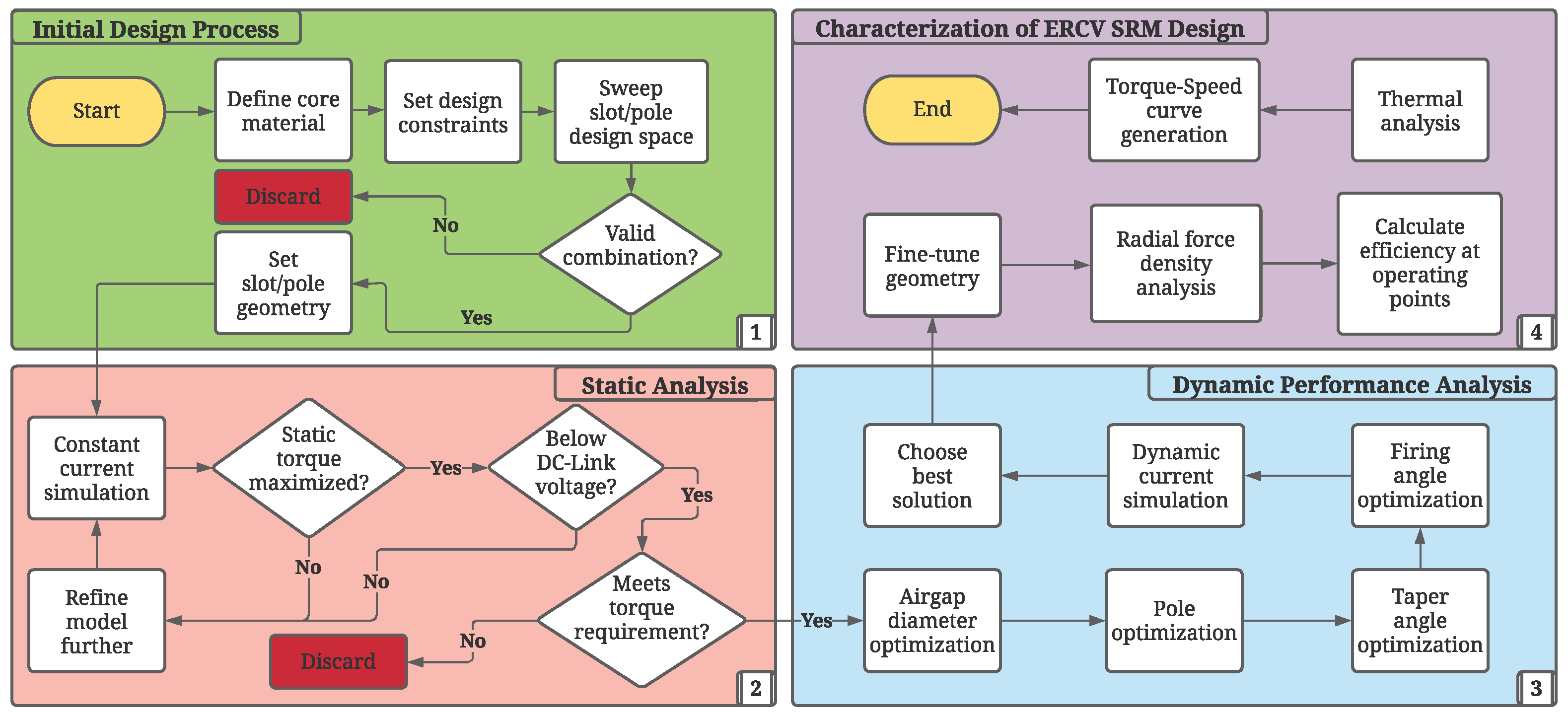
Section 3 details the proposed four-stage design process. In the first stage (Section 4), core material selection, design constraints, and possible slot/pole configurations are studied. The second and third design stages are presented in Section 5. The second stage consists of an iterative analysis of the static characteristics of all possible configurations to determine which one meets the desired requirements, while in the third stage, different optimizations are carried out to further improve the performance of the SRM. Dynamic profiles and performance results of the machine in two operating points are also shown in this section. Finally, in the last stage (
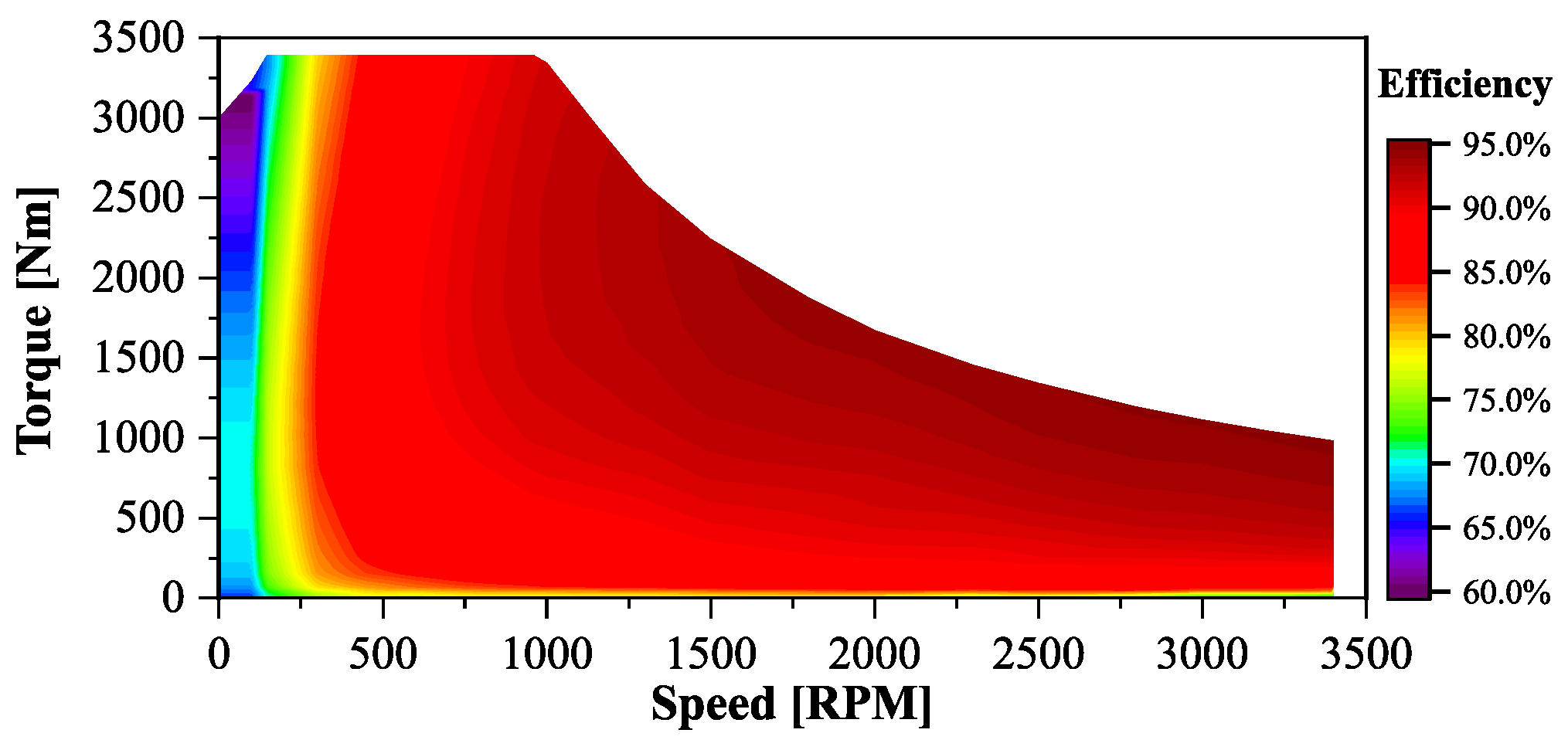
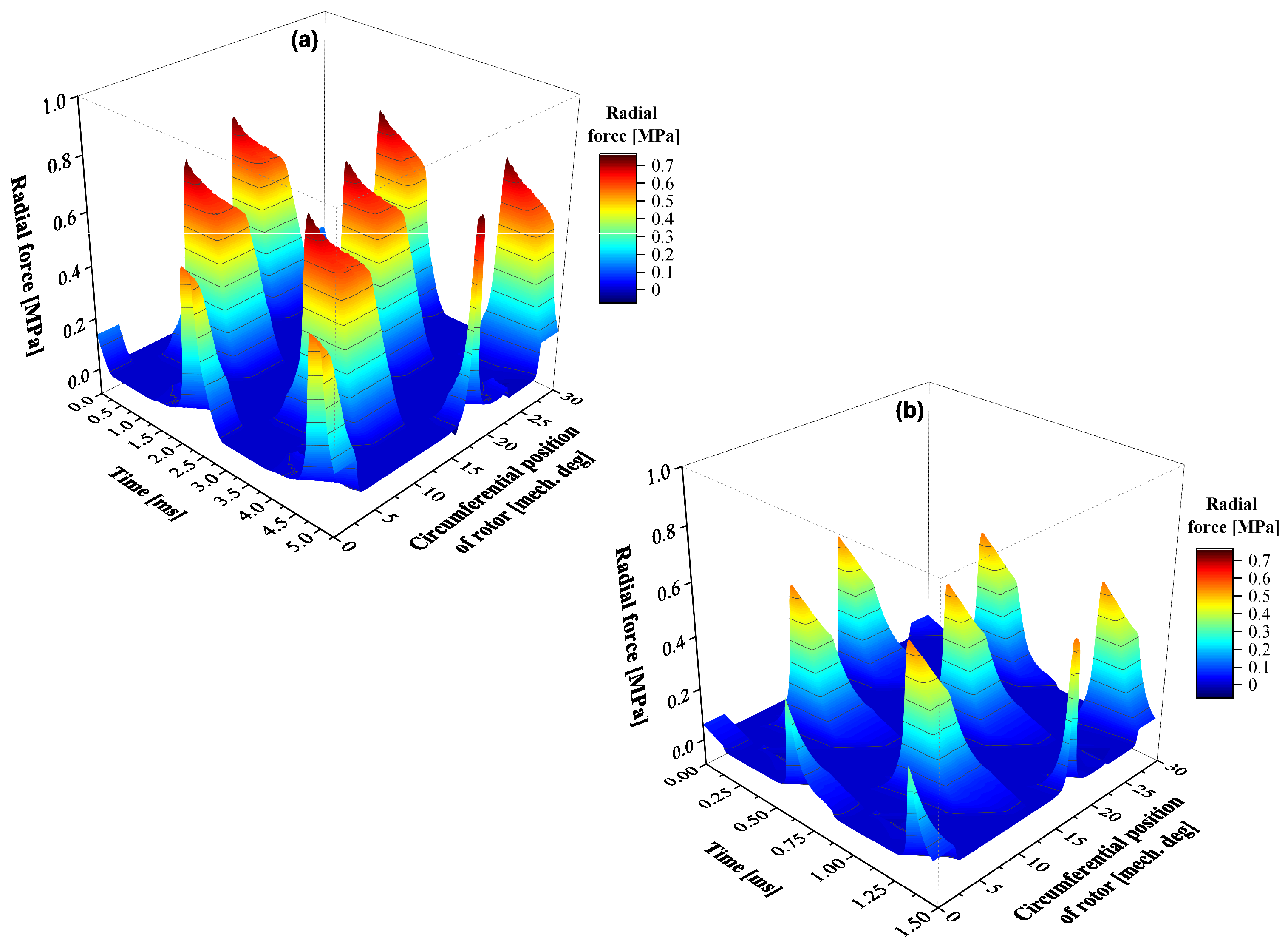
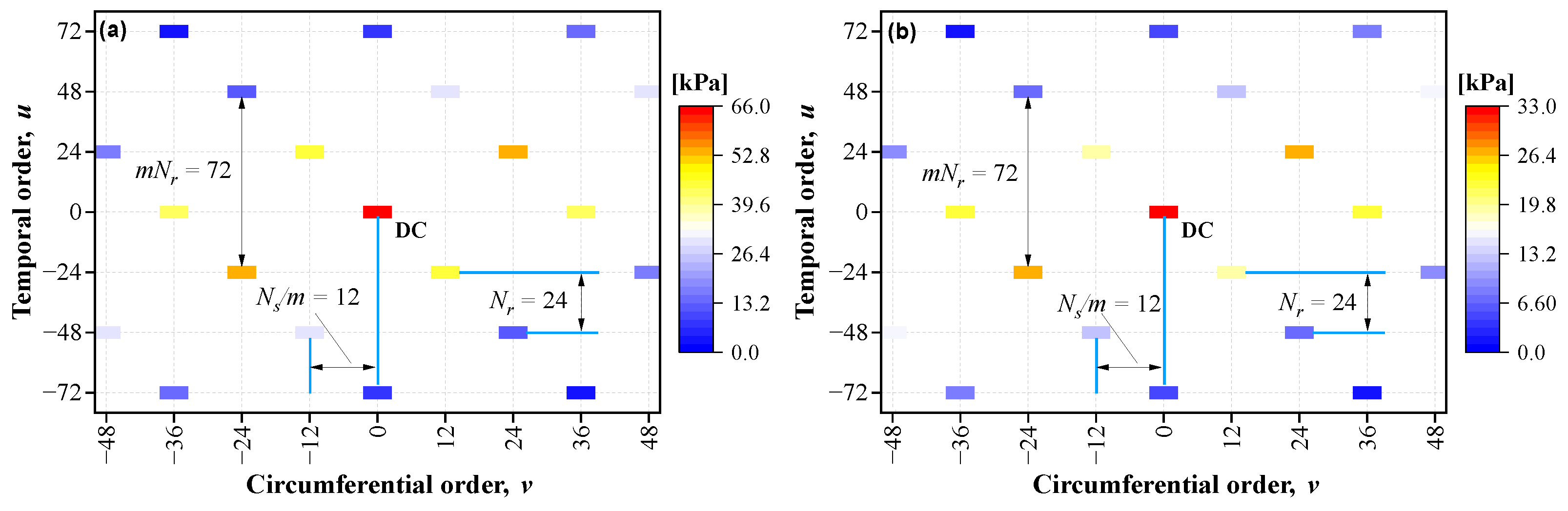
Section 6), the torque–speed efficiency map, radial forces, and thermal model are shown. The conclusions of this work are presented in Section 7.

2. Electric Refuse-Collecting Vehicles and the Benchmark Motor

Due to the limitations in terms of cost, weight, and energy density associated with battery technology in heavy-duty electric vehicles, motors with high efficiency and good specific power are desired to make the best use of limited energy. Permanent magnet motors are typically employed to this end. Today, there are a number of companies, such as Parker-Hannifin, ABB, and Dana TM4, manufacturing permanent magnet electric motors for ERCVs and trucks for different applications, such as mining, agriculture, construction, and the military.
In the case of Parker-Hannifin, its series of GVM310 motors are particularly well suited for class 8 ERCVs. These machines are in the range of 331 to 408 kW peak power, 1240 to 1430 Nm peak torque, with maximum speeds between 5010 and 6400 RPM, and would typically be employed in a dual motor configuration with a two-speed gearbox [16]. Similarly, ABB, an active company in the industrial and vehicle component manufacturing market, provides permanent magnet assisted synchronous reluctance machines for heavy-duty electric vehicles [17]. Some examples of these machines belong to the AMXE series (AMXE132/160/200/250) with peak mechanical power ranging from 250 to 680 kW and peak torque production capability from 600 to 3300 Nm [17].
Finally, Dana TM4, a joint venture between Dana Incorporated and Hydro-Québec, has the TM4 SUMO HD series for heavy-duty commercial vehicle applications [18]. The characteristics of these motors are 250 to 350 kW peak power, 2700 to 3400 Nm peak torque, and maximum speeds ranging from 2450 to 3400 RPM. These motors have nine phases with an outer rotor topology to improve the torque density and direct drive configuration without a gearbox [19]. In particular, the TM4 SUMO HD HV3500-9P [19] is selected as the benchmark for development of a heavy-duty truck traction SRM. Lion Electric has been using this motor in their ERCV line [2,20]. The electrical and mechanical specifications of the HV3500-9P are listed in 
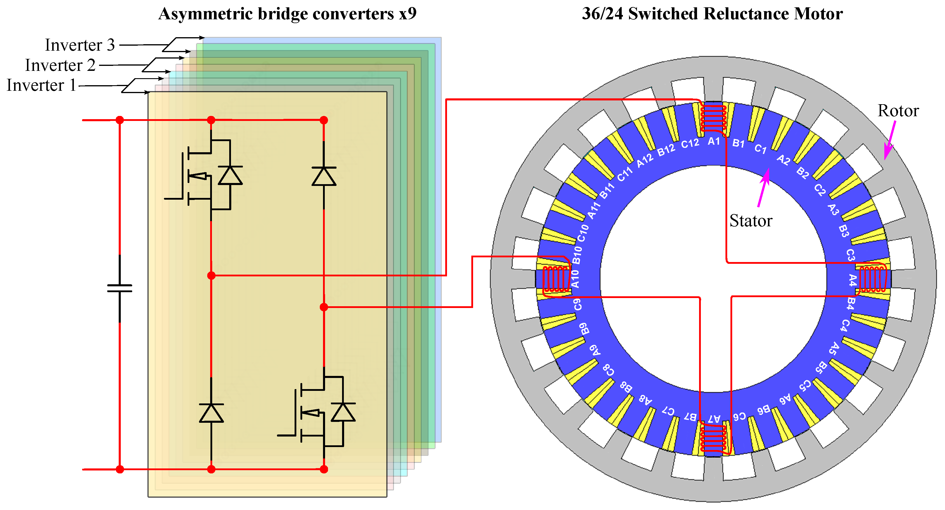
Table 2. It has been designed to interface directly with standard rear differentials or e-axles. It has a total of nine phases, split evenly into three independent inverter modules. This has the benefit of each module only requiring 1 / 3 of the total current, which reduces capacitor and wire gauge size at the expense of requiring more winding turns per coil [21]. 
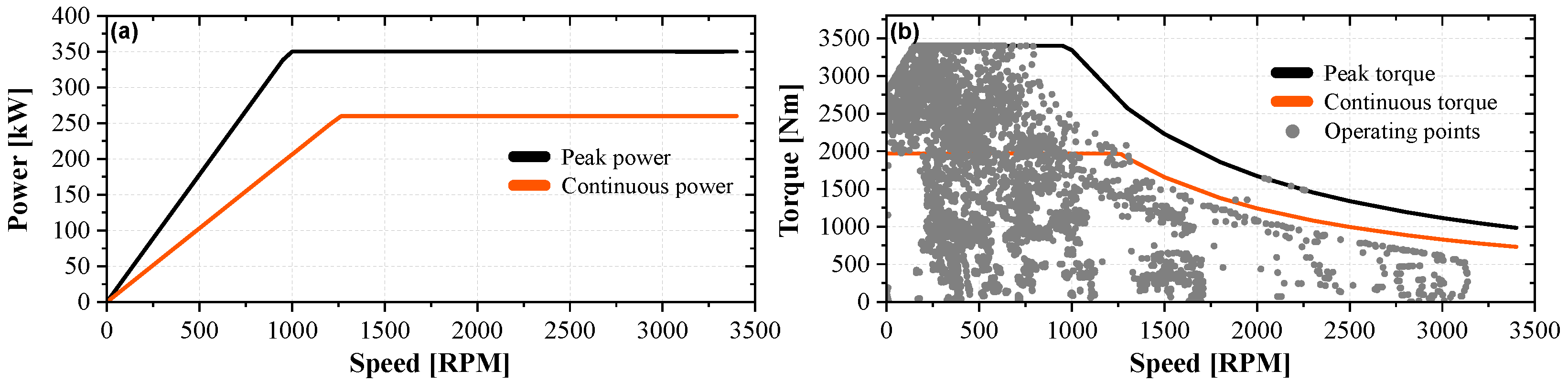
Figure 1a,b show the motor’s power–speed and torque–speed curves, respectively.
Notably, from 1000 RPM onward, the peak power is 350 kW, while from 1260 RPM onward, the continuous power is 260 kW. Regarding the dimensional specifications of the HV3500-9P shown in Table 2, the datasheet lists a length of 505 mm and a diameter of 572 mm. These dimensions include both the end caps and the cylindrical housing which add volume to the overall machine. Therefore, the values of active parts of the machine are estimated based on allowances for materials and gaps. The thermal specifications are also estimated based on typical maximum magnet temperature. In Figure 1b, operating points obtained in [1] from an ERCV simulation for the HV3500-9P are also depicted; please refer to [1] for further information.
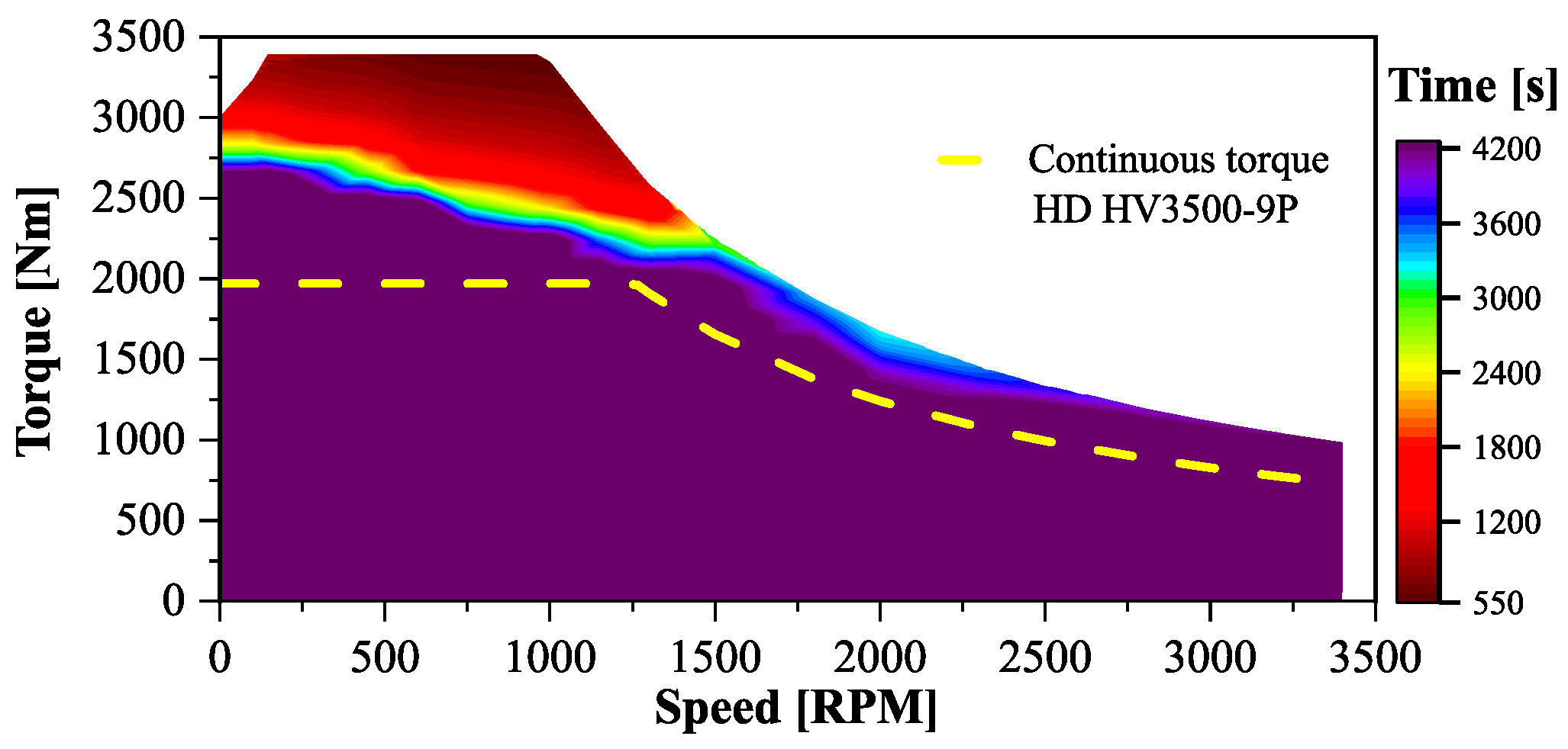
Statistical analysis of the vehicle’s torque–speed demand suggests that 87% of the operating points fall below the base speed of 950 RPM. This can be considered a particularly important region of operation for the motor. The analysis also reveals that 20% of the operating points are above the continuous torque, 2% are at the maximum torque, and ≪0.1% are above the continuous power rating of the machine.

3. Proposed Design Process for the ERCV Switched Reluctance Motor

The design of the ERCV switched reluctance motor is conducted in four stages, as depicted in Figure 2. It is worth mentioning that the design process does not strictly follow a linear path; certain steps can be repeated multiple times in an iterative loop until the desired results are obtained [23,24].
The general design constraints for the SRM were extracted from the HV3500-9P specifications and are listed in Table 3 and Table 4. A duration limit of 4200 s is selected for the continuous operating conditions. This is the time it takes to exhaust the 336 kWh battery referenced in Table 1 down to a 10% state of charge cut-off at the specified power rating. Notably, three independent asymmetric bridge converters will be used to power the machine, such that the phases from different converters (e.g., U1, U2, U3) are electrically synchronized. This enables the motor to operate similarly to a three-phase motor with parallel windings, without a phase shift between the winding sets. This approach is assumed to be similar to the winding configuration applied in the HV3500-9P motor.

4. Initial Design Process; Motor Sizing

The initial design process started with the selection of suitable materials. Electrical steel 35JN210 from JFE Steel was selected as the lamination material of choice due to its good permeability, high saturation flux density, and suitability for electric vehicle traction motors, as well as manufacturing capability for medium to large rotating machine sizes [25]. It also has low core loss that is suitable for the design requirements of an ERCV SRM. Further design constraints were then implemented in a MATLAB script which sorted through a 100 × 100 slot/pole matrix to identify suitable slot/pole options. These constraints included:
  • balanced three-phase winding,
  • stator pole multiples of nine for the capability to operate the motor with three inverters, where each inverter is a three-phase asymmetric bridge converter,
  • even number of stator poles per phase,
  • self-starting and unaligned condition capability,
    4 π m N r β s + β r 2 π N r
  • relative difference between stator and rotor poles less than 2 ° to avoid significant dead zone in torque profile,
    | β s β r | 2 °
  • slot and pole pitches greater than 10 mm,
where N r is the number of rotor poles, β s and β r are the stator and rotor pole arc angles, and 
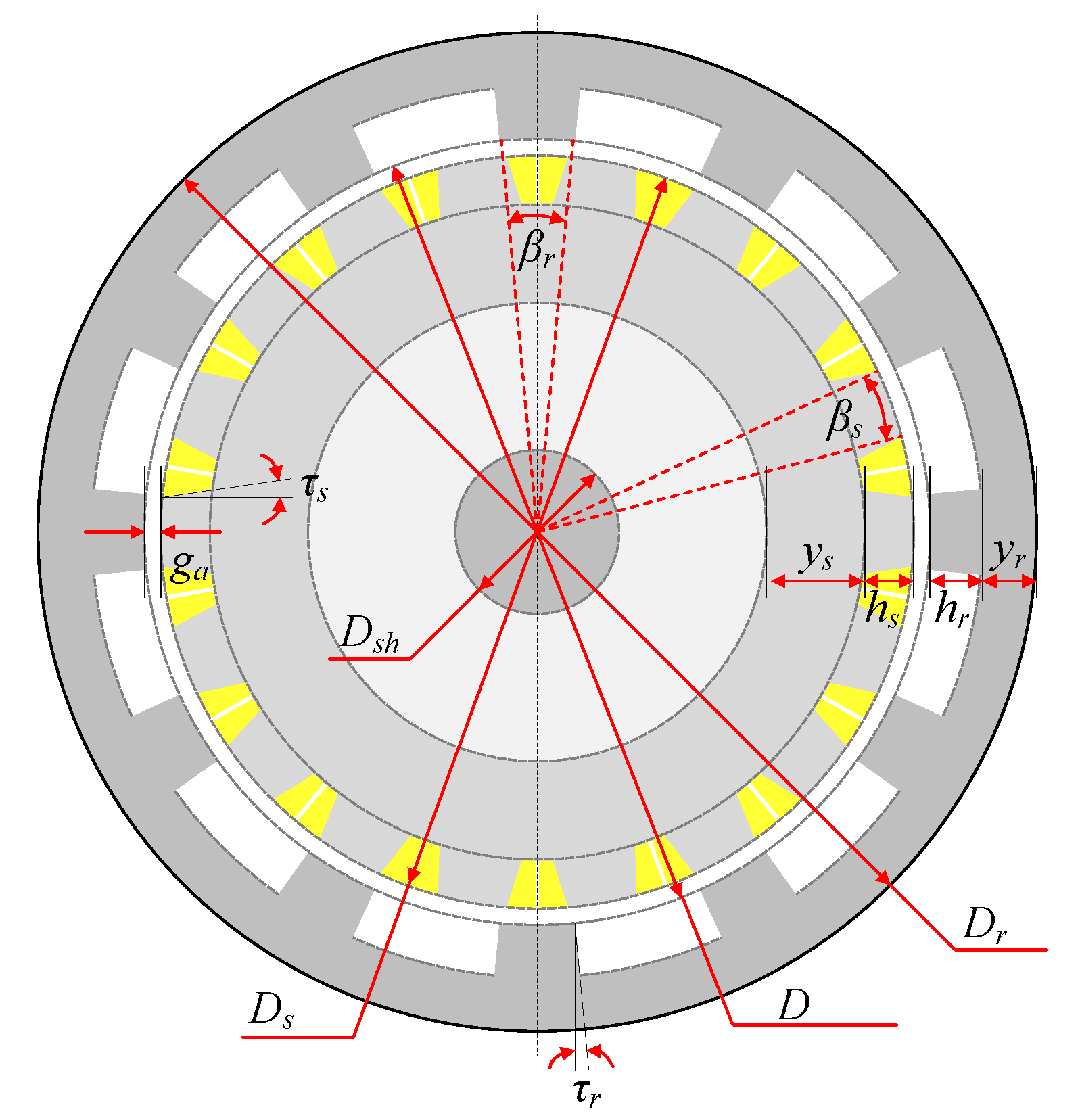
m is the number of phases. The mechanical dimensions of an example outer rotor SRM are shown in Figure 3. Six possible configurations that met the constraints were identified: 18/12, 18/24, 18/30, 18/42, 36/24, and 54/36. Initial mechanical dimensions for these configurations can be proposed based on the SRM design constraints shown in Table 3 while meeting the aforementioned constraints.

5. Static and Dynamic Performance Analyses

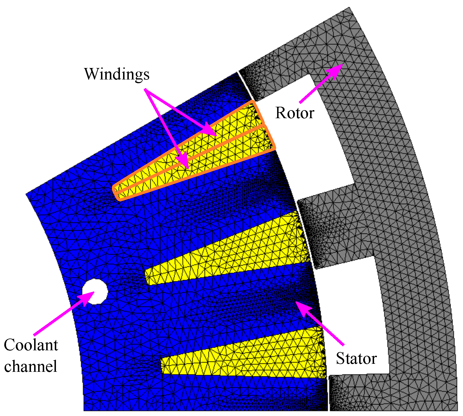
For the static and dynamic analyses, fractional motor models were developed and analyzed in JMAG, as shown in Figure 4. First, the static characteristics of suitable configurations were obtained and compared with the goal of maximizing torque while minimizing copper loss and induced voltage. To obtain such characteristics, sweeps of constant current in steps of 25 A were used, and mesh size was adjusted for the corresponding pole configuration as presented in [26].
Table 5 shows a normalized comparison of the static characteristics of the analyzed SRM configurations. Configurations 18/12, 18/24, and 54/36 show similar performance in terms of torque, while the 36/24 configuration has the highest static torque. As also shown in Table 5, the 36/24 configuration achieves the required torque in the static analysis, but it has slightly higher copper loss due to its phase resistance and also has high induced voltage. Further refinement was conducted on this configuration. Variations to the 36/24 geometry listed in Table 6 were systematically studied over numerous iterations.
Many trends that improved torque performance at the base speed also generally increased back EMF to the point where, at the maximum speed, the torque requirements could not be met due to insufficient current. For the selection of the final geometry, a balanced performance both at the base speed and maximum speed was essential to ensure that the full torque–speed curve of the benchmark motor could be achieved.
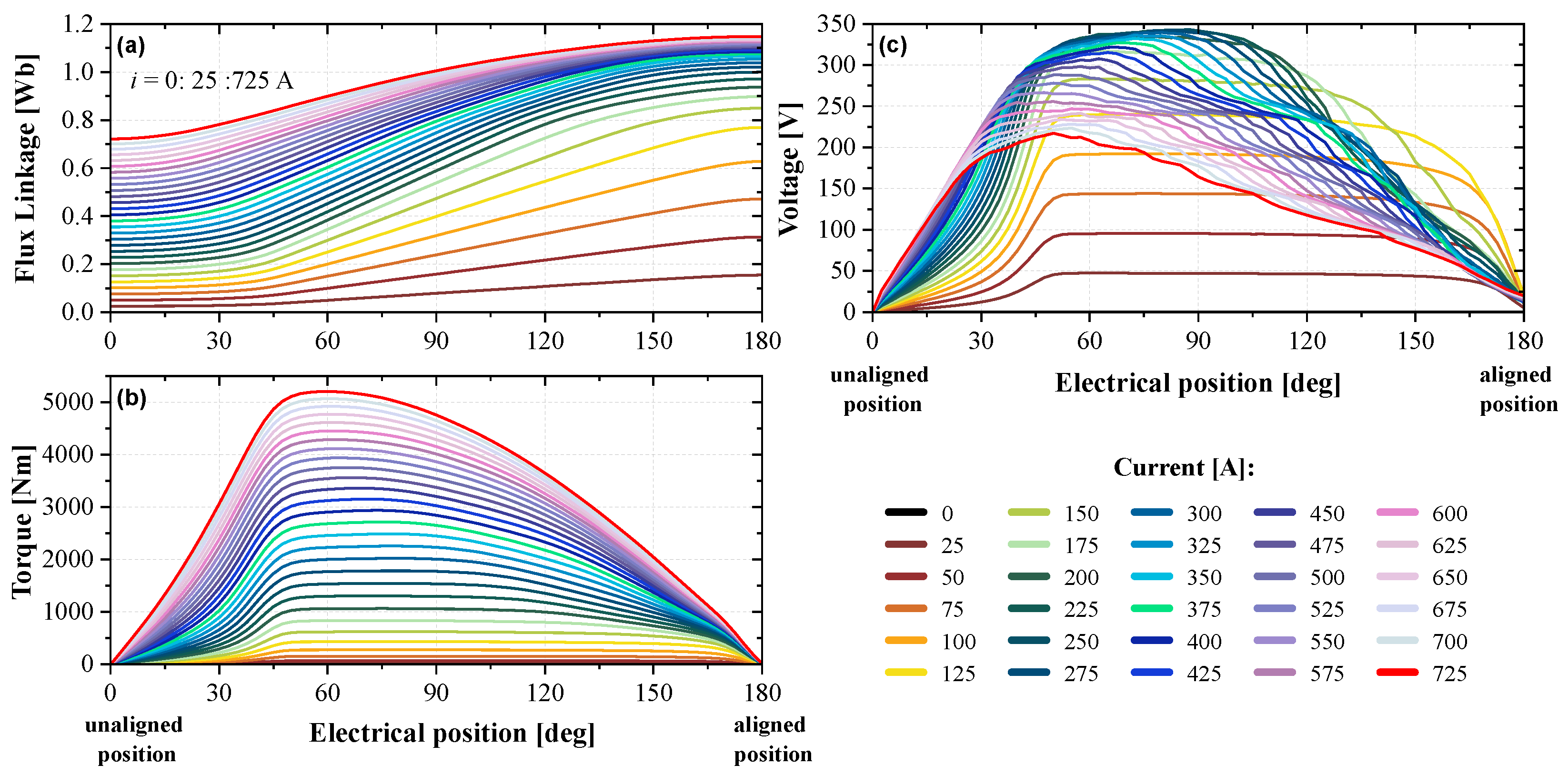
Figure 5 shows the static flux linkage, torque, and induced voltage profiles for the final design of the 36/24 SRM configuration. The effects of saturation on the flux linkage and voltage can be observed at higher currents.
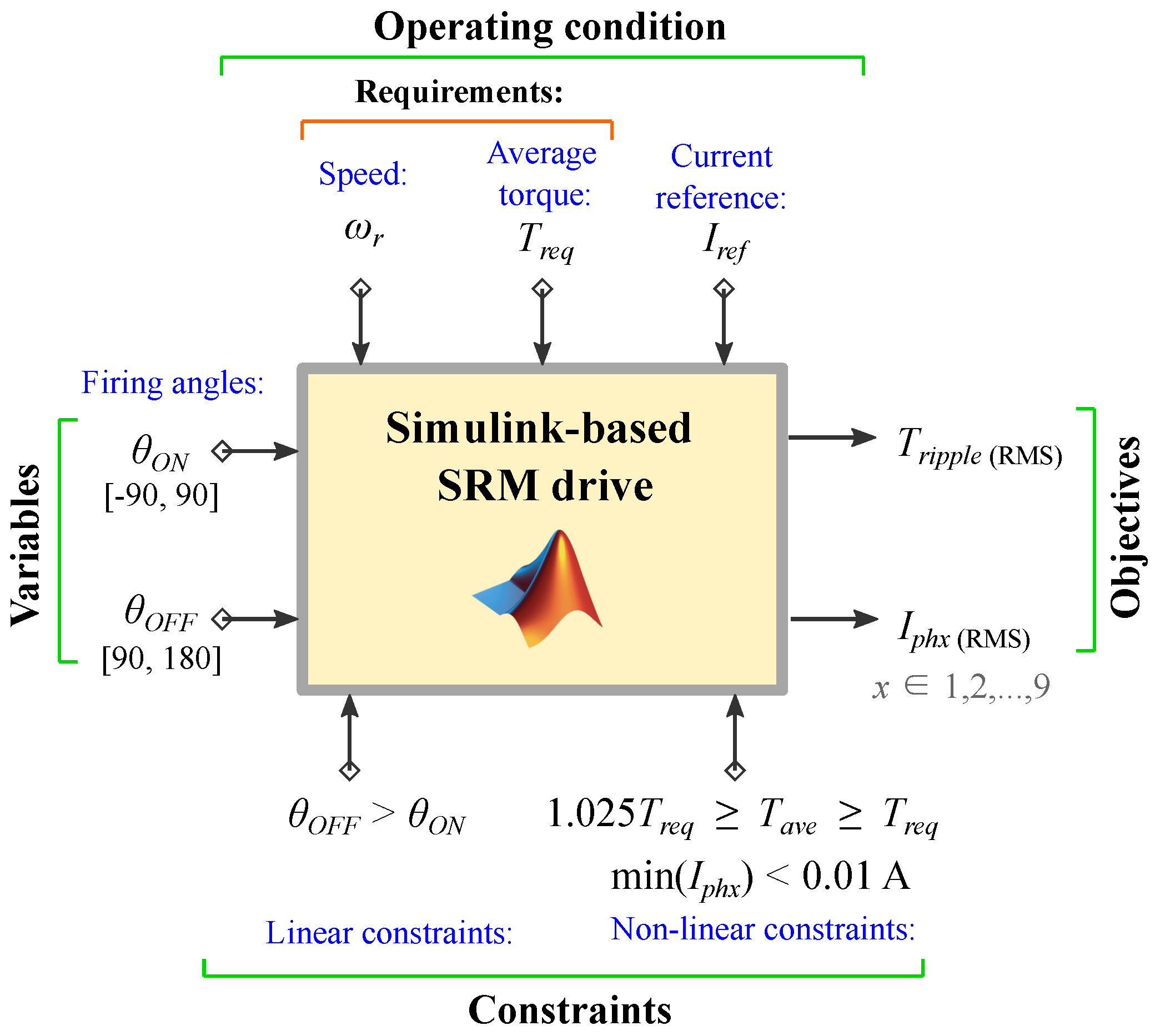
For the dynamic analysis, reference current and firing angle optimizations were carried out at different operating points. A genetic-algorithm (GA) multiobjective optimization was developed in MATLAB/Simulink as shown in Figure 6. This iterative optimization requires the designer to specify the mechanical speed ( ω r ) and the required average torque ( T r e q ) under different values of current reference ( I r e f ).
Turn-on and turn-off angles are restricted to be in the ranges of [−90, 90] and [90, 180] electrical degrees, respectively. Optimization objectives are defined as the RMS torque ripple and RMS current (fitness functions). Furthermore, linear and nonlinear constraints can also be added to the multiobjective optimization algorithm:
  • minimum value of phase current < 0.01 A to avoid continuous conduction mode (CCM) at high-speed operation,
  • average torque ≥ torque requirement,
  • average torque ≤ 102.5% of desired torque.
Equations (3) and (4) are required to calculate the dynamic average torque and RMS torque ripple, respectively [11]. In these expressions, T ( θ ) is the instantaneous torque, and ( θ 2 θ 1 ) is equal to a complete electrical cycle of the SRM. 
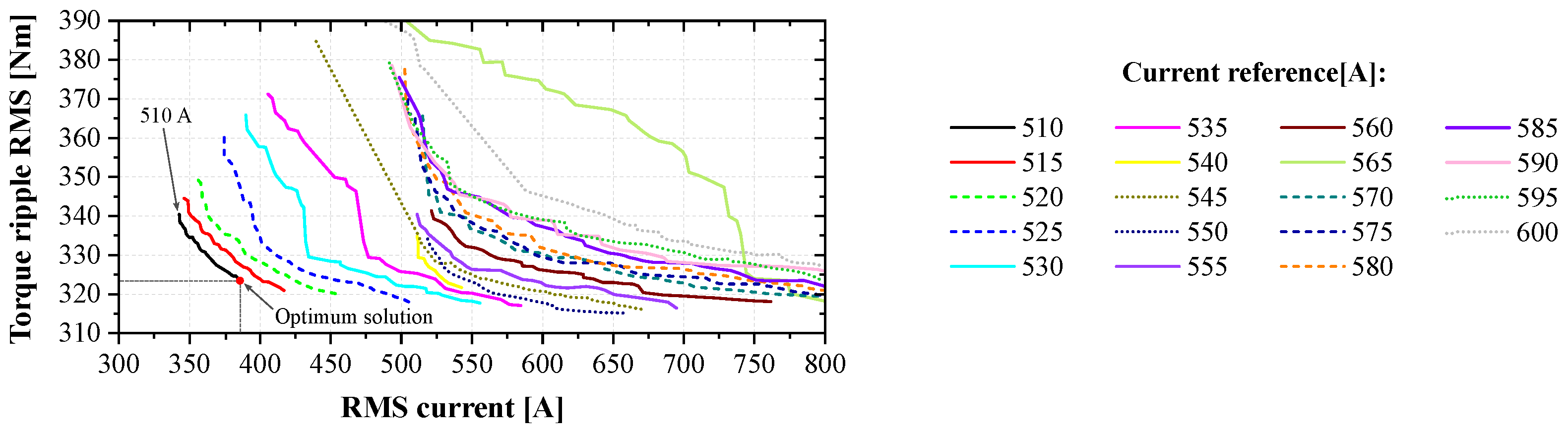
Figure 7 shows the results for the RMS torque ripple calculated in the GA multiobjective optimization as a function of RMS phase current at different current reference values at the base speed. Each point on each curve achieves the required torque T r e q and has a specific value for both, θ O N and θ O F F . Then, the selection of the optimum conduction angles is done by choosing the point with the lowest reference current, the lowest RMS current, and the lowest torque ripple RMS. Optimized values for I r e f , θ O N , and θ O F F for 950 RPM are 510 A, −22.85 ° , and 144.35 ° , respectively. In the case of the maximum speed, these values are 305 A, −66.42 ° , and 113.18 ° , respectively.
T a v e = 1 θ 2 θ 1 θ 1 θ 2 T ( θ ) d θ
T r i p p l e ( RMS ) = 1 θ 2 θ 1 θ 1 θ 2 T ( θ ) T a v e 2 d θ
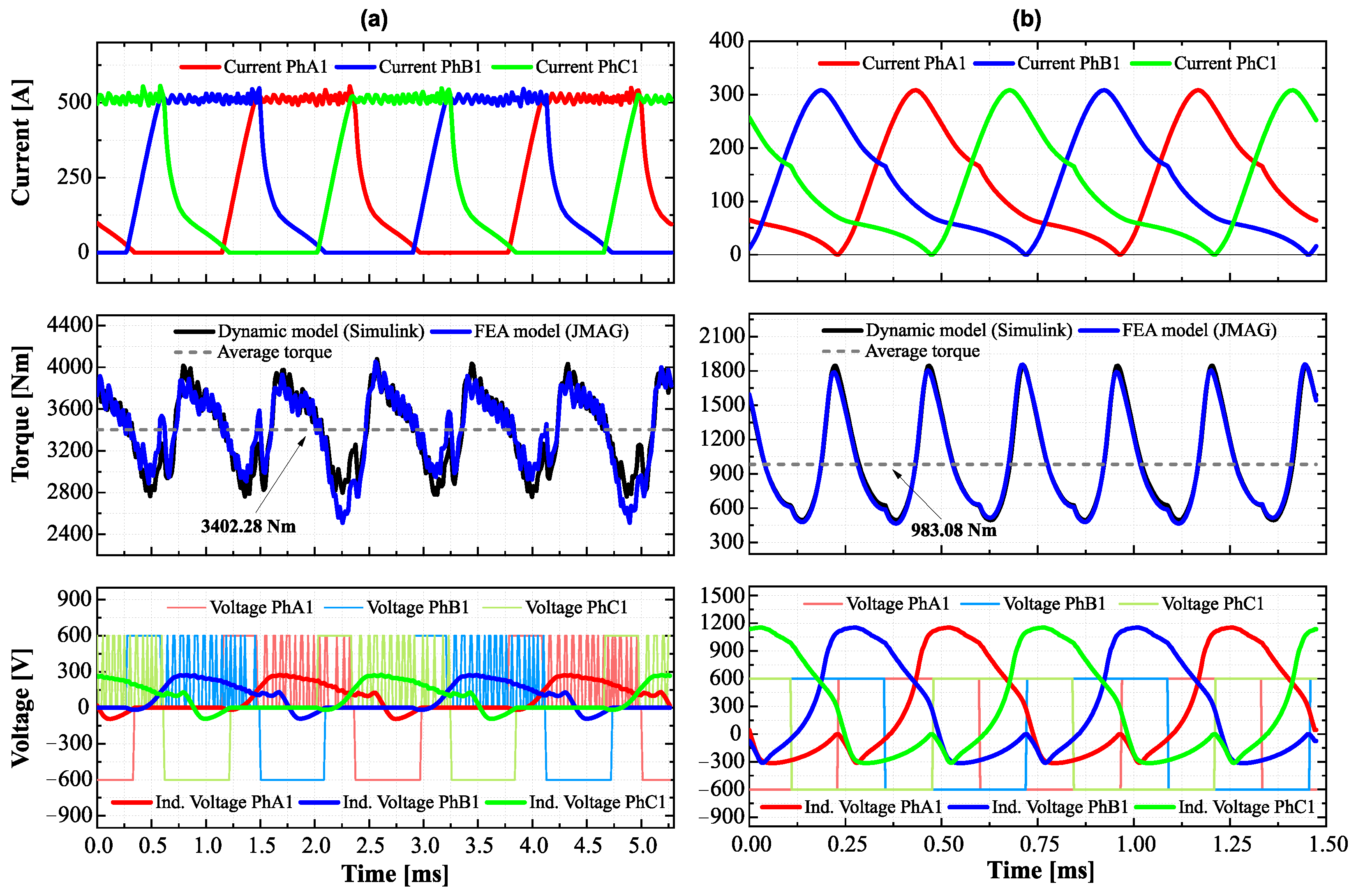
Figure 8a,b show the dynamic results for the 36/24 SRM at the base and maximum speeds, respectively. Please note that for the phase currents and phase voltages, one out of three three-phase sets is shown. The torque waveform is calculated for all three-phase sets combined. For both operating points, phase currents reach zero at the end of the conduction period. This enables lower current, especially at high-speed operation, to limit the copper losses. At 950 RPM, the hysteresis controller regulates the phase current at the reference value, I r e f = 510 A, as the induced voltage is lower than the DC-link voltage.
At the maximum speed, the controller operates in single pulse mode due to the high induced voltages. The torque results from the dynamic model of the motor in MATLAB/Simulink are compared with the waveforms calculated from JMAG finite element analysis (FEA) for the same phase currents. It can be observed that the torque waveforms match closely (less than 0.25% of difference). This suggests that the mutual coupling between phases is reasonably low, as the MATLAB model is faster to use, but does not take mutual coupling into account. Table 7 shows the performance results for these two operating points.

6. Characterization of the ERCV SRM Design

After the geometry is fine-tuned, the torque–speed curve and the efficiency map of the final motor design are developed. The radial forces are analyzed for the proposed design, and thermal analysis is conducted.

6.1. Final Geometry and Efficiency Map

The final geometry and winding parameters for the 36/24 SRM are presented in Table 8 and Table 9, respectively. Figure 9 illustrates the block diagram of the proposed SRM drive and the active elements of the machine. The windings of only one of the nine phases are represented and connected to their corresponding asymmetric bridge converter.
The efficiency map for the 36/24 SRM is shown in Figure 10. Efficiency at the base speed is around 91%, while the maximum efficiency of 94.8% is achieved at the maximum speed. The efficiency calculation incorporates the copper and iron losses. For the copper loss calculation, the phase resistance is calculated at 180 ° C.

6.2. Radial Force Analysis

The study of vibration and acoustic noise is important for any electric machine. In the case of the designed SRM, vibration and acoustic noise are mainly caused by radial force density harmonics in the outer rotor [27,28]. The radial forces can be considered as a time moving force density composed by temporal ( u ) and circumferential order ( v ) harmonics. The electromagnetic force density waveform in the airgap is shown in Figure 11a for 950 RPM and in Figure 11b for 3400 RPM. Similar to the dynamic results depicted in Figure 8, these simulations were run for two electrical cycles (30 ° in circumferential position).
The radial force density waveform for 950 RPM is higher in magnitude, as the average torque is also higher than that produced at 3400 RPM. Next, the 2D FFT of the radial force density waveform is obtained to observe the magnitude of the different harmonic orders. The location of these harmonics in the u-v plane depends on the SRM pole configuration. In the case of the 36/24 SRM, the circumferential spacing between harmonics is given by N s / m = 12 , while the temporal spacing is defined as the number of strokes m N r = 72 . The 36/24 SRM has twelve magnetic poles; therefore, the natural frequency of mode shape 12 is of particular importance. Figure 12a,b show the temporal and circumferential harmonic orders for the 36/24 SRM for 950 and 3400 RPM, respectively.

6.3. Thermal Analysis

A heat transfer model of the 36/24 ERCV SRM was created in Motor-CAD. The model uses an equivalent thermal circuit in order to analyze the thermal performance of the machine. For thermal management of the ERCV SRM, the stator is actively cooled via axial channels in the back-iron where dielectric coolant comes in direct contact with the laminations. For the thermal analysis, copper and iron losses were imported from JMAG. Table 10 shows the thermal model specifications. Based on the channel diameter and flow rate, the flow is turbulent; this promotes thermal mixing. A circular cross-section was selected to allow for connection to standard fittings between coolant channels, because coolant is not circulated through the axle or end plates.
The selected cooling configuration is fundamentally based on TM4 patent US6819016B2 for the liquid cooling of outer rotor machines [29]. In this patent, TM4 proposes the use of copper tubes embedded in the stator back-iron to irrigate coolant flow. For the thermal analysis of the ERCV SRM, copper tubes have not been included. The use of copper tubes needs to be further investigated taking into consideration assembly, core material selection, and thermal management. The 36/24 ERCV SRM design is totally enclosed, and the outer housing is cooled via natural convection. Forced air flow over the housing can improve thermal performance considerably, which can further improve thermal management of the motor. However, forced air flow of the outer housing is not considered to achieve a conservative design. Figure 13 shows temperatures on the radial cross-section of the motor at 1260 RPM and continuous torque of 1970 Nm. The axial cross-section at 3400 RPM and continuous power 260 kW can be seen in Figure 14.
Winding and steel temperatures are below 200 ° C for both operating points, making type K magnet wire insulation class suitable for this application. Figure 15 shows the transient temperature characteristics for base speed operation at the maximum torque. For the ERCV SRM, this is the most severe loading condition. It can be seen that the winding temperature exceeds 200 ° C after 550 s. As the peak operating requirement is 30 s, it can be concluded that the peak operating requirements are met. The maximum observed coolant pressure drop is 110 kPa over all cases; this is within the requirements given in Table 2. This pressure value is calculated automatically in Motor-CAD based on the fluid properties, coolant channel geometry and properties, coolant temperature, and flow rate.
Figure 16 shows the transient overheating time for the full torque–speed curve for the 36/24 SRM. The designed ERCV SRM allows for a similar continuous torque operation to the HD HV3500-9P, with a transient overheating time greater than 4200 s.

7. Conclusions

In this paper, the design of a high-power 36/24 SRM for ERCV traction applications was presented. The machine is designed to operate using nine phases split evenly into three independent three-phase segments that are synchronized with each other. The electrical and mechanical specifications of a commercial motor for a similar application, TM4 HD HV3500-9P, were used as a baseline. A proposed four-stage design process was followed. Through this process, the maximum torque requirement of 3400 Nm below the base speed, the maximum power requirement of 350 kW above the base speed, and the maximum speed requirement of 3400 RPM were achieved through simulations performed in MATLAB and JMAG. The calculated peak efficiency is 94.8%, and continuous (4200 s) and peak (550 s) operation temperatures were also verified to be below 200 ° C using Motor-CAD thermal simulations. Overall, this study suggests that the implementation of an SRM in an ERCV is viable from a thermal and electromagnetic standpoint. Coupled with the inherent benefits of SRMs over permanent magnet motors in terms of cost and durability, this may make an SRM the ideal choice for ERCV applications.

Author Contributions

Conceptualization, A.F. and F.J.-L.; methodology, A.F., F.J.-L. and B.B.; software, A.F. and F.J.-L.; validation, A.F., F.J.-L. and B.B.; formal analysis, A.F. and F.J.-L.; investigation, A.F. and F.J.-L.; resources, B.B.; data curation, A.F. and F.J.-L.; writing—original draft preparation, A.F. and F.J.-L.; writing—review and editing, A.F. and F.J.-L.; visualization, F.J.-L.; supervision, B.B.; project administration, B.B.; funding acquisition, B.B. All authors have read and agreed to the published version of the manuscript.

Funding

This research received no external funding.

Data Availability Statement

Not applicable.

Acknowledgments

The authors would like to thank Matworks for their support with MATLAB/Simulink, Powersys Solutions for their support with JMAG, and CMC Microsystems for their support with SolidWorks software in this research.

Conflicts of Interest

The authors declare no conflict of interest.

Abbreviations

The following abbreviations are used in this manuscript:
CCMContinuous Conduction Mode
ERCVElectric Refuse-Collecting Vehicle
FEAFinite Element Analysis
FFTFast Fourier Transform
PMSMPermanent Magnet Synchronous Motor
RCVRefuse-Collecting Vehicle
RMSRoot Mean Square
RPMRevolutions Per Minute
SRMSwitched Reluctance Motor

References

  1. Forsyth, A.; Juarez-Leon, F.; Bauman, J. Simulating Electric Refuse Collecting Vehicle Performance: Permanent Magnet Versus Switched Reluctance Traction Motor. In Proceedings of the IEEE Transportation Electrification Conference & Expo (ITEC), Anaheim, CA, USA, 15–17 June 2022; pp. 1225–1230. [Google Scholar]
  2. Lion Electric. All-Electric Lion 8 Refuse Truck. Available online: https://pages.thelionelectric.com/all-electric-lion8-refuse-truck-lion-electric/ (accessed on 10 October 2022).
  3. Sandhu, G.; Frey, C.; Bartelt-Hunt, S.; Jones, E. In-use activity, fuel use, and emissions of heavy-duty diesel roll-off refuse trucks. J. Air Waste Manag. Assoc. 2015, 65, 306–323. [Google Scholar] [CrossRef] [PubMed]
  4. Knoke, T.; Böcker, J. Optimal Power Train Design of a Hybrid Refuse Collector Vehicle. In Proceedings of the IEEE Vehicle Power Propulsion Conference, Arlington, TX, USA, 9–12 September 2007; pp. 815–820. [Google Scholar]
  5. Serrao, L.; Rizzoni, G. Optimal Control of Power Split for a Hybrid Electric Refuse Vehicle. In Proceedings of the American Control Conference, Seattle, WA, USA, 11–13 June 2008; pp. 4498–4503. [Google Scholar]
  6. Soriano, F.; Moreno-Eguilaz, M.; Álvarez-Flórez, J. Drive cycle identification and energy demand estimation for refuse-collecting vehicles. IEEE Trans. Veh. Technol. 2015, 64, 4965–4973. [Google Scholar] [CrossRef]
  7. Cortez, E.; Moreno-Eguilaz, M.; Soriano, F.; Cardoso, E. Estimation of Fuel Consumption in a Hybrid Electric Refuse Collector Vehicle Using a Real Drive Cycle. In Proceedings of the 42nd Annual Conference of the IEEE Industrial Electronics Society, Florence, Italy, 23–26 October 2016; pp. 4407–4412. [Google Scholar]
  8. Cortez, E.; Moreno-Eguilaz, M.; Soriano, F. Advanced methodology for the optimal sizing of the energy storage system in a hybrid electric refuse collector vehicle using real routes. Energies 2018, 11, 3279. [Google Scholar] [CrossRef]
  9. Erdinç, O.; Yetilmezsoy, K.; Erenoğlu, A.; Erdinç, O. Route Optimization of an Electric Garbage Truck Fleet for Sustainable Environmental and Energy Management. J. Clean. Prod. 2019, 234, 1275–1286. [Google Scholar] [CrossRef]
  10. Propulsion Québec—Cluster for Electric and Smart Transportation. The Lion Electric Co., Launches All-Electric Class 8 Urban Truck. Available online: https://propulsionquebec.com/en/2019/03/12/the-lion-electric-co-launches-all-electric-class-8-urban-truck/ (accessed on 4 October 2022).
  11. Bilgin, B.; Jiang, J.; Emadi, A. Switched Reluctance Motor Drives—Fundamentals to Applications, 1st ed.; CRC Press: Boca Raton, FL, USA, 2018. [Google Scholar]
  12. Jing, L.; Pan, Y.; Wang, T.; Qu, R.; Cheng, P. Transient Analysis and Verification of a Magnetic Gear Integrated Permanent Magnet Brushless Machine With Halbach Arrays. IEEE J. Emerg. Sel. Top. Power Electron. 2022, 10, 1881–1890. [Google Scholar] [CrossRef]
  13. Skowron, M.; Orlowska, T.; Kowalski, C.T. Detection of Permanent Magnet Damage of PMSM Drive Based on Direct Analysis of the Stator Phase Currents Using Convolutional Neural Network. IEEE Trans. Ind. Electron. 2022, 69, 13665–13675. [Google Scholar] [CrossRef]
  14. Zhong, Q.; Wang, K.; Mao, K.; Dong, B.; Kuang, Q. Fault-Tolerant Control of Demagnetization for Ultra-High-Speed PMSM Based on Improved Equivalent-Input-Disturbance Approach. In Proceedings of the 25th International Conference on Electrical Machines and Systems (ICEMS), Chiang Mai, Thailand, 29 November–2 December 2022; pp. 1–5. [Google Scholar]
  15. Bilgin, B.; Howey, B.; Callegaro, A.; Liang, J.; Kordic, M.; Taylor, J.; Emadi, A. Making the case for switched reluctance motors for propulsion applications. IEEE Trans. Veh. Technol. 2020, 69, 7172–7186. [Google Scholar] [CrossRef]
  16. Parker-Hannfin. GVM310 Global Vehicle Motor Permanent Magnet (PMAC) Motor for Mobile Systems. Available online: https://www.parker.com/Literature/Electromechanical Europe/Literature/192_300115_GVM310_catalog.pdf (accessed on 11 October 2022).
  17. ABB. Motors for Heavy Electric Vehicles. Available online: https://new.abb.com/motors-generators/iec-low-voltage-motors/heavy-electric-vehicles (accessed on 26 January 2023).
  18. DANA TM4. About Us. Available online: https://www.danatm4.com/about-us/ (accessed on 11 October 2022).
  19. DANA TM4. TM4 SUMO HD Motor/Inverter System. Available online: https://www.danatm4.com/wp-content/uploads/2019/04/TM4-SUMO-HD_Dana-TM4.pdf (accessed on 12 October 2022).
  20. E-Mobility Engineering. Lion8 Refuse Truck. Available online: https://www.emobility-engineering.com/lion8-refuse-truck/ (accessed on 13 October 2022).
  21. Toussaint, E. 5 Benefits of Multi-Phase Motors and Inverters. Available online: https://www.danatm4.com/blog/5-benefits-multi-phase-motors-inverters/ (accessed on 5 October 2022).
  22. Dana TM4. Operations and Maintenance Guide TG-0059_17. Available online: https://www.dana.com.au/pdfs/tm4/TG-0059_17%20TM4%20SUMO%20HD%20Ops%20and%20Maint%20Guide.pdf (accessed on 2 October 2022).
  23. Jiang, J.; Bilgin, B.; Emadi, A. Three-Phase 24/16 Switched Reluctance Machine for a Hybrid Electric Powertrain. IEEE Trans. Transp. Electrif. 2017, 3, 76–85. [Google Scholar] [CrossRef]
  24. Howey, B.; Bilgin, B.; Emadi, A. Design of an External-Rotor Direct Drive E-bike Switched Reluctance Motor. IEEE Trans. Veh. Technol. 2020, 69, 2552–2562. [Google Scholar] [CrossRef]
  25. JFE. Electrical Steel Sheets, JFE G-Core, JFE N-Core, Datasheet. Available online: https://www.jfe-steel.co.jp/en/products/electrical/catalog/f1e-001.pdf (accessed on 5 September 2022).
  26. Liang, J.; Jiang, J.; Callegaro, A.; Bilgin, B.; Dong, J.; Reeves, D.; Emadi, A. Prediction of Acoustic Noise and Vibration of a 24/16 Traction Switched Reluctance Machine. IET Electr. Syst. Transp. 2020, 10, 35–43. [Google Scholar] [CrossRef]
  27. Liang, J.; Callegaro, A.; Howey, B.; Bilgin, B.; Dong, J.; Lin, J.; Emadi, A. Analytical Calculation of Temporal and Circumferential Orders of Radial Force Density Harmonics in External-Rotor and Internal-Rotor Switched Reluctance Machines. IEEE Open J. Ind. Appl. 2021, 2, 70–81. [Google Scholar] [CrossRef]
  28. Liang, J.; Howey, B.; Bilgin, B.; Emadi, A. Source of Acoustic Noise in a 12/16 External-Rotor Switched Reluctance Motor: Stator Tangential Vibration and Rotor Radial Vibration. IEEE Open J. Ind. Appl. 2020, 1, 63–73. [Google Scholar] [CrossRef]
  29. Houle, M.; Langlois, A. Liquid Cooling Arrangement for Electric Machines. US Patent 2004OO12272A1; filled 18 July 2002, and issued 22 January 2004,
Figure 1. TM4 SUMO HD HV3500-9P performance characteristics: (a) power–speed curve and (b) torque–speed curve.
Machines 11 00274 g001
Figure 2. SRM proposed design process.
Machines 11 00274 g002
Figure 3. Dimensions for an outer-rotor SRM, illustrated in an 18/12 configuration.
Machines 11 00274 g003
Figure 4. JMAG fractional model of 36/24 SRM.
Machines 11 00274 g004
Figure 5. Static characteristics of the 36/24 SRM at 1000 RPM (i = 0:25:725 A): (a) flux linkage, (b) torque, and (c) voltage.
Machines 11 00274 g005
Figure 6. GA multiobjective optimization.
Machines 11 00274 g006
Figure 7. GA multiobjective optimization results for ω r = 950 RPM, T r e f = 3400 Nm, I r e f = 510 , 515 , , 600 A.
Machines 11 00274 g007
Figure 8. Dynamic results for the 36/24 SRM at (a) 950 RPM and (b) 3400 RPM. From top to bottom: phase currents, torque, and phase and induced voltages.
Machines 11 00274 g008
Figure 9. 36/24 SRM drive.
Machines 11 00274 g009
Figure 10. Efficiency map for the 36/24 ERCV SRM.
Machines 11 00274 g010
Figure 11. Radial force density of the 36/24 SRM at (a) 950 RPM and (b) 3400 RPM.
Machines 11 00274 g011
Figure 12. Dominant radial force density harmonics of the 36/24 SRM at (a) 950 RPM and (b) 3400 RPM.
Machines 11 00274 g012
Figure 13. Steady-state temperatures in the radial cross-section of SRM at 1260 RPM and 1970 Nm.
Machines 11 00274 g013
Figure 14. Steady-state temperatures in the axial cross-section of SRM at 3400 RPM and 730 Nm.
Machines 11 00274 g014
Figure 15. Transient thermal characteristics at the peak torque operation, 3400 Nm at 950 RPM.
Machines 11 00274 g015
Figure 16. Transient overheating time for 36/24 ERCV SRM.
Machines 11 00274 g016
Table 1. Lion8 All-Electric refuse truck specifications.
ParameterValueUnit
Maximum power350kW
Maximum torque3400Nm
Maximum battery size336kWh
Top speed105km/h
Table 2. TM4 SUMO HD HV3500-9P—Electrical and mechanical specifications [19,22].
ParameterValueUnit
Rotor configurationOuter
Motor typePermanent magnet
Number of phases9
Peak power350kW
Continuous power260kW
Operating speed0–3400RPM
Peak torque3400Nm
Continuous torque1970Nm
DC-link voltage600V
Ambient temperature45 ° C
Max. coolant inlet temperature65 ° C
Coolant typeEGW 60/40
Max. coolant pressure207kPa
Peak power duration30s
Rotor outer diameter *510mm
Stator axial length *400mm
Max. temperature rise *75–105 ° C
Current density *10–20ARMS/mm 2
Motor mass340kg
* Estimated values.
Table 3. SRM design constraints.
ParameterValueUnit
Rotor configurationOuter rotor
Peak power350kW
Continuous power260kW
Operating speed0–3400RPM
Peak torque3400Nm
Continuous torque1970Nm
DC-link voltage600V
Ambient temperature45 ° C
Max. coolant inlet temperature65 ° C
Coolant type40/60 Water-Ethylene Glycol
Peak power duration30s
Continuous power duration4200s
Rotor outer diameter *510mm
Stator axial length *400mm
* Estimated values.
Table 4. SRM main operating targets.
Speed [RPM]Torque [Nm]Time [s]
950340030
126019704200
340098330
34007304200
Table 5. Slot/pole configuration; normalized comparison of static characteristics.
N s / N r TorqueInduced VoltageCopper Losses
18/120.7320.8270.521
18/240.7470.3430.469
18/300.3190.1860.347
18/420.3060.2200.315
36/241.0001.0000.858
54/360.7040.4981.000
Table 6. 36/24 SRM; geometry variation.
ParameterSymbolValueUnit
Stator pole arc angle β s 4.5:0.5:6.0deg
Rotor pole arc angle β r 4.0:0.5:8.0deg
Stator pole height h s 50:2:60mm
Rotor pole height h r varies with h s mm
Rotor back iron thickness y r varies with h s mm
Airgap length g a 0.5:0.25:1.0mm
Stator taper angle τ s 0.5:0.5:2.0deg
Rotor taper angle τ r 0.5:0.5:2.0deg
Table 7. 36/24 SRM performance results.
Parameter [Unit]Symbol@950 RPM@3400 RPM
Current reference [A] I r e f 510305
Turn-on angle [deg] θ O N −22.85−66.42
Turn-off angle [deg] θ O F F 144.36113.18
Induced peak voltage [V] V i n d 2781155
Average torque [Nm] T a v e 3398981
Torque ripple RMS [Nm] T r i p p l e 356437
Phase current RMS [A] I p h 328160
Copper losses [kW] P CU 25.36.0
Iron losses [kW] P FE 1.413.4
Output power [kW] P o u t 338.0349.1
Efficiency [%] η 91.294.8
Power Duration [s]5504200
Table 8. Final design parameters of 36/24 ERCV SRM.
ParameterSymbolValueUnit
Number of stator poles N s 36
Number of rotor poles N r 24
Number of phasesm9
Bore diameterD429.5mm
Stator outer diameter D s 428mm
Rotor outer diameter D r 510mm
Shaft diameter D s h 76mm
Stator pole height h s 52mm
Rotor pole height h r 19.25mm
Stator pole arc angle β s 5.5deg
Rotor pole arc angle β r 6deg
Stator taper angle τ s 1.5deg
Rotor taper angle τ r 1.5deg
Stator back iron thickness y s 25mm
Rotor back iron thickness y r 21mm
Airgap length g a 0.75mm
Fillet radius tip stator ζ s 0.5mm
Fillet radius bottom stator γ s 0.5mm
Fillet radius tip rotor ζ r 0.5mm
Fillet radius bottom rotor γ r 0.5mm
Stack length l s t a c k 375mm
Stacking factorSF95%
Table 9. Winding design parameters of 36/24 ERCV SRM.
ParameterSymbolValueUnit
Wire gauge19AWG
Wire insulationTriple
Number of turns per coil N t u r n 6turns
Number of strands per coil N s t r 35strands
Wire slot fill factor f f w i r e 59.8%
Phase resistance R p h a s e 26m Ω
Table 10. 36/24 SRM thermal model specifications.
ParameterValueUnit
Coolant inlet temperature65 ° C
Coolant flow rate12lpm
Coolant channels12
Channel configurationSeries
Coolant typeEGW 60/40
Disclaimer/Publisher’s Note: The statements, opinions and data contained in all publications are solely those of the individual author(s) and contributor(s) and not of MDPI and/or the editor(s). MDPI and/or the editor(s) disclaim responsibility for any injury to people or property resulting from any ideas, methods, instructions or products referred to in the content.

