Article

Hard Milling Process Based on Compressed Cold Air-Cooling Using Vortex Tube for Sustainable and Smart Manufacturing

1
Faculty of Technology, School of Mechanical and Design Engineering, University of Portsmouth, Portsmouth PO1 3DJ, UK
2
Faculty of Electrical Engineering, Mechanical Engineering and Naval Architecture, University of Split, FESB, R. Boskovica 32, 21000 Split, Croatia
*
Author to whom correspondence should be addressed.
Machines 2023, 11(2), 264; https://doi.org/10.3390/machines11020264
Submission received: 21 January 2023 / Revised: 4 February 2023 / Accepted: 7 February 2023 / Published: 10 February 2023
(This article belongs to the Special Issue Advances in Smart Manufacturing and Industry 4.0)

Abstract

:
Improving machining performance and meeting the requirements of sustainable production at the same time represents a major challenge for the metalworking industry and scientific community. One approach to satisfying the above challenge is to apply different types of cutting fluids or to optimise their usage during the machining process. The fact that cutting fluids are well known as significant environmental pollutants in the metalworking industry has encouraged researchers to discover new environmentally friendly ways of cooling and lubricating in the machining process. Therefore, the main goal is to investigate the influence of different machining conditions on the efficiency of hard machining and find a sustainable solution towards smart manufacturing. In the experimental part of the work, the influence of various machining parameters and conditions on the efficiency of the process was investigated and measured through the surface roughness, tool wear and cutting force components. Statistical data processing was carried out, and predictive mathematical models were developed. An important achievement is the knowledge of the efficiency of compressed cold air cooling for hard milling with the resulting lowest average flank wear of 0.05 mm, average surface roughness of 0.28 µm, which corresponds to grinding procedure roughness classes of N4 and N5, and average tool durability increase of 26% compared to dry cutting and conventional use of cutting fluids. Becoming a smart machining system was assured via technological improvement achieved through the reliable prediction of tool wear obtained by radial basis neural networks modelling, with a relative prediction error of 3.97%.

1. Introduction

Manufacturing is one of the essential human activities, and it has been and shall remain the foundation of a very strong economy. There is no other sector that could replace manufacturing within that role. Without a strong manufacturing base, other sectors such as the service and financial sectors could collapse [1]. As an engine of growth, the manufacturing sector has vastly expanded economic development [2]. Productivity growth of the manufacturing sector is positively related to the growth of the manufacturing sector’s output with increases in the returns in terms of lower average costs and positive effects on capital accumulation and technical progress as drivers of this mechanism [3]. Within the manufacturing sector, the metalworking industry has been one of the most rapidly developing and growing industries in recent years. The vast majority of metal parts that are used as a component of different products were shaped using some of the material removal processes. Conventional machining processes are the most frequently applied material removal processes of metals and are one of the most important manufacturing processes. The Industrial Revolution and the growth of manufacturing-based economies of the world can be traced largely to the development of various machining operations [4]. Considering different types of manufacturing such as one-off and batch production, machining processes cannot be replaced with any other type of process, and as such, in many cases, it represents the only technologically feasible and economically profitable method of production. When planning the machining process and choosing values of the input parameters (cutting parameters), the decision closely depends on geometric dimensioning and tolerancing, together with machined surface quality. High-performance cutting parameters assure higher productivity; however, they can result in surface quality deterioration and excessive tool wear [5]. Consequently, cutting fluids (CFs) were introduced into the manufacturing industry to reduce the temperature within the cutting zone and minimise the friction wear between the workpiece and the tool, and all through their cooling and lubrication effect. The global CF demand was expected to reach 2.2 million tonnes in 2022, with Asia as the largest consumer [6]. For instance, producers within the European Union are consuming approximately 320,000 tonnes of CFs yearly in various machining processes [7]. Using CFs increases productivity, improves the surface, reduces the costs of further processing and, consequently, increases total profits. However, modern life requires the introduction of new parameters in the equation of pursued success, such as sustainability with its three main pillars, namely, environmental and social acceptability and better economic feasibility. Recent demands resulting from these three dimensions together with CFs’ functional aspects should be the drivers for the future development of any new types of CFs or new types of application techniques (Figure 1).
Approximately 85% of the cutting fluids used around the world are mineral-oil-based CFs, having the highest demand among other types [8]. In 2011, 1.76 billion litres of mineral oil base fluids were used worldwide to produce cutting fluids [9]. Mineral-oil-based CFs consist of different toxic components that are hazardous in storage and disposal and as such presents a significant threat both to environmental pollution and human health. By observing the loss of cutting fluids such as evaporating, uncontrolled leakage, residuals on the workpiece, cutting tool or shavings, it can be concluded that almost 30% of the annual quantity of cutting fluid is lost in the manufacturing system by means of the abovementioned processes [10]. The disposal of used cutting fluids poses numerous environmental questions, particularly when it is known that they represent one of the most complex types of waste [11]. The National Institute for Occupational Safety and Health (NIOSH) estimates that at the state level, 1.2 million workers are exposed to the adverse effects of cutting fluids annually [12]. NIOSH adopted a document on the criteria for a recommended standard in relation to working conditions in the machining industry. The same document underlines the negative influence of cutting fluids due to the effect of the formation of oil mist. Among the most frequent diseases are different skin diseases and cancerous and noncancerous tumours of the respiratory system [13,14]. Other hazards such as the effect of oil vapours, bacterial effects, genotoxic effects, the generation of cancerogenic substances and the presence of heavy metals in additives are constant subjects of discussion with numerous possible short- and long-term consequences for humans [15,16]. Another disadvantage of using of CFs is their cost. When machining medium-hard materials, the cost of cutting fluid usage can reach up to 17% of the total machining costs [17], while the same cost when dealing with difficult-to-cut materials ranges between 20% and 30% of the total machining costs [18].
Many recent researchers have shown the tendency, but also the possibilities, of switching to dry machining, in which case the sociological and environmental conditions of sustainability would be automatically met [19,20,21]. The advantages of dry machining are multiple, and many authors point out the following: The non-existence of any harmful effect on humans and the environment, the reduction of variable machining costs due to the non-usage of cutting fluids, easier recycling of a chip with no residuals of CFs on it, reduced cleaning after machining of the workpiece and, in some cases, the possibility of applications of high-speed machining resulting in a reduction of cutting forces and consequently longer tool life [22,23,24]. However, the question of fulfilling the economic condition of sustainability of dry machining still remains open, and further answers are expected from scientists in the field of production engineering.
Following Figure 1, meeting all sustainability demands at the same time in order to develop better/smarter solutions represents a huge challenge. During the last two decades, many attempts to achieve sustainability in machining were successful and led to the development of alternative types of cooling and lubrication in machining. Among the most frequently used alternative techniques, one must single out techniques such as minimum quantity lubrication (MQL), Micro-jet MQL, cryogenic cooling (CC), compressed cold air cooling (CCAC) and vegetable-based cutting nanofluids.
MQL, also known as near-dry machining, is a lubrication method where very small quantities of lubricant are applied to the machining zone [23]. A low tribological-interface temperature is provided by the tribological film formed by homogenous mists in MQL-based fluids [19]. In relation to dry machining, the MQL technique provides the possibility of machining materials that necessarily require lubrication while at the same time decreasing the machining process’ environmental contamination, health risks and high energy consumption [24]. MQL greatly minimises the utilisation of cutting fluid and, hence, significantly minimises the lubrication cost when compared to conventional methods such as flooding [25]. Researchers indicate certain deficiencies of the MQL technique such as the high investment cost, MQL system maintenance costs, lack of function of chip removal, low amount of lubricant reaching the cutting zone and mist filtering and disposal problems [25]. Some of the drawbacks, such as difficulties with the lubricant reaching the cutting zone, have been overcome by using new application techniques such as Micro-jet MQL [19]. The advantage of the Micro-jet MQL system is that, due to the high pressure through the small nozzle diameter, the lubricant can successfully reach the cutting zone and fulfil its function. Despite the advantages and shortcomings of this technique, before making a decision on its implementation, it is necessary to perform a cost–benefit analysis.
Cryogenic processes present another cooling-based sustainable type of machining, mostly using liquid nitrogen at temperatures of up to −196 °C [16]. Going back to its beginning in the 1900s, cryogenic machining first used carbon dioxide, and, later on, even liquid helium was introduced as a coolant. When a cryogenic coolant is used in the machining process, the evaporation of liquid nitrogen does not represent any hazard to the environment or workers’ health. The same does not apply to carbon dioxide, which pollutes the atmosphere. However, extremely low temperatures of cryogenic fluids pose an injury hazard due to contact with cryogenic fluids when maintaining the system itself or during manual adjustment of the above-mentioned technique to a particular tool, the geometry of the workpiece or type of machining [26]. Cryogenic cooling was proven to be successful when machining difficult-to-cut materials such as titanium-based alloys and nickel-chromium-based alloys [27,28]. In order to ensure the correct conditions for high-performance machining for the prolonging of tool life, it is necessary to spray large quantities of cryogenic fluids during machining in an efficient way. The abundant use of cryogenic fluids and the cost of investment for the system for the supply and spraying of fluids in the cutting area eventually increases the total machining costs of the process and introduces the need to conduct research on the economical sustainability of cryogenic processes [29].
CCAC air is a relatively new machining cooling technique. In initial research, only room-temperature compressed air was used, which, in relation to certain functions of the conventional usage of CFs, proved inferior. Experimental research conducted in recent years classified cooling using compressed cold air as an extremely efficient alternative cooling technique. Evaporation of a medium such as air in the atmosphere without the possibility of contamination, the extension of the tool’s life, the lack of chips from residual oil and the non-existence of harmful impacts on human health when exposed to these agents are just some of the positive characteristics of this cooling technique [30]. Cooling using compressed cold air during machining can be performed by using specifically designed systems for the supply and distribution of cold air. Such systems need higher economical investment and additional sources of electrical energy for the power supply [31]. Simpler and cheaper variants can be achieved using a vortex tube, for which a power source is not necessary, but rather only a supply of a certain quantity of pressurised air (Figure 2).
The CCAC system was used when performing these experiments, of which the results are presented in this paper, using a mechanical device called a vortex tube, also known as the Ranque–Hilsch vortex tube. The compressed air tangentially enters a cylindrical chamber with a turbulent air flow in a screw-like motion that splits within the vortex chamber into two lower-pressure streams. The inner cold-air stream escapes the tube through the centre orifice, while the outer hot-air stream is at the bottom of the tube near the control valve [16]. Consequently, CCAC using a vortex tube represents an economically, socially, and environmentally acceptable alternative cooling technique in machining [32].
The availability of mineral-oil-based fluids is limited and has been decreasing as the years have passed, which triggered the idea of introducing more sustainable cutting fluids in the manufacturing industry [33]. A solution was found in the use of vegetable-based CFs, which are extracted from renewable sources, making them unlimited and sustainable [34]. Vegetable oils generally have several advantages over mineral-oil-based ones, such as reducing the health risks to operators by being less toxic, decreasing mist production leaving cleaner and healthier work environments, high-viscosity indices, higher lubricities, low evaporative losses and good metal adherence [17,35,36]. Unfortunately, these fluids also have some drawbacks, such as low thermal stability, low corrosion protection and poor oxidative stability [37]. The result of efforts attempting to overcome these mentioned limitations was the development of a new generation of vegetable-based CFs, known as nanofluids [38]. Nanofluids gain their advantage from nanoparticles that are added to the fluid base, which improves the thermal limitation of vegetable-oil-based CFs and ensures superior heat transfer capabilities [39]. The cost is one of the main drawbacks of nanofluids, but this can be compensated by choosing a different application method such as the MQL technique [40].
After comprehensive research, with only the most significant research articles presented/cited on previous pages, a comparison matrix of alternative types of cooling and lubrication techniques for machining processes was formulated and is presented in Table 1. Considering the facts presented in Table 1, as a replacement for the conventional use of CFs, an alternative type of cooling in the form of CCAC was chosen. The same cooling technique will be applied in the hard-milling process. The results of the research should provide detailed insight into the possibilities, advantages and possible disadvantages of CCAC compared to dry machining and machining with the conventional use of CFs.
The development and usage of alternative types of cooling accompanied by the development of new materials, tools and coatings constitute one of the solutions to aid the manufacturing process in becoming sustainable. However, to fully achieve the sustainability goals in industrial manufacturing, it is also crucial to become “Smart”, i.e., to use technologies emphasised by the new industrial platforms Industry 4.0 [41] and Industry 5.0 [42]. The relationship between Sustainable and Smart manufacturing, sustainability goals and new technologies is presented in Figure 3.
The next important aspect is to define Smart manufacturing. According to Gartner Consulting, Smart manufacturing is “the notion of orchestrating physical and digital processes within factories and across other supply chain functions to optimize current and future supply and demand requirements. This is accomplished by transforming and improving ways in which people, process and technology operate to deliver the critical information needed to impact decision quality, efficiency, cost and agility” [43]. In terms of machining, smart means having a machining system able to collect machining outputs (surface roughness, material removal rate, tool wear, etc.), analyse them in correlation with cutting parameters (cutting speed, feed, depth of cut, etc.) and use multi-objective optimisation techniques to optimise on-going or future machine process. In that way, the information is collected and used to optimise the process in terms of quality, efficiency, cost and agility, but also in alignment with ecological constraints and safety requirements [44]. It is interesting to note that Gartner Consulting mentions the quality, efficiency, cost and agility of the process, but not the ecological and social aspects of the process. That kind of vision is using new technologies to generate an economic leap, but it seems to be forgetting the sustainability goals. A similar vision is described in Industry 4.0, therefore the European Commission concluded “the Industry 4.0 paradigm, as currently conceived, is not fit for purpose in a context of climate crisis and planetary emergency, nor does it address deep social tensions” [42]. Furthermore, the European Commission concluded that without a green and social industrial strategy, the EU will not succeed in its journey toward a completely new economic paradigm within one generation, i.e., to become climate-neutral by 2050. Therefore, the European Commission now pushes the Industry 5.0 paradigm as the European strategy for the following decades. Industry 5.0 has a mandatory environmental dimension, leading to the transformation that excludes the use of fossil fuels, promotes energy efficiency, relies on nature-based solutions, regenerates carbon sinks, renews biodiversity, etc. The main differences between Industry 4.0 and Industry 5.0 are presented in Table 2.
From Table 2, it is obvious that economical and efficient cutting-fluid-based machining perfectly fits with the aims of Industry 4.0, but it is not completely aligned with the aims of Industry 5.0, which are built upon pillars of sustainability, resilience and human-centricity. Therefore, this research aims to address the gap between Industry 4.0 and Industry 5.0 aims in the context of machining. The concept of a Sustainable and Smart manufacturing process will be demonstrated in a case of the hard milling process under compressed cold air-cooling conditions. Nevertheless, the same concept can be applied to other machining technologies, as well. The choice of hard milling for the purpose of assessing the sustainability of the machining process under CCAC conditions is even more significant if we consider that, for a long time, the common practice for processing hard materials was grinding. It is very well known that the grinding process implies the use of large amounts of CFs, which raises questions about the sustainability of the process itself. Aside from the many benefits of hard machining compared to grinding, there are certain disadvantages such as the phenomenon of the formation of a white layer on the machined surface that can occur during hard machining. The white layer is very brittle and can lead to cracks in the machined surfaces [45]. For that reason, surface integrity needs to be checked after the machining process.

2. Materials and Methods

In order to investigate CCAC using a vortex tube and its efficiency in the hard milling process as a sustainable solution towards smart manufacturing compared to dry machining (DM) and machining with conventional use of cutting fluids (CFs), experiments were carried out using the equipment and technology presented in Figure 4. All the cutting tool specifications can be found by following the manufacturer code given in Figure 4. The cutting fluid used was a water-miscible extreme-pressure (EP) coolant applied in the cutting zone using 4 nozzles. Cooling with cold compressed air is achieved by using a cold-air gun in which the use of vortex tube technology and filtered compressed air produce sub-freezing air with a temperature of −20.4 °C.
By using a dual-nozzle system, as shown in Figure 5, we ensured that the cold air stream was evenly distributed on both the rake and flank face of the cutting tool.
The chemical composition and mechanical properties of the workpiece material are given in Table 3. To obtain the conditions of hard milling, all the specimens needed to undergo heat treatment in order to achieve a hardness value over 45 HRC. Heat treatment was performed in a laboratory under controlled conditions. Following heat treatment, tests on every specimen showed the achievement of constant hardness with a value of 47 HRC, classifying hardened steel 42CrMo4 as part of the group of difficult-to-cut materials.
The conventional cutting fluid used was a water-miscible EP coolant based on amine and boron acid. The technical data are presented in Table 4. The recommended mixing ratio for machining cast iron and high-tensile steel is 5%. In the present study, a 7% concentration was used.
Figure 6 shows the measuring equipment for surface roughness, flank wear and cutting force components used in the present work.
For surface roughness measurements, a common unit of measurement, namely, the “average roughness” (Ra), was used. Before the measurement, the settings of the roughness-measuring device were selected to a cut length and sampling length of 0.8 mm and 5.6 mm, respectively, and the device was calibrated. The result of the surface roughness measurement is the mean value of five consecutive measurements at different specific positions on the machined surface. Measurements of the flank wear (VB) were performed according to the guidelines of the international standard ISO 8688-1. On all three inserts, prior to being separated from the tool holder, the length VB within the major flank face zone was measured (Zone B, Figure 7) and the average flank wear value was used. The cutting force components Fx, Fy and Fz represent the sum of orthogonal projections of tangential, radial and axial forces acting on the inserts during milling. For the purposes of statistical analysis, the mean value of the maximum cutting force on all three inserts was taken. The Kistler 9257A dynamometer, together with the Kistler 5007A multi-channel amplifier, was used for the measurement of the cutting forces. The operating temperature range for the dynamometer was 0–70 °C (normal working conditions; an air temperature of 15–25 °C, a humidity of 30–60%). Dynamometer typical repeatability within 0.1% of the full-scale output (range of measurement signal of a sensor) and dynamometer error of less than 3% were assumed [46,47]. Different but constant cutting parameters during each experiment should enable the avoidance of temperature changes during machining and an error signal.
The controllable parameters were the cutting speed vc, feed per tooth ft, radial depth of cut ae and cutting time t, i.e., insert’s engagement time and cutting, as shown in Figure 7. The axial depth of cut ap was kept constant at 5 mm. The cutting parameters and their permissible ranges corresponding to the operational limits recommended by the toolmaker together with the machine tool capabilities are given in Table 5. Each experiment was performed with non-test inserts and the down-milling method was adopted.
Detailed parameter analysis of particular machining procedures and cutting conditions was carried out. Aiming to obtain a mathematical model that predicts machining outputs based on input parameters, two approaches were used in this research. The first was a statistical model based on the design of the experiment (DOE), analysis of variance (ANOVA) and regression analysis (RA). The second approach was based on algorithmic modelling using the artificial neural network (ANN). The advantage of the ANN is the capability of mapping very complex and nonlinear systems, and the hard milling process researched in this study clearly represents that kind of system. The factorial design of experiments was used to carry out the experiments. Since the milling process is characterized by many different factors with direct or indirect effects on the course and results of an experiment, it is important to manage experiments with the statistical multifactor method. In this research, the design of experiments was based on the rotatable central composite design (RCCD). The RCCD of experiments is commonly used in experimental research for modelling and the adaptive control of multifactor processes because of its possibility to be optimized [48].
The RCCD models the response using the empirical second-order polynomial:
y = b 0 + i = 0 k b i X i + 1 i < j k b i j X i X j + i = 1 k b i i X i 2
where:
-
b0, bi, bij, and bii represent regression coefficients.
-
Xi, and Xj represent coded values of input parameters.
The required number of experimental points for RCCD is determined using the following expression:
N = 2 k + 2 k + n 0 = n k + n α + n 0
where:
-
k is the number of parameters.
-
n0 is the repeated design number on the average level.
-
nα is the design number on the central axes.
The experimental design matrix was obtained from four input variables varied at three levels, representing a design of 30 experiments. The coded values of the input parameters together with the physical values of the parameters make up the matrix of the experimental plan. The order of execution of the experimental plan, obtained using the Design Expert 8.0.10 program, was generated in random order.
The artificial neural network (ANN) represents a non-linear mapping system that consists of processors (neurons) with weighted interconnections. The ANN builds a knowledge base using a significant amount of data for learning while establishing the analytical model in order to predict, decide and/or diagnose. Fitting neural network parameters is the learning task that allows the mapping of a given input to known output values. After the learning has finished, the computation of responses of the neural network involves the computation of values of the approximated hyper-plane for a given input vector.
Approximation theory is employed with problem approximation or interpolation of the continuity of multi-variable function f(x) by means of the approximate function F(w,x) with an exactly determined number of the parameter w, where x and w are the real vectors:
x = [ x 1 , x 2 x n ] T
w = [ w 1 , w 2 w n ] T
To enable the approximation of continual nonlinear multi-variable functions, it is necessary to solve two main issues:
1. The proper selection of the approximate function F(w,x) that can efficiently approximate the given continuity of the multivariable function f(x), i.e., the problem representation.
2. Defining an algorithm for computation of the optimal parameter w, according to the optimal criteria given in advance. Interpolation with a radial basis function (RBF) is one of the most successful methods for solving the problem of continuity of multi-variable functions. With the implementation of the radial-based function, the solution to the interpolation problem is given in the following form:
F ( x ) = i = 1 N c i h ( x x i )
where:
-
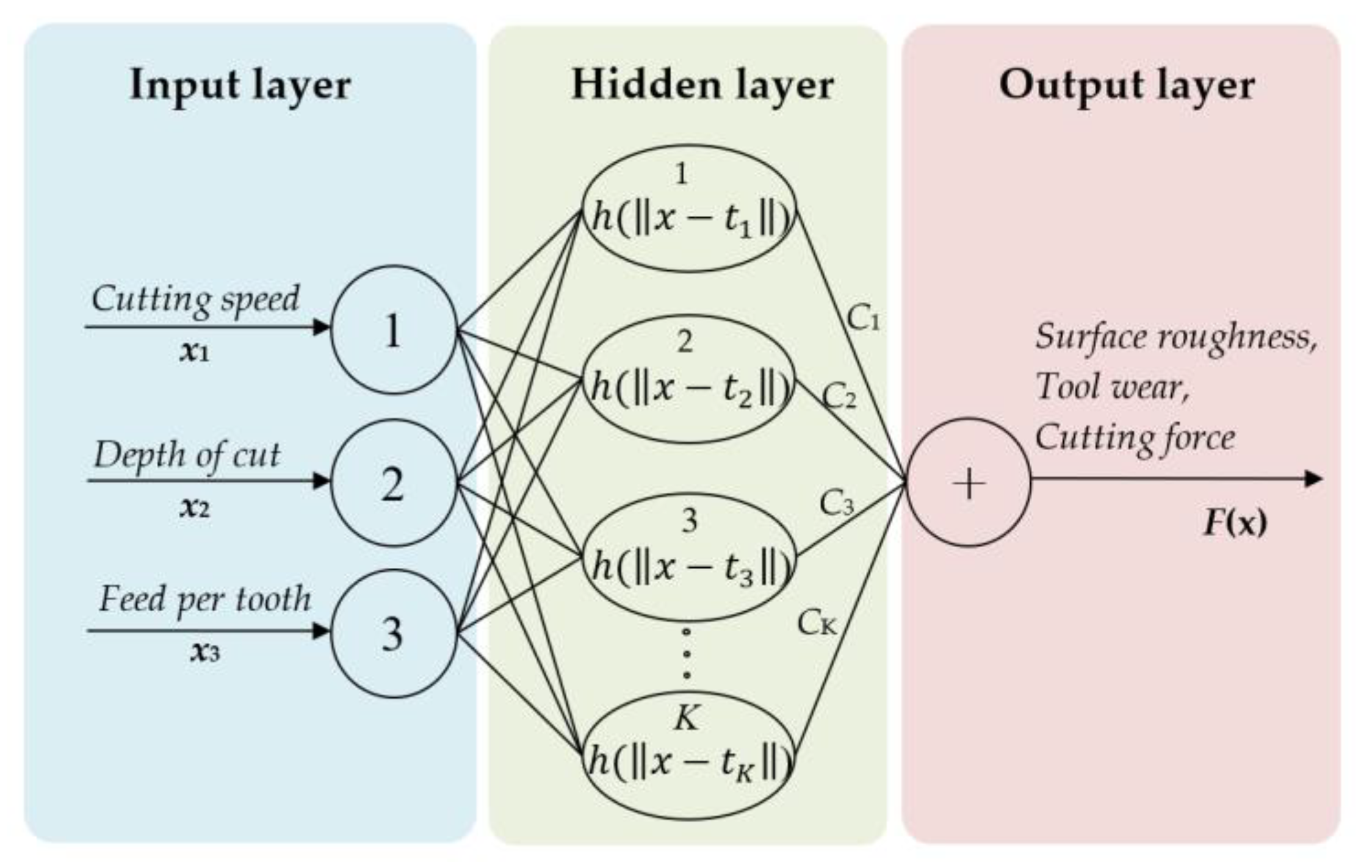
x represents n-dimensional input vectors, as regression coefficients.
-
xi represents n-dimensional vectors of the position of the point-of-learning dataset.
-
ci represents the unknown interpolation coefficient.
-
h(.) represents the radial basis function.
-
‖.‖ represents the Euclidean distance in multi-dimensional real space Rn.
-
N represents the number of interpolation points.
The Gaussian function is used as a radial basis function in the common implementation of the RBF network.
For cases where the learning dataset is ordinarily weighted with some noise, researchers have shown that approximation gives better results than interpolation. Namely, it is expected to filter the noise by means of approximation, in contrast to interpolation where the hyper-plane passes exactly through all points of the learning dataset. Therefore, it seems that it is not necessary to compute the distance of all N points of the learning data set. Therefore, Broomhead and Lowe [49] suggested selecting K points (called the centre), where K < N. Now, Equation (5) has the form:
F ( x ) = j = 1 K c j h ( x t j )
where:
-
tj represents n-dimensional vectors of the centre of the radial basis function.
-
K represents the index of the neuron of the hidden layer.
With the assumption that the number of centres K is less than the number of points N, the number and position of the centres of the neurons of the hidden layers have been determined in the learning procedure. Then, Euclidean distances of the input vector have been calculated for the neurons of the hidden layer h (‖xi − tj‖). In this way, a rectangular matrix (NxX) of the values of the hidden layer has been computed (H)ij = h (‖xi − tj‖). The implementation of N interpolation conditions leads to a system of N linear equations with K unknown terms. Following that, the optimal solution has been calculated with a pseudo inversion of the matrix H. The final solution represents the approximation of the multivariable function. Since the radial basis neural network (RBNN) models are simple to use and implement, at the same time showing very good learning abilities and generalization abilities, they are very often used in different research studies and in industrial practice.
The RBNN model used for predicting the output of the three-variable function f(x), x = [x1,x2,x3]T, is shown in Figure 8.
The same model was used in this research. Generally, the RBF network consists of three completely different layers. The input layer, in this case, consists of three neurons, and the output layer consists of one neuron. The number of neurons in the hidden layer is equal to the number of K centres.
Five physical variables, namely, Ra, VB, Fx, Fy and Fz, were modelled using the above-mentioned network architecture. Firstly, the training was completed, and then the testing was performed in order to check the generalization ability. Tests were conducted with the new set of data. For both training and testing, MATALB’s neural network toolbox was used [50].

3. Results

The measured values of Ra, VB, Fx, Fy and Fz, obtained by 30 experiments for hard milling under CCAC conditions are presented in Table 6. Similar tables for hard milling under CFs and dry machining conditions can be found in the Supplementary Materials.
For the verification and testing of both RA and RBNN models, 10 additional experiments were conducted. The input parameters and measured values of those additional experiments are presented in Table 7.
A metallographic examination of the samples, hard machined in three different cutting conditions, was performed. The metallography of certain samples is given in Figure 9.

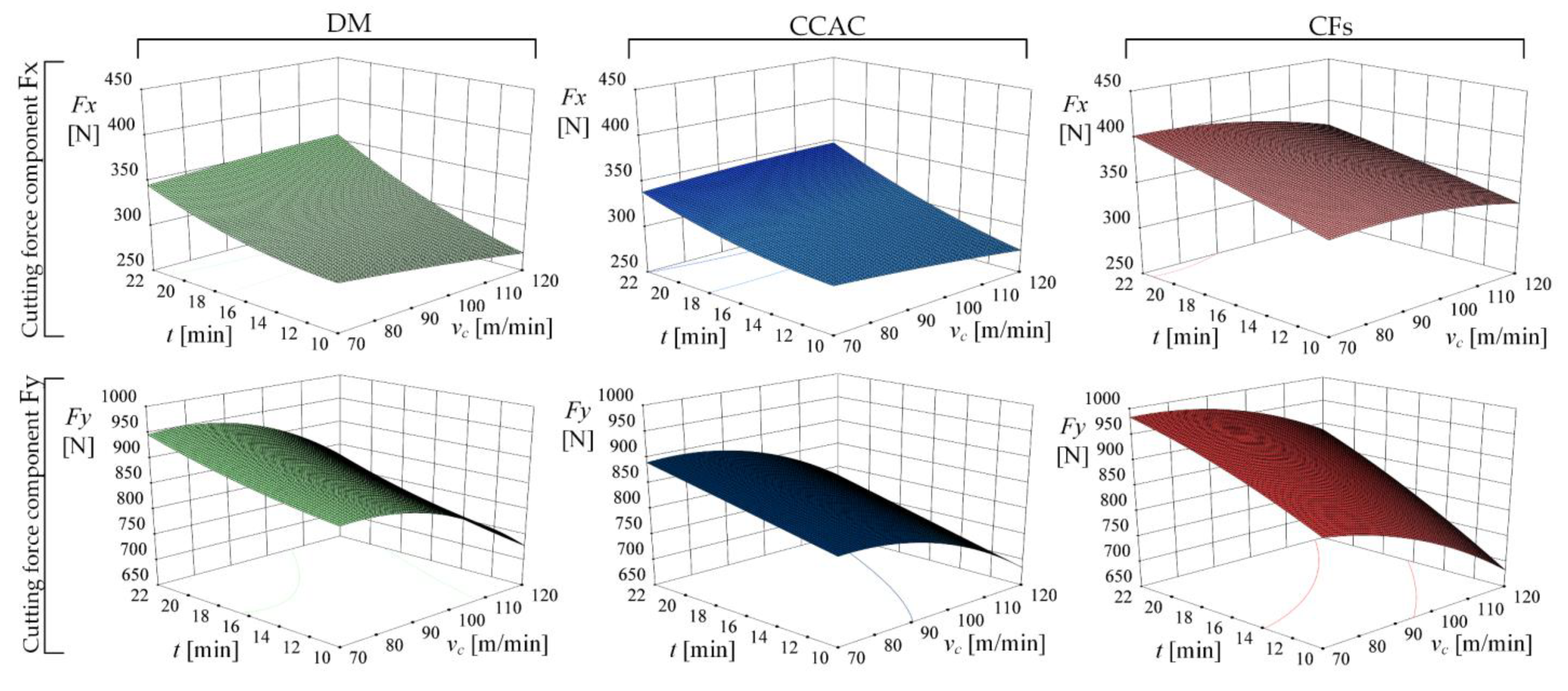
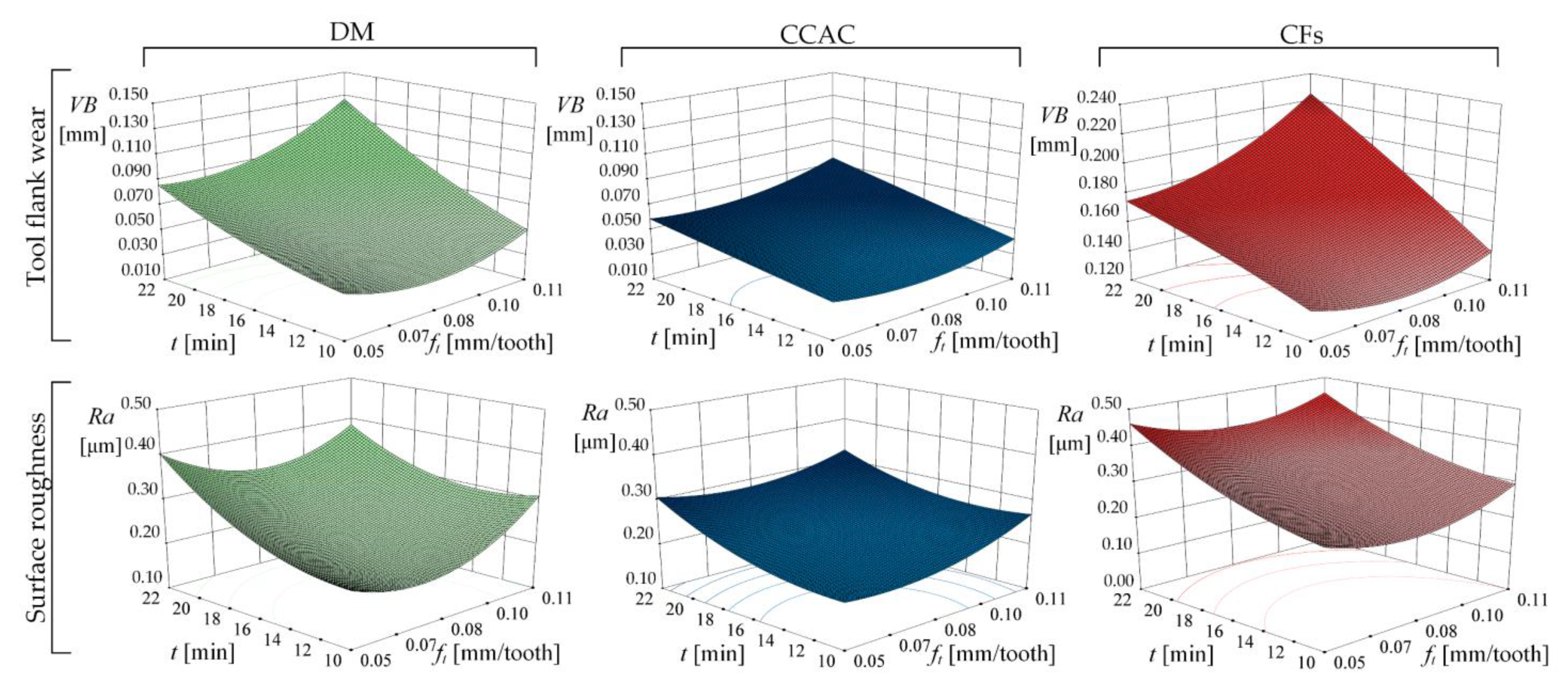
3.1. Parametric Analysis of the Influence of Input Variables on the Milling Force Components, Tool Wear and Surface Roughness

By applying regression analysis, the coefficients of regression, multi-regression factors, standard false evaluation and the value of the t-test were assessed. After omitting insignificant factors, the mathematical models for the components of cutting force Fx, Fy, Fz, surface roughness Ra and tool wear VB were obtained. The obtained models enabled the implementation of numerical simulations in which certain important input parameters were varied in order to analyse the influence of certain parameters on the output values of the process. The cutting speed (vc), feed per tooth (ft) and machining time (t) were selected as significant input parameters.
Analysis of the influence of the radial depth of the cut (ae) showed a very small influence of the same on the selected output sizes compared to other processing parameters. The depth of the cut in general has no direct influence on the surface roughness because the height and form of the roughness profile are not dependent on the depth of the cut. The same applies to tool wear where the influence of the cutting depth on it is minimal. However, it is worth mentioning the phenomenon explained by the theory of dislocation, showing the depth of cut is inversely proportional in relation to the tool wear, i.e., by increasing the depth of cut, the tool wear decreases. Accordingly, the radial depth of the cut will not be considered during further analysis, i.e., a constant value of 1.5 mm was assumed. Furthermore, the component of the milling force Fz, due to its small values compared to the components Fx and Fy, was not taken into consideration.
Figure 10 shows the change in the value of cutting force components depending on the change in cutting speed and machining time for the hard milling process.
As the cutting speed increases, the cutting force decreases. A higher cutting speed at a constant feed per tooth presupposes a smaller amount of material removal for one revolution of the tool, which is reflected in the smaller value of the force components Fx and Fy. An increase in the values of Fx and Fy despite an increase in the cutting speed appears after a certain duration of machining as a result of tool wear.
Figure 11 shows the change in the value of the tool flank wear and surface roughness depending on the change in feed per tooth and machining time when hard milling with a constant cutting speed and radial depth of cut.
During hard milling, the high temperatures generated in the cutting zone at higher feeds reduce the strength and hardness of the tool material, which enables the occurrence of different types of wear. In this case, the application of CCAC with the associated low coolant (airflow) temperature is of great importance. The cooling effect of CCAC can be attributed to the reduction of temperature in the cutting zone, which contributes to the reduction of abrasive wear by maintaining the hardness of the tool material, and to the reduction of heat-induced adhesive and diffusion wear, as shown in Figure 12. Machining time has the highest impact on the value of surface roughness, followed by the feed per tooth. Figure 13 shows the wear of the tool flank face and the roughness of the machined surface during hard milling in different machining conditions correlated with the volume of the removed material (V). The total volume of removed material V [mm3] was calculated using the value of the material removal rate (MRR) as follows:
V = M R R × t
For the milling process, MRR [mm3/min], as shown in Figure 7, is calculated with the following equation:
M R R = a p a e f t n N
where N represents the number of cutting inserts.

3.2. RA and RBNN Models Simulation

The testing and training results of the RBNN model of flank tool wear for hard milling under CCAC are shown in Figure 14. The coefficient of determination of R2 = 0.9986 shows that the presented RBNN model is representative, and 99.86% of deviations were interpreted by the given model. The value of the predicted coefficient of determination Rpred2 of 0.9833 shows an outstanding ability to predict cutting tool flank wear using the presented RBNN model. For comparison, the values of the coefficient of determination and the predicted coefficient of determination of the RBNN model are higher than the same coefficients of the RA model (R2 = 0.9862; Rpred2 = 0.9559).
The results of predicting tool wear using the RA and RBNN models for hard milling under CCAC conditions are given in Table 8. A smaller average relative prediction error was achieved in the case of the RBNN model (3.92%). The higher average relative error of prediction of the RA model (4.38%) shows a weaker ability to predict tool wear compared to the prediction of the RBNN model.

3.3. Optimizing the Number and Type of Input Variables of RBNN in Order to Improve the Prediction Ability

Different RBNN models are formed considering different numbers and types (representing the input parameter) of input layer neurons. Table 9 presents 16 different RBNN models in addition to the RA model. The presented models are divided into three groups. The first group consists of models with four input sizes or four neurons in the input layer, the second with five neurons of the input layer, and the third group represents models with six or more neurons in the input layer. The number of hidden layer neurons depends on the number of training data and the number of input layer neurons. The position of the centre of the neuron of the hidden layer is fixed, and it is chosen by random selection. Since these are models intended for predicting tool wear, there is only one neuron in the output layer that represents the tool flank wear (VB).
Figure 15 shows the results of the comparison of tool wear prediction models divided into groups according to the number of input layer neurons for hard milling under CCAC conditions.
Following the presented results, the best cases for each of the three groups were selected, and detailed results of the tool wear prediction with relative errors are shown in Table 10.

4. Discussion

The results of tool wear during hard milling under the CF conditions showed higher wear values compared to DM and CCAC conditions, as shown in Figure 12. Such a phenomenon can be explained by looking at Figure 16, which shows the tool flank wear depending on the time of cutting insert engagement under CF conditions. The picture shows the wear of the TiAlN coating of the tool after 2 min of cutting insert engagement. The complexity of the interaction between the tool material, the workpiece material and the chemical composition of CFs at different temperatures and pressures caused a negative chemical reaction and sudden wear of the TiAlN coating layer. Evidence that it is the case of TiAlN coating wear rather than some of the expected wear mechanisms is shown in Figure 16. Regarding “Detail A”, the preserved cutting edge of the cutting insert above the wear area of the TiAlN coating is clearly visible. A similar effect appeared in the study of Siow et al. [51] while hard milling under flood lubrication. In the initial stage of machining, the coating at the tool centre was delaminated, exposing the carbide substrate to attrition wear. The result of that was the formation of cavities, which was followed by cracking and fracture.
In this study, the same type of initial wear was observed after the first wear measurements of the tool flank wear in all hard milling experiments under CF conditions. These data point to the conclusion that the chemical composition of the emulsion, the temperature of the emulsion, the flow and the method of application used do not satisfy the requirements of the workpiece material and cutting tool materials and coatings used in this study. Certain characteristics of the CF used are given in Table 4; however, the detailed chemical composition remains unknown. Regarding the significant influence on the tool flank wear, characterisation of CF Rhenus TU30 T requires a detailed analysis and can be considered a possible topic of further research.
Despite the increase in the duration of the cutting insert engagement, hard milling under the conditions of CCAC shows the stability of the cutting tool throughout all experiments, as shown in Figure 12. The trend of increase in the surface roughness due to the increase in cutting insert engagement duration is approximately the same for DM and CCAC cutting conditions. However, cooling with low-temperature air prevents the negative impact of generated heat in the cutting zone resulting from high feed values. Part of the generated heat that passes into the workpiece via conduction tends to create thermal cracks on the processed surface [52]. The formed cracks are manifested in the deterioration of the quality or increase in the roughness of the treated surface, especially in the case of dry machining. The roughness of the machined surface under CF conditions cannot be taken into consideration because high roughness values are the result of catastrophic tool wear, the causes of which have been previously explained. Overall, the poor machinability of hard milling under CF conditions in terms of the high value of tool wear and surface roughness is greatly influenced by the material and the properties of the workpiece together with the cutting tool coating. As mentioned in a previous study by Beake et al. [53], tool performance is strongly correlated to the micro-mechanical properties of the coatings. Following that, the importance of choosing the right cutting insert coating when performing hard milling is crucial. Failing to do so can end up in experiencing a tool lifetime two times shorter than expected, which proved to be the case in this study.
As expected, the tool flank wear has a constant tendency to increase with cutting time, as shown in Figure 13a. Of the input parameters, cutting speed has the greatest influence on tool wear, while the feed per tooth has a slightly smaller influence when compared to the cutting speed. Figure 13a presents the tool durability for machining under different cutting conditions when using the cutting parameters of experiment number 4, as seen in Table 5. The durability of the cutting tool, T [min], was calculated regarding the time in which the cutting tool reached the value of critical flank wear of VBcritical 0.15 mm. This particular value was adopted after performing preliminary experiments and obtaining results that indicated a sudden increase in the value of cutting force components and surface roughness when the tool flank wear reaches the critical value of 0.15 m. The average tool durability for hard milling under CCAC showed an increase of 26% compared to DM. The cutting tool under the conditions of CCAC proved to be more than two times more durable than the same tool used for hard milling under CF conditions. The reason for such a huge difference lies in the effect of choosing the wrong PVD coating, as already explained and presented in the results of previous studies [53].
When measuring the surface roughness, the smallest impact of a change in input parameters on the Ra value was recorded for CCAC conditions. The values achieved during hard milling under CCAC ranged from Ra = 0.2 ÷ 0.4 µm, with an average value of Ra = 0.28 µm (median M = 0.26), which corresponds to roughness classes N4 and N5. Such surface roughness results are comparable to those obtained in grinding procedures, so in this case, the use of hard milling can be considered technologically justified. An examination of the metallographic images revealed that no white layer appeared in any experiment, which confirms that the processing parameters and tool wear criterion were correctly selected.
All the positive results of hard milling under the CCAC conditions presented in this study are confirmation that such a technique covers all aspects of sustainability and fulfils all the conditions of sustainable manufacturing.
The methods and testing of tool wear prediction with the RA and RBNN models point to the advantages of the neural network method and the associated RBNN model. The advantages are manifested in a more faithful description of the actual wearing process, which is clearly visible from the graphic display when comparing both response surface models, as shown in Figure 17. In addition, better prediction of tool wear was observed for RBNN with a total average relative error of 3.92% determined by testing the results of additional experiments that were not used in the formation of the model. As proven from previously conducted studies [54], a smaller relative average prediction error indicates the good ability of the RBNN model when predicting tool flank wear.
In order to further improve the prediction ability of the presented RBNN model, the optimisation of the number and type of input layer neurons was conducted. The comparison of tool wear prediction models divided into groups according to the number of input layer neurons for hard milling under CCAC conditions, as presented in Figure 15, highlights one model from each group with the best prediction result. Following those results, the three best models were compared pointing out RBNN 16 as the most precise model when predicting the tool flank wear. However, a possible disadvantage of the RBNN16 model is the longer data processing time, which can have the effect of a delayed reaction when there is a need for an instant change of the worn tool. In that case, other models with a smaller number of input layer neurons should be considered, such as RBNN7 and RBNN 1. It is worth mentioning that the RBNN 2 model with a relative prediction error of 3.97%, just 0.05% higher than that of RBNN1, also presents a possible optimal solution in this case. The reason for that is the type of input layer neurons of RBNN2, namely, Fx, Fy, Fz and t, makes it ideal for the creation of an on-line tool condition monitoring system, which would be a huge step towards smart manufacturing. The main task of such a system would be the real-time processing of the obtained information collected by the piezoelectric dynamometer for measuring the cutting force components, as shown in Figure 6, and using the RBNN model when deciding on the timely replacement of the tool considering predicted tool flank wear. Since neural networks have been proven to be fast and reliable algorithms in different everyday applications such as face recognition or language translation [55], in the same way, they could be used during ongoing machining processes to predict any machining parameter based on live data collection.
Future research directions lay within developing the monitoring system using the presented RBNN model together with an investigation of the machine tool system’s energy consumption for different machining conditions (DM, CFs and CCAC) and the possibilities of increasing its efficiency by using Digital Twin technologies.

5. Conclusions

It has become essential in modern manufacturing industries to ensure higher productivity and product quality while embracing industry 4.0/5.0 technologies. In this study, extensive experimental research was conducted on the machining process in the form of hard milling under different cutting conditions, namely, CCAC, DM and CFs. The efficiency of the process was evaluated by measuring variables such as Ra, VB and three orthogonal cutting force components, Fx, Fy and Fz. Based on detailed and extensive experiments, the following conclusions can be drawn from the presented study:
  • The CCAC technique fulfils functional aspects and all the sustainability aspects as an alternative type of cooling within the machining process, while not having any serious drawbacks.
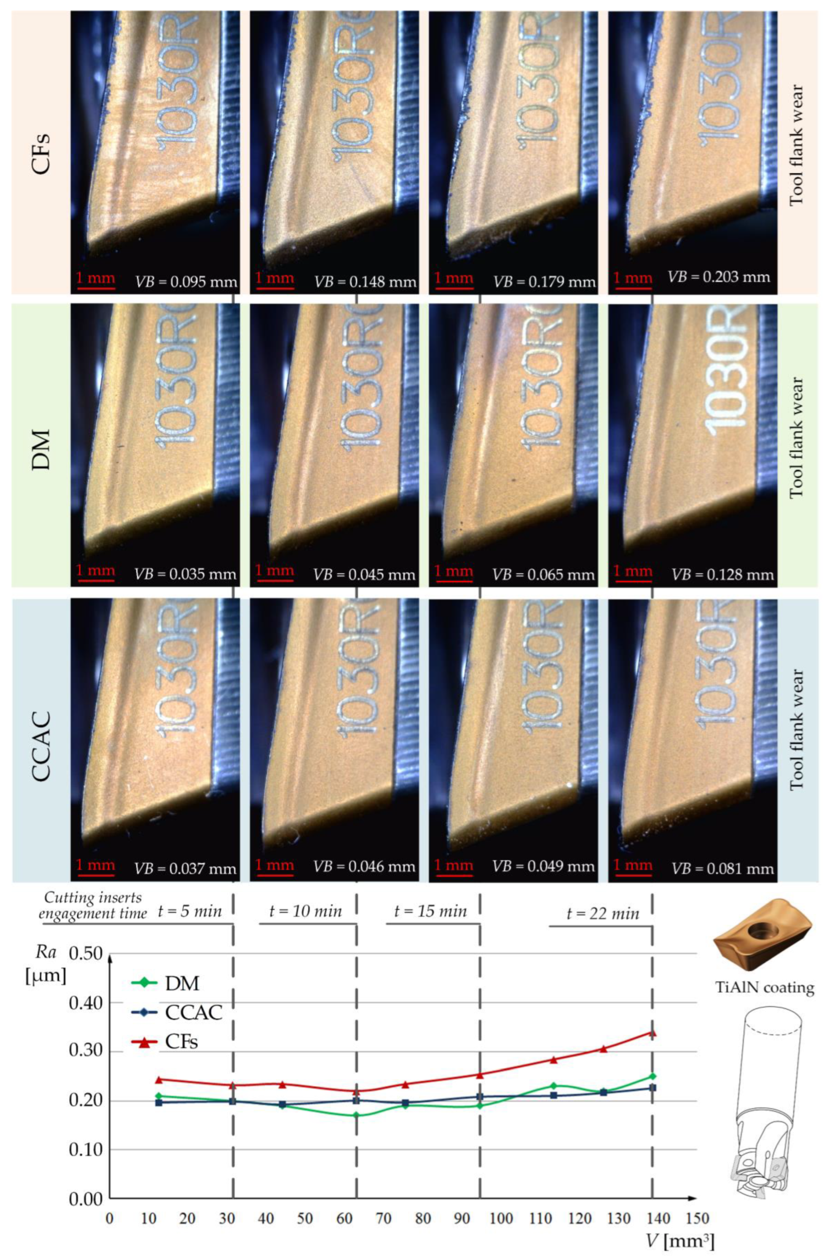
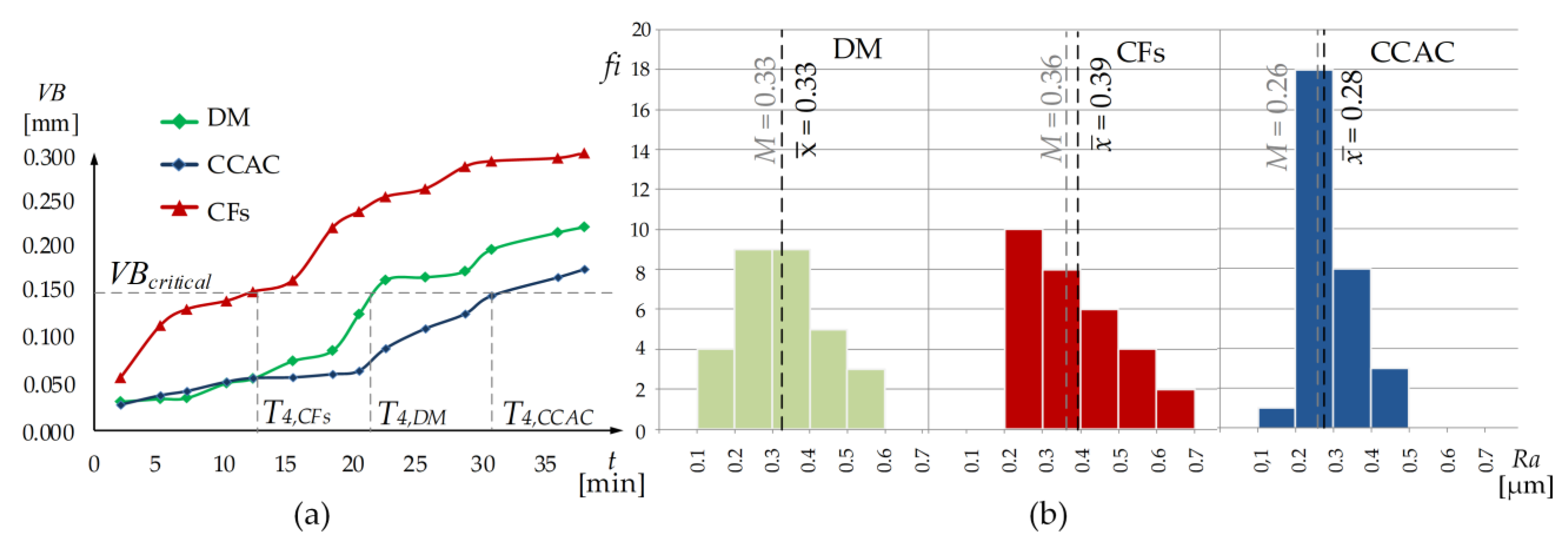
  • The lowest average tool flank wear of 0.05 mm was achieved when hard milling under CCAC cutting conditions, followed by DM with an average VB value of 0.08 mm and CFs with an average VB value of 0.17 mm.
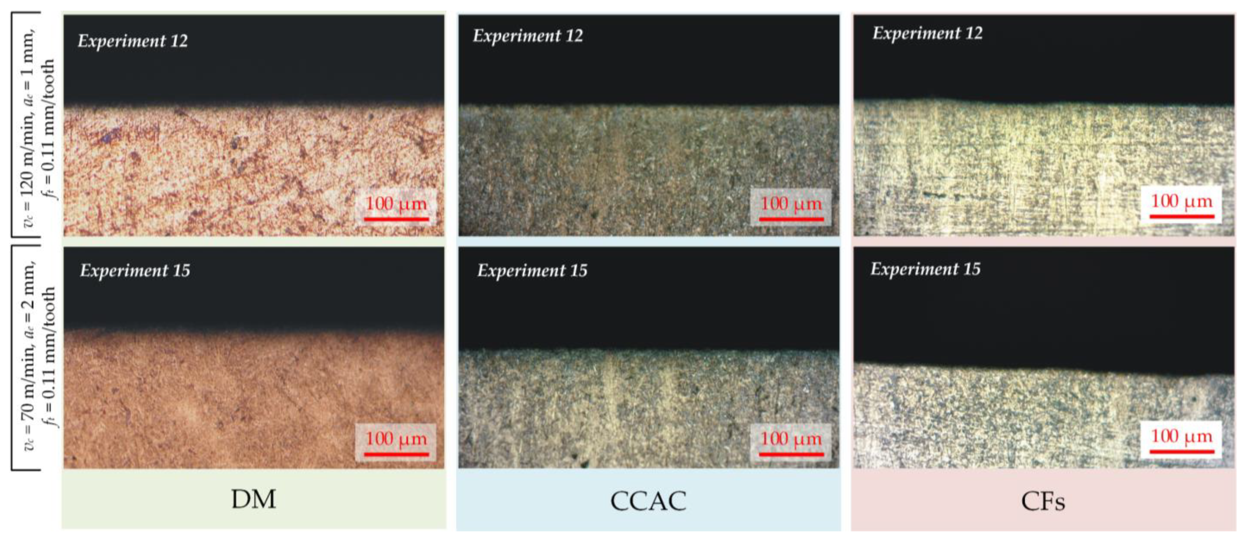
  • The technological justification of the CCAC technique was achieved as a result of the lowest measured surface roughness compared to DM and CFs. The surface roughness value measured during hard milling under CCAC with an average of Ra = 0.28 µm corresponds to roughness classes N4 and N5, which are comparable to those obtained in grinding procedures.
  • The average tool durability for hard milling under CCAC showed an increase of 26% compared to DM. Tool durability proved to be more than two times lower in the case of hard milling under the CFs condition.
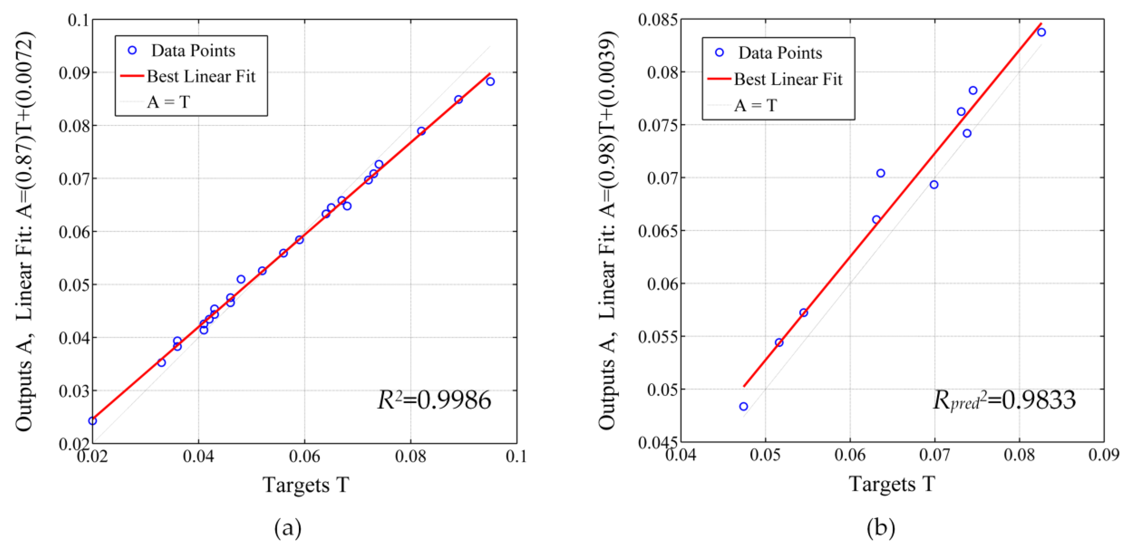
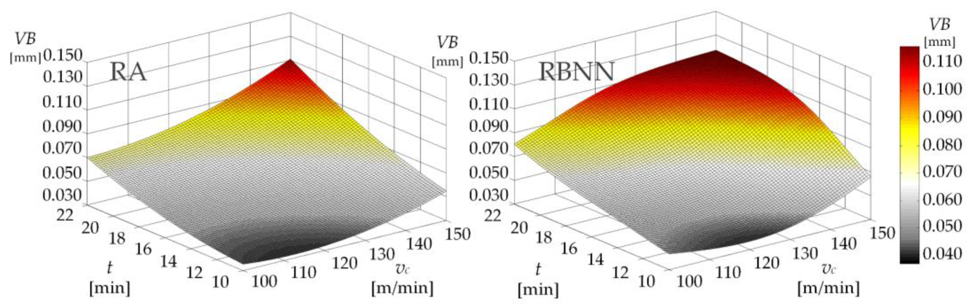
  • The proposed RBNN model can be utilized for tool flank wear prediction with better accuracy compared to the RA model.
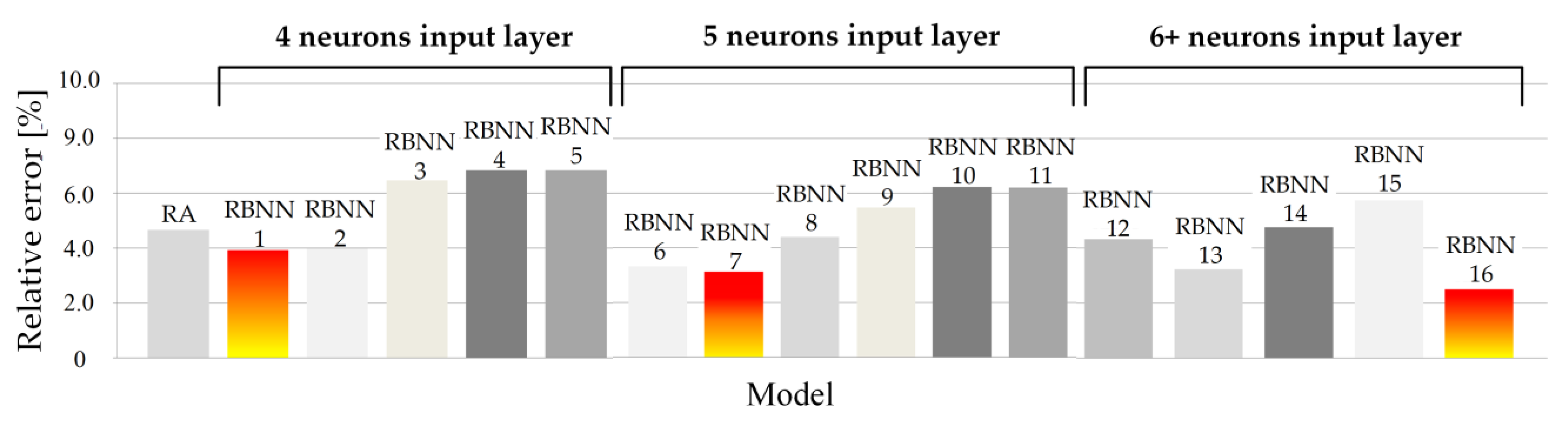
  • Optimisation of the number and type of input layer neurons resulted in choosing RBNN 2 with four input layer neurons (Fx, Fy, Fz and t) and a relative prediction error of 3.97% as the optimal choice for the creation of a future on-line tool condition monitoring system as part of the Industry 4.0/5.0 paradigm.
  • The CCAC technique using a vortex tube for hard milling was proven to be an efficient and sustainable solution for smart manufacturing.

Supplementary Materials

The following supporting information can be downloaded at: https://www.mdpi.com/article/10.3390/machines11020264/s1, Hard milling_CCAC_CFs_DM_Experimental results.pdf.

Author Contributions

Conceptualization, L.C. and M.M.; methodology, L.C., D.B. and S.J.; software, L.C. and S.J.; validation, L.C., S.J. and M.M.; formal analysis, L.C., D.B. and S.J.; investigation, L.C. and M.M.; resources, D.B. and S.J.; data curation, L.C. and S.J.; writing—original draft preparation, L.C. and M.M.; writing—review and editing, L.C., D.B., S.J. and M.M.; visualization, L.C.; supervision, D.B. and S.J. All authors have read and agreed to the published version of the manuscript.

Funding

This research was funded by MZOS 023-0692976-1742 project.

Data Availability Statement

The data presented in this study are available in the Supplementary Material as Hard milling_CCAC_CFs_DM_Experimental results.pdf.

Acknowledgments

Experimental datasets used in this research are from Luka Celent’s doctoral dissertation, which was part of the MZOS 023-0692976-1742 research project.

Conflicts of Interest

The authors declare no conflict of interest.

References

  1. Koren, Y. The Global Manufacturing Revolution: Product-Process-Business Integration and Reconfigurable Systems; Wiley: Hoboken, NJ, USA, 2010. [Google Scholar]
  2. Yang, M.; Wang, E.Z.; Hou, Y. The relationship between manufacturing growth and CO2 emissions: Does renewable energy consumption matter? Energy 2021, 232, 121032. [Google Scholar] [CrossRef]
  3. Cantore, N.; Clara, M.; Lavopa, A.; Soare, C. Manufacturing as an engine of growth: Which is the best fuel? Struct. Chang. Econ. Dyn. 2017, 42, 56–66. [Google Scholar] [CrossRef]
  4. Groover, M.P. Introduction to Manufacturing Processes; Wiley: Hoboken, NJ, USA, 2011. [Google Scholar]
  5. Tian, P.; He, L.; Zhou, T.; Du, F.; Zou, Z.; Zhou, X.; Jiang, H. Effect of workpiece microstructure on tool wear behavior and surface quality during machining Inconel 718 alloy. Tribol. Int. 2022, 175, 107814. [Google Scholar] [CrossRef]
  6. Benedicto, E.; Carou, D.; Rubio, E.M. Technical, Economic and Environmental Review of the Lubrication/Cooling Systems Used in Machining Processes. Procedia Eng. 2017, 184, 99–116. [Google Scholar] [CrossRef]
  7. Lawal, S.A.; Choudhury, I.A.; Nukman, Y. Application of vegetable oil-based metalworking fluids in machining ferrous metals—A review. Int. J. Mach. Tools Manuf. 2012, 52, 1–12. [Google Scholar] [CrossRef]
  8. Debnath, S.; Reddy, M.M.; Yi, Q.S. Environmental friendly cutting fluids and cooling techniques in machining: A review. J. Clean. Prod. 2014, 83, 33–47. [Google Scholar] [CrossRef]
  9. Winter, M.; Bock, R.; Herrmann, C. Investigation of a new polymer-water based cutting fluid to substitute mineral oil based fluids in grinding processes. CIRP J. Manuf. Sci. Technol. 2013, 6, 254–262. [Google Scholar] [CrossRef]
  10. Davim, J.P. Green Manufacturing Processes and Systems; Springer-Verlag Berlin Heidelberg: Berlin/Heidelberg, Germany, 2013. [Google Scholar] [CrossRef]
  11. Young, P.; Byrne, G.; Cotterell, M. Manufacturing and the environment. Int. J. Adv. Manuf. Technol. 1997, 13, 488–493. [Google Scholar] [CrossRef]
  12. The National Institute for Occupational Safety and Health (NIOSH). Metalworking Fluids. Available online: https://www.cdc.gov/niosh/topics/metalworking/default.html#print (accessed on 20 January 2023).
  13. Henriks-Eckerman, M.-L.; Suuronen, K.; Jolanki, R. Analysis of allergens in metalworking fluids. Contact Dermat. 2008, 59, 261–267. [Google Scholar] [CrossRef] [PubMed]
  14. Hannu, T.; Suuronen, K.; Aalto-Korte, K.; Alanko, K.; Luukkonen, R.; Järvelä, M.; Jolanki, R.; Jaakkola, M.S. Occupational respiratory and skin diseases among Finnish machinists: Findings of a large clinical study. Int. Arch. Occup. Environ. Health 2013, 86, 189–197. [Google Scholar] [CrossRef] [PubMed]
  15. Haider, J.; Hashmi, M.S.J. Health and Environmental Impacts in Metal Machining Processes; Hashmi, S., Batalha, G.F., van Tyne, C.J., Yilbas, B.B.T.-C.M.P., Eds.; Elsevier: Oxford, UK, 2014; pp. 7–33. [Google Scholar] [CrossRef]
  16. Dixit, J.P.; Sarma, U.S.; Davim, D.K. Environmentally Friendly Machining; Springer: New York, NY, USA, 2012. [Google Scholar] [CrossRef]
  17. Katna, R.; Suhaib, M.; Agrawal, N. Nonedible vegetable oil-based cutting fluids for machining processes—A review. Mater. Manuf. Process. 2020, 35, 1–32. [Google Scholar] [CrossRef]
  18. Pusavec, F.; Kramar, D.; Krajnik, P.; Kopac, J. Transitioning to sustainable production—Part II: Evaluation of sustainable machining technologies. J. Clean. Prod. 2010, 18, 1211–1221. [Google Scholar] [CrossRef]
  19. Haldar, B.; Joardar, H.; Louhichi, B.; Alsaleh, N.A.; Alfozan, A. A Comparative Machinability Study of SS 304 in Turning under Dry, New Micro-Jet, and Flood Cooling Lubrication Conditions. Lubricants 2022, 10, 359. [Google Scholar] [CrossRef]
  20. Jing, L.; Chen, M.; An, Q. Study on Performance of PVD AlTiN Coatings and AlTiN-Based Composite Coatings in Dry End Milling of Hardened Steel SKD11. Metals 2021, 11, 2019. [Google Scholar] [CrossRef]
  21. Fratila, D. Environmentally friendly Manufacturing Processes in the Context of Transition to Sustainable Production. Compr. Mater. Process. 2014, 8, 163–175. [Google Scholar] [CrossRef]
  22. Jahaziel, R.B.; Krishnaraj, V.; Sudhagar, S.; Priyadarshini, B.G. Improving dry machining performance of surface modified cutting tools through combined effect of texture and TiN-WS2 coating. J. Manuf. Process. 2023, 85, 101–108. [Google Scholar] [CrossRef]
  23. Astakhov, V.P. Ecological Machining: Near-dry Machining BT-Machining: Fundamentals and Recent Advances. In Machining; Davim, J.P., Ed.; Springer: London, UK, 2008; pp. 195–223. [Google Scholar] [CrossRef]
  24. Aslan, A.; Salur, E.; Kuntoğlu, M. Evaluation of the Role of Dry and MQL Regimes on Machining and Sustainability Index of Strenx 900 Steel. Lubricants 2022, 10, 301. [Google Scholar] [CrossRef]
  25. Sen, B.; Mia, M.; Krolczyk, G.M.; Mandal, U.K.; Mondal, S.P. Eco-Friendly Cutting Fluids in Minimum Quantity Lubrication Assisted Machining: A Review on the Perception of Sustainable Manufacturing. Int. J. Precis. Eng. Manuf. Technol. 2021, 8, 249–280. [Google Scholar] [CrossRef]
  26. Khanna, C.; Agrawal, N. Titanium Machining Using Indigenously Developed Sustainable Cryogenic Machining Facility. In Materials Forming, Machining and Post Processing; Springer: Berlin/Heidelberg, Germany, 2020. [Google Scholar] [CrossRef]
  27. Hegab, H.; Damir, A.; Attia, H. Sustainable machining of Ti-6Al-4V using cryogenic cooling: An optimized approach. Procedia CIRP 2020, 101, 346–349. [Google Scholar] [CrossRef]
  28. Pusavec, F.; Deshpande, A.; Yang, S.; M Saoubi, R.; Kopac, J.; Dillon, O.W., Jr.; Jawahir, I.S. Sustainable machining of high temperature Nickel alloy—Inconel 718: Part 1—Predictive performance models. J. Clean. Prod. 2014, 81, 255–269. [Google Scholar] [CrossRef]
  29. Cagan, S.C.; Buldum, B.B. Chapter 10—Cryogenic cooling-based sustainable machining. In Handbooks in Advanced Manufacturing—Sustainable Manufacturing; Gupta, K., Salonitis, K.B.T.-S.M., Eds.; Elsevier: Amsterdam, Netherland, 2021; pp. 259–285. [Google Scholar] [CrossRef]
  30. Sharma, V.S.; Dogra, M.; Suri, N.M. Cooling techniques for improved productivity in turning. Int. J. Mach. Tools Manuf. 2009, 49, 435–453. [Google Scholar] [CrossRef]
  31. Su, Y.; He, N.; Li, L.; Iqbal, A.; Xiao, M.H.; Xu, S.; Qiu, B.G. Refrigerated cooling air cutting of difficult-to-cut materials. Int. J. Mach. Tools Manuf. 2007, 47, 927–933. [Google Scholar] [CrossRef]
  32. Swain, S.; Patra, S.K.; Roul, M.K.; Sahoo, L.K. A short review on cooling process using compressed cold air by vortex tube in machining. Mater. Today Proc. 2022, 64, 382–389. [Google Scholar] [CrossRef]
  33. Saikiran, M.; Ravali, G.; Kumar, P. Comparative study of vegetable based and conventional cutting fluids in machining of copper alloys. Mater. Today Proc. 2019, 19, 611–614. [Google Scholar] [CrossRef]
  34. García-Martínez, E.; Miguel, V.; Martínez-Martínez, A.; Manjabacas, M.C.; Coello, J. Sustainable Lubrication Methods for the Machining of Titanium Alloys: An Overview. Materials 2019, 12, 3852. [Google Scholar] [CrossRef]
  35. Afonso, I.S.; Pereira, J.; Ribeiro, A.E.; Amaral, J.S.; Rodrigues, N.; Gomes, J.R.; Lima, R.; Ribeiro, J. Analysis of a Vegetable Oil Performance in a Milling Process by MQL Lubrication. Micromachines 2022, 13, 1254. [Google Scholar] [CrossRef]
  36. Gajrani, K.K.; Sankar, M.R. Past and Current Status of Eco-Friendly Vegetable Oil Based Metal Cutting Fluids. Mater. Today Proc. 2017, 4, 3786–3795. [Google Scholar] [CrossRef]
  37. Sharma, A.; Kumar, R. Potential use of minimum quantity lubrication (MQL) in machining of biocompatible materials using environment friendly cutting fluids: An overview. Mater. Today Proc. 2021, 45, 5315–5319. [Google Scholar] [CrossRef]
  38. Pandey, K.; Datta, S. Chapter Eight—Machinability study of Inconel 825 superalloy under nanofluid MQL: Application of sunflower oil as a base cutting fluid with MWCNTs and nano-Al2O3 as additives. In Woodhead Publishing Reviews: Mechanical Engineering Series, Sustainable Manufacturing and Design; Palanikumar, K., Natarajan, E., Ramesh, S., Davim, J.P., Eds.; Woodhead Publishing: Cambridge, UK, 2021; pp. 151–197. [Google Scholar] [CrossRef]
  39. Nobrega, G.; de Souza, R.R.; Gonçalves, I.M.; Moita, A.S.; Ribeiro, J.E.; Lima, R.A. Recent Developments on the Thermal Properties, Stability and Applications of Nanofluids in Machining, Solar Energy and Biomedicine. Appl. Sci. 2022, 12, 1115. [Google Scholar] [CrossRef]
  40. Esfe, M.H.; Bahiraei, M.; Mir, A. Application of conventional and hybrid nanofluids in different machining processes: A critical review. Adv. Colloid Interface Sci. 2020, 282, 102199. [Google Scholar] [CrossRef]
  41. Kagermann, J.; Wahlster, H.; Helbig, W. Recommendations for Implementing the Strategic Initiative Industrie 4.0; Woodhead Publishing: Cambridge, UK, 2013; pp. 151–197. [Google Scholar]
  42. Renda, D.; Serger, A.S.; Tataj, S.; Hidalgo, D.; Giovannini, C.; Huang, E.; Isaksson, A. Industry 5.0, a transformative vision for Europe; Publications Office of the European Union: Luxembourg, 2022; p. 30. [Google Scholar]
  43. Gartner Inc. Smart Manufacturing. Gart. Gloss. 2022. Available online: https://www.gartner.com/en/information-technology/glossary/smart-manufacturing (accessed on 14 December 2022).
  44. Celent, L.; Mladineo, M.; Gjeldum, N.; Zizic, M.C. Multi-Criteria Decision Support System for Smart and Sustainable Machining Process. Energies 2022, 15, 772. [Google Scholar] [CrossRef]
  45. Rajbongshi, S.K.; Sarma, D.K.; Singh, M.A. A Brief Review of White Layer Formation in Hard Machining with a Case Study; Springer: Singapore, 2020. [Google Scholar] [CrossRef]
  46. Xing, Q.; Zhang, J.; Qian, M.; Jia, Z.; Sun, B. Design, calibration and error analysis of a piezoelectric thrust dynamometer for small thrust liquid pulsed rocket engines. Meas. J. Int. Meas. Confed. 2011, 44, 338–344. [Google Scholar] [CrossRef]
  47. Zhang, J.; Shao, J.; Ren, Z.; Wang, B.; Shao, H.; Jia, Z. Research on dimension coupling of piezoelectric three-component force unit based on sensor assembly error. Adv. Mech. Eng. 2019, 11, 168781401984629. [Google Scholar] [CrossRef]
  48. Montgomery, D.C. Design and Analysis of Experiments, 9th ed.; Wiley: Hoboken, NJ, USA, 2013. [Google Scholar]
  49. Broomhead, D.; Lowe, D.S. Multivariable Functional Interpolation and Adaptive Networks. Complex Syst. 1988, 2, 321–355. [Google Scholar]
  50. Howard, D.; Mark, B. Neural Network Toolbox User’s Guide; The MathWorks: Natick, MA, USA, 2004. [Google Scholar]
  51. Siow, P.C.; Dayou, S.; Hsien, W.L.Y. Investigation of the tool wear and surface finish in low-speed milling of stainless steel under flood and mist lubrication. Mach. Sci. Technol. 2011, 15, 284–305. [Google Scholar] [CrossRef]
  52. Kalpakjian, S.; Schmid, S. Manufacturing Engineering and Technology, 7th ed.; Pearson: Singapore, 2014. [Google Scholar]
  53. Beake, B.D.; Ning, L.; Gey, C.; Veldhuis, S.C.; Kornberg, A.B.; Weaver, A.; Khanna, M.; Fox-Rabinovich, G.S. Wear performance of different PVD coatings during hard wet end milling of H13 tool steel. Surf. Coat. Technol. 2015, 279, 118–125. [Google Scholar] [CrossRef]
  54. Bagga, P.J.; Chavda, B.; Modi, V.; Makhesana, M.A.; Patel, K.M. Indirect tool wear measurement and prediction using multi-sensor data fusion and neural network during machining. Mater. Today Proc. 2022, 56, 51–55. [Google Scholar] [CrossRef]
  55. Wang, X.; Zhang, W. Anti-occlusion face recognition algorithm based on a deep convolutional neural network. Comput. Electr. Eng. 2021, 96, 107461. [Google Scholar] [CrossRef]
Figure 1. Sustainability aspects using cutting fluids within the machining process with clear examples of some serious drawbacks of CF usage.
Machines 11 00264 g001
Figure 2. CCAC using vortex tube: (a) Vortex tube isometric view, (b) the schematic representation of vortex tube working principle, (c) Cold Air Gun using vortex tube technology, (d) application within machine tool for end milling process.
Machines 11 00264 g002
Figure 3. Sustainable Smart Manufacturing concept.
Machines 11 00264 g003
Figure 4. Experimental setup.
Machines 11 00264 g004
Figure 5. Application of CCAC: (a) Nozzle positions, (b) cold air flow regarding the cutting tool surfaces.
Machines 11 00264 g005
Figure 6. Experimental measurement and analysis equipment.
Machines 11 00264 g006
Figure 7. Cutting parameters and tool flank wear measurements in end milling process.
Machines 11 00264 g007
Figure 8. RBNN model.
Machines 11 00264 g008
Figure 9. Metallographic examination of the hard-machined samples under different cutting conditions for experiments 12 and 15.
Machines 11 00264 g009
Figure 10. Response surface for the milling force components as a function of cutting speed and machining time during hard milling under different machining conditions (ft = 0.05 mm/tooth, ae = 1.5 mm).
Machines 11 00264 g010
Figure 11. Response surface for the tool flank wear and surface roughness as a function of feed per tooth and machining time during hard milling under different machining conditions (vc = 125 m/min, ae = 1.5 mm).
Machines 11 00264 g011
Figure 12. The influence of machining time and feed per tooth on the flank tool wear and surface roughness during hard milling (vc = 125 m/min, ae = 1.5 mm).
Machines 11 00264 g012
Figure 13. Parametric analysis of the influence of input variables on the tool flank wear and surface roughness: (a) Tool durability T, vc = 120 m/min, ft = 0.11 mm/tooth, ae = 1 mm (b) histogram for surface roughness measurement frequencies for machining under different conditions.
Machines 11 00264 g013
Figure 14. RBNN model simulation: (a) Training, (b) testing.
Machines 11 00264 g014
Figure 15. The relative error of the flank tool wear prediction for different models (hard milling, CCAC).
Machines 11 00264 g015
Figure 16. Sudden wear of the TiAlN coating due to a negative chemical reaction under CF conditions and subsequent catastrophic wear of the tool flank surface (vc = 95 m/min, ft = 0.08 mm/tooth, ae = 2.5 mm).
Machines 11 00264 g016
Figure 17. RA and RBNN response surface models for the tool flank wear as a function of cutting speed and machining time during hard milling under conditions of CCAC (ft = 0.08 mm/tooth, ae = 1.5 mm).
Machines 11 00264 g017
Table 1. Comparison matrix of alternative types of cooling/lubrication techniques for machining processes.
Alternative Type of CoolingInvestment CostsApplication CostMaintenance NeedProcess EfficiencySustainability Aspects Fulfillment
EconomicEnvironmentalSocial
Micro-jet MQLHHHHMMM
Cryogenic cooling (CC)HHHHMMM
Compressed cold air cooling (CCAC)LLLMMHH
Vegetable based cutting nanofluidsMLMMLHH
L—low, M—moderate, H—high.
Table 2. The main differences between Industry 4.0 and Industry 5.0 (adapted from [42]).
DimensionIndustry 4.0Industry 5.0
TechnologyCentred around enhanced efficiency through digital connectivity and artificial intelligence dataEmphasises the impact of alternative modes of (technology) governance for sustainability and resilience data
Technology centred around the emergence of cyber-physical objectivesEmpowers workers through the use of digital devices, endorsing a human-centric approach to technology
EconomyAligned with optimisation of business models within existing capital market dynamics and economic models, i.e., ultimately directed at minimisation of costs and maximisation of profit for shareholdersEnsures a framework for an industry that combines competitiveness and sustainability, allowing industry to realize its potential as one of the pillars of transformation
EcologyNo focus on design and performance dimensions essential for systemic transformation and decoupling of resource and material use from negative environmental and climate impactBuilds transition pathways towards environmentally sustainable uses of technology
SocietyNo focus on design and performance dimensions essential for systemic transformation and decoupling of resource and material use from negative social impactsExpands the remit of a corporation’s responsibility to their whole value chains
Introduces indicators that show, for each industrial ecosystem, the progress achieved on the path to well-being, resilience and overall sustainability
Table 3. The chemical composition and mechanical properties of workpiece (steel 42CrMo4).
Chemical Composition
CSiMnPSCrNiMoCu
0.4300.2780.770.0180.0281.090.080.1850.08
Mechanical properties
Yield strength [MPa]Tensile strength [MPa]Elongation [%]Notch impact energy [J]Hardness [HRC]
1128122314.44235
Table 4. Technical data for cutting fluid Rhenus TU30 T.
ConcentrateEmulsion
viscosity 20 °C
(mm2/s)
Content of
mineral oil %
pH-value
5%
corrosion protection
(DIN 51360-2)
approx. 160approx. 189.44% (grade 0)
Table 5. Input variables with permissible ranges for hard milling experiments.
Cutting Speed
vc [m/Min]
Feed per Tooth
ft [mm/Tooth]
Radial Depth of Cut
ae [mm]
Machining Time
t [Min]
Machining Conditions
Mc
70–1200.02–0.051–210–22Dry Machining (DM)
Conventional cutting fluid (CFs)
Compressed cold air cooling (CCAC)
Table 6. Measured experimental data for hard milling under CCAC conditions.
Exp.
Number
Input VariablesOutput Variables
vc
[m/Min]
ft
[mm/Tooth]
ae
[mm]
t
[Min]
Fx
[N]
Fy
[N]
Fz
[N]
VB
[mm]
Ra
[µm]
1700.05110335.31789.8964.360.0330.20
21200.05110299.31650.4568.130.0420.22
3700.11110457.741025.8370.070.0410.37
41200.11110400.45894.5674.110.0520.26
5700.05210285.56816.9372.290.0410.22
61200.05210251.23705.5662.260.0460.25
7700.11210406.891036.9979.560.0360.33
81200.11210360.51903.5175.590.0460.20
9700.05122326.56845.6568.120.0590.33
101200.05122365.56704.5674.190.0650.41
11700.11122490.451123.1283.640.0730.46
121200.11122456.85975.6582.800.0890.38
13700.05222340.23905.6289.670.0560.26
141200.05222334.45845.5683.070.0670.32
15700.11222459.691055.10103.560.0640.31
161200.11222424.92975.65101.450.0820.23
17450.081.516380.151001.8968.450.0430.32
181450.081.516330.16734.5670.450.0720.26
19950.021.516280.56480.6561.530.0680.29
20950.141.516500.12910.4690.480.0950.39
21950.080.516401.23945.9368.950.0430.29
22950.082.516338.561056.4588.310.0360.17
23950.081.54316.56922.4776.580.0200.25
24950.081.528463.161103.10109.650.0740.42
25950.081.516370.15999.2683.390.0480.21
26950.081.516350.121015.7485.450.0450.21
27950.081.516356.211002.5481.250.0470.23
28950.081.516361.561030.5287.640.0430.22
29950.081.516356.551003.9184.120.0460.24
30950.081.516367.561016.5680.690.0450.20
Table 7. Additional measured experimental data for hard milling under CCAC conditions.
Exp.
Number
Input VariablesOutput Variables
vc
[m/Min]
ft
[mm/Tooth]
ae
[mm]
t
[Min]
Fx
[N]
Fy
[N]
Fz
[N]
VB
[mm]
Ra
[µm]
11200.1051.619409.15969.4590.110.07380.25
2820.061.515325.46919.6577.650.04740.21
3870.071.619358.211007.4587.410.05160.24
4850.0651.821359.661004.2392.160.05450.25
51150.0951.221420.18995.6888.530.07310.32
61020.11.921418.221066.74101.050.06990.24
71070.111.522454.651039.4399.310.07450.31
81120.0921.719385.741012.1391.230.06310.22
91170.0871.921385.111007.1195.180.06360.22
101140.1081.022464.851000.5389.680.08260.38
Table 8. Testing of the RA and RBNN model’s capability for flank tool wear prediction (hard milling, CCAC).
Exp. NumberInput VariablesOutputPredictionRelative Error
vc
[m/Min]
ft
[mm/tooth]
ae
[mm]
t
[min]
VB
[mm]
RA
(%)
RBNN
(%)
11200.1051.6190.07380.07390.07420.140.54
2820.061.5150.04740.04250.048410.342.11
3870.071.6190.05160.04980.05443.495.43
4850.0651.8210.05450.05320.05722.394.95
51150.0951.2210.07310.07140.07622.334.24
61020.11.9210.06990.06750.06933.430.86
71070.111.5220.07450.08090.07798.594.56
81120.0921.7190.06310.06150.06612.544.75
91170.0871.9210.06360.06780.07026.610.38
101140.1081220.08260.08590.083741.33
Total average relative error (%)4.383.92
Table 9. Overview of models used to predict flank tool wear.
ModelRARBNN
Input Layer12345678910111213141516
Fx [N]--×××××××××××××××
Fy [N]--×××××××××××××××
Fz [N]--×××××××××××××××
vc [m/min]××-×---×-×-××-×××
ft [m/min]××--×---×-××-××××
ae [mm]××---××--××-×××-×
t [min]×××---×××---××-××
4 input variables RA 4 neurons input layer 5 neurons input layer 6 neurons input layer 7 neurons input layer
Table 10. RBNN models with lowest prediction relative error (hard milling, CCAC).
Exp. NumberFlank
Wear VB [mm]
MODEL—Tool Wear Prediction, VB [mm]Relative Error [%]
RBNN 1RBNN 7RBNN 16RBNN 1RBNN 7RBNN 16
vc, ft, ae, tFx, Fy, Fz, ve, tFx, Fy, Fz, vc, ft, ae, t
10.07380.07420.06710.06940.549.085.96
20.04740.04840.04520.04592.114.643.16
30.05160.05440.05080.05135.431.550.58
40.05450.05720.05390.05344.951.102.02
50.07310.07620.06970.07244.244.650.96
60.06990.06930.07050.07070.860.861.14
70.07450.07790.07610.07744.562.153.89
80.06310.06610.06370.06094.750.953.49
90.06360.07020.06280.065410.381.262.83
100.08260.08370.07830.08181.335.210.97
Total average relative error (%):3.923.142.50
Disclaimer/Publisher’s Note: The statements, opinions and data contained in all publications are solely those of the individual author(s) and contributor(s) and not of MDPI and/or the editor(s). MDPI and/or the editor(s) disclaim responsibility for any injury to people or property resulting from any ideas, methods, instructions or products referred to in the content.

