Article

Analysis of Manufacturing Methods and Die Design for Rice Transplanter Claws and Combine Harvester Blades in Bangladesh

Georgia Institute of Technology, School of Mechanical Engineering, Atlanta, GA 30332-0405, USA
*
Author to whom correspondence should be addressed.
Machines 2023, 11(2), 219; https://doi.org/10.3390/machines11020219
Submission received: 27 December 2022 / Revised: 29 January 2023 / Accepted: 1 February 2023 / Published: 2 February 2023
(This article belongs to the Section Material Processing Technology)

Abstract

:
High labor wages brought on by a shrinking agricultural labor force, as well as promises of increased crop yields and decreased labor requirements, have spurred the adoption of agricultural mechanization in Bangladesh. Due to these factors, the market for more complex agricultural machinery, such as rice transplanters and combine harvesters, is growing substantially in Bangladesh. As a result, a market has developed for agricultural workshops to manufacture spare parts within the local communities. However, the current manufacturing practices of local agricultural workshops limit their ability to produce high-quality parts that can compete with spare parts imported from China. This paper presents the analysis of the manufacturing processes used in the manufacturing of two key spare parts for the mechanization of planting and harvesting in Bangladesh: rice transplanter claws and combine harvester blades. The manufacturing processes proposed in this paper use machine tools and manufacturing processes that are ubiquitous in Bangladesh, such as grinders and drill presses. Additional manufacturing processes, such as blanking and forming with punch and die sets, are proposed as the methods for increasing product quality and reducing the manufacturing time required to produce complex geometries, such as those found on rice transplanter claws and combine harvester blades. The results from the experimental testing and the finite element simulations of the deformation processes indicate that local manufacturing of high-quality rice transplanter claws and combine harvester blades is viable with the proposed manufacturing processes.

1. Introduction

1.1. Status of Mechanization and Spare Part Manufacturing in Bangladesh

Bangladesh is among the world’s most populated countries, with a population of 167.9 million and a population density of 1265 people per square kilometer [1,2]. Rice is the food staple for the population, providing two-thirds of the average total daily caloric intake [3]. Over the three-year period of 2020–2022, Bangladesh was the third largest rice producer in the world, allocating three-fourths of its agricultural land to this crop [4]. However, as of 2021, less than one percent of rice planting was via mechanical rice transplanters, and only eight percent of rice harvesting was via mechanical combine harvesters. The dependence on labor-intensive manual processes for rice planting and harvesting has left farmers experiencing the effects of labor shortages and wage hikes, both of which have contributed to large increases in their costs. Increased wages of agricultural workers are due to a shift in the labor force from the agriculture sector to the service and industry sectors [5]. The reliance on manual labor for agricultural operations also leaves farmers defenseless against storms and other natural disasters because they are unable to plant or harvest their crops quickly before wind and rain damage their crops. Agricultural mechanization is a solution to these issues because machinery, such as rice transplanters and combine harvesters, substantially reduces the number of laborers needed to plant, tend, and harvest crops.
In 2021, the number of rice transplanters and combine harvesters in use in Bangladesh was 754 and 3020 units, respectively. However, the adoption of combine harvesters in Bangladesh has increased drastically between the years of 2017–2019, and the combine harvester market has increased from $4.29 million to $33.3 million [6]. It is estimated that 30,000 combine harvesters would be needed to cultivate the current area used for farming in Bangladesh [7]. Therefore, there remains a substantial market for combine harvesters in Bangladesh. To incentivize the adoption of agricultural mechanization, the Bangladesh Ministry of Agriculture and the Department of Agricultural Extension have begun subsidizing the purchase of various farm machinery, such as combine harvesters and rice transplanters, at rates of 50–70% [8]. The promotion of both combine harvesters and rice transplanters is predicted to increase the number of transplanters and harvesters used within Bangladesh, thereby creating a potential market for local manufacturers to produce spare parts that are difficult to import from neighboring countries, such as India or China.
In 2017, the reports from Alam et al. indicated that the Bangladesh agricultural market for spare parts consisted of approximately 70 foundries, 800 agricultural machinery manufacturers, and 1500 spare part manufacturers. In 2004, the estimated agricultural market size for spare parts was $89.3 million, with two percent or $1.78 million from production within Bangladesh. By 2020, the agricultural market size for spare parts had risen to $381.0 million annually, with 77% or $293.4 million from production within Bangladesh [6,9]. The rapid growth of local agricultural machinery and spare part market can be attributed to the fast adoption of mechanization for land preparation (power tilling), pesticide application, irrigation, threshing, and post-harvest processing [10]. Local production of spare parts for the respective machinery has soon followed, with centrifugal pumps, well pumps, and various pulley covers dominating the local market. However, local agricultural machinery and spare part manufacturers face issues related to the lack of worker skills, proper raw materials, and modern capital machinery, which affects the ability of local machine shops to produce more complex spare parts [9].
This paper analyzes the options of manufacturing processes for Bangladeshi agricultural spare part manufacturers to fabricate rice transplanter claws and combine harvester blades domestically [11]. These spare parts are chosen because of their propensity to wear and break under normal operating conditions due to their dynamic and repeated contact with the ground and field debris. The availability of combine harvester and rice transplanter spare parts is an important factor in the fast adoption of machinery among Bangladeshi service providers and farmers. The production of rice transplanter claws and combine harvester blades within Bangladesh will give local machinery operators greater access to these spare parts, which often need to be replaced in the field on short notice.
The background information on the manufacturing of these spare parts in South Asia was obtained from YouTube videos [12]. YouTube videos from Chinese and Indian combine harvester blade manufacturers display the use of progressive die blanking and forming operations during the production of combine harvester blades. However, the application of progressive die blanking is difficult in Bangladesh due to the high cost of progressive die sets and the lack of modern capital machinery.
The low-, medium-, and high-capital-cost production processes presented in this paper use manufacturing equipment that are currently available in Bangladesh, such as grinders, drill presses, and various models of hydraulic presses. Manufacturing tooling (die sets) is designed and tested through experiments and finite element simulations to provide spare part manufacturers with the tools to produce rice transplanter claws and combine harvester blades using the equipment currently available in Bangladesh. The production processes and testing of the manufacturing tooling are presented in the following sections.

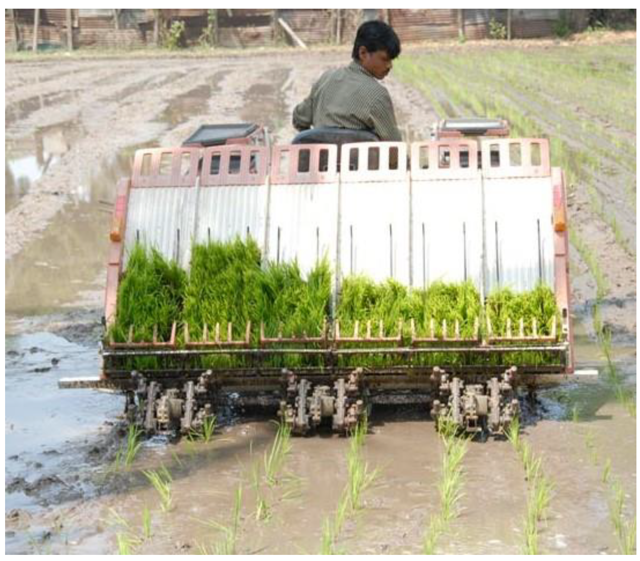
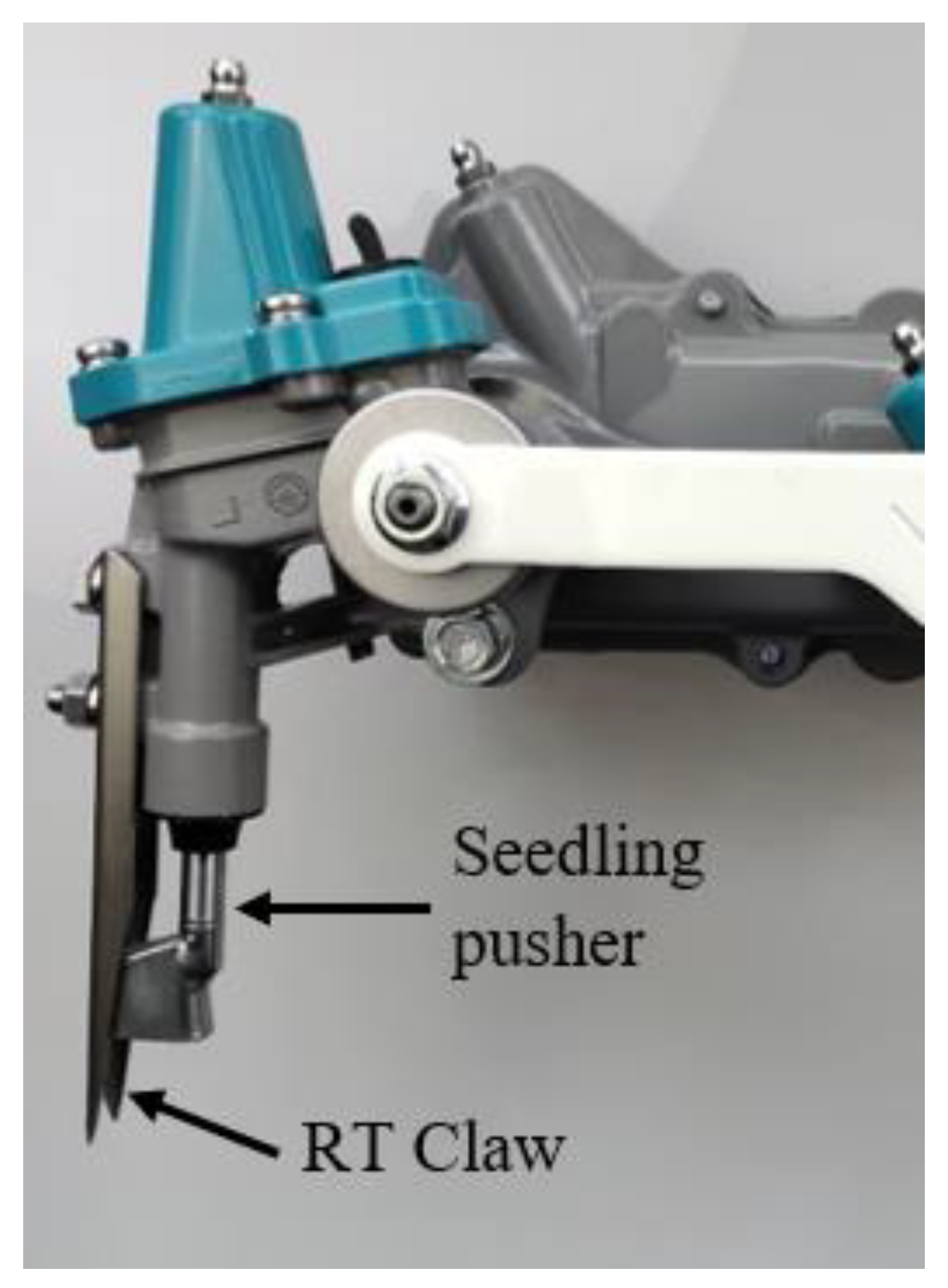
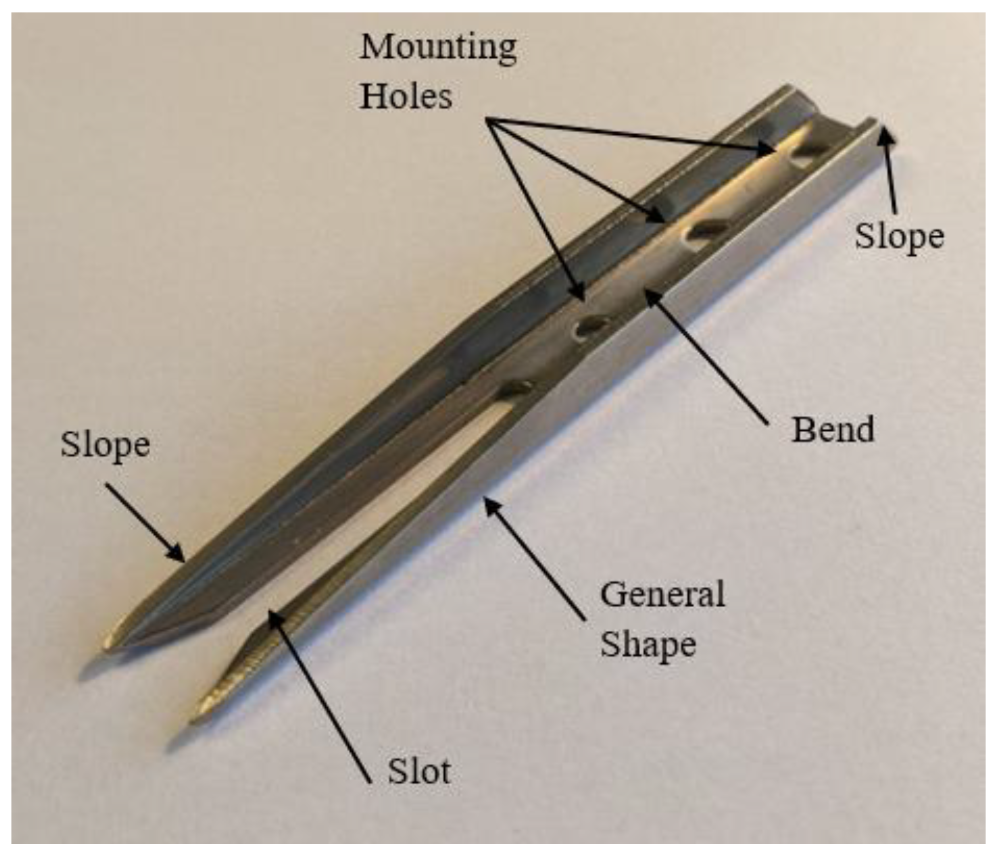
1.2. Rice Transplanting

Rice seedlings are grown in dense mats [13]. A seedling mat resembles grass sod with a root structure and a thin layer of soil. After growing to the desired height, a seedling mat is cut into smaller sections and placed onto the rear of a rice transplanter (Figure 1). The rice transplanter’s planting arm, located at the bottom rear of the machine, rotates and plants individual rice seedlings into a rice paddy, as seen in the bottom of Figure 1. The planting arm (Figure 2) consists of two rotating planting claws/forks that pluck individual rice seedlings from a seedling mat and then plant the rice seedlings into the ground. Current rice transplanters have a seedling pusher that sits inside the rice transplanter claw and pushes out rice seedlings when the claw contacts the rice paddy. Figure 2 shows a Kubota rice transplanter’s planting arm assembly with the seedling pusher and rice transplanter claw labeled. The rice transplanter claw is identified as a critical spare part due to its propensity to wear and its need for replacement under normal operation. The wear of a rice transplanter claw is due to repeated dynamic contact with seedling nursey mats, rice paddies, and field debris. Figure 3 shows a rice transplanter claw with basic dimensions.

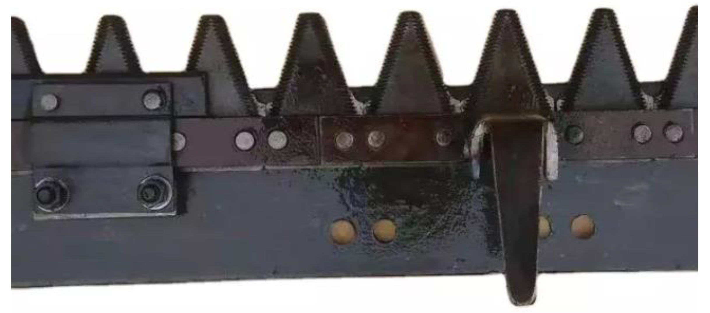
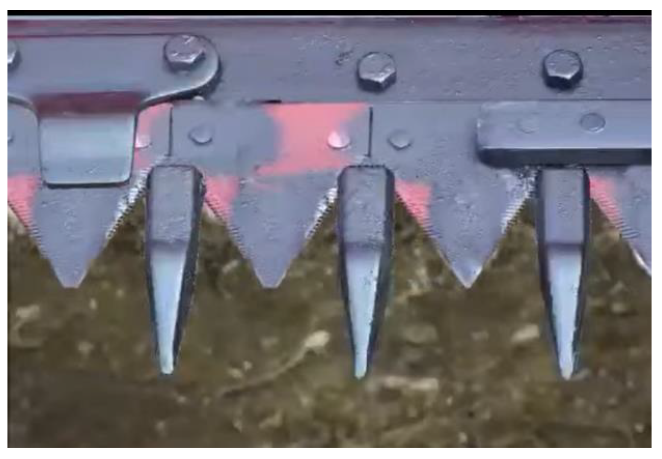
1.3. Combine Harvester

Combine harvesters reap, thresh, and winnow grains in a single continuous process. Their use greatly reduces the labor required to harvest both rice and wheat when compared to traditional manual processes, as well as the mechanization of individual harvesting processes (reaping, threshing, and winnowing). The traditional and individual mechanized harvesting methods require approximately 28 and 15 times more labor, respectively, when compared to the use of combine harvesters [16]. This reduction provides a farmer protection from the shrinking agricultural labor market and rising labor wages, while reducing the drudgery and time required for manual harvesting.
The first step in the grain harvesting process is to reap or cut the stalks of mature rice or wheat plants so that they can either be processed manually, through mechanized threshing and winnowing, or processed immediately within a combine harvester. Currently, there are two types of combine harvesters that use cutter bar blades in Bangladesh: full-feed combine harvesters and half-feed combine harvesters. Reaping is accomplished by reciprocating cutter bars with blades that are attached along the bottom front edge of the combine harvesters. Figure 4 shows a cutter bar of a half-feed combine harvester, which consists of top and bottom sets of blades. The cutting and shearing forces between the top and bottom sets of blades cut crop stalks. The cutter bar binder bolts into the lower cutter bar base and establishes the clearance between the top and bottom blades through a combination of spacers and shims. Figure 5 shows a cutter bar of a full-feed combine harvester, which consists of one set of blades attached to a cutter bar base using press pins. The cutter bar base is attached to a reciprocating arm, which creates a horizontal linear motion of the blades. The cutter bar base and blades move within a set of combine harvester tines, which act to hold crop stalks so that shearing and cutting forces can be applied by the reciprocating blades. Combine harvester blades were selected for study because of their propensity to wear and their need for replacement due to contact with crop stalks and field debris. Figure 6 and Figure 7 show full-feed and half-feed combine harvester blades with basic dimensions.

2. Materials and Methods

The development of the rice transplanter claw and combine harvester blade manufacturing processes is tailored to the worker skills and machine tools that are available in small machine shops in Bangladesh. The characterization of the original spare parts is presented first. Then, the most appropriate manufacturing processes to produce rice transplanter claws and combine harvester blades are selected. Next, the modeling, simulation, and experimentation used in the development of the blanking, bending, and forging die sets used in the fabrication of the rice transplanter claws and combine harvester blades are presented. Finally, the results of the characterization, experimental testing, and finite element method (FEM) simulations and their validation are presented.

2.1. Material Characterization

The material properties and the original manufacturing processes of the two parts are determined to allow for material recommendations to spare part manufacturers in Bangladesh. The background information on the manufacturing of these spare parts in South Asia was obtained from the YouTube videos described above. The equipment and the process flow diagrams for the low-, medium-, and high-capital-cost production processes that are used in this paper are, thus, identified and will be further described in Section 3. The hardness and X-ray fluorescence spectroscopy tests identify the strength and composition of the metals that are used to produce the original parts. The knowledge of the hardness of the original spare parts allows the establishment of quality control testing metrics to produce high-quality spare parts. These results can also be used to determine if the stock materials available in Bangladesh are suitable for the manufacturing of these two parts or if additional materials must be imported.
An X-ray fluorescence (XRF) spectroscopy is used to determine the elemental composition of the two spare parts. Unfortunately, an XRF cannot identify elements with atomic numbers less than 11. Therefore, the specific carbon content of the materials cannot be identified, and the percentage of carbon is estimated, which makes it harder to determine the specific alloys.
The testing for material hardness is repeatable in Bangladesh as many small machine shops own hardness testers for quality control. However, due to high import taxes and duties on imported steels, the stock materials available to agricultural workshops in Bangladesh come from dismantled decommissioned ships, which are cut into pieces in various shipyards in the Chittagong region of Bangladesh. Therefore, the specific elemental composition of the metals used by domestic manufacturers is not known to any degree of certainty and is not relevant to their day-to-day operations. In addition, the determination of elemental composition analysis using advanced techniques, such as XRF spectroscopy, is prohibitively expensive for small- and medium-sized agricultural workshops in Bangladesh. Therefore, hardness testing provides the best technique to characterize irons and steels used by Bangladesh manufacturers.
Three repetitions of the Rockwell hardness test are performed for each part, and the average is used as the final hardness value. The hardness values of the original rice transplanter claw and the half-feed combine harvester blades provide the reference values so that appropriate stock materials can be purchased.

2.2. Manufacturing Methods

The manufacturing methods used by the original manufacturers are identified by analyzing the claws and the blades. Figure 8 shows the original claw with the following features identified: general shape, bend, slot, mounting holes, and the slope toward the front of the claw. The general shape of the claw is defined as the shape of the blank before the operations that create the bend, slot, mounting holes, and slope.
After the initial assessments of the original rice transplanter claw and the combine harvester blades are completed, a morphological chart of the possible manufacturing methods for each product feature is created. Then, three manufacturing processes are created for each feature for different levels of initial capital cost. Table 1 and Table 2 show the three manufacturing processes listed by the initial capital cost of the equipment needed to produce rice transplanter claws and combine harvester blades. Comparative analyses between the various manufacturing processes are beyond the scope of this paper but can be found in reference [11].

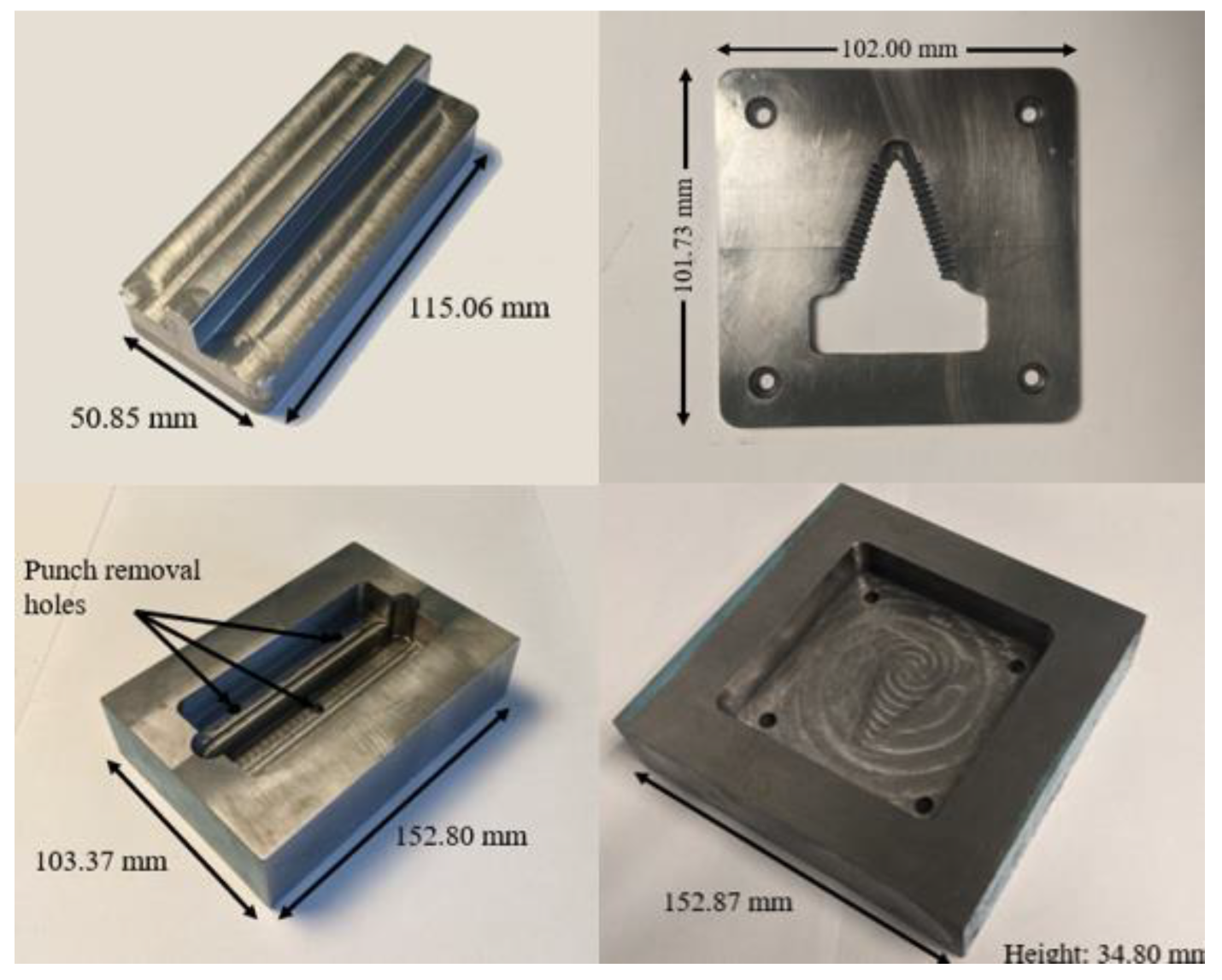
2.3. Design of Required Tooling

After determining the manufacturing methods for locally producing rice transplanter claw and combine harvester blades, the designs of the required tooling (punch/die sets) are completed for each manufacturing process. The designs of the punch/die sets for both rice transplanter claw and combine harvester blade manufacturing are divided into five steps: design of the original spare parts, preliminary design of the punch/die sets, testing of the preliminary design, finite element analysis of the punch/die sets, and final design.
The first step in the development of the bending-and-forging die sets is to develop models for the rice transplanter claw and the half-feed and full-feed combine harvester blades. The measurements of the original spare parts are taken with a digital caliper with an accuracy of ± 0.02 mm. These measurements are used to develop SolidWorks CAD models of the original parts.
After the modeling of the original spare parts, the initial designs of the rice transplanter claw bending punch/die set and the half-feed small bottom blade forging punch/die set are completed and subsequently machined out of A2 tool steel for experimental testing. Figure 9 shows the experimental bending-and-forging punch/die sets. The experimental punch/die sets are designed with a die pocket that centers the punch in the horizontal and vertical directions without the necessity to mount the punch and die to a standard die set. This is necessary due to the limited vertical space of the hydraulic press used for testing.
The experimental testing of the bending-and-forging punch/die sets is conducted to evaluate their performance at replicating the various parameters of the original spare parts and to determine the accuracy of the finite element analysis simulations. All tests are conducted at room temperature, at approximately 20 °C. Molybdenum disulfide is the lubricant for all tests. The rice transplanter claw and combine harvester blanks are fabricated using an OMAX Maxiem 1515 water jet. The rice transplanter blanks have a thickness of 1.9 mm and are made from 304 stainless steel, which is commonly found in Bangladeshi scrap metal markets [17]. The rice transplanter bending punch/die set is tested at maximum press forces of 22.7 metric tons and 45.4 metric tons. The combine harvester blade blanks have a thickness of 4.1 mm and are fabricated from 6061-T6 aluminum. This alloy is chosen to represent the properties of steel at hot forging temperatures, because hot forging was not available during laboratory testing. All tests of the forging punch/die set are conducted at a maximum force of 45.4 metric tons.

2.4. Numerical Simulations

The numerical simulations are conducted using DEFORM 3D (Version 11.1 published by Scientific Forming Technologies Corporation). DEFORM 3D is a process simulation system, which uses the finite element method to simulate manufacturing processes. In this study, DEFORM 3D is used to simulate both bending and forging operations to study the effects of changes to various design parameters made prior to and after the machining and testing of the physical prototypes. The settings used during the simulation of the operations with DEFORM 3D are constant for all simulations in this study. The preprocessor used is 3D Forming Express. 3D Forming Express sets many of the constraints to allow for ease of use when conducting studies on cold or hot forming operations. An example of a constraint set by the preprocessor is the constraint of the punch and die as rigid bodies. This sets the punch and die as “unable to be deformed,” which reduces the computing power needed as the internal compressive forces experienced by the punch and die are not calculated. The die is set as the fixed surface, with the punch moving into contact with the harvester blade material.
The process type is set to cold forming, which sets the temperature of the operation at 20 °C. The mesh is generated with the suggested system settings, which results in 86,862 elements and 20,198 nodes in the simulation of the bending operation of the machined bending punch and die set. The material of the workpiece is set to stainless steel 304 from the DEFORM material library. No material properties are set for the punch and die as they are considered rigid in the forming analysis. The movement type of the top die is set as hydraulic because potential manufacturers of rice transplanter claws tend to use hydraulic presses for the blanking and bending operations. Finally, the control settings are established. No changes are made to the settings under contact. The primary die stroke is set to a rough estimate of the total die stroke expected, and the exact amount box is left unchecked. In the stopping control tab, the maximum load is set to 50 metric tons for the simulation of the prototype bending punch and die set and 150 metric tons for the simulation of the final design.
Numerical simulations of the experimental testing are conducted and analyzed to determine and validate the accuracy of the DEFORM 3D tests. The details on the simulation conditions can be found in reference [11]. After the validation of the DEFORM 3D experimental testing model, numerical simulations are performed to analyze the effects of various punch/die design parameters, such as width, depth, and radius of the rice transplanter bending die, on the spare part geometry. Finally, numerical simulations are conducted on the final bending-and-forging punch/die set to determine the accuracy of the fabricated parts as well as the press forces required to complete the operations.

3. Results

3.1. Spare Part Market Analysis

Table 3 presents the market size analyses and current dealers’ sales prices for both the spare rice transplanter claws and the combine harvester blades within Bangladesh. Current dealers’ sales prices for combine harvester blades are obtained by CSISA-MEA staff through meetings with The Metal (Pvt.) Ltd., a major agricultural machinery and spare part importer in Bangladesh. Current dealers’ sales price for rice transplanter claws are obtained by CSISA-MEA staff through meetings with the Janata Engineering, a direct seller of rice transplanter claws. The current number of rice transplanter claws and combine harvester blades are determined by multiplying the number of transplanters/harvesters in Bangladesh by the number of claws/blades per machine. The market size is then determined by multiplying the current number of rice transplanter claws/combine harvester blades by the estimated number of replacements per year. Further details can be found in reference [11].

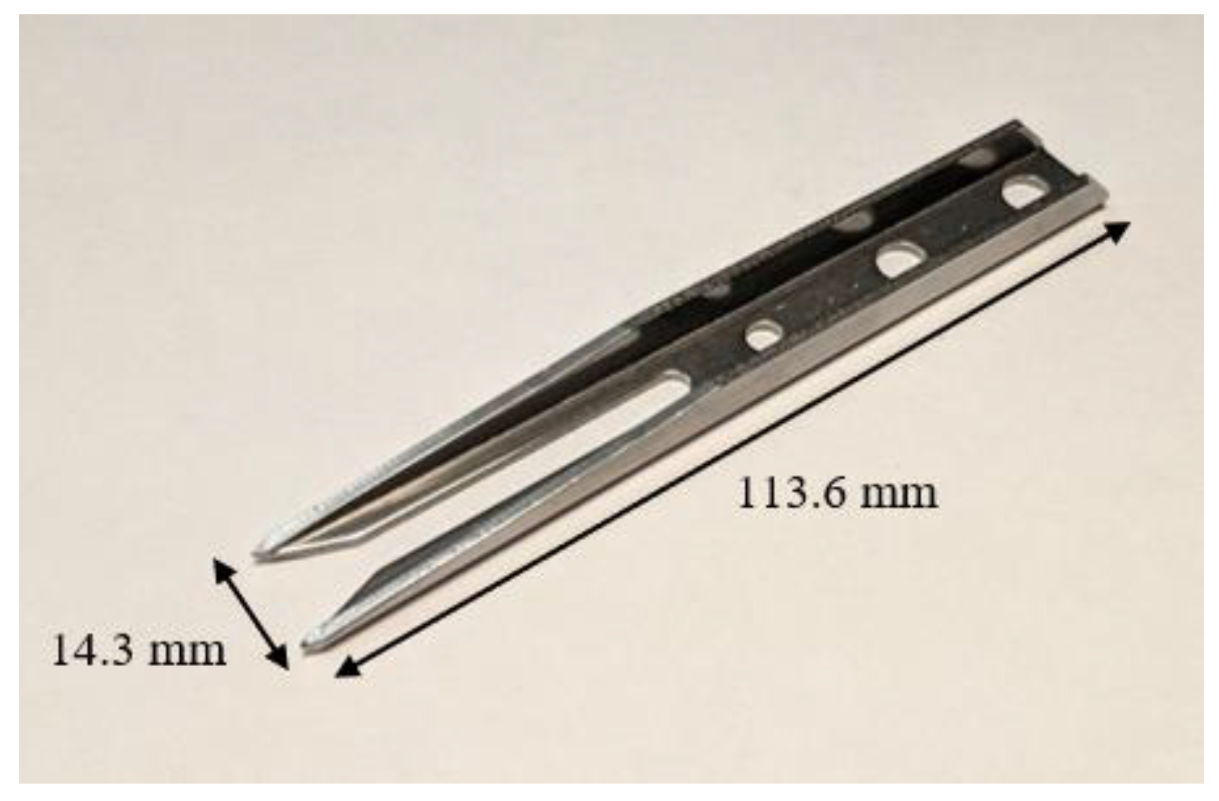
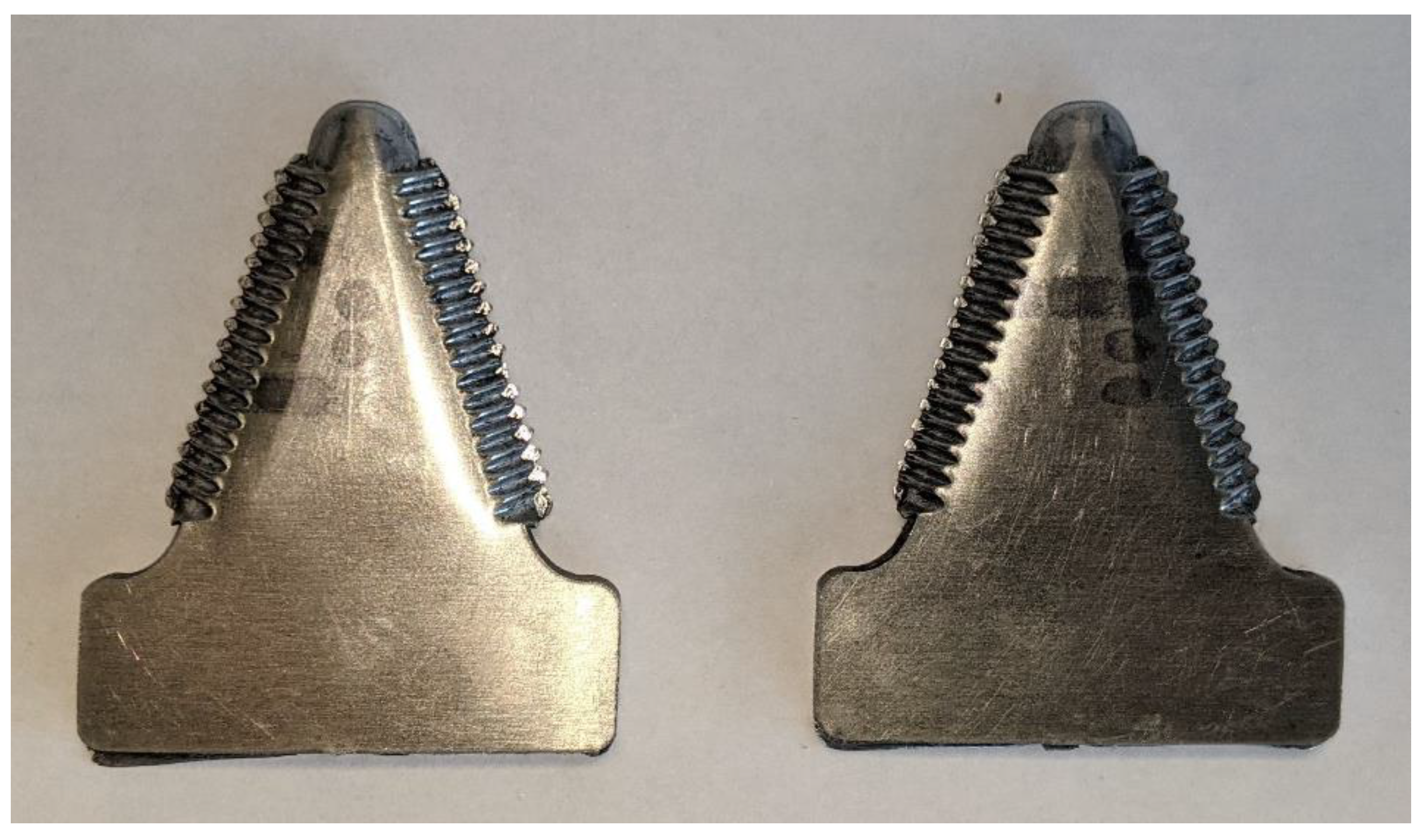
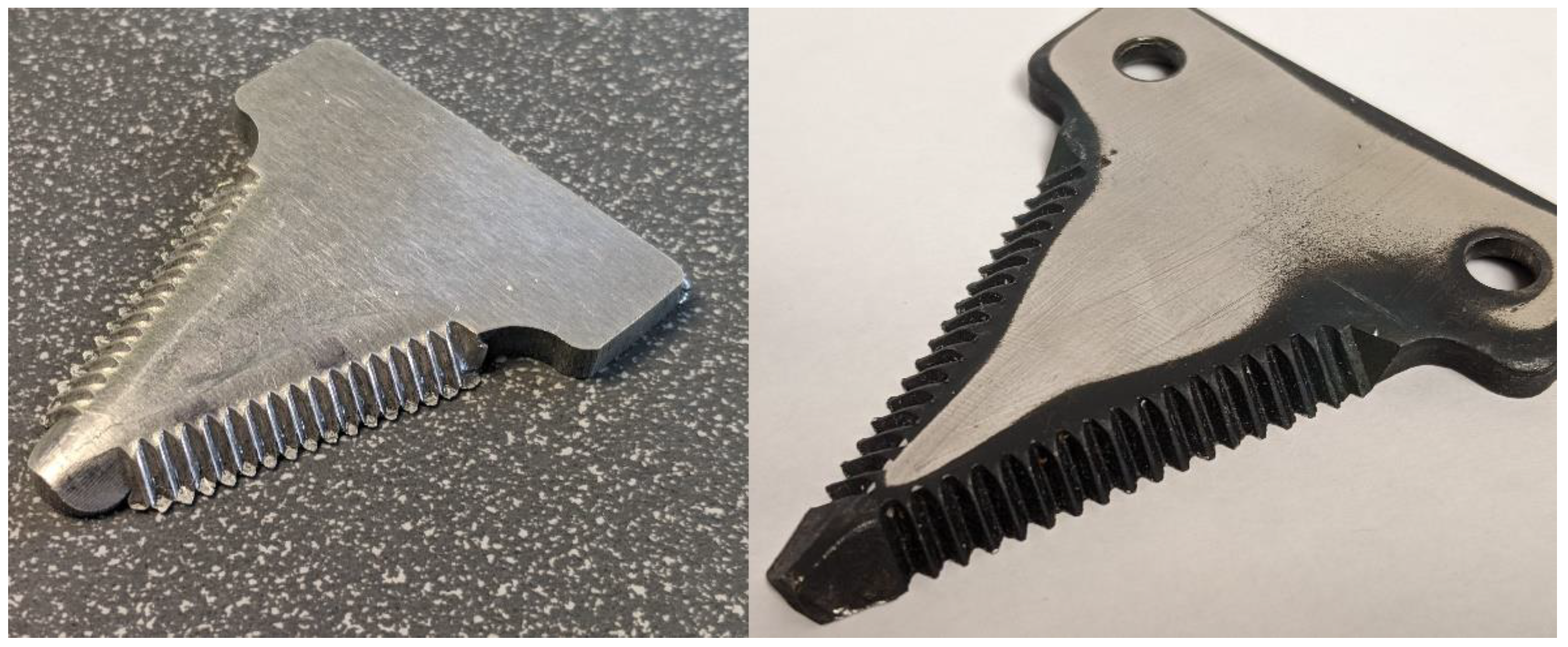
3.2. Rice Transplanter Claws

3.2.1. Initial Experimental Testing

The testing of the rice transplanter claw’s bending punch and die set is performed with press forces of 22.7 metric tons and 45.4 metric tons. To further quantify the performance of the prototype bending punch and die set, width measurements are taken at both ends of the blanks and at the center with both press forces of 22.7 metric tons and 45.4 metric tons. Table 4 presents these width measurements compared to the width measurements of the original rice transplanter claws.
The results of these initial tests presented in Table 4 demonstrate that the prototype bending punch and die set fails to create a bend that adequately replicates the parameters of the original rice transplanter bend with press forces of 22.7 metric tons and 45.4 metric tons. A comparison of the blanks’ width dimensions under the press forces of 22.7 metric tons and 45.4 metric tons reveals a difference in width; however, the difference is minimal when compared to the difference in width in the original rice transplanter claw. Therefore, it can be surmised that the difference in width between the test blanks and the original rice transplanter claw is not the result of a lack of press force but rather is due to the dimensions of the prototype bending punch and die set.

3.2.2. Numerical Simulation Validation

The validation of the rice transplanter claw bending DEFORM model is performed by comparing the results of the experimental tests to the results of the DEFORM model of the experimental testing computed in the 3D Forming Express preprocessor. Various width measurements along the blanks are taken in DEFORM and compared to the results of the prototype testing to validate the accuracy of the model. The width measurements are taken at the center and at both ends of the blanks after the bending operations are completed. The width values in Table 5 are the average of the measurements taken from four blanks after the bending operations at both 22.7 metric tons and 45.4 metric tons. The width measurements are taken with a digital caliper with an accuracy of ± 0.02 mm. The same width measurements are taken in the DEFORM model and are compared in Table 5. Equation (1) is used to determine the percent differences shown in Table 5.
Equation   1 : W D E F O R M W A V G W D E F O R M + W A V G 2 x   100 %
The results in Table 5 show that the DEFORM model of the testing punch and die set results in small variations from that of the experimental testing. An average width difference of 0.16   mm and 0.05   mm   is found between the DEFORM model and the experimental testing at the press forces of 22.7 metric tons and 45.4 metric tons, respectively. During the machining of the bending punch and die, a machining tolerance of ± 0.005   inches   or ± 0.125   mm is used. As the error between the DEFORM simulations and the experimental testing is smaller than the potential stack up of the machining tolerances, the error is considered negligible.

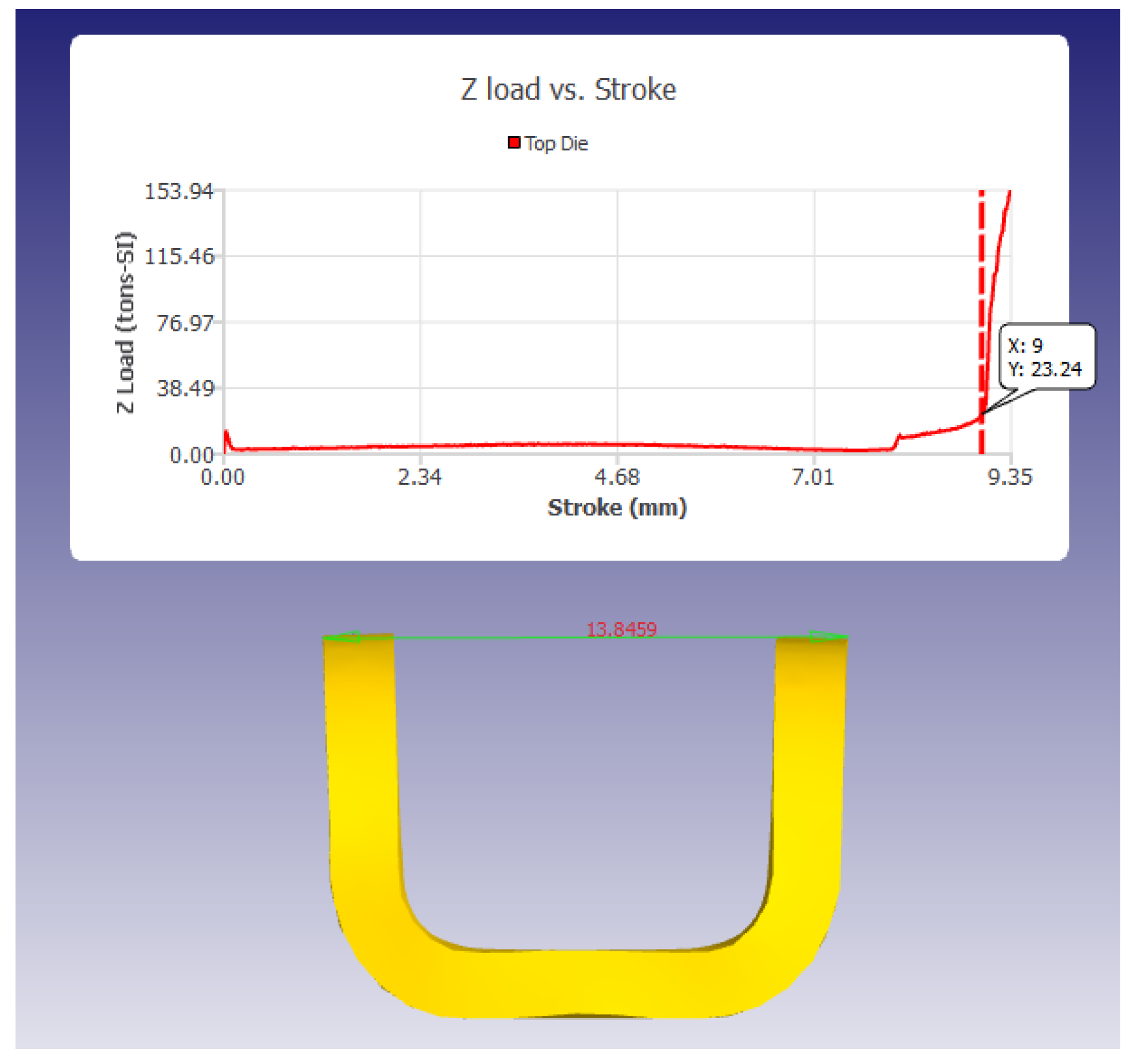
3.2.3. Numerical Simulation Results

Due to the inability to bend the blank to the proper angle, changes are made to the design of the bending punch and die set to rectify these errors. The radius of the valley in the die block is increased from 1.5 mm to 3.0 mm after the DEFORM model reveals that the blank does not contact the valley corner at the bottom of the punch stroke. To quantify the effects of these changes on the ability of the bending punch/die set to replicate the width of the original rice transplanter claw, numerical simulations of the updated bending punch/die set are conducted. Figure 10 shows the numerical simulation of the updated bending punch/die.
Table 6 displays the width measurements computed during the DEFORM simulation of the prototype testing and the final design simulation. These measurements highlight the improvements in performance gained through the increase in the die block valley radius from 1.5 mm to 3.0 mm. The width measurements in Table 6 account for the spring-back of the material due to the unloading of the punch. Spring-back is calculated using a sheet metal forming analysis that accounts for linear material strain hardening [18]. The average width difference between the updated DEFORM simulation + spring-back and the original rice transplanter claw is found to be 0.05 mm. Therefore, the design of the rice transplanter claw bending punch and die set is considered satisfactory. The tolerances of the bending punch and die set are set such that any variation in machining results in a larger rice transplanter claw width because an increase in width allows for more clearance for the mounting block and the seedling pusher. The rice transplanter claw fits around the mounting block and is secured by two nuts and bolts going through the mounting holes. The seedling pusher is also seated within the bend of the rice transplanter claw. Therefore, the width of the rice transplanter claw is important so that it can be properly mounted to the rice transplanter arm assembly.

3.2.4. Bending Sensitivity Analysis

A sensitivity analysis is performed on the DEFORM model of the bending punch and die set to determine the effects of different grades of stainless steel on the force required for the bending punch to reach an adequate die stroke. The steel grades tested are AISI 304 and AISI 316, as these are the available grades of stainless steel in Bangladesh [14]. The material properties are set through the DEFORM-3D material library. As the grade of stock materials is often not known in Bangladesh, the ability of a bending punch and die set to reach an adequate die stroke with a variety of stock materials is important for the functionality of the rice transplanter claw bending process in Bangladesh.
In a previous comparison of the prototype, the final DEFORM simulation, and the original rice transplanter claw, a die stroke of 9 mm was found to be adequate at closely reproducing the width of the original rice transplanter claw. Table 7 displays the force required to reach a die stroke of 9 mm for the four stock materials [19,20]. From Table 7, the force required to complete the bending operation of the rice transplanter claw manufacturing process is expected to be between 22.3 and 23.2 metric tons. Hydraulic and mechanical presses with maximum forces exceeding 50 metric tons are available in small machines throughout Bangladesh; therefore, the creation of a production line for rice transplanter claws would not require a high level of initial capital investment. If a press brake is used for the bending of the rice transplanter claw, the forces required for the tested stock materials, AISI 304 and AISI 316, are 1.05 and 1.03 metric tons, respectively. Therefore, it is recommended that a press brake with a maximum force of at least two metric tons be used in the manufacturing of rice transplanter claws.
The decision to complete the bending operation of the rice transplanter claw manufacturing process by using a mechanical of hydraulic press or a press brake is primarily determined by the cost of the machinery. If a spare part manufacturer does not own a mechanical or hydraulic press or a press brake, it is recommended that a mechanical or hydraulic press with a force of at least 50 metric tons be purchased to complete the bending operation because mechanical or hydraulic presses are found to be less expensive than press brakes during the review of online marketplaces. However, if a spare part manufacturer owns either a mechanical or hydraulic press or a press brake with an adequate maximum press force, it is recommended that the existing machinery be used to complete the bending operation. Hydraulic presses with maximum press forces of 100 metric tons or more are currently operational in machine shops in Bangladesh; therefore, the manufacturing process outlined in this paper may be implemented to fabricate rice transplanter claws within Bangladesh.

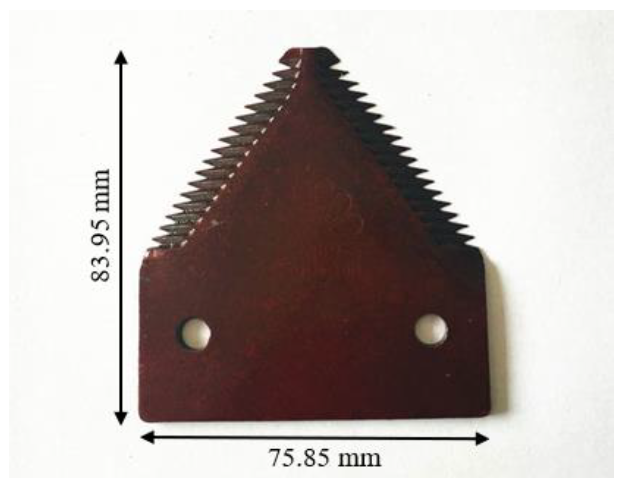
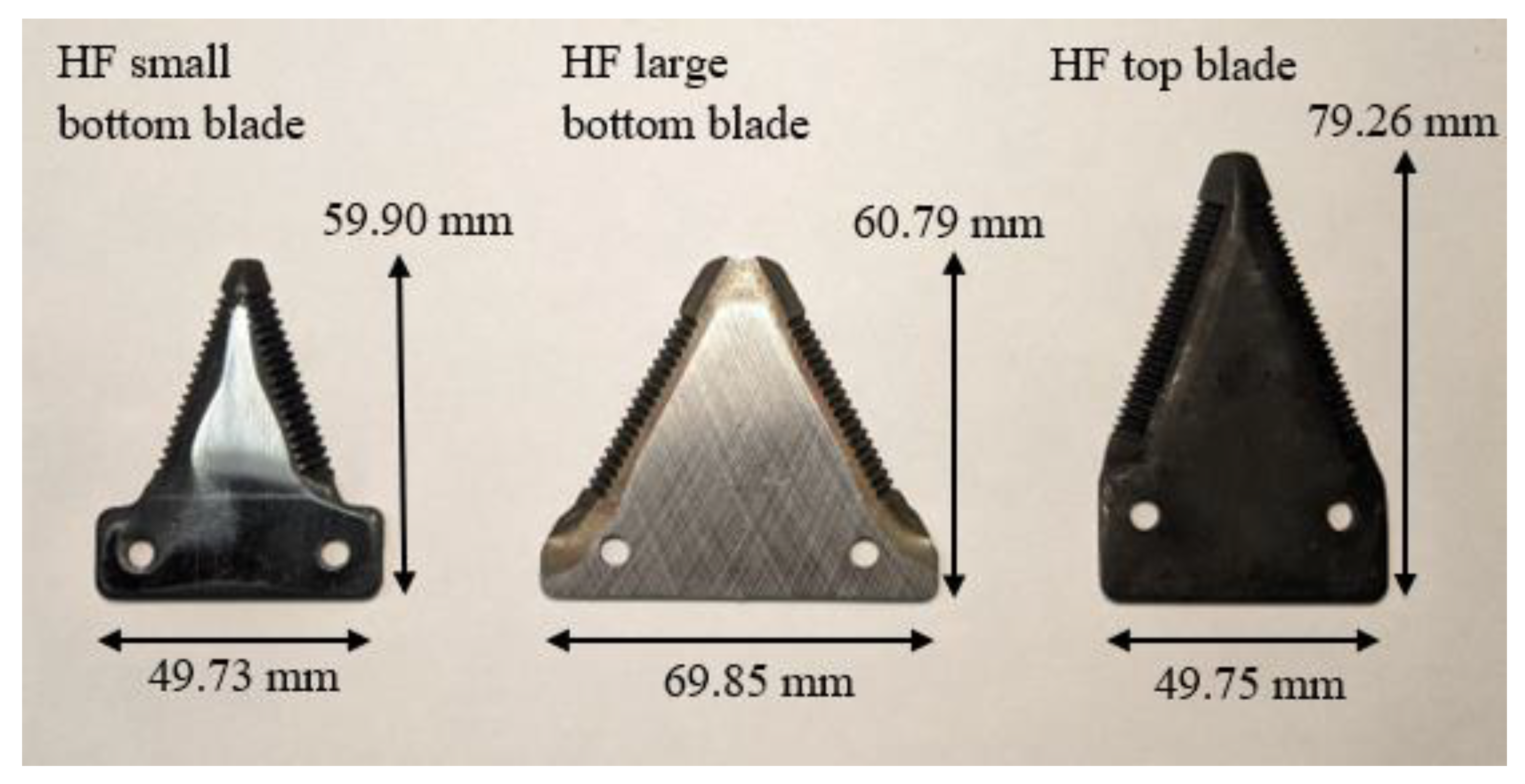
3.3. Combine Harvester Blades

3.3.1. Experimental Testing

The testing of the forging punch and die set is performed with a maximum press force of 45.4 metric tons. Figure 11 shows examples of the blanks after the experimental testing. Flash, which is excess material, can be seen around the bottom edge of the serrated edge as well as along the rear edge of the blade.
The average thickness of the flash around the edge of the test blanks is 0.54 mm. The thickness of the aluminum 6061-T6 used is 4.10 mm; therefore, the average total die stroke during testing is 3.56 mm. The thickness of the original half-feed small bottom blade is 3.70 mm; therefore, an additional press force is needed to achieve a die stroke equal to that of the original half-feed combine harvester small bottom blade as the punch does not bottom out in the die. As the testing blanks are fabricated from aluminum 6061-T6 and the press used has a maximum force of 45.4 metric tons, a direct comparison of the resulting dimensions of the experimental blades and the original half-feed combine harvester small bottom blade cannot be made. However, testing is conducted to test the viability of creating a serrated edge using forging, as well as validation of the forging DEFORM simulations. Figure 12 shows a closeup shot of the serrated edge of the test blade and the original half-feed blade. One can see that both blades have good definitions of the serrations and that the test blade is similar in appearance to the original blade. The test blade contains flash on the bottom edge because it has not been ground like the original blade; this will need to be removed. Similarly, the top of the test blade is somewhat rounded in the region of the serrations due to the forming operation; this will also need to be ground, similarly to the original blade.

3.3.2. Numerical Simulation Validation

The average thickness of the flash around the edge of the test blanks is 0.54 mm. The thickness of the aluminum 6061-T6 used is 4.10 mm; therefore, the average total die stroke during testing is 3.56 mm. The total die stroke of the DEFORM 3D Forming Express model is 3.45 mm at a force of 45.4 metric tons. Therefore, the difference between the die strokes is 0.11 mm, which corresponds to a percent difference of 2.3% between the experimental testing and the DEFORM simulation. During the machining of the bending punch and die, the standard machining tolerance of ± 0.005   inches   or ± 0.125   mm is used. As the error between the DEFORM simulations and the experimental testing is smaller than the standard machining tolerances, the error is considered acceptable.

3.3.3. Numerical Simulation Results

Numerical simulations are conducted to determine the effects of the addition of a flash gutter into the punch plate design. Conducting simulations using DEFORM also allows the testing of the full-feed combine harvester blade and two other half-feed combine harvester blades without having to machine the punch plates and conduct experimental testing. The material used for the numerical simulations of the full-feed and half-feed combine harvester forging punch/die sets is AISI 1070 due to its similarities to the original combine harvester blades. The AISI 1070 material properties are set through the DEFORM-3D material library. Figure 13 shows a graph of the force versus die stroke for the DEFORM simulations of the full-feed blade punch plate with and without the flash gutter. As seen in Figure 13, the performance of the full-feed punch plate is improved throughout the die stroke with the addition of the flash gutter because less force is required to obtain a specified die stroke. Numerical simulations comparing the forging punch/die sets with and without the flash gutter are performed on the full-feed and half-feed combine harvester blades. An increase in die stroke with the addition of the flash gutter is observed for all forging punch/die sets at the press forces of 100, 200, and 300 metric tons. Table 8 compares the original equipment manufacturer (OEM) blade thickness to the numerical simulation die stroke results of the punch/die set with the flash gutter at the press forces of 100, 200, and 300 metric tons.

3.3.4. Forging Sensitivity Analysis

A sensitivity analysis is completed on the DEFORM model of the forging punch and die set with the gutter to determine the effects of different grades of steel on the ability of the forging punch to reach an adequate die stroke. The steel grades tested are AISI 1008, AISI 1035, AISI 1043, AISI 1045, and AISI 1070. The material properties are set through the DEFORM-3D material library. As the elemental composition of stock materials is not known in Bangladesh, the ability of a forging punch and die set to reach an adequate die stroke with a variety of stock materials is important for the functionality of the serrated edge forging process in Bangladesh.
Table 9 displays the die strokes of the numerical simulation for full-feed combine harvester forging at the press forces of 50, 100, 200, and 300 metric tons for the five stock materials tested [21,22,23,24,25]. The largest measured range of the die strokes between the five stock materials is 0.75 mm, which occurs at a press force of 50 metric tons. As the press force increases, the range of the die strokes decreases to 0.12 mm, 0.04 mm, and 0.04 mm for the press forces of 100, 200, and 300 metric tons. As the ultimate tensile strength of the five stock materials ranges from 370 to 710 MPa, the full-feed forging punch and die set is not sensitive to deviations in the yield stress of the stock materials at press forces greater than or equal to 100 metric tons. The thickness of the original full-feed combine harvester blade is 1.80 mm; therefore, a die stroke equal to or greater than the original blade thickness is needed to forge the serrated edge. For the forging of the full-feed combine harvester blade’s serrated edge, a press force of 100–300 metric tons is recommended so that an adequate die stroke is reached or exceeded.
Table 10 displays the recommended press force for the forging operation of the full-feed and half-feed combine harvester blades. A press force of 100–300 metric tons is recommended for the forging of the serrated edge of the full-feed combine harvester blade. A press force of 200–300 metric tons is recommended for the half-feed top blade, while a press force of 300 metric tons is recommended for both the half-feed small bottom and large bottom blades.
Hydraulic presses with maximum press forces more than 100 metric tons are currently operational in machine shops in Bangladesh. No hydraulic presses with a maximum capacity of 300 metric tons are documented for the agricultural spare parts market in Bangladesh. The recommended stock material for full-feed combine harvester blades is AISI 1070. However, the results of the sensitivity analysis show that only minor deviations in die stroke are expected as a result of the variations in stock material tensile strengths in the range of 620–710 MPa.

3.3.5. Note on Field Testing

Field testing of both the rice transplanter claws and the combine harvester cutter blades is beyond the scope of this research due the limited ability to manufacture the quantities needed in the experimental facilities available. The purpose of the paper is to provide guidance for the manufacture of these parts, rather than to provide field testing. To assure valid field testing, the parts should be fabricated in Bangladesh using domestically obtained materials and then tested on farms in Bangladesh. These will be the next steps in this research.

4. Conclusions

This paper proposes the manufacturing processes and the tooling required for the fabrication of rice transplanter claws and combine harvester blades based on the machinery and economical constraints faced by small machine shops in Bangladesh. The proposed manufacturing methods allow for both the fabrication of rice transplanter claws and combine harvester blades with common machine tools and a hydraulic or mechanical press. These results and recommendations can be used by small machine shops in Bangladesh to expand their markets and, hence, their profits. Their production will serve the growing need for spare parts for rice transplanters and combine harvesters, which are needed to grow the crops required to meet the growing food demands of Bangladesh.

4.1. Rice Transplanter Claws

The results of the rice transplanter claw numerical simulations reveal that the bending punch/die sets achieve an average width difference of 0.05 mm between the original rice transplanter claws and those formed using the methods described in this paper. The results from the sensitivity analysis show that, for stainless steel 304 and 316, the force required to bend the rice transplanter claw is 22.3–23.2 metric tons. Therefore, a press with a maximum force of at least 50 metric tons is recommended for the bending of rice transplanter claws.

4.2. Combine Harvester Blades

The results of the numerical simulations for the forging of the combine harvester blades reveal that a press force of at least 100 metric tons is needed for the full-feed combine harvester blades and a press force of 300 metric tons is needed for the half-feed combine harvester blades. The results of the combine harvester forging die sensitivity analysis indicate that there is little deviation in the die stroke versus press force relationship for materials with tensile strengths between 620 and 710 MPa. Therefore, a press with a maximum force between 50 and 300 metric tons is recommended for the forging of combine harvester blades.

Author Contributions

Conceptualization, W.S. and J.C.; methodology, W.S. and J.C.; software, W.S.; validation, W.S.; formal analysis, W.S; investigation, W.S.; resources, W.S. and J.C..; data curation, W.S.; writing—original draft preparation, W.S.; writing—review and editing, J.C..; visualization, W.S.; supervision, J.C.; project administration, J.C.; funding acquisition, J.C. All authors have read and agreed to the published version of the manuscript.

Funding

This research was funded by the USAID’s Feed the Future Bangladesh Cereal Systems Initiative for South Asia—Mechanization and Extension Activity. The statements, data, views, and opinions of the authors expressed herein do not necessarily state or reflect those of the U.S. Government or the USAID.

Data Availability Statement

The data presented in this study are openly available in the thesis associated with this study, located at https://smartech.gatech.edu/handle/1853/67284 (accessed on 26 December 2022).

Conflicts of Interest

The authors declare no conflict of interest. The funders had no role in the design of the study; in the collection, analyses, or interpretation of data; in the writing of the manuscript; or in the decision to publish the results.

References

  1. United Nations Population Fund. World Population Dashboard-Bangladesh. 2022. Available online: https://www.unfpa.org/data/world-populations/BD (accessed on 13 June 2022).
  2. The World Bank. Population Density (People per sq. km of Land Area)–Bangladesh. 2020. Available online: https://data.worldbank.org/indicator/EN.POP.DNST?locations=BD (accessed on 13 June 2022).
  3. Bangladesh Rice Research Institute. Rice in Bangladesh. Bangladesh Rice Knowledge Bank. 2011. Available online: http://www.knowledgebank-brri.org/riceinban.php (accessed on 13 June 2022).
  4. Daily Sun. Bangladesh Ranks Third in Rice Production for Four Consecutive Years. 12 June 2022. Available online: https://www.daily-sun.com/post/625938/Bangladesh-ranks-third-in-rice-production-for-four-consecutive-years (accessed on 13 June 2022).
  5. Fuad, M.A.F.; Flora, U.M.A. Farm mechanization in Bangladesh: A Review. Int. J. Res. Bus. Stud. Manag. 2019, 6, 15–29. [Google Scholar]
  6. Alam, M.M. Trend of Agricultural Machinery and Spare Parts Manufacturing and Sales in Bangladesh. In Agricultural Mechanization in Bangladesh–The Future; CIMMYT: Dhaka, Bangladesh, 2022. [Google Scholar]
  7. Rahman, M.; Ali, R.; Oliver, M.H.; Hanif, A.; Uddin, Z.; Hasan, T.U.; Saha, K.K.; Islam, H.; Moniruzzaman, M. Farm mechanization in Bangladesh: A review of the status, roles, policy, and potentials. J. Agric. Food Res. 2021, 6, 100225. [Google Scholar] [CrossRef]
  8. Rahman, A.; Kabir, M.S.N.; Ali, M.R.; Rahman, M.M. Agricultural Mechanization in Bangladesh: Status and Challenges towards Achieving the Sustainable Development Goals (SDGs). Agric. Mech. Asia Afr. Lat. Am. 2020, 5, 106–120. [Google Scholar]
  9. Alam, M.M.; Khan, M.I.N.; Saha, C.K.; Rahman, A.; Bhuyian, M.G.K. Manufacturing of Agricultural Machinery in Bangladesh: Opportunities and Constraints; CIGR: Burnaby, Canada, 2017; Volume 19, pp. 122–135. [Google Scholar]
  10. Hossen, M.A. Mechanization in Bangladesh: Way of Modernization in Agriculture. Int. J. Eng. Trends Technol. 2019, 67, 69–77. [Google Scholar] [CrossRef]
  11. Schalch, W. Analysis of Manufacturing Methods and Die Design for Agricultural Parts in Bangladesh. Master’s Thesis, Georgia Institute of Technology, Atlanta, GA, USA, 2022. [Google Scholar]
  12. BESCO Harvester Blade Mould and Punch Press [Video]. Youtube. Available online: https://www.youtube.com/watch?v=Ok3Fag1fPs0&ab_channel=%E8%96%9B%E4%BA%AD (accessed on 19 November 2020).
  13. IRRI Rice Knowledge Bank. How to Prepare the Seedlings for Transplanting. 2014. Available online: http://www.knowledgebank.irri.org/step-by-step-production/growth/planting/how-to-prepare-the-seedlings-for-transplanting#modified-mat-nursery (accessed on 13 June 2022).
  14. Jashoda Agro Works. Exporters India. (n.d.). Available online: https://www.exportersindia.com/jashoda-agro-works/other-products.htm#1335441 (accessed on 26 December 2022).
  15. Kubota SPV6C Rice Transplanter Finger. Yancheng Foreign Machinery Parts Co., Ltd. (n.d.). Available online: https://www.alibaba.com/product-detail/KUBOTA-SPV6C-RICE-TRANSPLANTER-FINGER-PLANTING_62460998823.html?spm=a2700.details.0.0.4e985982AmrazR (accessed on 26 December 2022).
  16. Nath, B.; Paul, S.; Huda, M.; Hossen, M.; Bhuiyan, M.; Islam, A. Combine Harvester: Small Machine Solves Big Rice Harvesting Problem of Bangladesh. Agric. Sci. 2022, 13, 201–220. [Google Scholar] [CrossRef]
  17. Inspira. Raw Materials Market Assessment for Agro-Machines and Spare Parts; CIMMYT: Dhaka, Bangladesh, 2022; pp. 27–30. [Google Scholar]
  18. Kalpakjian, S.; Schmid, S.R. Bending of Sheet and Plate. In Manufacturing Processes for Engineering Materials, 5th ed.; Pearson Education Inc.: New York, NY, USA, 2008; pp. 360–371. [Google Scholar]
  19. Annealed 304 Stainless Steel. MakeItFrom.com. 30 May 2020. Available online: https://www.makeitfrom.com/material-properties/Annealed-304-Stainless-Steel (accessed on 10 June 2022).
  20. Annealed 316 Stainless Steel. MakeItFrom.com. 30 May 2020. Available online: https://www.makeitfrom.com/material-properties/Annealed-316-Stainless-Steel (accessed on 10 June 2022).
  21. Cold Drawn 1008 Carbon Steel. MakeItFrom.com. 30 May 2020. Available online: https://www.makeitfrom.com/material-properties/Cold-Drawn-1008-Carbon-Steel (accessed on 9 June 2022).
  22. Cold Drawn 1035 Carbon Steel. MakeItFrom.com. 30 May 2020. Available online: https://www.makeitfrom.com/material-properties/Cold-Drawn-1035-Carbon-Steel (accessed on 9 June 2022).
  23. Annealed and Cold Drawn 1043 Carbon Steel. MakeItFrom.com. 30 May 2020. Available online: https://www.makeitfrom.com/material-properties/Cold-Drawn-1043-Carbon-Steel (accessed on 10 June 2022).
  24. Annealed and Cold Drawn 1045 Carbon Steel. MakeItFrom.com. 30 May 2020. Available online: https://www.makeitfrom.com/material-properties/Annealed-and-Cold-Drawn-1045-Carbon-Steel (accessed on 10 June 2022).
  25. Annealed and Cold Drawn 1070 Carbon Steel. MakeItFrom.com. 30 May 2020. Available online: https://www.makeitfrom.com/material-properties/Annealed-and-Cold-Drawn-1070-Carbon-Steel/ (accessed on 9 June 2022).
Figure 1. Rice transplanter in a rice paddy field [14].
Machines 11 00219 g001
Figure 2. Kubota rice transplanter’s planting arm assembly [15].
Machines 11 00219 g002
Figure 3. Original rice transplanter claw [11].
Machines 11 00219 g003
Figure 4. Half-feed combine harvester cutter bar [11].
Machines 11 00219 g004
Figure 5. Full-feed combine harvester cutter bar [11].
Machines 11 00219 g005
Figure 6. Full-feed combine harvester blade [11].
Machines 11 00219 g006
Figure 7. Half-feed combine harvester blades [11].
Machines 11 00219 g007
Figure 8. Original rice transplanter claw with labeled features [11].
Machines 11 00219 g008
Figure 9. Machined bending-and-forging punches and dies. From top right (clockwise): bending punch, forging punch plate, forging die, and bending die [11].
Machines 11 00219 g009
Figure 10. Side view of the width measurement of the updated DEFORM rice transplanter claw simulation (not accounting for spring-back) [11].
Machines 11 00219 g010
Figure 11. Top view of two test half-feed combine harvester small bottom blades.
Machines 11 00219 g011
Figure 12. Comparison of the test blade (left) and the original half-feed combine harvester small bottom blade (right).
Machines 11 00219 g012
Figure 13. Force versus die stroke for the DEFORM forging simulation of the full-feed combine harvester blade.
Machines 11 00219 g013
Table 1. Rice transplanter claw manufacturing processes by initial capital cost.
Feature/
Manufacturing Process
LowMediumHigh
General Shape Machines 11 00219 i001
Shearing
Machines 11 00219 i002
Blanking
Machines 11 00219 i003
Blanking
Bend Machines 11 00219 i004
Bending Die/Press Brake
Machines 11 00219 i005
Bending Die/Press Brake
Machines 11 00219 i006
Bending Die/Press Brake
Mounting Holes Machines 11 00219 i007
Drilling
Machines 11 00219 i008
Drilling
Machines 11 00219 i009
Piercing
Slot Machines 11 00219 i010
Grinding
Machines 11 00219 i011
Grinding
Machines 11 00219 i012
Piercing
Slope Machines 11 00219 i013
Grinding
Machines 11 00219 i014
Grinding
Machines 11 00219 i015
Grinding
Table 2. Combine harvester claw manufacturing processes by initial capital cost.
Feature/
Manufacturing Process
LowMediumHigh
General Shape Machines 11 00219 i016
Bandsaw
Machines 11 00219 i017
Blanking
Machines 11 00219 i018
Blanking
Serrated Edge Machines 11 00219 i019
Forging
Machines 11 00219 i020
Forging
Machines 11 00219 i021
Forging
Mounting Holes Machines 11 00219 i022
Drilling
Machines 11 00219 i023
Drilling
Machines 11 00219 i024
Piercing
Parallel Sides Machines 11 00219 i025
Grinding
Machines 11 00219 i026
Surface Grinding
Machines 11 00219 i027
Surface Grinding
Table 3. Estimated spare parts’ market size.
Part Market   Size   p a r t s y r Current Market Price (USD)
Rice Transplanter Claw18,0962.15
Combine Harvester Blade135,900
Full-feed blade 1.08
Half-feed small bottom blade 1.51
Half-feed large bottom blade 3.76
Half-feed top blade 1.61
Table 4. Part width of the test blanks versus the original rice transplanter claw.
MeasurementOriginal (mm)22.7-Metric-Ton Test Blank (mm)45.4-Metric-Ton Test Blank (mm)
Left Side14.216.316.1
Center14.316.516.1
Right SideN/A16.516.0
Table 5. Part width of the test blanks versus DEFORM simulation of the prototype testing.
LocationDEFORM 22.7-Metric-Ton Simulation (mm)Experimental 22.7- Metric-Ton Test Blank (mm)22.7-Metric-Ton Percent DifferenceDEFORM 22.7-Metric-Ton Simulation (mm)Experimental 22.7-Metric-Ton Test Blank (mm)22.7-Metric-Ton Percent Difference
Left Side16.316.30.2516.116.10.19
Center16.316.51.1016.116.10.37
Right Side16.216.51.3516.116.00.31
Table 6. Comparison of the DEFORM simulation width measurements of the final bending punch and die set with spring-back due to unloading.
MeasurementDEFORM Final Design Simulation + Spring-Back (mm)Original Rice Transplanter Claw (mm)
Left Side14.214.2
Center14.214.3
Right Side14.1N/A
Table 7. Results of the sensitivity analysis of the rice transplanter claw bending punch and die set.
Stock Material σ U T S   ( MPa ) Bending Press Force (Metric Tons)Maximum Press Brake Force (Metric Tons)
AISI 30458023.241.05
AISI 31657022.231.03
Table 8. Comparison of the DEFORM forging simulation results to the original combine harvester blade thickness.
BladeOEM Blade Thickness (mm)Die Stroke
(100 Metric Tons) (mm)
Die Stroke
(200 Metric Tons) (mm)
Die Stroke
(300 Metric Tons) (mm)
Full-feed blade1.801.821.891.90
Half-feed small bottom blade3.693.263.523.71
Half-feed large bottom blade
Half-feed top blade
3.70
3.46
3.46
3.27
3.62
3.58
3.68
3.68
Table 9. Sensitivity analysis results for the full-feed forging punch and die set.
Die Stroke (mm)
Material σ U T S   ( MPa ) 50 Metric Tons100 Metric Tons200 Metric Tons300 Metric Tons
AISI 10083701.811.881.911.92
AISI 10356201.191.851.901.93
AISI 10437101.151.821.881.91
AISI 10456601.111.781.871.89
AISI 10706401.211.821.891.90
Table 10. Recommended press force for combine harvester blade forging operation.
Stock MaterialPress Force (Metric Tons)
Full-feed blade100–300
Half-feed small bottom blade300
Half-feed large bottom blade300
Half-feed top blade200–300
Disclaimer/Publisher’s Note: The statements, opinions and data contained in all publications are solely those of the individual author(s) and contributor(s) and not of MDPI and/or the editor(s). MDPI and/or the editor(s) disclaim responsibility for any injury to people or property resulting from any ideas, methods, instructions or products referred to in the content.

