Article

Investigation of Flow and Heat Transfer Characteristics in Microchannels with Fins

1
National Key Laboratory of Science and Technology on Aero-Engine Aero-Thermodynamics, Beihang University, Beijing 100191, China
2
Research Institute of Aero-Engine, Beihang University, Beijing 100191, China
*
Author to whom correspondence should be addressed.
Machines 2023, 11(2), 154; https://doi.org/10.3390/machines11020154
Submission received: 30 November 2022 / Revised: 28 December 2022 / Accepted: 9 January 2023 / Published: 22 January 2023
(This article belongs to the Special Issue Selected Papers from CITC2022)

Abstract

:
A highly efficient thermal management is imperative to overcome the main challenges associated with heat extraction requirements in electronics. In this study, the flow and heat transfer characteristics of microchannels with various types of fins were numerically analyzed for Re = 0–500 (Re: Reynolds number). Investigation of the aspect ratio, incident angle, and smoothness as well as the flow and heat transfer behaviors revealed the exceptional performance of the optimized fin structure, up to a performance evaluation criterion of 1.53. At large Re values, the fin with a high aspect ratio, small incidence angle, and high smoothness showed the best performance, as it avoids stagnation zones because of flares and sharp corners and simultaneously leads to boundary layer destruction and redevelopment. Interestingly, the microchannel without internal microstructures performed well at small Re values. Among all the designed variables, the influence of the incident angle was superior owing to its ability to generate significant vortices by periodically changing the channel cross-sectional area and flow direction. The conclusions can be innovatively generalized to other microchannels with fins.

1. Introduction

With the rapid development of micro-electromechanical systems (MEMS) and very large-scale integration (VLSI), excessive heat loads on devices have become a critical concern for the electronics industry. An excessive heat load can damage the components and reduce the precision of the apparatus or other normal working states, and approximately 55% of device failure is associated with a high operating temperature [1]. Therefore, an efficient cooling method is urgently required to solve the heat-loading issues.
Microchannels with liquid forced convective heat transfer are among the most promising and effective solutions [2,3]. They can simultaneously increase the specific surface area and reduce the cross-sectional area, thereby significantly improving the heat transfer efficiency with less working fluid. Because of their high efficiencies, compact structures, and easy integration with microchips, such microchannels are widely applied in machinery [4], chemicals [5], aerospace applications [6], solar energy-based applications [7,8,9], and microelectronics [10].
Since the pioneering work by Tuckerman et al. [11] in 1981, researchers have carried out extensive investigations on the flow and heat transfer characteristics of microchannels. Tao et al. [12] conducted a unified single-phase convective heat transfer analysis using the field synergy principle and summarized methods that can improve the thermal performance of such microchannels, including a decrease in the thermal boundary layer and an increase in flow interruptions. Over the years, various other studies on microchannels with arrays of fins that can disturb fluids have been conducted to further enhance the thermal performance of microchannels.
To date, several authors have made efforts to identify the most optimized fin shape to obtain the best performance. İzci et al. [13] simulated microchannels with circular, square, lozenge-shaped, rectangular, triangular, and airfoil-shaped fins. The corresponding results revealed that among all these shapes, rectangular fins have the largest Nusselt number (Nu), whereas conical fins exhibit the best heat transfer capacity. Abdoli et al. [14] investigated the heat transfer characteristics of staggered fins with different shapes, i.e., hydrofoil, modified hydrofoil, circular, and symmetrically convex. Their results showed that hydrofoil-shaped and convex fins reduce pressure by 30.4% and 47.3%, respectively.
Apart from the fin shape, the effect of the fin size and its optimization have remained at the forefront of microchannel-based research over the years. Guo et al. [15] designed a silicon-based needle fin with a special shape to investigate the effect of fin height and fin spacing on the friction coefficient, with Re ranging from 1 to 100. The results showed that the microchannel with rougher fins exhibited a smaller pressure drop and friction coefficient. Wang et al. [16] studied the characteristics of annular fin-and-tube heat exchangers with elliptical fins and analyzed the effects of the ellipse attack angle and diameter ratio on the thermal performance.
According to previous studies, the arrangement of the fins also play a deterministic role in regulating the thermal performance of microchannels. Limbasiya et al. [17] evaluated the effect of microchannel fins on forced air convection and noticed that microchannels with staggered fins showed better thermal performances than the symmetrical ones. Kang et al. [18] studied the microfluidics in silicon-based microchannels with different fin arrangements and spacings and Re ranging from 60 to 650. According to these authors, microchannels with cross-arranged fins show higher resistance and heat transfer efficiency, and increasing the density of the fins enhances the thermal performance. However, Jia et al. [19], who investigated microchannels with fins at different locations, revealed that the microchannels with uniform fin distributions exhibit the best thermal performance. In this fin configuration, the bottom wall temperature is the lowest and is well distributed. In addition, extensive studies have been conducted to analyze the effects of cavities [20,21,22], nanofluids [23,24,25,26,27], and other parameters/factors on the thermal performance of microchannels.
To date, the studies on microchannels have been primarily focused on geometry optimization of the fin structures, although they have been largely concentrated on simple comparisons of the effects of different fin structures. The findings of these previous studies do not shed light on the associated mechanisms, and they fail to provide conclusive data on optimized fin structures for different cases and applications.
This study was designed to investigate the flow and heat transfer characteristics of microchannels with fins. First, a series of fins with different aspect ratios, incident angles, and smoothness values were designed using the control variable method. Then, the thermal performance of the newly designed microchannel was evaluated and compared using the Poiseuille number (Po), Nu, and the performance evaluation criterion (PEC). Finally, the relevant mechanism was analyzed to deduce the parameter design principle and optimization direction, which can be used as references for designing innovative microstructures that can be used in high-efficiency cooling systems. The innovations of this work are as follows: (1) quantitative analysis of the effect of fin structure parameters on flow and heat transfer characteristics, (2) data summarization into conclusions that can be generalized to microchannels with other fin structures, and (3) determination of the mechanism underlying the observed effects of different fin structures on the flow and heat transfer characteristics of microchannels.

2. Methods

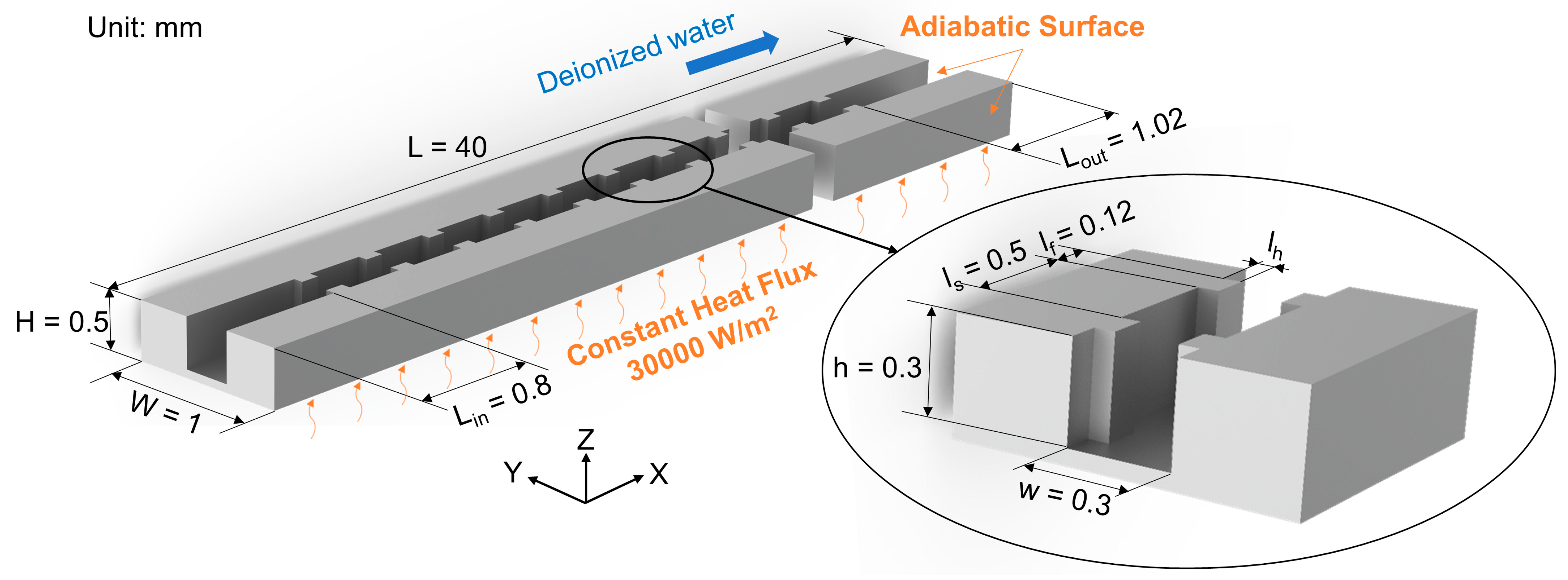
2.1. Physical Model and Simulation Assumptions

The physical model, shown in Figure 1, was designed according to the results obtained from different scientific research projects undertaken by the authors and the existing studies [20,21,22]. The length, width, and height of the microchannels were set to L = 40 mm, W = 1 mm, and H = 0.5 mm, respectively. The microchannel was divided into an inlet section of Lin = 0.8 mm, a middle section, and an outlet section of Lout = 1.08 mm along the flow direction. In the middle section, fins were created symmetrically on the sidewall. The fin width and spacing were lf = 0.12 mm and ls = 0.5 mm, respectively. The cross-section of the fluid domain was 0.3 × 0.3 mm. The top surface of the fluid domain was closed and did not allow any mass or heat transfer. A constant heat flux density of 30,000 W/m2 was applied to the bottom surface of the solid, and the other walls were thermally insulated. Silicon was selected as the channel solid, and deionized water was used as the fluid. The Re range was set to 0–500.
Based on previous studies, here, we analyzed the fin aspect ratio, fin incident angle, fin smoothness, and their effects on the flow and heat transfer characteristics. Although the structure of the fin is relatively simple, there are many variables, and thus, the control variable method was applied.
Figure 2 shows schematic illustrations of the microchannels and fins based on the established model and considered parameters, and the geometrical parameters of fins are presented in Table 1.
First, we investigated microchannels without internal microstructures as the control group. The aspect ratio of fins is defined as the ratio of the fin width to the fin height and is denoted as “m.” To analyze the effect of fin shape, the fins were marked as #2 (m = 3), #3 (m = 2), and #4 (m = 1.5) with a fixed fin width of 0.12 mm and different fin heights of 0.04, 0.06, and 0.08 mm, respectively. Next, the incident angle of the fins is defined as the angle between the mainstream direction, and the plane of the leading edge of the fins and is denoted as “α.” To investigate the effect of the fin’s leading edge, the fins were marked as #3 (α = 90°), #5 (α = 45°), and #6 (α = 26°). Similarly, the smoothness of fins, denoted as “n”, is defined as the number of edges of a single fin, and to evaluate the effect of the edges and corners, the fins were marked as #3 (n = 3), #7 (n = 5), and #8 (n = ∞).

2.2. Boundary Conditions and Data Processing

In this study, the range of Re was adopted as 0–500, and the hydraulic diameter (Dh) of the microchannel was set as 0.3 mm. Further, deionized water was used as the working fluid, and the mean free path (I) was set as 5.752 × 10⁻⁸ m at normal temperature and pressure [28].
According to Xu et al. [29], deionized water exhibits laminar flow in a silicon-based channel with Dh = 0.03–0.344 mm and Re < 1500; therefore, within the scope of this study, the flow state of the working fluid can be considered as laminar flow.
The continuous medium hypothesis holds if the Knudsen number is less than 0.001 [30]. The Knudsen number can be calculated using the following equation:
K n = I D h = 5.752 × 10 8 3 × 10 4 = 1.9173 × 10 4 < 0.001 .
For the calculation, the following assumptions can be made:
  • Laminar flow.
  • The flow satisfies the continuous medium hypothesis.
  • The flow is steady and incompressible.
  • The thermophysical properties of the solid are constant.
  • Body force and radiation heat transfer are ignored.
Judy et al. [31] experimentally investigated a rectangular microchannel with Re = 8–2300 and a hydraulic diameter >0.015 mm and found that the traditional theoretical models can be applied to determine the hydraulic and thermal characteristics of microchannels. Qu et al. [32] obtained the same results by using a Re of 139–1672 in their experiments.
Based on the aforementioned assumptions and experimental conclusions, the governing equations for the conservation of mass, momentum, and energy are as follows [28].
u i x i = 0 , i = 1 , 2 , 3 ,
x i ( ρ f u i u j ) = p x j + x i [ μ f ( u j x i + u i x j ) ] , i , j = 1 , 2 , 3 ,
x i ( ρ f u i C p f T ) = x i ( λ f T x i ) + μ f [ 2 ( u i x i ) 2 + ( u j x i + u i x j ) 2 ] , i , j = 1 , 2 , 3 ,
where ρ represents the density, u represents the fluid velocity, μ represents the fluid dynamic viscosity, p represents the pressure, T represents the temperature, Cp represents the specific heat, and subscript s and f represent solid (silicon) and fluid (deionized water), respectively.
The boundary conditions are as follows:
Boundary conditions at the inlet:
x = 0   u = u i n , T f i n = 300   K .
Boundary conditions at the outlet:
x = L , p o u t = 1   atm , T f o u t = 300   K .
A constant heat flux density of 30,000 W/m2 was applied to the bottom surface of the solid, and the following equations were obtained:
z = 0 , q w = λ s T s n = 30000   W / m 2 .
All the surfaces were adiabatic, except the solid–liquid contact and heating surfaces at the bottom of the solid. Thus, we obtain
q w = λ s T s n = 0 .
In the aforementioned equations, λ represents the thermal conductivity; the subscript in represents inlet; n represents the normal direction to the wall; u represents the velocity; the subscripts x, y, and z represent the velocity components along the x, y, and z axes, respectively; the subscript s represents solid (silicon); and the subscript f represents fluid (deionized water).
The thermophysical properties at room temperature and atmospheric pressure used in the calculations are presented in Table 2.
In the analysis, the flow and heat transfer characteristics are determined by Po and Nu, respectively. The comprehensive thermal performance is evaluated by the PEC, which considers both the flow and heat transfer. The calculation formulas are as follows [28,33]:
Re = ρ u D h μ ,
P o = f Re = 2 Δ p D h Re ρ l u 2 ,
N u = h D h λ ,
P E C = N u / N u 0 Po / P o 0 ,
where ρ represents the density of the fluid, u represents thethe flow resistance within the investigated range, although this increase is less than that in average flow rate, Dh represents the hydraulic diameter of the channel, μ represents the fluid dynamic viscosity of the fluid, f represents the friction factor, Δp represents the pressure difference, l represents the distance used to calculate the pressure difference, λ represents the thermal conductivity of the fluid, subscript 0 represents the values for the microchannels without internal microstructures, and h represents the convective heat transfer coefficient, which can be calculated using the following equation [28]:
h = q w W L A ( T w T f ) .
Here, A represents the solid–liquid contact area, W represents the channel width, L represents the channel length, Tw represents the qualitative wall temperature, and Tf represents the qualitative fluid temperature.
To improve the accuracy of the simulation, the pressure difference was evaluated only in the fully developed section to eliminate the adverse effects of the inlet section. The average wall temperature of the solid–liquid phase interface was considered as the qualitative wall temperature, and the weighted average temperature of the fluid at the inlet and outlet was adopted as the qualitative fluid temperature.

2.3. Grid Independence and Model Validation

In study, we adopted the ICEM software package and ANSYS FLUENT 19.0 for simulating the meshing and the calculations, respectively. Standard initialization was applied for the initialization, along with the second-order upwind scheme and SIMPLE algorithm for discretization and calculations, respectively. When the residual is less than 10−8, the result is considered to be convergent.
The primary aim was to confirm the grid independence. The number of grids ranged from 3.15 million to 58.47 million, increasing by 1.2 times, with a total of six sets. Nu and Po were used as the reference quantities to validate the mesh independence of the microchannels with semicircular fins and Re = 25. The deviations were calculated as follows:
e ( N u ) = | N u 2 N u 1 | N u 1 × 100 % ,
e ( P o ) = | P o 2 P o 1 | P o 1 × 100 % ,
where e represents the deviation, Nu1 and Po1 represent the reference values of the smallest grid No. 6, and Nu2 and Po2 represent the values of the other grids. The corresponding results are presented in Table 3.
The deviation values of grid No. 5 are both less than 0.2%, which can balance the amount and accuracy of the calculation. Thus, the meshes for the other models were prepared by considering the size of mesh No. 5.
The calculated results were compared with those of the references to ensure a high accuracy. The results of the microchannel with no inside structure inside are verified with the theoretical value of 56.9 derived by Zhang et al. [34]. As presented in Table 4, the deviation value of the Po calculated from the fully developed sections deviates by less than 0.26%, which indicates the reliability and high accuracy of this model.

3. Results and Discussion

In this section, we present and discuss the analysis results of the flow and heat transfer characteristics, along with the effects of the aspect ratio, incident angle, and smoothness.

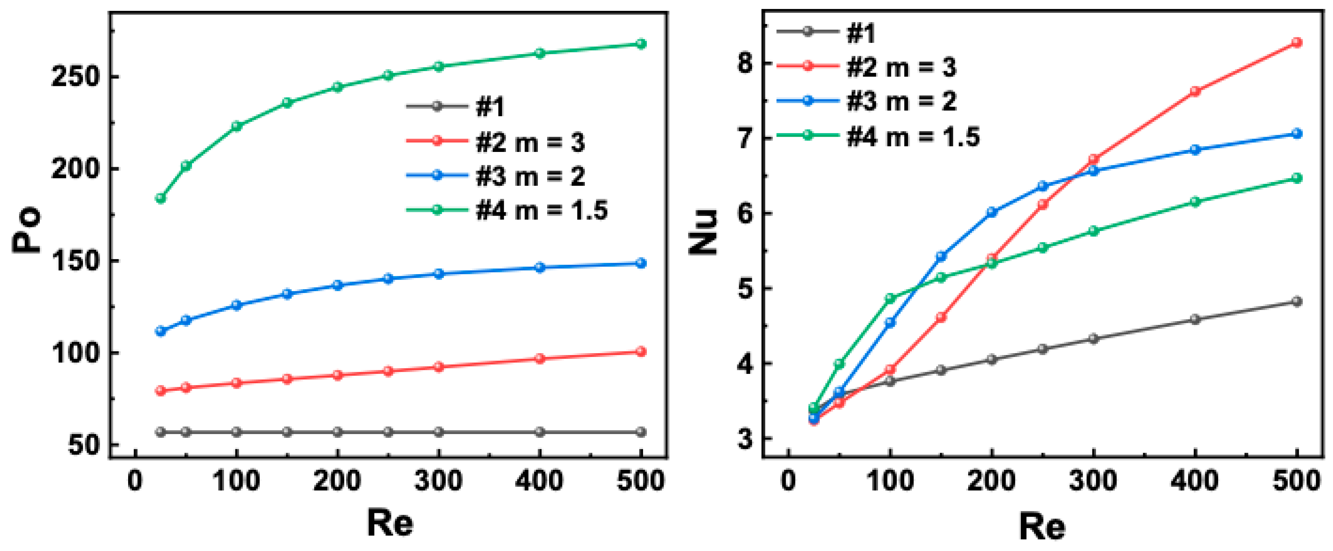
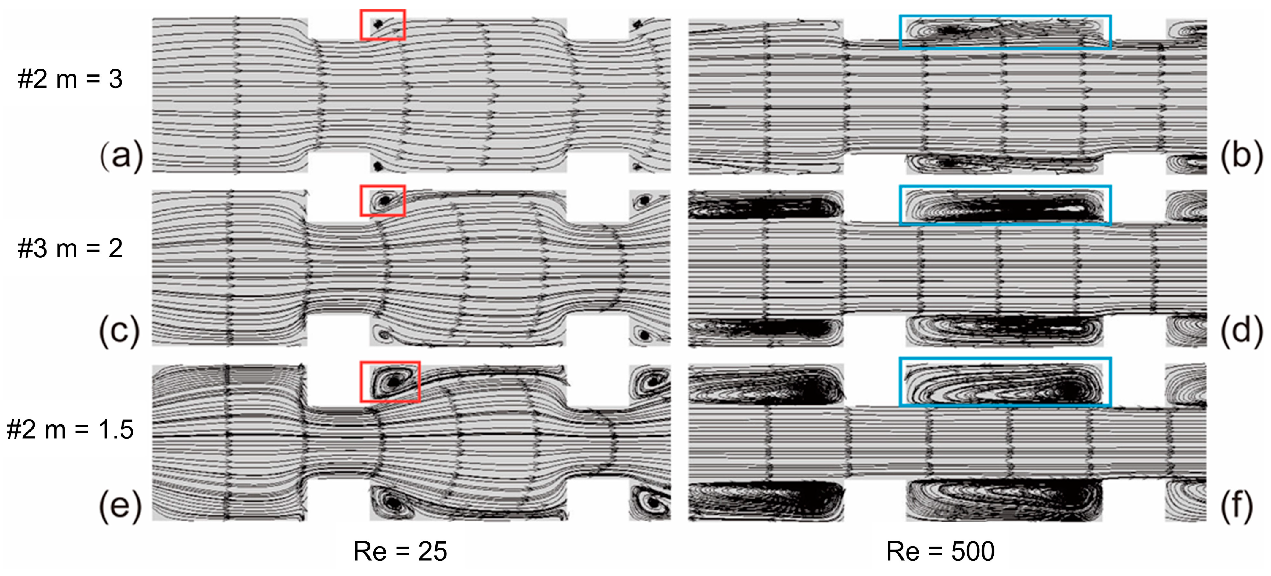
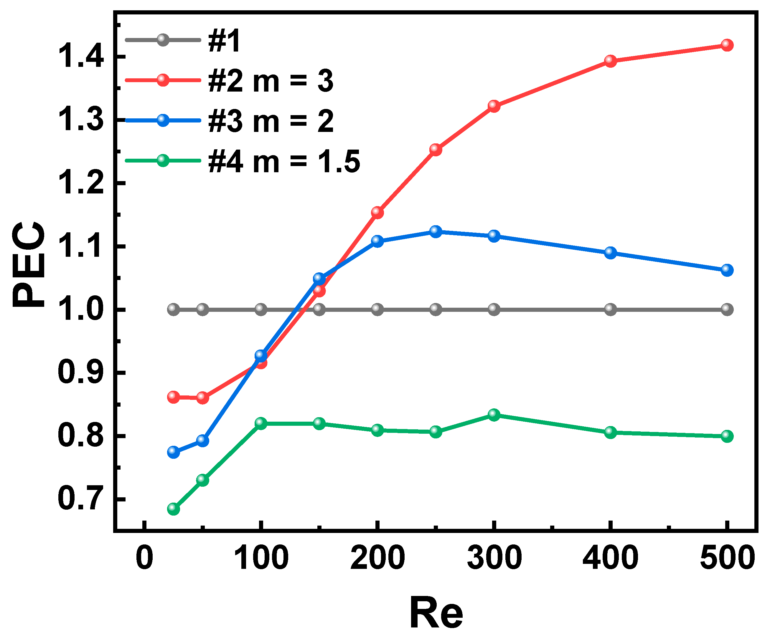
3.1. Aspect Ratio of Fins

As shown in Figure 3, fins influence the flow and heat transfer characteristics of microchannels. Within the scope of this study, the Po in the microchannels with fins was significantly larger than that in channel #1. As shown in Figure 4, vortices are always generated in the microchannels, irrespective of the geometric parameters and working conditions, and as a result, the fins always increase the flow resistance. The effect of Nu on the heat transfer is negligible when Re < 50, because the fluid only slides through the fin intervals, and the boundary layers do not redevelop. As shown in the red box in Figure 4a,c,e, the few vortices formed at the trailing edge of the fin are stagnation vortices, which cannot promote heat exchange. At a large Re, as depicted in the blue box in Figure 4b,d,f, a part of the fluid separates and forms impact vortices under the interference of the fins; this fluid part damages and redevelops the boundary layer. Simultaneously, many hot and cold fluids are mixed, which increases the heat exchange efficiency of the finned microchannel compared to that of channel #1.
The flow characteristics of the finned microchannels with different aspect ratios were investigated as well. For the microchannels with the same Re, the change in Po owing to the fins is negatively correlated with the fin aspect ratio. For example, if the aspect ratio increases from 1.5 to 3, then Po decreases by 35.8% and 48% for Re = 25 and Re = 500. This result is observed because the higher the aspect ratio, the more pronounced the obstruction of the main flow in the channel by the fins and the greater the change in the fluid cross-sectional area. These perturbations result in a higher flow resistance in the microchannels with a higher aspect ratio.
Next, the heat transfer characteristics of the finned microchannels with different aspect ratios were investigated. The difference in Nu is negligible when Re < 50. As is evident from Figure 4a,c,e, the streamlines show that the impact and vortex effects are insignificant, and the velocity of the vortex formed at the trailing edge of the fin is small, which cannot promote heat exchange. As Re increases, Nu of channel #2 increases rapidly and gradually overtakes that of the other cases. As shown in Figure 4b, a smaller rib height results when only a small part of the channel area is occupied; the fluid bypasses the fins and then impacts the surface to produce an efficient heat exchange. As shown in Figure 4f, channel #4, which has a small fin aspect ratio, narrows the effective flow diameter of the channel and deepens the intervals between the fins. This process prevents most fluids from reaching the surface of the intervals and leads to the formation of a large area with small-velocity vortices at the fin interval. These small-velocity vortices do not contribute to the heat transfer. The performance of channel #3 is in between those of channel #1 and #2, as depicted in Figure 4d. Within the scope of this study, the advantage of a large aspect ratio becomes apparent as Re increases.
The aspect ratio of the fin affects the flow and heat transfer characteristics of the microchannel through the channel cross-sectional area and impact vortex effect. As shown in Figure 5, for Re < 100, channel #1 is the best choice. Conversely, for Re > 100, channel #2 is the best, because its large fin aspect ratio results in just slight occupation of the channel area, and the fluid effectively impacts the surface, leading to the destruction and redevelopment of the boundary layer.

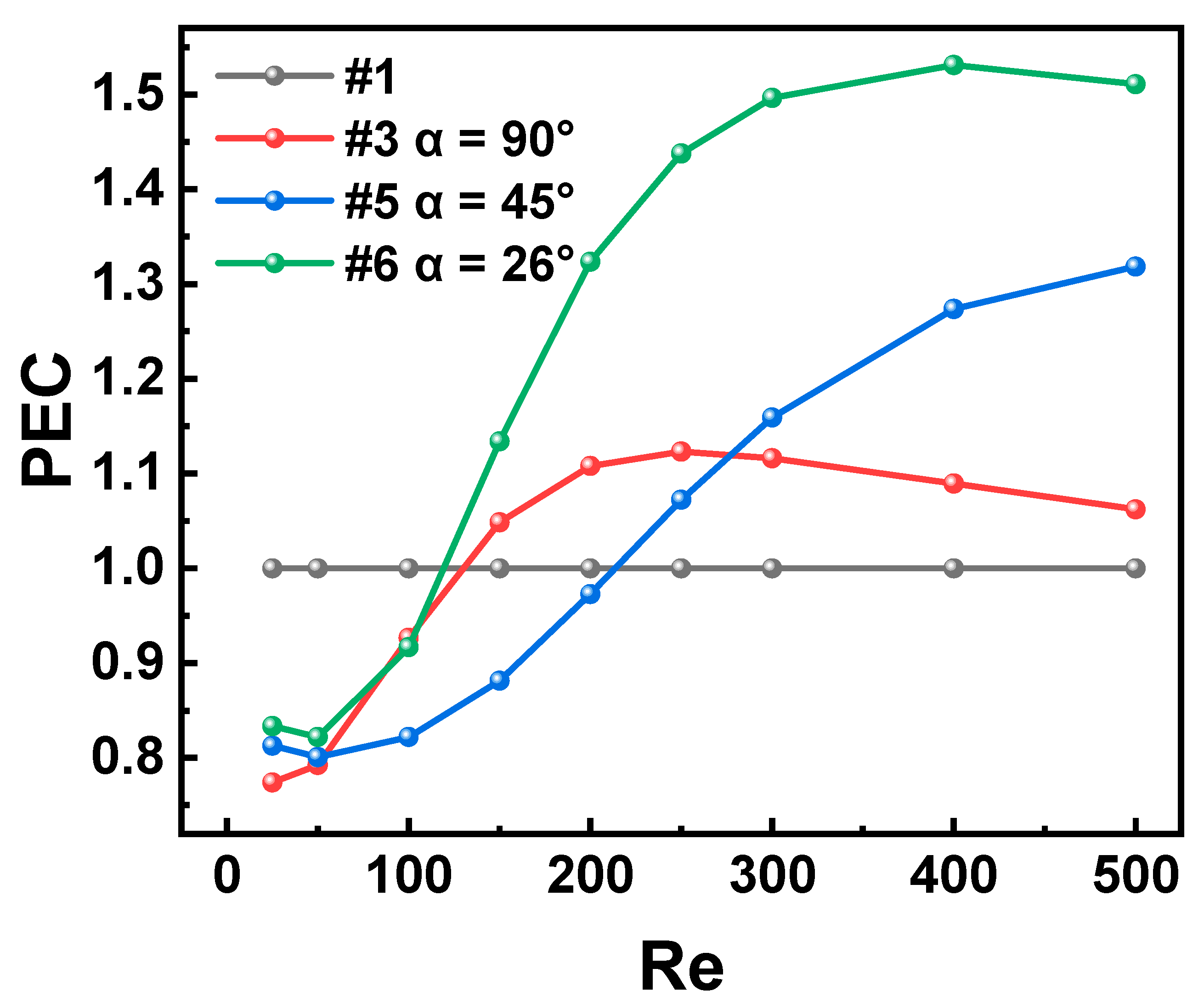
3.2. Incident Angle of Fins

In Figure 6, the flow and heat transfer characteristics of the microchannels are depicted with respect to the incident angle of the fins (α) of #3 (α = 90°), #5 (α = 45°), and #6 (α = 26°).
The flow characteristics of the finned microchannels with different incident angles were evaluated in this study. For the microchannels with the same Re, the change in Po due to the fins is positively correlated with the fin incident angle. For example, if the incident angle increases from 26° to 90°, then Po increases by 24.0% at Re = 25 and by 7.6% at Re = 500. This trend is observed, because a larger incident angle results in a more pronounced obstruction of the main flow in the channel by the fins as well as a greater change in the fluid cross-sectional area and flow direction. The aforementioned perturbations result in a higher flow resistance in the microchannels with a higher incident angle.
Next, we investigated the heat transfer characteristics of the finned microchannels with different incident angles. The difference in Nu is negligible when Re < 50. In Figure 7a,c,e, the streamlines show that the impact and vortex effects are weak, and the velocity of the vortex formed at the trailing edge of the fin is small, which cannot promote heat exchange. As Re is increased, the Nu of channel #6 with a small fin incident angle increases rapidly and then gradually overtakes that in the others. As shown in Figure 7f, the small fin incident angle of channel #6 prevents any significant shifting in the fluid direction, thus avoiding massive stagnation zones. The Nu of channel #3 with a large fin incident angle saturates after increasing for a short time. Figure 7b indicates an unsatisfactory heat transfer efficiency of channel #3, because the large incident angle of the fins tends to stagnate at the trailing edge of the fins, which affects the heat exchange. The performance of channel #6 is in between that of the aforementioned channels as shown in Figure 7d. Within the scope of the study, the advantage of the small incident angle becomes apparent as the Re increases.
The incident angle of the fin affects the flow and heat transfer characteristics of the microchannel by changing the flow direction. Figure 8 reveals that for Re < 100, channel #1 is the best choice, whereas for Re > 150, channel #6 is the best. This is because the small incident angle of channel #6 is favorable for the flow trajectory, and the flow direction at the front edge of the fin does not change significantly, causing stagnation. The boundary layer is effectively broken such that the fluid fully exchanges heat with the wall and thus enhances the heat transfer characteristics.

3.3. Smoothness of Fins

Figure 9 shows the flow and heat transfer characteristics of the microchannels with respect to the smoothness of the fins (n) of #3 (n = 3), #7 (n = 5), and #8 (n =∞).
The flow characteristics of the finned microchannels with different smoothness values were investigated. For the microchannels with the same Re, the change in Po owing to fins is negatively correlated with the fin smoothness. This is because the smoother the fin, the less pronounced the obstruction of the main flow in the channel by the fins and the greater the change in the flow direction. The aforementioned perturbations result in a lower flow resistance in the microchannels with smoother fins.
Next, we evaluated the heat transfer characteristics of the finned microchannels with different smoothness. The difference in Nu is negligible when Re < 50. As shown in Figure 10a,c,e, the streamlines show that the impact and vortex effects are not significant, and the velocity of the vortex formed at the trailing edge of the fin is small, which cannot promote heat exchange. When 50 < Re < 250, Nu of channel #3 with poor smoothness is larger than that of the others. As shown in Figure 10b, the relatively angular shape excites the separation of a large number of fluids and destruction of the boundary layer. As Re increases, Nu of channel #8, which exhibits an excellent smoothness, increases rapidly and then gradually overtakes that of the others. As shown in Figure 10f, the smooth shape of the channel prevents the formation of small-velocity vortex regions. The Nu of channel #3 with poor smoothness saturates after increasing for a certain time. As shown in Figure 10b, the unsatisfactory heat transfer efficiency of channel #3 originates from the shaped corners of the fins, which tend to form a large area of small-velocity vortices at the fin intervals; these vortices are not conducive to heat transfer. The performance of channel #7 is in between those of the aforementioned channels, as is evident from Figure 10d. Within the scope of the study, the advantage of the smoothness becomes apparent as Re increases.
The smoothness of the fin affects the flow and heat transfer characteristics of the microchannel through the destruction of the boundary layer and formation of small-velocity vortices. As shown in Figure 11, for Re < 50, channel #1 is the best choice. For 50 < Re < 250, channel #3 exhibits better characteristics because of the separation of a large number of fluids and destruction of the boundary layer. Channel #8 can be selected when Re > 250, because as the smoothness worsens, many regions with lower velocities are formed at large Re.

4. Conclusions

In this study, numerical simulations were performed to investigate the flow and heat transfer characteristics of microchannels with fins with Re ranging from 0 to 500. Fin structures with different aspect ratios, incident angles, and smoothness were studied, and the results were innovatively summarized into conclusions that can be generalized to other microchannels with fins. We also examined the underlying mechanisms and determined the optimization direction of the fins in the microchannels. The results obtained in this study will be beneficial for electronic and aerospace applications.
The main findings of this study are as follows:
(1)
Fins always increase the flow resistance within the investigated range, although this increase is less than that in the heat transfer.
(2)
Fins do not always promote heat transfer. At low Re, the fluid only slides through the fin intervals, and the boundary layers do not redevelop. Thus, a smooth microchannel without internal microstructures exhibits the best heat transfer characteristics for Re < 100. However, at high Re values, such as Re > 100, microchannels with fins show a better performance. These observations can be attributed to the redevelopment of the boundary layer, separation of the mainstream, formation of vortices, and mixing of the fluids.
(3)
Fins with a high aspect ratio, small incidence angle, and high smoothness showed exceptional performance within the scope of this work. This is because they avoid low-velocity vortex zones owing to flares and sharp corners and simultaneously promote mixing of hot and cold fluids, leading to the destruction and redevelopment of the boundary layer.
(4)
The incidence angle is the most critical structural parameter within the scope of this investigation. It mainly affects the mainstream and boundary layers of the fluid by periodically influencing the cross-sectional area and flow direction of the channel, thereby affecting the flow and heat transfer characteristics.

Author Contributions

Conceptualization, M.L. and P.N.; data curation, M.L.; formal analysis, M.L. and W.F.; funding acquisition, H.L.; investigation, P.N.; methodology, W.F. and J.S.; software, P.N.; validation, M.L., T.X., and W.F.; writing—original draft preparation, M.L; writing—review and editing, T.X. and W.F.; supervision, X.G. and T.X.; project administration, H.L.; funding acquisition, H.L. All authors have read and agreed to the published version of the manuscript.

Funding

This research was funded by the Natural Science Foundation of the Beijing Municipality (grant no. JQ20016), the Key Laboratory Fund of the Pre-Research Management Center, Ministry of Science and Technology (CMC6142702200509), the National Natural Science Foundation of China (grant no. 52006003), and MEMS Permanent Magnet Rotating Motor Technology Applied to Aircraft Power (HKCX2020-02-015).

Institutional Review Board Statement

Not applicable.

Informed Consent Statement

Not applicable.

Data Availability Statement

Not applicable.

Conflicts of Interest

The authors declare no conflict of interest.

References

  1. Khattak, Z.; Ali, H.M. Air Cooled Heat Sink Geometries Subjected to Forced Flow: A Critical Review. Int. J. Heat Mass Transf. 2019, 130, 141–161. [Google Scholar] [CrossRef]
  2. Soleymani, Z.; Rahimi, M.; Gorzin, M.; Pahamli, Y. Performance Analysis of Hotspot Using Geometrical and Operational Parameters of a Microchannel Pin-Fin Hybrid Heat Sink. Int. J. Heat Mass Transf. 2020, 159, 120141. [Google Scholar] [CrossRef]
  3. Kewalramani, G.V.; Hedau, G.; Saha, S.K.; Agrawal, A. Empirical Correlation of Laminar Forced Convective Flow in Trapezoidal Microchannel Based on Experimental and 3D Numerical Study. Int. J. Therm. Sci. 2019, 142, 422–433. [Google Scholar] [CrossRef]
  4. Ghosh, A.; Biswas, S.; Turner, T.; Kietzig, A.-M.; Brochu, M. Surface, Microstructure, and Tensile Deformation Characterization of LPBF SS316L Microstruts Micromachined with Femtosecond Laser. Mater. Des. 2021, 210, 110045. [Google Scholar] [CrossRef]
  5. Li, Q.; Jiang, J.; Hong, Y.; Du, J. Numerical Investigation of Thermal Management Performances in a Solar Photovoltaic System by Using the Phase Change Material Coupled with Bifurcated Fractal Fins. J. Energy Storage 2022, 56, 106156. [Google Scholar] [CrossRef]
  6. Unnikrishnan, U.; Yang, V. A Review of Cooling Technologies for High Temperature Rotating Components in Gas Turbine. Propuls. Power Res. 2022, 11, 293–310. [Google Scholar] [CrossRef]
  7. Shahzad, F.; Jamshed, W.; Safdar, R.; Hussain, S.M.; Nasir, N.A.A.M.; Dhange, M.; Nisar, K.S.; Eid, M.R.; Sohail, M.; Alsehli, M.; et al. Thermal Analysis Characterisation of Solar-Powered Ship Using Oldroyd Hybrid Nanofluids in Parabolic Trough Solar Collector: An Optimal Thermal Application. Nanotechnol. Rev. 2022, 11, 2015–2037. [Google Scholar] [CrossRef]
  8. Hussain, S.M. Dynamics of Radiative Williamson Hybrid Nanofluid with Entropy Generation: Significance in Solar Aircraft. Sci. Rep. 2022, 12, 8916. [Google Scholar] [CrossRef]
  9. Hussain, S.M. Thermal-Enhanced Hybrid of Copper–Zirconium Dioxide/Ethylene Glycol Nanofluid Flowing in the Solar Collector of Water-Pump Application. Waves Random Complex Media 2022, 0, 1–28. [Google Scholar] [CrossRef]
  10. Lee, Y.J.; Singh, P.K.; Lee, P.S. Fluid Flow and Heat Transfer Investigations on Enhanced Microchannel Heat Sink Using Oblique Fins with Parametric Study. Int. J. Heat Mass Transf. 2015, 81, 325–336. [Google Scholar] [CrossRef]
  11. Tuckerman High-Performance Heat-Sinking for VLSI. IEEE Electr Device 1981.
  12. Tao, W.Q.; He, Y.L.; Wang, Q.W.; Qu, Z.G.; Song, F.Q. A Unified Analysis on Enhancing Single Phase Convective Heat Transfer with Field Synergy Principle. Int. J. Heat Mass Transf. 2002, 45, 4871–4879. [Google Scholar] [CrossRef]
  13. İzci, T.; Koz, M.; Koşar, A. The Effect of Micro Pin-Fin Shape on Thermal and Hydraulic Performance of Micro Pin-Fin Heat Sinks. Heat Transf. Eng. 2015, 36, 1447–1457. [Google Scholar] [CrossRef]
  14. Abdoli, A.; Jimenez, G.; Dulikravich, G.S. Thermo-Fluid Analysis of Micro Pin-Fin Array Cooling Configurations for High Heat Fluxes with a Hot Spot. Int. J. Therm. Sci. 2015, 90, 290–297. [Google Scholar] [CrossRef]
  15. Guo, D.; Gao, J.; Santhanam, S.; Yao, S.C. Experimental Investigation of Laminar Flow across Short Micro Pin Fin Arrays. J. Micromechanics Microengineering 2014, 24, 095011. [Google Scholar] [CrossRef]
  16. Wang, H.; Fu, T.; Wang, J.; Zhang, F.; Zhang, K.; Deng, X. Study on Heat Transfer Performance of Fin-and-Tube Heat Exchanger with Elliptical Fins. J. Energy Storage 2022, 56, 105956. [Google Scholar] [CrossRef]
  17. Limbasiya, N.; Roy, A.; Harichandan, A.B. Numerical Simulation of Heat Transfer for Microelectronic Heat Sinks with Different Fin Geometries in Tandem and Staggered Arrangements. Therm. Sci. Eng. Prog. 2017, 4, 11–17. [Google Scholar] [CrossRef]
  18. kang, ning; wu, huiying; xu, fayao Flow and heat transfer characteristics in Silicon-Based Pin-Fin Microchannels. J. Eng. Thermophys. 2015, 36, 1572–1577.
  19. Jia, Y.; Xia, G.; Li, Y.; Ma, D.; Cai, B. Heat Transfer and Fluid Flow Characteristics of Combined Microchannel with Cone-Shaped Micro Pin Fins. Int. Commun. Heat Mass Transf. 2018, 92, 78–89. [Google Scholar] [CrossRef]
  20. Li, H.; Li, Y.; Huang, B.; Xu, T. Numerical Investigation on the Optimum Thermal Design of the Shape and Geometric Parameters of Microchannel Heat Exchangers with Cavities. Micromachines 2020, 11, 721. [Google Scholar] [CrossRef] [PubMed]
  21. Huang, B.; Li, H.; Xu, T. Experimental Investigation of the Flow and Heat Transfer Characteristics in Microchannel Heat Exchangers with Reentrant Cavities. Micromachines 2020, 11, 403. [Google Scholar] [CrossRef] [Green Version]
  22. Huang, B.; Li, H.; Xia, S.; Xu, T. Experimental Investigation of the Flow and Heat Transfer Performance in Micro-Channel Heat Exchangers with Cavities. Int. J. Heat Mass Transf. 2020, 159, 120075. [Google Scholar] [CrossRef]
  23. Zhu, L.; Awais, M.; Javed, H.M.A.; Mustafa, M.S.; Tlili, I.; Khan, S.U.; Safdari Shadloo, M. Photo-Catalytic Pretreatment of Biomass for Anaerobic Digestion Using Visible Light and Nickle Oxide (NiOx) Nanoparticles Prepared by Sol Gel Method. Renew. Energy 2020, 154, 128–135. [Google Scholar] [CrossRef]
  24. Parvin, S.; Isa, S.S.P.M.; Duais, F.S.A.-; Hussain, S.M.; Jamshed, W.; Safdar, R.; Eid, M.R. The Flow, Thermal and Mass Properties of Soret-Dufour Model of Magnetized Maxwell Nanofluid Flow over a Shrinkage Inclined Surface. PLOS ONE 2022, 17, e0267148. [Google Scholar] [CrossRef]
  25. Hussain, S.M. Irreversibility Analysis of Time-Dependent Magnetically Driven Flow of Sutterby Hybrid Nanofluid: A Thermal Mathematical Model. Waves Random Complex Media 2022, 0, 1–33. [Google Scholar] [CrossRef]
  26. Sajid, T.; Jamshed, W.; Safdar, R.; Hussain, S.M.; Shahzad, F.; Bilal, M.; Rehman, Z.; Rahman, M.M.; Pasha, A.A. Features and Aspects of Radioactive Flow and Slippage Velocity on Rotating Two-Phase Prandtl Nanofluid with Zero Mass Fluxing and Convective Constraints. Int. Commun. Heat Mass Transf. 2022, 136, 106180. [Google Scholar] [CrossRef]
  27. Madhu, M.; Mahanthesh, B.; Shashikumar, N.S.; Shehzad, S.A.; Khan, S.U.; Gireesha, B.J. Performance of Second Law in Carreau Fluid Flow by an Inclined Microchannel with Radiative Heated Convective Condition. Int. Commun. Heat Mass Transf. 2020, 117, 104761. [Google Scholar] [CrossRef]
  28. Batchelor, C.K.; Batchelor, G.K. An Introduction to Fluid Dynamics, 1st ed.; Cambridge University Press: Cambridge, UK, 1967. [Google Scholar]
  29. Xu, B.; Ooti, K.T.; Wong, N.T.; Choi, W.K. Experimental Investigation of Flow Friction for Liquid Flow in Microchannels. Int. Commun. Heat Mass Transf. 2000, 27, 1165–1176. [Google Scholar] [CrossRef]
  30. Rapp, B.E. Microfluidics: Modeling, Mechanics and Mathematics. In Microfluidics: Modelling, Mechanics and Mathematics; Rapp, B.E., Ed.; Micro and Nano Technologies; Elsevier: Oxford, UK, 2017; p. xxxi. ISBN 978-1-4557-3141-1. [Google Scholar]
  31. Judy, J.; Maynes, D.; Webb, B.W. Characterization of Frictional Pressure Drop for Liquid Flows through Microchannels. Int. J. Heat Mass Transf. 2002, 45, 3477–3489. [Google Scholar] [CrossRef]
  32. Qu, W.; Mudawar, I. Experimental and Numerical Study of Pressure Drop and Heat Transfer in a Single-Phase Micro-Channel Heat Sink. Int. J. Heat Mass Transf. 2002, 45, 2549–2565. [Google Scholar] [CrossRef]
  33. Alfellag, M.A.; Ahmed, H.E.; Fadhil, O.T.; Kherbeet, A.S. Optimal Hydrothermal Design of Microchannel Heat Sink Using Trapezoidal Cavities and Solid/Slotted Oval Pins. Appl. Therm. Eng. 2019, 158, 113765. [Google Scholar] [CrossRef]
  34. Zhang, M.; Wu, S.; Ma, Q. The Calculation of Heat Transfer in Duct Flow by Unstructured Grids. J. Nanjing Inst. Technol. Nat. Sci. Ed. 2006, 4, 25. [Google Scholar] [CrossRef]
Figure 1. Schematic of the microchannels. All the surfaces are adiabatic except the solid–liquid contact surface and heating surface at the bottom of the solid. The top surface of the fluid domain is closed and does not allow any mass or heat transfer. A constant heat flux density of 30000 W/m2 is applied on the bottom surface of the solid. The structural parameters (mm) are H = 0.5, L = 40, W = 1, Lin = 0.8, Lout = 1.02, h = 0.3, w = 0.3, ls = 0.5, and lf = 0.12.
Machines 11 00154 g001
Figure 2. Schematic illustration of the microchannels and fins with different aspect ratios, incident angles, and smoothness values.
Machines 11 00154 g002
Figure 3. Po and Nu versus Re with different fin aspect ratios (m).
Machines 11 00154 g003
Figure 4. Streamlines in the transverse central section of the fluid with different fin aspect ratios: (a) m = 3, Re = 25; (b) m = 3, Re = 500; (c) m = 2, Re = 25; (d) m = 2, Re = 500; (e) m = 1.5, Re = 25; (f) m = 1.5, Re = 500. The red box indicates the stagnation vortices formed at the trailing edge of the fins at Re = 25, and the blue box indicates the impact vortices formed in the intervals between fins at Re = 500.
Machines 11 00154 g004
Figure 5. PEC versus Re with different fin aspect ratios.
Machines 11 00154 g005
Figure 6. Po and Nu versus Re with different fin incident angles.
Machines 11 00154 g006
Figure 7. Streamlines in the transverse central section of the fluid with different fin incident angles: (a) α = 90°, Re = 25; (b) α = 90°, Re = 500; (c) α = 45°, Re = 25; (d) α = 45°, Re = 500; (e) α = 26°, Re = 25; (f) α = 26°, Re = 500.
Machines 11 00154 g007
Figure 8. PEC versus Re with different fin incident angles.
Machines 11 00154 g008
Figure 9. Po versus Re with different fin smoothness.
Machines 11 00154 g009
Figure 10. Streamlines in the transverse central section of the fluid with different fin smoothness: (a) n = 3, Re = 25; (b) n = 3, Re = 500; (c) n = 5, Re = 25; (d) n = 5, Re = 500; (e) n = ∞, Re = 25; (f) n = ∞, Re = 500.
Machines 11 00154 g010
Figure 11. PEC versus Re with different fin smoothness.
Machines 11 00154 g011
Table 1. Geometrical parameters of the fins.
lslf lh αmn
#1------
#20.5 mm0.12 mm0.04 mm90°33
#30.5 mm0.12 mm0.06 mm90°23
#40.5 mm0.12 mm0.08 mm90°1.53
#50.5 mm0.12 mm0.06 mm45°23
#60.5 mm0.12 mm0.06 mm26°23
#70.5 mm0.12 mm0.06 mm90°25
#80.5 mm0.12 mm0.06 mm90°2
Table 2. Thermophysical properties at room temperature and atmospheric pressure; these properties were used in the calculations.
ParameterSymbolValue
Deionized
water
Densityρf998.2 kg/m3
Dynamic viscosityμf0.001003 kg/(m·s)
Specific heatCpf4182 J/(kg·K)
Thermal conductivitiesλf0.6 W/(m·K)
SiliconThermal conductivitiesλs18.5 W/(m·K)
Table 3. Results of simulation validation.
No.Number of GridsNue (Nu)Poe (Po)
13,156,7963.2240110.50%91.927361.63%
25,751,4243.2126550.14%92.444891.08%
310,698,1683.2076880.01%92.874070.62%
418,773,4903.2076160.01%93.179410.29%
533,945,0903.2075720.01%93.338820.12%
658,475,0883.208021-93.45025-
Table 4. Results of model verification.
RePoDeviation Value
2556.75550.254%
5056.75550.254%
10056.755470.254%
15056.755470.254%
20056.758840.248%
25056.755450.254%
30056.755450.254%
40056.753820.257%
50056.755710.254%
Disclaimer/Publisher’s Note: The statements, opinions and data contained in all publications are solely those of the individual author(s) and contributor(s) and not of MDPI and/or the editor(s). MDPI and/or the editor(s) disclaim responsibility for any injury to people or property resulting from any ideas, methods, instructions or products referred to in the content.

