Article

A Toolpath Planning Method for Optical Freeform Surface Ultra-Precision Turning Based on NURBS Surface Curvature

1
School of Mechatronics Engineering, Harbin Institute of Technology, Harbin 150001, China
2
Department of Mechanical and Aerospace Engineering, Brunel University London, Uxbridge UB8 3PH, UK
*
Authors to whom correspondence should be addressed.
Machines 2023, 11(11), 1017; https://doi.org/10.3390/machines11111017
Submission received: 20 September 2023 / Revised: 19 October 2023 / Accepted: 3 November 2023 / Published: 9 November 2023
(This article belongs to the Special Issue Precision Engineering in Manufacturing: Challenges and Future)

Abstract

:
As the applications for freeform optical surfaces continue to grow, the need for high-precision machining methods is becoming more and more of a necessity. Different toolpath strategies for the ultra-high precision turning of freeform surfaces can have a significant impact on the quality of the machined surfaces. This paper presents a novel toolpath planning method for ultra-precision slow tool servo diamond turning based on the curvature of freeform surfaces. The method analyzes the differential geometric properties of freeform surfaces by reconstructing NURBS freeform surfaces. A mathematical model is constructed based on the parameters of different positions of the freeform surface, toolpath parameters, and tool residual height. Appropriate toolpath parameters can be calculated to generate the optical freeform ultra-precision slow tool servo diamond turning toolpath. Compared with the toolpaths generated by the traditional Archimedes spiral method, the ultra-precision slow tool servo diamond turning toolpath planning method proposed in this paper can generate more uniform toolpaths on the freeform surfaces and keep the residual tool height within a small range.

1. Introduction

Freeform surfaces are a class of complex surfaces with non-rotational symmetry and irregular shapes and are often difficult to describe by equations. Compared to traditional optical surfaces, freeform optical surfaces can provide more design freedom, improve the optical performance of individual optical components and optical systems, and eliminate spherical aberration, astigmatism, coma, chromatic aberration, and other aberrations [1]. They also simplify the optical system structure by reducing the number of optical components in the optical system [2]. As a result, they are widely used in optical imaging systems [3,4,5,6,7,8] and non-imaging systems [9,10,11,12,13]. The development of ultra-precision machining technology has provided many creative challenges for the construction of high-precision optical freeform surfaces [14,15,16,17].
However, for optical freeform surfaces with complex surface shapes, the traditional toolpath planning method has problems, such as large machining errors and difficult control of machining quality when applied to ultra-precision turning [18,19]. Therefore, there is an urgent need to develop a toolpath planning method for freeform ultra-precision diamond turning to improve the high-precision manufacturing of complex optical freeform parts.
There are potential challenges in realizing the fabrication of freeform surfaces through ultra-precision machining technology [20,21]. Balabokhin et al. proposed a method to generate an iso-scallop and contour-parallel toolpath for the freeform surface in three-axis CNC milling [22]. Takasugi et al. proposed a method for generating a spiral curve in the parametric domain. This method can be applied to surfaces consisting of multiple patches [23]. Sato et al. used different methods to generate control point clouds, optimize toolpaths, and improve the machining quality of 2D sine waves and microlens arrays [24]. Wang et al. proposed an adaptive toolpath planning method for ultra-precision turning, which reduces the fluctuation of feed direction and ensures the surface quality of large-aperture optical freeform surfaces [25]. Zhang et al. proposed a position-optimized off-axis ultra-precision turning technology for machining large-aspect-ratio rectangular freeform surfaces [26]. Zhang et al. created a novel machining system featuring a spindle with an integrated assembly of roughing and precision cutting tools, designed to cut freeform prisms [27]. Lang et al. propose an ultra-precision turning based on hybrid slow–fast tool servoing, which improves the machining efficiency of freeform surfaces by decomposing freeform surfaces to run STS and FTS simultaneously [28]. Cheng et al. carried out research on an automatic dynamics analysis of mechanical systems, including the dynamic and kinematic factors, and proposed a toolpath method based on machine tool kinematics and dynamics [29]. The Archimedes spiral method is widely used to generate toolpaths for ultra-precision machining. Zuo et al. proposed a toolpath planning method for ultra-precision turning of freeform surfaces using non-zero rake angle tools and constructed a morphology prediction model for the ultra-precision turning of freeform surfaces [30]. Zhou et al. used the constant arc length strategy to sample an Archimedes helix to generate toolpaths and proposed a tool tip radius compensation method to improve the contour accuracy of the machined surface [31]. Yi et al. proposed a diamond toolpaths generation method that can make 5 × 5 microlens arrays on ultra-precision diamond lathes [32]. Fang proposed a cylindrical coordinate machining method using NURBS to describe freeform surfaces using Newton’s method to determine the points of the toolpath on NURBS surfaces [33]. Yin et al. used an Archimedes helix to generate toolpaths to machine off-axis aspheric surfaces and compensate for tool centering errors [34]. Cai et al. propose a toolpath planning method for multi-degree-of-freedom FTS. The active control accuracy model is established, and the sampling interval and side feed are automatically calculated according to the maximum allowable error [35]. Zhang et al. used the Archimedes spiral method to generate a toolpath and realized the ultra-precision turning of sinusoidal surfaces in cylindrical coordinates [36]. Zhu et al. proposed a novel adaptive tool servo for the fabrication of complex freeform optical surfaces through analysis of the local curvature along both forward-cutting and side-feeding directions [37]. Li et al. present the design of a near-rotational freeform surface with a low non-rotational degree to constrain the variation of traditional freeform optics to the fabrication of freeform optics on IR materials [38].
However, for optical freeform surfaces, the curvature of each position of the surface is different due to its characteristics, such as non-rotational symmetry and irregular topography. Therefore, when the Archimedes spiral projection is applied to optical freeform machining, the toolpath will be distorted at different positions on the surface, which will lead to deterioration of the machined surface quality [39,40,41,42].
In the research of the above scholars, the ultra-precision machining method of freeform surfaces has been investigated widely. However, the above studies do not have the method of toolpath planning directly along the surface of the surface. Further studies on the tool residual height and surface quality of the traditional Archimedean helix method in freeform ultra-precision slow tool servo diamond turning of freeform surfaces are lacking. Due to the complexity of freeform surfaces, toolpath planning directly along the surface of freeform surfaces requires a study of the geometric differential properties of freeform surfaces to establish the relationship between surface properties and ultra-precision slow-turning servo diamond-turning toolpaths.
In this study, a novel toolpath planning method based on the curvature of NURBS surfaces is proposed for the ultra-precision slow tool servo diamond turning of optical freeform surfaces. By reconstructing the freeform surface, the expression of the freeform surface is obtained, and then the differential geometric properties of the freeform surface can be analyzed. A mathematical model between surface parameters, tool parameters, and residual height is established, and suitable toolpath parameters are calculated. The toolpath for generating ultra-precision slow tool servo diamond turning along the surface of the freeform surface is creatively proposed. The correctness of the toolpath planning method based on the curvature of NURBS surfaces is verified by simulation. Ultra-precision diamond turning tests are carried out to demonstrate that the method can stabilize the tool residual height to a small magnitude.

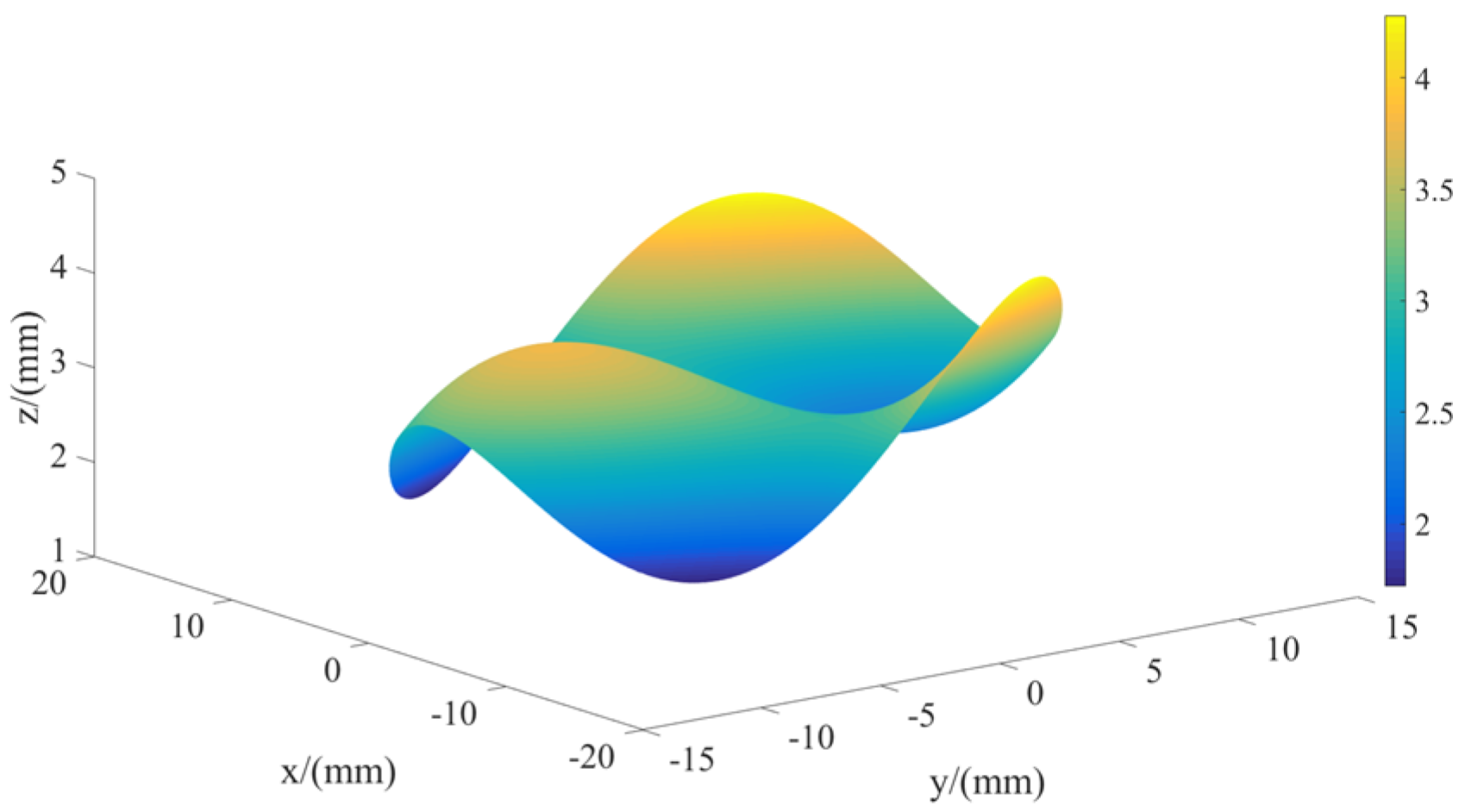
2. Reconstruction of the NURBS Surfaces

Optical freeform surfaces pose challenges in their description and machining due to their limited expressibility. Consequently, a meticulous inquiry into the differential geometric characteristics of freeform surfaces is essential in ultra-precision machining. By reconstructing a NURBS surface, a computable and analyzable expression of freeform surfaces can be obtained.
NURBS has gained prominence as a standard for representing surfaces in computer-aided design. It describes a thorough mathematical technique for representing both analytical and organic surfaces while maintaining numerical stability throughout the computational process [43].
Freeform surfaces can be reconstructed by applying NURBS global interpolation to (n + 1) × (m + 1) discrete data points Q k , l . The equation of the (p,q)-th order for the NURBS surface expression is provided as follows:
Q k , l = S ( u ¯ k , v ¯ l ) = i = 0 n j = 0 m N i , p ( u ¯ k ) N j , q ( v ¯ l ) P i , j
where { P i , j } represents the control point. u ¯ k and v ¯ l denote the parameter values of the discrete data point Q k , l , respectively. Furthermore, N i , p ( u k ) and N j , q ( v l ) describe the p-order and q-order B spline basis functions, which are defined on the non-uniform node vectors U and V, respectively. The node vectors U and V correspond to Equations (2) and (3).
U = { 0 , , 0 ,   u p + 1 , , u n p 1 ,   1 , , 1 }
V = { 0 , , 0 ,   v q + 1 , , v m q 1 ,   1 , , 1 }
The chord length parameter method is employed to parameterize the freeform discrete data point Q k , l .
The parametric calculation process for determining U direction data points u ¯ k is demonstrated in Equations (4)–(6). First, for each l   ( l = 0 ,   1 , , m ) , u ¯ 0 l , u ¯ 1 l , , u ¯ n l are calculated by Equations (4) and (5). The total chord length of the curve in the V direction is denoted as d.
u ¯ 0 l = 0 u ¯ n l = 1 u ¯ k l = u ¯ k 1 l + Q k Q k 1 d ,   k = 1 ,   2 , , n 1
d = k = 1 n Q k Q k 1
A series of parameter values u ¯ 0 l , u ¯ 1 l , , u ¯ n l is computed and then averaged according to Equation (6) to obtain the global parameters of the surface in the U direction. The global parameter in the U direction of the surface can be obtained by iterating through each value l   ( l = 0 ,   1 , , m ) . Based on the same calculation, we can calculate v ¯ l of the surface in the V direction by Equation (7).
  u ¯ k = 1 m + 1 l = 0 m u ¯ k l ,   k = 0 ,   1 , , n
v ¯ l = 1 n + 1 k = 0 n v ¯ l k ,   l = 0 ,   1 , , m
The node vectors ( u p + 1 , , u r p 1 ) of U and ( v q + 1 , , v s q 1 ) of V are calculated following Equations (8) and (9). The results of the parameterization of discrete data Q k , l and the direction of parameter distribution on the NURBS surface are shown in Figure 1.
u a + p = 1 p i = a a + p 1 u ¯ i ,   a = 1 ,   2 , , n p
v b + q = 1 q i = b b + q 1 v ¯ i ,   b = 1 ,   2 , , m q
To determine the values of the non-zero basis functions { N i , p ( u k ) } and { N j , q ( v l ) } in diverse node intervals, the value of { N i , p ( u k ) } can be obtained through the iterative calculation of Equations (10) and (11). Similarly, the solution process for { N j , q ( v l ) } can be completed using a comparable method.
N i , p ( u ) = 1 , u i u u i + 1 0 , o t h e r
N i , p ( u ) = u u i u i + p u i N i , p 1 ( u ) + u i + p + 1 u u i + p + 1 u i + 1 N i + 1 , p 1 ( u )
The control point { P i , j } can be determined once the solution to the basis functions has been found. Equation (1) describes a set of equations with coefficient matrices of (n + 1) × (m + 1) for ( u ¯ k , v ¯ l ) . Upon being transformed into Equation (12), the NURBS curve interpolation methods can be applied to calculate the control point { P i , j } .
Q k , l = S ( u ¯ k , v ¯ l ) = i = 0 n N i , p ( u ¯ k ) j = 0 m N j , q ( v ¯ l ) P i , j = i = 0 n N i , p ( u ¯ k ) T i , j
For l ( l = 0 ,   1 , , m ) , the parameter u ¯ k and node vector U are used to interpolate the NURBS curve of the type value point Q 0 , l , Q 1 , l , , Q n , l m + 1 times, respectively, and the T i , 0 , T i , 1 , , T i , m is inversely obtained. Then, k = 0 ,   1 , , n uses T i , 0 , T i , 1 , , T i , m as the type value point of the interpolation function and interpolates the NURBS curve of n + 1 degree with the parameter v ¯ l and the node vector V so as to reverse the final control point matrix P. The control point matrix is substituted into the NURBS surface parametric equation. The reconstructed optical freeform surface is shown in Figure 2.

3. Toolpath Planning Method for Freeform Surfaces Based on NURBS Surface Curvature

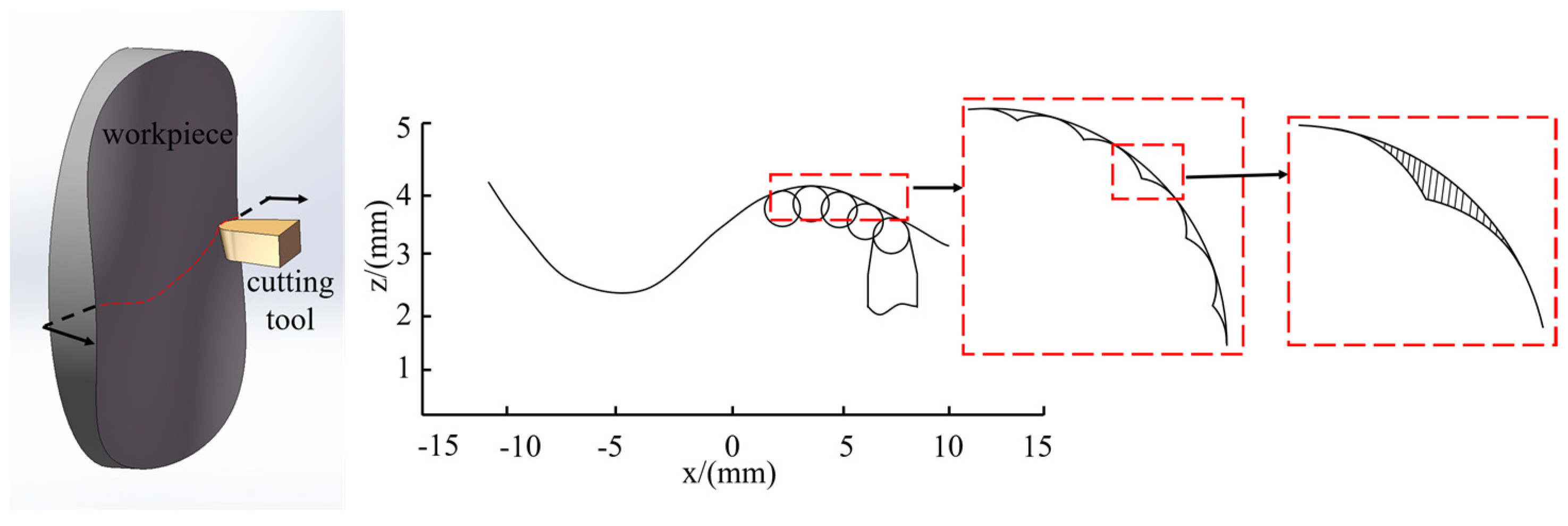
3.1. The Archimedes Spiral Method

The typical configuration for the ultra-precision slow tool servo diamond turning machine is shown in Figure 3. The X and Z axes are positioned in a T-shape, with the spindle (C-axis) situated on the X-axis. The workpiece is clamped with a vacuum suction cup that is attached to the spindle, while the tool is fixed on the Z-axis tool holder. Toolpaths are created through the connection of the X, Z, and C axes as the spindle shifts from speed control mode to position control mode (C-axis mode). The process allows for the removal of workpiece material, enabling ultra-precision turning of non-rotational, symmetric optical freeform surfaces.
The first step in performing ultra-precision slow tool servo-turning on freeform surfaces using tool trajectories created by Archimedean helical projection is a helical trajectory generated in a reference plane, followed by a set of unique points captured on the helical trajectory. The second step is to map the collected points to the surface to be machined. Subsequently, the mapped points are plotted on the freeform surface. Finally, the mapped points are compensated for the tool radius to generate the turning tool trajectory. Figure 4 illustrates this process.
However, projecting the helical path from the base plane to the freeform surface causes distortion due to the non-rotational symmetry and irregular morphology of the latter. This will lead to unequal spacing in machining rows of the resulting toolpaths, resulting in significant errors. Hence, it is crucial to account for these distortions during the machining process. As shown in Figure 5, L i , j refers to the pitch of the helix path generated by the base plane, while L i , j is the machining row spacing of the toolpath. It should be noted that L i , j is not equivalent to L i , j . Variations in the curvature of the freeform surface lead to changes in processing error, which can result in reduced uniformity and machining quality of the surface.

3.2. Calculation of Toolpath Parameters Base on Analysis of NURBS Surfaces

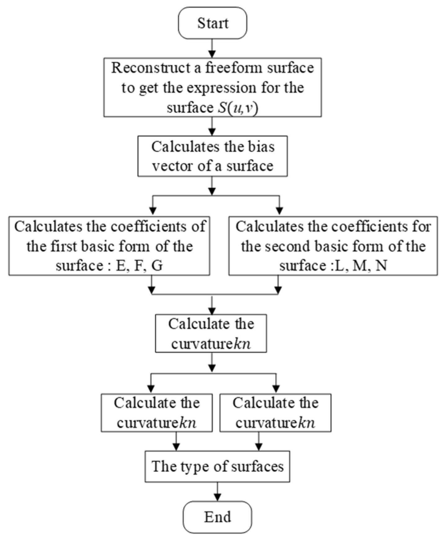
3.2.1. Analysis of NURBS Surfaces

Considering the problems associated with the Archimedean spiral method, this paper presents a novel toolpath planning method for ultra-precision slow tool servo diamond turning of freeform surfaces. It involves analyzing the local curvature of the freeform surface, calculating the curvature at different locations, constructing a mathematical model between the toolpath parameters, the machining parameters, and the residual height, and selecting the appropriate toolpath parameters. This method will result in a more uniform and consistent toolpath on the machined surface. This allows the residual height to be controlled within a small range.
First, the local shape of the freeform surface needs to be determined, and the local bending cases of the freeform surface can be classified into planar, convex, and concave surfaces. Then, the curvature of the surface is calculated according to the theory of differential geometry, and finally, the machining row spacing is calculated. For a freeform surface S(u, v), the partial orientation vector can be determined by calculating the derivative of its basis function, as shown in Equation (13).
k + 1 k u l v S ( u , v ) = i = 0 n j = 0 m N i , p ( k ) N j , q ( l ) P i , j
The normal curvature k n at a point of the free surface represents the projection of the curvature of the curve passing through that point in the normal direction of the surface, as shown in Equation (14).
k n = k cos θ = L d u 2 + 2 M d u d v + N d v 2 E ( d u ) 2 + 2 F d u d v + G ( d v ) 2 = ϕ 2 ϕ 1
where φ 1 denotes the first fundamental form of the surface, and E, F, and G are the coefficients of the first fundamental form. φ 2 denotes the second fundamental form of the surface, and L, M, and N are the coefficients of the second fundamental form.
H is the mean curvature of the surface and K is the Gaussian curvature of the surface, as shown in Equations (15) and (16).
H = E N 2 F M G L 2 ( E G F 2 )
K = L N M 2 E G F 2
Based on the positive and negative values of the mean curvature and Gaussian curvature, the types of points at different locations on the freeform surface can be determined. The freeform surface is continuously changing, and thus the type of the local area of the surface around the point can be further determined based on the discrimination shown in Figure 6.

3.2.2. Calculation of Toolpath Parameters

Based on the results of the local area analysis of the freeform surface, Figure 7a depicts the contact between the surface and the tool. A mathematical model has been formulated for different contact types, elucidating the correlation between the tool radius R, residual height h, radius of the curvature Rn of the contact point, and machining row distance L concerning various surface contact areas.
When the surface surrounding the contact point of the tool and machining surface is flat, as depicted in Figure 7b, the radius of the curvature Rn of the contact point in the radial direction may be regarded as infinite. The mathematical model linking the tool radius R, the residual height h, and the machining row distance L is shown in Equation (17).
L 2 2 R h
where the surface surrounding the contact point of the tool and machining surface is convex, as depicted in Figure 7c. The mathematical model linking the tool radius R, the residual height h, and the machining row distance L is shown in Equation (18).
L 2 2 R h R n R n + R
where the surface surrounding the contact point of the tool and machining surface is flat, as depicted in Figure 7d. The mathematical model linking the tool radius R, the residual height h, and the machining row distance L is shown in Equation (19).
L 2 2 R h R n R n R
Based on the mathematical model established by the surface analysis above, the calculation of machining row spacing can be performed. A grid consisting of n × m points is chosen on the freeform surface S(u, v) in the U and V directions. The allowable machining row spacing for each point along the radial direction is then determined at the identical residual height h, according to the type of surface in proximity to each point. The outcome is denoted as L 1 , 1 , L 1 , 2 , , L n , m . In areas where the curvature of the freeform surface varies significantly, the calculation process can be reiterated to confirm the outcomes. Subsequently, the minimum row width for machining in the radial direction of the freeform surface can be determined as L = L m i n .

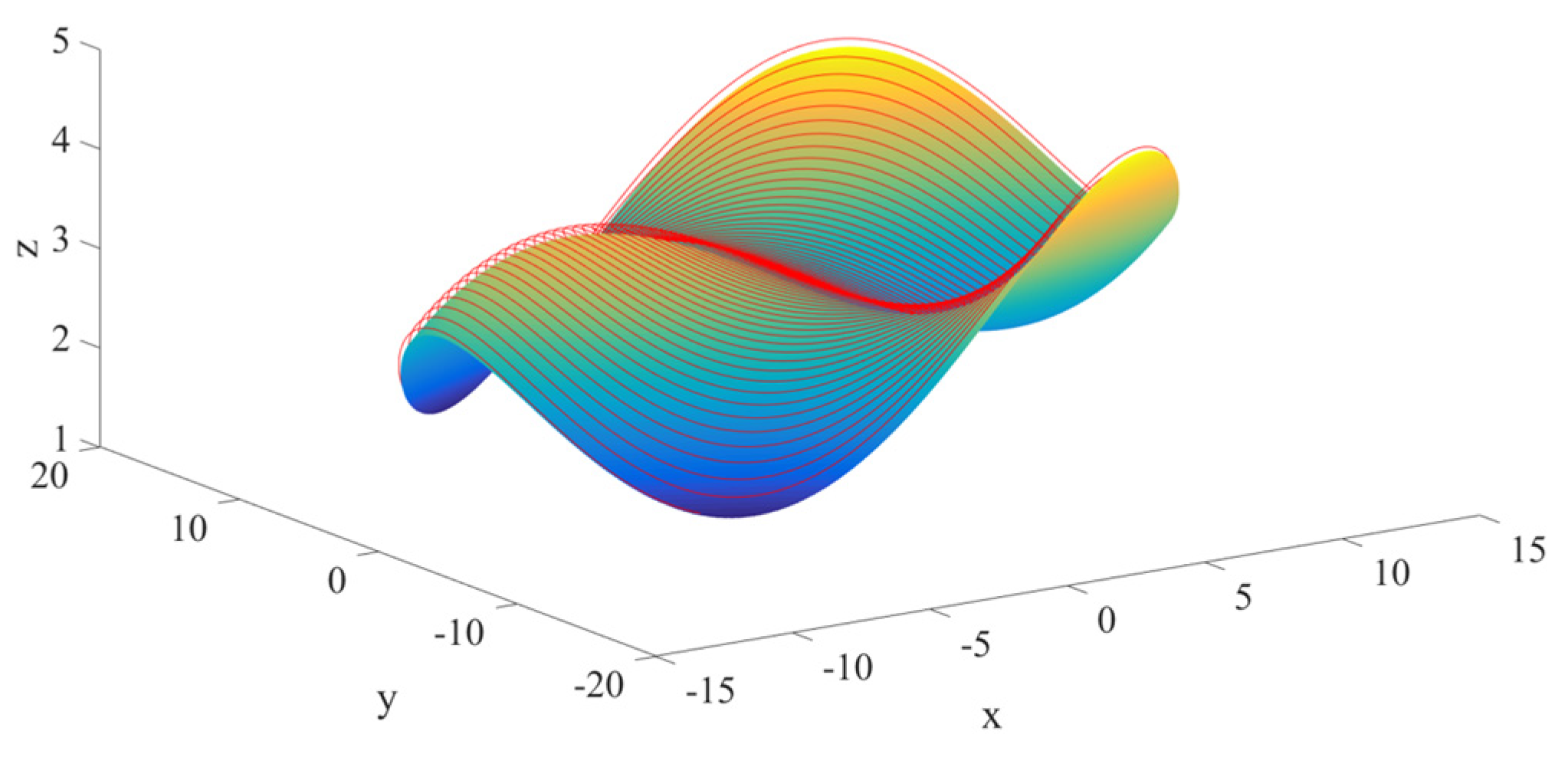
3.3. Toolpath Based on NURBS Surface Curvature

Toolpath planning for ultra-precision slow tool servo diamond turning based on NURBS surface curvature consists of two steps. First, the circumferential discrete point is taken by the equal angle method so that the angle between the two adjacent points along the circumferential spiral on the surface and the center line of the surface is consistent to generate the discrete point data. Second, with L = L m i n as the machining row spacing along the radial direction, the tool contact point of freeform ultra-precision slow tool servo diamond turning is gradually determined along the radial direction of the surface by the recursive method.
The calculated tool contact points (u, v) can be converted by Equation (20) to tool contact points ( x n , y n , z n ) in Cartesian coordinates.
( x n , y n , z n ) = Q n = S ( u i , v j )
In the process of ultra-precision slow tool servo diamond turning, the position of the contact point between the diamond tool and the freeform surface is constantly changing, as shown in Figure 8. The point Qi,j is the contact point between the diamond tool and the surface, and the point Pi,j is the center point of the radius of the diamond tool tip circle. However, Qi,j cannot be directly applied to machining programs on ultra-precision machines. Therefore, tool contacts need to be converted to tool arc center points by means of tool compensation.
Tool compensation is carried out for the tool contact point Qi,j ( x i j , y i j , z i j ) . The direction of compensation is the normal vector of the tool contact point along the front tool surface projection direction, and the compensation amount is the arc radius R of the diamond tool, as shown in Figure 9. The components of the compensation quantity in the x and z directions are calculated in Equations (21) and (22).
x i = x i + R F x
z i = z i + R F z
where n i is the normal vector at the tool contact point ( x i , y i , z i ) on the free surface n i = ( F x , F y , F z ) .
F x = d z / d x 1 + d z / d x 2 + d z / d y 2
F y = d z / d y 1 + d z / d x 2 + d z / d y 2
F z = 1 1 + d z / d x 2 + d z / d y 2
where dz/dx and dz/dy are the partial derivatives of the surface equations z of the free surface with respect to x and y. The dz/dx and dz/dy can be calculated by Newton’s method and the central difference method.
The calculated Pi,j ( x i j , y i j , z i j ) is the coordinate of the center of the arc radius of the tool. It is the toolpath point. The toolpath for freeform ultra-precision slow tool servo diamond turning is shown in Figure 10.

4. Simulation and Analysis

The simulation results of the Archimedes spiral method and toolpath planning method based on NURBS surface curvature are shown in Figure 11. Toolpaths at a local location of the freeform surface in the simulation results are selected for comparison. Toolpaths generated by the Archimedes spiral method on the freeform surface have a machining row spacing that varies along the curvature of the freeform surface are shown in Figure 11a. The machining row spacing at different positions on a freeform surface is not equal, L1L2L3.
In Figure 11b, we have selected the results of the tool path simulation calculation at the same location as in Figure 11a for comparison. Toolpaths generated on freeform surfaces by the toolpath planning method based on NURBS surface curvature always have equal variations in the curvature along the freeform surface spacing, as shown in Figure 11b, L4 = L5 = L6.
The results show that when the freeform surface changes along the radial curvature, the toolpath planning method based on the curvature of the NURBS surface can generate a more stable toolpath and keep the machining row spacing equal. This method also has good adaptability to freeform surfaces with large curvature changes, which helps to generate uniform toolpaths, reduce the residual height of the machined surfaces, and stabilize them in a small range.
Based on the generated toolpaths, simulation calculations can be performed to find the residual height of the machined surface. The distances between the tool contact points and the points on the NURBS surface in the radial direction along the surface are calculated point by point by Newton’s method. The toolpath obtained by the Archimedes helix method and the toolpath obtained by the method proposed in this article are shown in Figure 12.
A curve is extracted from the freeform surface in the radial direction (same as in the radial direction in Figure 11) and the tool residual height along the radial direction is calculated, as shown in Figure 13. Figure 13a shows that the residual height changes when the slope of the freeform surface changes using the Archimedes spiral method, which results in an uneven quality of the machined surface. Figure 13b shows that the toolpath planning method based on NURBS surface curvature stabilizes the tool residual height of different areas of the freeform surface. By contrast, the toolpath planning method based on NURBS surface curvature has the ability to stabilize the residual height to a small extent of the freeform surface. The quality of freeform surfaces processed by this method is better.

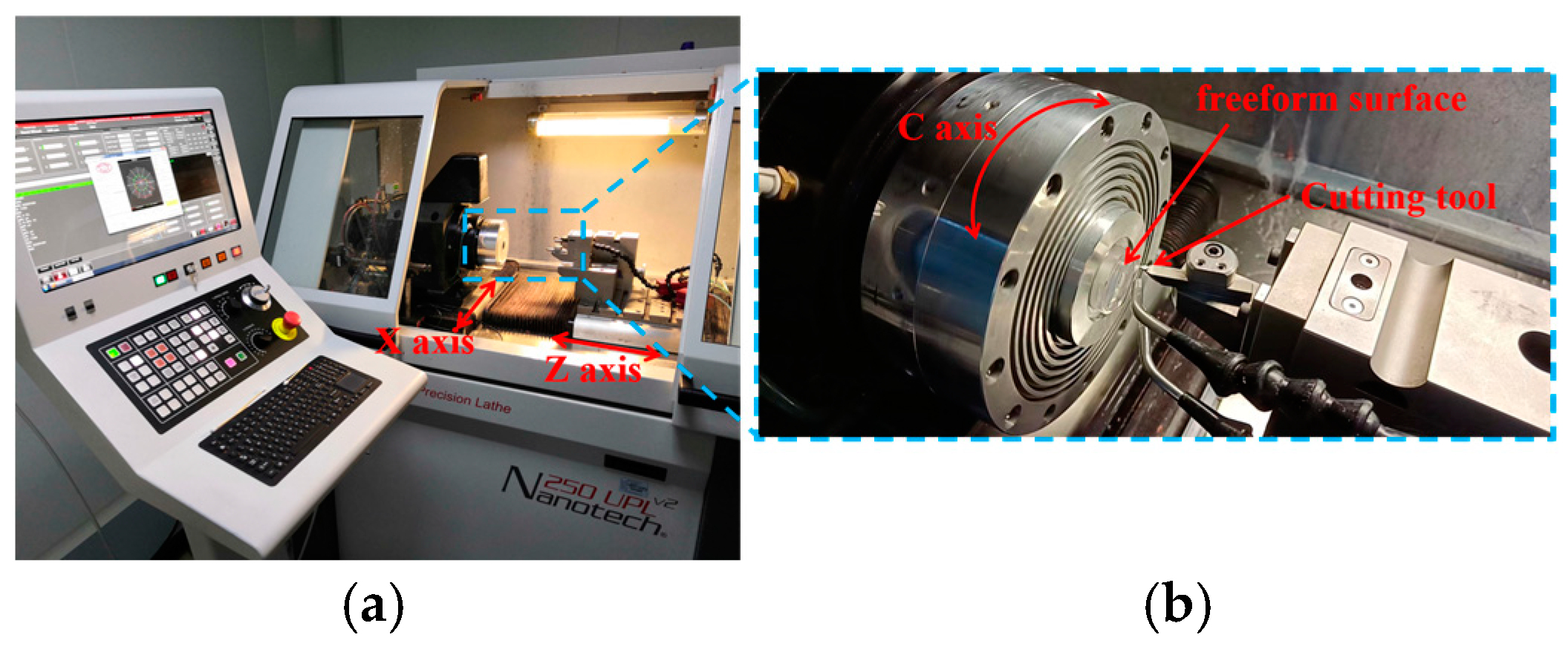
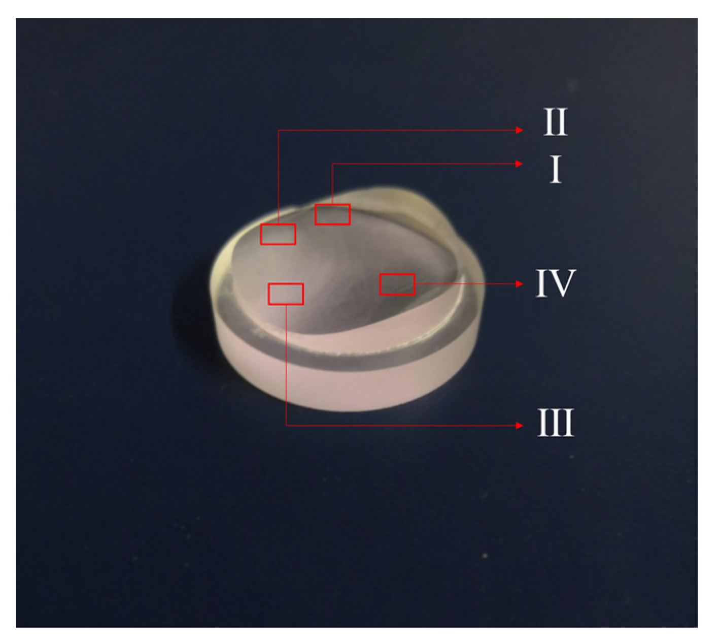
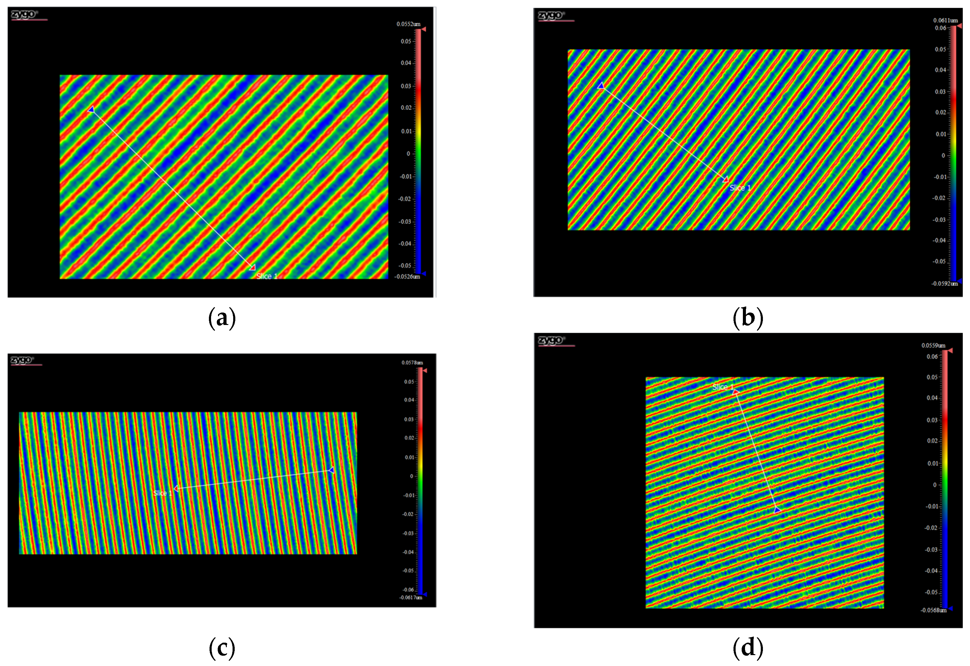
5. Experiment and Discussion

The experiment in ultra-precision slow tool servo diamond turning is conducted to confirm the validity of the proposed toolpath planning technique. The slow tool servo ultra-precision slow tool servo diamond turning machining test was performed on the Nanotech 250 UPL ultra-precision lathe, as shown in Figure 14a. The optical freeform ultra-precision turning process is shown in Figure 14b.
During the process of ultra-precision slow tool servo diamond turning with ultra-precision, the high speed of the machine spindle results in an acceleration of the X and Z axes, leading to an elevation in the servo following error. Hence, the spindle speed selected for this experiment is set at 60 rpm in order to diminish the error and obtain a well-defined freeform contour. Prior to the experiment, it is essential to scrutinize the tool parameters to prevent interference that may hamper the machining quality. The details of the machining parameters are presented in Table 1.
The processing effect of optical freeform surfaces is shown in Figure 15. Four areas (area I, area II, area III, area IV) on the optical freeform surface are selected to measure different areas of the workpiece surface and observe the residual height of the tool after ultra-precision slow tool servo diamond turning is observed. The four chosen areas cover samples of freeform surfaces with three distinct bending patterns, namely planar, concave, and convex surfaces. The tool residual heights after machining with various toolpaths are readily observable in these areas, thus lending greater credibility to this measurement method. Measurements are made using a Zygo laser interferometer on the selected surface area. The results are shown in Figure 16. Serial numbers 1 to 4 in Figure 16 correspond to the measurements in the marked area in Figure 15. The residual height information for the freeform surface obtained from the measurement results is shown in Figure 17. The serial numbers 1 to 4 in Figure 17 correspond to the residual height of the tool in the marked area in Figure 15. The experimental results show that the residual height of the entire freeform surface is stable in a small range. The experiment verifies the validity of the toolpath planning method proposed in this paper. The traditional Archimedean spiral projection method involves projecting or mapping a two-dimensional Archimedean spiral onto a three-dimensional surface to be machined. For freeform surfaces, this method does not guarantee uniform coverage of the surface [44,45].
The simulation and machining experiments are subject to some small errors due to material properties, tool wear, machining environment, and other factors. However, these errors do not affect the validity of the proposed method.

6. Conclusions

This paper proposes a toolpath planning method based on the curvature of NURBS surfaces. Through freeform surface reconstruction, the surface expression is obtained. The curvature of different positions of the surface is analyzed. Moreover, the mathematical model related to the residual height of the tool, the tool parameters, and the machining parameters are established. The machining row spacing is calculated, and the toolpath for freeform surface ultra-precision slow tool servo diamond turning is also generated directly along freeform surfaces. Compared to the machining simulation results generated by the Archimedes spiral method, the validity of the proposed machining trajectory generation method is verified. The generated toolpath is more uniform, and the residual height on the freeform surface can be maintained in a small range.

Author Contributions

Conceptualization, X.W., Q.B. and K.C.; methodology, X.W. and Q.B.; software, X.W.; validation, S.G. and L.Z.; formal analysis, Q.B. and K.C.; investigation, X.W. and Q.B.; resources, S.G., L.Z. and K.C.; data curation, X.W and L.Z.; writing—original draft preparation, X.W.; writing—review and editing, Q.B.; visualization, X.W. and S.G; supervision, Q.B. and K.C.; project administration, S.G.; funding acquisition, Q.B. and S.G. All authors have read and agreed to the published version of the manuscript.

Funding

This research was funded by the national key research and development program of China, grant number 2022YFB3402705, and the key research and development program of Heilongjiang Province, grant number 2022ZX03A05.

Data Availability Statement

All data are shown in the tables and figures in this paper.

Acknowledgments

The authors acknowledge Shandeng Chen and Yuhao Dou for their grammar check of the paper and Yan Gu for his technical support with the experiments.

Conflicts of Interest

The authors declare no conflict of interest.

References

  1. Moein, S.; Suleski, T.J. Freeform optics for variable extended depth of field imaging. Opt. Express 2021, 29, 40524–40537. [Google Scholar] [CrossRef] [PubMed]
  2. Geyl, R.; Ruch, E.; Bourgois, R.; Mercier-Ythier, R.; Leplan, H.; Riguet, F. Freeform optics design, fabrication and testing technologies for Space applications. In Proceedings of the International Conference on Space Optics—ICSO Location of Conference, Chania, Greece, 9–12 October 2018. [Google Scholar]
  3. Yang, T.; Wang, Y.; Ni, D.; Cheng, D.; Wang, Y. Design of off-axis reflective imaging systems based on freeform holographic elements. Opt. Express 2022, 30, 20117–20134. [Google Scholar] [CrossRef] [PubMed]
  4. Zheng, X.; Li, Z.; Zhang, X.; Fang, F. Manufacturing-constrained optical design methodology for cylindrical freeform reflective imaging system. Opt. Express 2018, 26, 22547–22562. [Google Scholar] [CrossRef] [PubMed]
  5. Duan, Y.; Yang, T.; Cheng, D.; Wang, Y. Design method for nonsymmetric imaging optics consisting of freeform-surface-substrate phase elements. Opt. Express 2020, 28, 1603–1620. [Google Scholar] [CrossRef] [PubMed]
  6. Ni, J.; Yang, T.; Cheng, D.; Wang, Y. Design method of wide field-of-view imaging systems using Gaussian radial basis functions freeform surfaces. Appl. Opt. 2021, 60, 4491–4501. [Google Scholar] [CrossRef]
  7. Hu, X.; Hua, H. High-resolution optical see-through multi-focal-plane head-mounted display using freeform optics. Opt. Express 2014, 22, 13896–13903. [Google Scholar] [CrossRef]
  8. Muslimov, E.; Hugot, E.; Jahn, W.; Vives, S.; Ferrari, M.; Chambion, B.; Henry, D.; Gaschet, C. Combining freeform optics and curved detectors for wide field imaging: A polynomial approach over squared aperture. Opt. Express 2017, 25, 14598–14610. [Google Scholar] [CrossRef]
  9. Yang, L.; Liu, Y.; Ding, Z.; Zhang, J.; Tao, X.; Zheng, Z.; Wu, R. Design of freeform lenses for illuminating hard-to-reach areas through a light-guiding system. Opt. Express 2020, 28, 38155–38168. [Google Scholar] [CrossRef]
  10. Shadalou, S.; Gurganus, D.; Cassarly, W.J.; Davies, M.A.; Suleski, T.J. Design, fabrication, and characterization of a tunable LED-based illuminator using refractive freeform arrays. Opt. Express 2022, 30, 42749–42761. [Google Scholar] [CrossRef]
  11. Zhu, Z.; Wei, S.; Fan, Z.; Ma, D. Freeform illumination optics design for extended LED sources through a localized surface control method. Opt. Express 2022, 30, 11524–11535. [Google Scholar] [CrossRef]
  12. Sorgato, S.; Mohedano, R.; Chaves, J.; Hernández, M.; Blen, J.; Grabovičkić, D.; Benítez, P.; Miñano, J.C.; Thienpont, H.; Duerr, F. Compact illumination optic with three freeform surfaces for improved beam control. Opt. Express 2017, 25, 29627–29641. [Google Scholar] [CrossRef] [PubMed]
  13. Yang, T.; Zhu, J.; Wu, X.; Jin, G. Direct design of freeform surfaces and freeform imaging systems with a point-by-point three-dimensional construction-iteration method. Opt. Express 2015, 23, 10233–10246. [Google Scholar] [CrossRef] [PubMed]
  14. Zhang, S.; Zhou, Y.; Zhang, H.; Xiong, Z.; To, S. Advances in ultra-precision machining of micro-structured functional surfaces and their typical applications. Int. J. Mach. Tools Manuf. 2019, 142, 16–41. [Google Scholar] [CrossRef]
  15. Zhou, X.; Zuo, C.; Liu, Q.; Lin, J. Surface generation of freeform surfaces in diamond turning by applying double-frequency elliptical vibration cutting. Int. J. Mach. Tools Manuf. 2016, 104, 45–57. [Google Scholar] [CrossRef]
  16. Zhu, Z.; Tong, Z.; To, S.; Jiang, X. Tuned diamond turning of micro-structured surfaces on brittle materials for the improvement of machining efficiency. CIRP Ann. 2019, 68, 559–562. [Google Scholar] [CrossRef]
  17. Guo, Y.; Yang, X.; Kang, J.; Zhang, W.; Wang, X.; Li, M.; Wang, Y.; Xie, Q.; Luo, S. Ductile machining of single-crystal germanium for freeform surfaces diamond turning based on a long-stroke fast tool servo. J. Manuf. Process. 2022, 82, 615–627. [Google Scholar] [CrossRef]
  18. Zhang, S.; Zong, W. A novel surface roughness model for potassium dihydrogen phosphate (KDP) crystal in oblique diamond turning. Int. J. Mech. Sci. 2020, 173, 105462. [Google Scholar] [CrossRef]
  19. Cheung, C.; Lee, W. A theoretical and experimental investigation of surface roughness formation in ultra-precision diamond turning. Int. J. Mach. Tools Manuf. 2000, 40, 979–1002. [Google Scholar] [CrossRef]
  20. Brinksmeier, E.; Gläbe, R.; Schönemann, L. Review on Diamond-Machining Processes for the Generation of Functional Surface Structures. CIRP J. Manuf. Sci. Technol. 2012, 5, 1–7. [Google Scholar] [CrossRef]
  21. Xing, Y.; Li, C.; Liu, Y.; Yang, C.; Xue, C. Fabrication of high-precision freeform surface on die steel by ultrasonic-assisted slow tool servo. Opt. Express 2021, 29, 3708–3723. [Google Scholar] [CrossRef]
  22. Balabokhin, A.; Tarbutton, J. Iso-scallop tool path building algorithm “based on tool performance metric” for generalized cutter and arbitrary milling zones in 3-axis CNC milling of free-form triangular meshed surfaces. J. Manuf. Process. 2017, 28, 565–572. [Google Scholar] [CrossRef]
  23. Takasugi, K.; Asakawa, N. Parameter-based spiral tool path generation for free-form surface machining. Precis. Eng. 2018, 52, 370–379. [Google Scholar] [CrossRef]
  24. Sato, Y.; Yan, J. Tool path generation and optimization for freeform surface diamond turning based on an independently controlled fast tool servo. Int. J. Extreme Manuf. 2022, 4, 025102. [Google Scholar] [CrossRef]
  25. Wang, D.; Sui, Y.; Yang, H.; Li, D. Adaptive Spiral Tool Path Generation for Diamond Turning of Large Aperture Freeform Optics. Materials 2019, 12, 810. [Google Scholar] [CrossRef] [PubMed]
  26. Zhang, X.; Li, Z.; Zhang, G. High performance ultra-precision turning of large-aspect-ratio rectangular freeform optics. CIRP Ann. 2018, 67, 543–546. [Google Scholar] [CrossRef]
  27. Zhang, X.; Gao, H.; Guo, Y.; Zhang, G. Machining of optical freeform prisms by rotating tools turning. CIRP Ann. Manuf. Techn. 2012, 61, 519–522. [Google Scholar] [CrossRef]
  28. Lang, C.; Li, C.; Fu, H.; Bo, S.; Yang, C.; Xue, C. Ultra-precision turning method efficient for optical freeform surfaces with a hybrid slow–fast tool servo. Appl. Opt. 2022, 61, 818–825. [Google Scholar] [CrossRef]
  29. Khaghani, A.; Cheng, K. Investigation on multi-body dynamics based approach to the toolpath generation for ultraprecision machining of freeform surfaces. Proc. Inst. Mech. Eng. Part B J. Eng. Manuf. 2019, 234, 571–583. [Google Scholar] [CrossRef]
  30. Zuo, C.; Meng, G.; Zhou, X.; Liu, Q.; Jiang, S.; Zhang, X.; Xu, P.; Zhang, Y.; Zhang, X.; Yan, G. Diamond turning of freeform surfaces using non-zero rake angle tools. Int. J. Adv. Manuf. Technol. 2021, 118, 2265–2284. [Google Scholar] [CrossRef]
  31. Zhou, M.; Zhang, H.J.; Chen, S.J. Study on Diamond Cutting of Nonrationally Symmetric Microstructured Surfaces with Fast Tool Servo. Mater. Manuf. Process. 2010, 25, 488–494. [Google Scholar] [CrossRef]
  32. Yi, A.Y.; Li, L. Design and fabrication of a microlens array by use of a slow tool servo. Opt. Lett. 2005, 30, 1707–1709. [Google Scholar] [CrossRef] [PubMed]
  33. Fang, F.Z.; Zhang, X.D.; Hu, X.T. Cylindrical coordinate machining of optical freeform surfaces. Opt. Express 2008, 16, 7323–7329. [Google Scholar] [CrossRef] [PubMed]
  34. Yin, Z.; Dai, Y.; Li, S.; Guan, C.; Tie, G. Fabrication of off-axis aspheric surfaces using a slow tool servo. Int. J. Mach. Tools Manuf. 2011, 51, 404–410. [Google Scholar] [CrossRef]
  35. Cai, H.B.; Shi, G.Q. Tool Path Generation for Multi-Degree-of-Freedom Fast Tool Servo Diamond Turning of Optical Freeform Surfaces. Exp. Tech. 2019, 43, 561–569. [Google Scholar] [CrossRef]
  36. Zhang, X.D.; Fang, F.Z.; Wang, H.B.; Wei, G.S.; Hu, X.T. Ultra-precision machining of sinusoidal surfaces using the cylindrical coordinate method. J. Micromechanics Microeng. 2009, 19, 054004. [Google Scholar] [CrossRef]
  37. Zhu, Z.; To, S. Adaptive tool servo diamond turning for enhancing machining efficiency and surface quality of freeform optics. Opt. Express 2015, 23, 20234–20248. [Google Scholar] [CrossRef]
  38. Li, Z.; Fang, F.; Chen, J.; Zhang, X. Machining approach of freeform optics on infrared materials via ultra-precision turning. Opt. Express 2017, 25, 2051–2062. [Google Scholar] [CrossRef]
  39. Liu, X.; Zhang, X.; Fang, F.; Liu, S. Identification and compensation of main machining errors on surface form accuracy in ultra-precision diamond turning. Int. J. Mach. Tools Manuf. 2016, 105, 45–57. [Google Scholar] [CrossRef]
  40. Li, Y.; Zhang, Y.; Lin, J.; Yi, A.; Zhou, X. Effects of Machining Errors on Optical Performance of Optical Aspheric Components in Ultra-Precision Diamond Turning. Micromachines 2020, 11, 331. [Google Scholar] [CrossRef]
  41. Huang, P.; Wu, X.; To, S.; Zhu, L.; Zhu, Z. Deterioration of form accuracy induced by servo dynamics errors and real-time compensation for slow tool servo diamond turning of complex-shaped optics. Int. J. Mach. Tools Manuf. 2020, 154, 103556. [Google Scholar] [CrossRef]
  42. He, C.L.; Zong, W.J.; Xue, C.X.; Sun, T. An Accurate 3d Surface Topography Model for Single-Point Diamond Turning. Int. J. Mach. Tools Manuf. 2018, 134, 42–68. [Google Scholar] [CrossRef]
  43. Piegl, L.; Tiller, W. The Nurbs Book, Monographs in Visual Communication; Springer: Berlin/Heidelberg, Germany, 1996. [Google Scholar]
  44. Han, Y.; Zhang, L.; Guo, M.; Fan, C.; Liang, F. Tool paths generation strategy for polishing of freeform surface with physically uniform coverage. Int. J. Adv. Manuf. Technol. 2017, 95, 2125–2144. [Google Scholar] [CrossRef]
  45. Qu, X.; Liu, Q.; Wang, H.; Liu, H.; Sun, H. A spiral path generation method for achieving uniform material removal depth in aspheric surface polishing. Int. J. Adv. Manuf. Technol. 2022, 119, 3247–3263. [Google Scholar] [CrossRef]
Figure 1. (a) Results of data parameterization; (b) the distribution direction of the NURBS surface.
Machines 11 01017 g001
Figure 2. Reconstructed NURBS surface.
Machines 11 01017 g002
Figure 3. Ultra-precision slow tool servo diamond turning machine model.
Machines 11 01017 g003
Figure 4. Toolpaths generated by Archimedes spiral projection.
Machines 11 01017 g004
Figure 5. A schematic diagram of the Archimedes spiral projection process.
Machines 11 01017 g005
Figure 6. Flowchart for determining the local region type of a freeform surface.
Machines 11 01017 g006
Figure 7. The area of contact between the tool and the machined surface: (a) the contact area between the tool and the machined surface; (b) the contact area between the tool and the machined surface is flat; (c) the contact area between the tool and the machined surface is convex; (d) the contact area between the tool and the machined surface is concave.
Machines 11 01017 g007
Figure 8. The tool contact point and tool arc center point.
Machines 11 01017 g008
Figure 9. Tool radius compensation and toolpath.
Machines 11 01017 g009
Figure 10. Toolpath for ultra-precision slow tool servo diamond turning after tool nose radius compensation.
Machines 11 01017 g010
Figure 11. Comparison of simulation results: (a) the toolpaths generated by Archimedes spiral projection; (b) the toolpaths generated by the toolpath planning method based on NURBS surface curvature.
Machines 11 01017 g011
Figure 12. Tool residual height of the machined surface.
Machines 11 01017 g012
Figure 13. Comparison of the simulation results of the residual height: (a) the residual height of the toolpath generated by Archimedes spiral projection; (b) the residual height of the toolpath generated by the toolpath planning method based on NURBS surface.
Machines 11 01017 g013
Figure 14. Ultra-precision slow tool servo diamond turning.
Machines 11 01017 g014
Figure 15. Machined freeform surface.
Machines 11 01017 g015
Figure 16. Measurements of the residual height in different areas of the freeform surfaces: (a) measurement results corresponding to area I in Figure 15; (b) measurement results corresponding to area II in Figure 15; (c) measurement results corresponding to area III in Figure 15; (d) measurement results corresponding to area IV in Figure 15.
Machines 11 01017 g016
Figure 17. Analysis of the residual height of different areas of the freeform surfaces: (a) the residual height corresponding to area I in Figure 15; (b) the residual height corresponding to area II in Figure 15; (c) the residual height corresponding to area III in Figure 15; (d) the residual height corresponding to area IV in Figure 15.
Machines 11 01017 g017
Table 1. Parameters of the freeform ultra-precision slow tool servo diamond turning test.
Processing ParametersNumeric Requirements
Spindle speed60 rpm
Tool arc radius1.06 mm
Tool materialDiamond
Tool rake angle
Tool back angle15°
Surface radius12.5 mm
Machining row spacing0.012 mm
Depth of cut0.01 mm
MaterialsPMMA
Disclaimer/Publisher’s Note: The statements, opinions and data contained in all publications are solely those of the individual author(s) and contributor(s) and not of MDPI and/or the editor(s). MDPI and/or the editor(s) disclaim responsibility for any injury to people or property resulting from any ideas, methods, instructions or products referred to in the content.

