Article

Strength Analysis and Structure Optimization of the Crankshaft of an Opposed-Power Reciprocating Pump

School of Mechanical Engineering, Shandong University of Technology, No. 266 Xincun West Road, Zibo 255049, China
*
Author to whom correspondence should be addressed.
Machines 2023, 11(1), 123; https://doi.org/10.3390/machines11010123
Submission received: 7 December 2022 / Revised: 6 January 2023 / Accepted: 11 January 2023 / Published: 16 January 2023
(This article belongs to the Section Electromechanical Energy Conversion Systems)

Abstract

:
The opposed-power reciprocating pump has the characteristics of high pressure, large flow, and high efficiency and energy saving. However, due to the special structure of the opposed-power reciprocating pump, existing theoretical methods cannot analyze its dynamic performance. Therefore, this paper proposes a method of analyzing the power end of the opposed-power reciprocating pump. Firstly, according to the working principle and structural characteristics of the traditional plunger pump, the novel and complex structure of the opposed-power reciprocating pump is analyzed by analogy, and the force analysis model of the crankshaft is established. The dynamic analysis model of the Matlab program is used to solve the dynamic load and section stress in the working process, and the variation law of crankshaft load is obtained. The 25 most critical working conditions are selected for analysis, and the most critical station and section of the crankshaft are obtained. With the connection between ANSYS Workbench and Solidworks, the model is imported into ANSYS Workbench, the load on the crank pin is loaded by APDL command flow, and the static analysis of the crankshaft is carried out to obtain the stress and strain of the crankshaft. Finally, the static and fatigue strength of the dangerous section is checked, and it is proven that the strength and stiffness of the crankshaft meet the design requirements. The results show that the dynamic analysis results of the crankshaft under critical working conditions are consistent with the finite element analysis, verifying the rationality of the method and providing a reference for the improvement and optimized design of the crankshaft of the opposed-power reciprocating pump.

1. Introduction

Oil-field water injection is one of the main development forms in the middle and late stages of oilfield development; it can effectively replenish formation energy and improve oil recovery and plays a positive role in ensuring stable production [1]. Karpenko M. et al. [2] proposed a research analysis of high-pressure hoses and junctions during technical maintenance. A comparative analysis of unrepaired and repaired high-pressure hoses was carried out using CFD and experimental measurements. They concluded that there were insignificant power losses in repaired hoses compared to standard hoses. Brazhenko V. [3] conducted experimental research on the change in the relative volume flow rate of plunger pump model NP-72M. The experimental results showed that changes depend largely on the purity of the fluid, where the greater the wear on the friction parts, the smaller the relative flow rate. A visual inspection of the pump parts has been carried out and the most damaged areas have been identified. At present, the main water injection equipment used is a multistage centrifugal pump, which has the advantages of large flow, small occupation area, and less maintenance work required, but the working efficiency of the unit is relatively low [4]. Especially for small capacities below 100 m3/h, the efficiency is generally approximately 70%, resulting in excessive power loss. The efficiency of the capacity of a traditional horizontal plunger pump is higher than 85%, and the power-saving space is sizeable. However, the traditional horizontal plunger pump has the characteristics of large volume and difficult maintenance. In view of the advantages and disadvantages of these two kinds of water injection pumps, a new type of water injection multi-opposed plunger pump has been developed. This novel plunger pump adopts the horizontal symmetrical arrangement of multiple cylinders. The motor and power ends adopt a double-shaft extension structure. The two ends are connected with the crankshaft and there is no empty backhaul during operation. Due to the novel and complex structure, research on this kind of pump is limited to qualitative analogy analysis, and no quantitative analysis method has been proposed.
In recent years, many scholars at home and abroad have conducted a lot of research on crankshaft strength. He L. et al. [5] found that improved one-way FSI simulation was used to calculate the dynamic stress of the runner, which takes into account fluid added for mass effect. In order to evaluate the gap influence on the added mass and dynamic stress of a pump-turbine runner, taking five different initial crank phase angles as independent variables and the minimum bending moment of the dangerous section of the crankshaft as the optimization objective, Gao J. et al. [6] used the simulated annealing algorithm to determine an optimal crank arrangement scheme. Chen L. et al. [7] established a three-dimensional model of a five-cylinder reciprocating pump crankshaft based on the characteristics of complex force and high importance. He used finite element software to analyze the flexible body dynamics of the crankshaft and determined the maximum stress position of the crankshaft. The results of the static analysis were consistent with the results of the flexible body dynamics analysis, which proved the accuracy of the scheme. Li X. et al. [8] established a three-dimensional elastoplastic contact model of hardness gradients and initial residual stress by a finite element method. The RCF characteristics of the crankshaft of an RV reducer were studied by applying Fatemi-Socie (FS). The results of the static analysis were consistent with the results of the flexible body dynamics analysis, which proved the accuracy of the scheme. Gao Y. et al. [9] solved the statically indeterminate problem of multiple supports by establishing the mathematical model of the dynamic equation of the dynamic end of the fracturing pump and using the “distribution equalized method” to obtain the key forces such as rod and supporting force, which provided a theoretical basis for the optimization design and dynamic characteristics research of the fracturing pump. Nozdrzykowski K. et al. [10] proposed a measuring system developed to support the crankshaft with a set of flexible supports. The application of these supports ensured the reaction forces and the elimination of crankshaft deformations. The experimental results showed that in order to eliminate the deformation of the crankshaft, the value of the reaction force must not only vary regarding the individual supports but also regarding the angle of rotation of the shaft during measurement.
Traditional crankshaft design mainly uses an analogy method, utilizing a theoretical formula and engineers’ own experience to determine the structure size of each part of the crankshaft and a static method to check the strength and stiffness of the crankshaft. This method involves complex calculations and its accuracy is not high. This paper takes the crankshafts of seven multi-opposed plunger pumps as an example and applies the Matlab program to establish the crankshafts’ rod force, gear force, torsional torque, and other complex alternating load dynamics model to determine the most dangerous working position of the crankshaft and the maximum section stress. Finite element software is used to analyze the stress and strain of the crankshaft and the safety factor of the crankshaft is solved according to the finite element analysis results to thereby determine the fatigue strength of the crankshaft.

2. Mathematical Model for Force Analysis of Crankshafts of Opposed-Power Reciprocating Pump

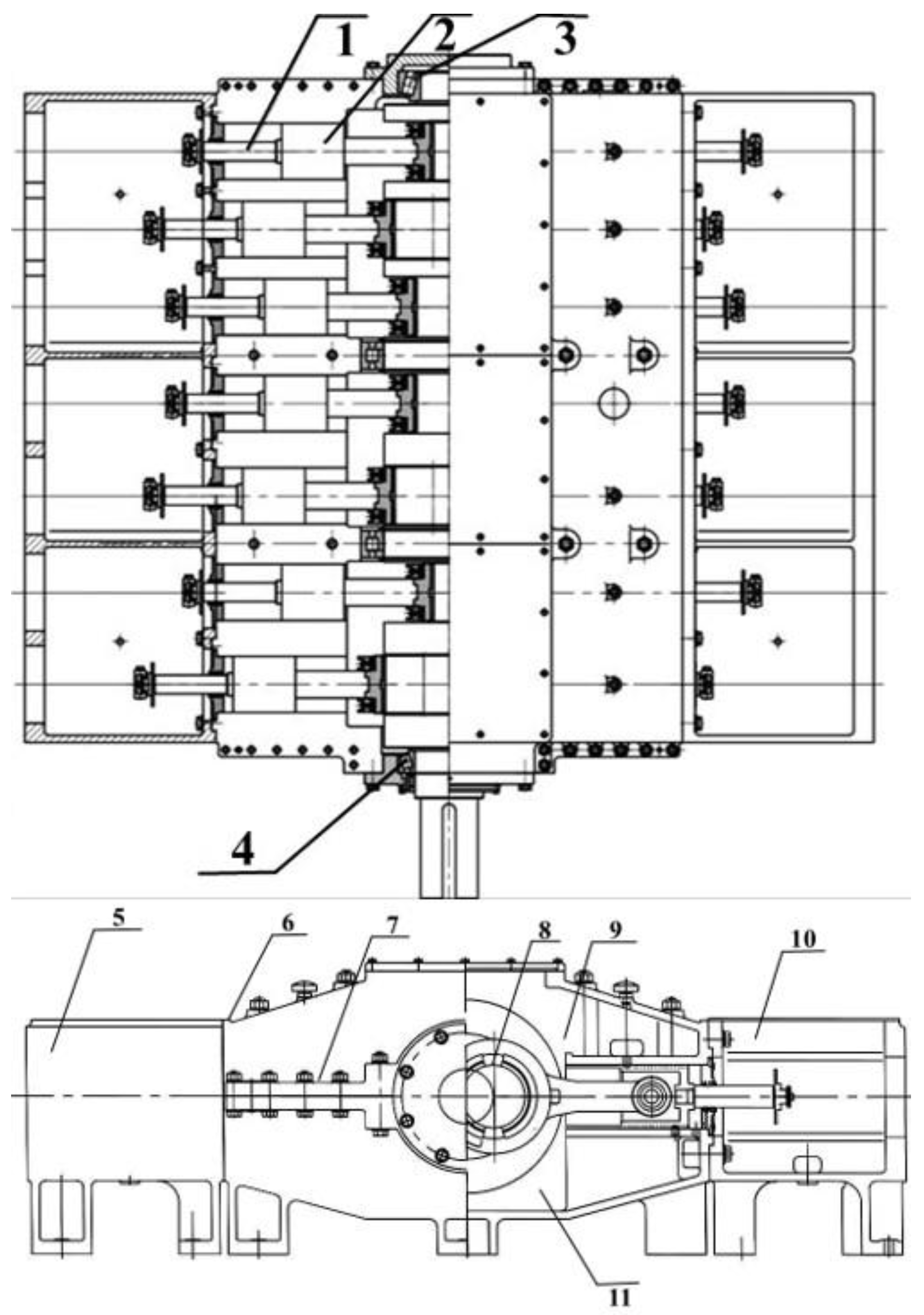
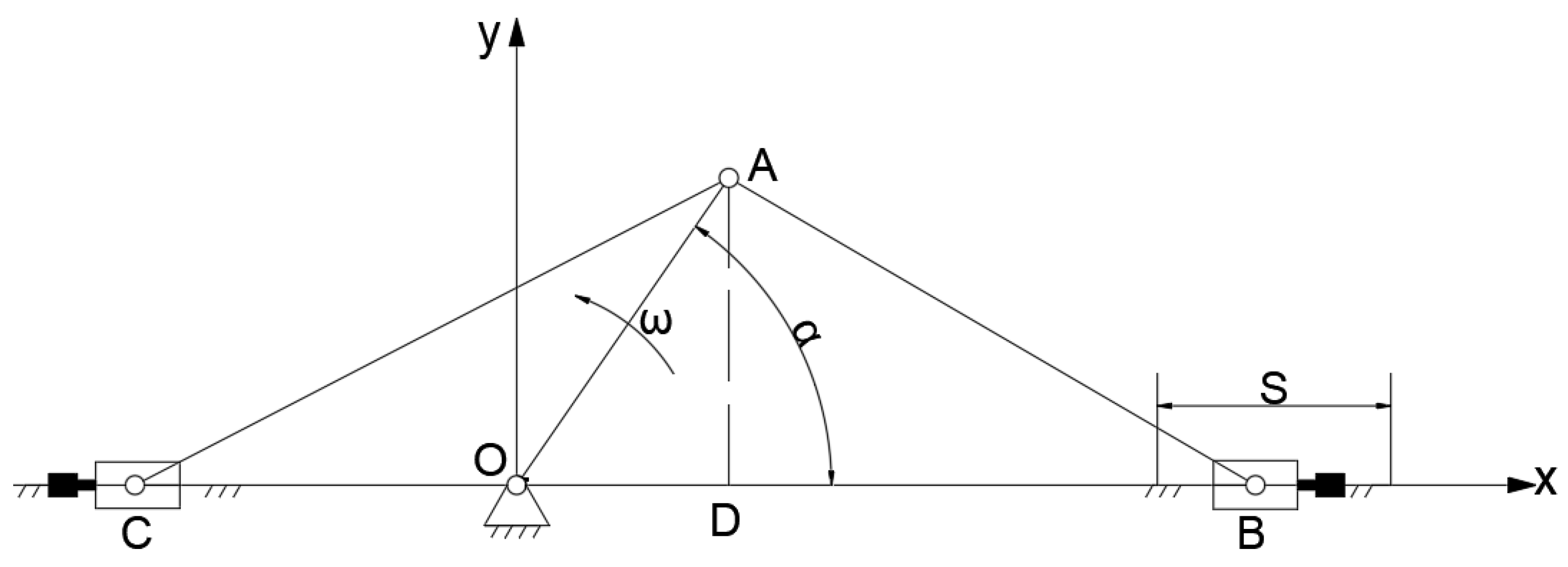
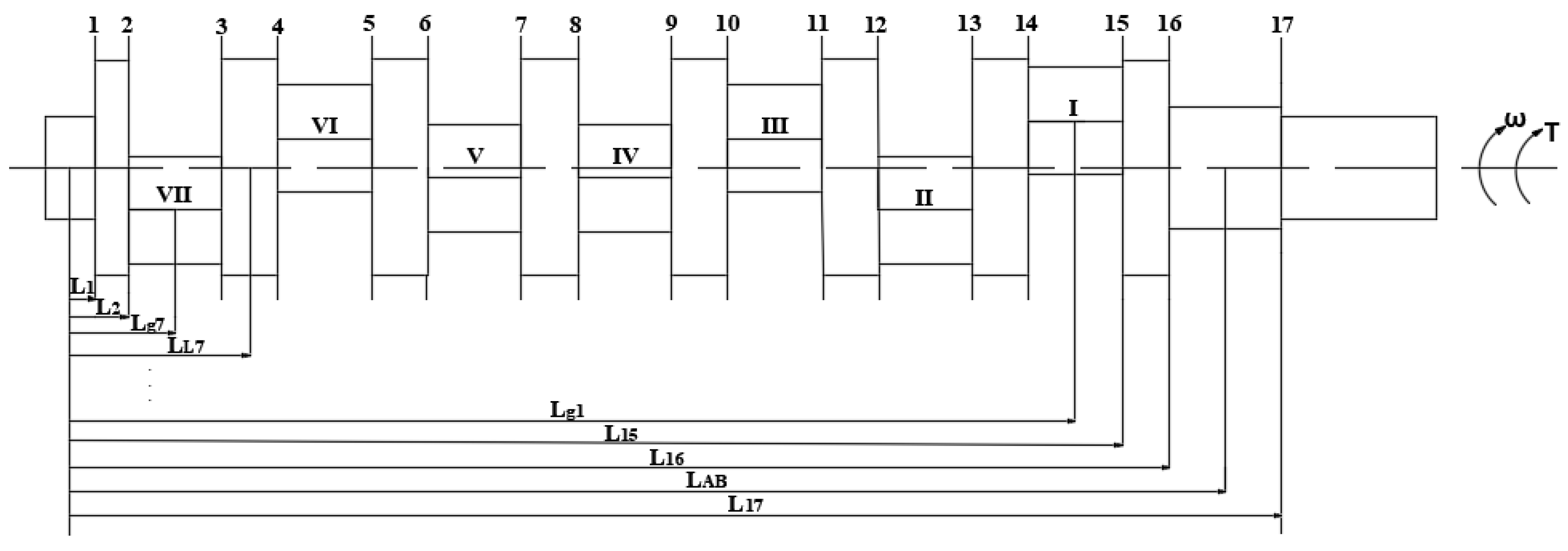
2.1. Structural Analysis and Design Parameters of Opposed-Power Reciprocating Pump

An opposed-power reciprocating pump is composed of a motor, power end, and hydraulic end of three parts. However, a special structure is made at the connection at the power end of the opposed-power reciprocating pump. Two hydraulic ends are distributed on both sides of the power end, forming an innovative structure that is different from the traditional horizontal piston pump. Figure 1 shows the structure of the opposed-power reciprocating pump. The power end part is mainly composed of a crankshaft, rod, shell, and gear reducer; the hydraulic end is mainly composed of a plunger, cylinder liner assembly, and pump head assembly [11]. Then, the three-dimensional model of the seven multiple opposed-plunger pump parts diagram can be established in SolidWorks software. The motor drives the crankshaft to rotate through the reducer, and the crankshaft rotation drives the plunger on both sides to conduct a linear reciprocating motion to realize the conversion of the energy output by the motor to the hydraulic energy of the hydraulic end on both sides. This is to complete the process of suction and discharge of the plunger pump. All the components connected to the left and right of each crankshaft crank form a structural unit called a column, and there is a fixed phase difference between the motion states of different columns. The number of plunger pumps in different models of this series is different; thus, the fixed phase difference is also different [12]. Figure 2 shows the three-dimensional model of a single column of the seven multiple opposed-plunger pump. The structure and working parameters of the seven multiple opposed-plunger pump are shown in Table 1.
The structure of a column of an opposed-power reciprocating pump can be simplified and regarded as a crank double-slider mechanism for analysis (see the motion diagram of the crank double-slider mechanism, Figure 3) [13].
Taking the crank rotation center as the coordinate origin and the crankshaft axis as the Z-axis, the xoy coordinate system is established on the middle plane of the crank. In order to analyze the crank double-slide mechanism better, the positive direction of the x axis is defined as the moving unit on the right side of the crankshaft axis, which is called the right plunger. The negative direction of the x axis is the moving unit on the left side of the crankshaft axis, which is called the left plunger. The plunger on the right side of the crankshaft axis closest to the front end of the shaft is called plunger 1, and the plunger horizontally opposed to it is called plunger 1 , and so on. The crankshaft rotation angle is α and the swing angle is β, the angular speed of the crank rotation is ω , and the displacement of the plunger is S(α) [14].
S α = R c o s α 1 + λ R 4 c o s 2 α 1
Newton’s binomial theorem is used to expand it into a series:
1 λ 2 s i n 2 α = 1 1 2 λ 2 s i n 2 α 1 8 λ 4 s i n 4 α 1 16 λ 6 s i n 6 α 1 1 2 λ 2 s i n 2 α
The plunger velocity V α is obtained by taking the derivative of Equation (1):
V α = d X d t = R ω s i n α + λ 2 s i n 2 α  
The plunger acceleration a α is obtained by taking the derivative of Equation (3):
a α = d V d t = R ω 2 c o s α + λ c o s 2 α
The crank double-slider mechanism mainly bears the piston force F P , reciprocating inertia force I w and rotational inertia force I h transmitted by the liquid cylinder, and all of them show the changing load with the corresponding function relation to the crankshaft angle. In addition, the crank double-slider mechanism also bears the reciprocating inertia force I w generated by the crosshead-plunger and connecting rod small reciprocating movement and the rotary inertia force I h generated by the crank, crank pin, and rod large unbalanced mass rotation. The crankshaft force is equivalent to the crank pin, which mainly bears tangential force T i and normal force R i [15].
F P = π D 2 P 4
I W 1 = M s R ω 2 [ c o s ( α + φ i ) + λ c o s 2 ( α + φ i ) ]
I W 2 = M s R ω 2 [ ( λ c o s 2 ( α + φ i ) c o s ( α + φ i ) ]
I h = M h R ω 2
P l = P + I W 1 + I W 2
P c l = P l c o s β i
R i = P c l c o s α i β i + I h
T i = P c l s i n α i β i
F 3 i x = T i s i n α i + R i c o s α i
F 3 i y = T i s i n α i + R i c o s α i
F H = R i 2 + T i 2
where the symbols stand for
λ rod ratio, λ = R / L ;
I w reciprocating   inertial   force ;
I h rotational   inertial   force ;
P l integrated   plunger   force ;
P c l integrated   rod   force ;
F 3 i x the   component   of   the   integrated   rod   force   along   the   x   direction ;
F 3 i y the   component   of   the   integrated   rod   force   along   the   y   direction ;
F H resultant   force ;
i number   of   each   crankshaft .

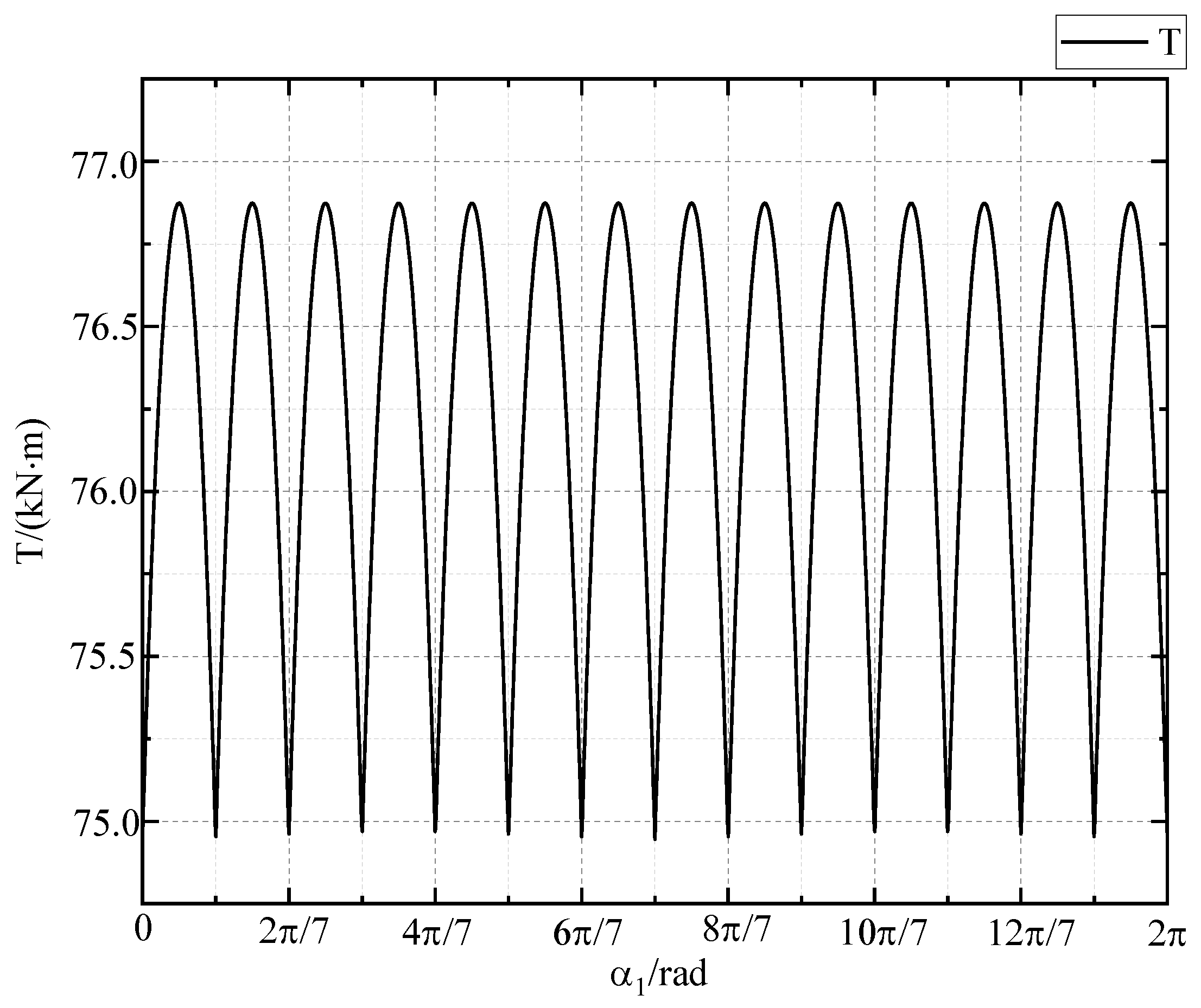
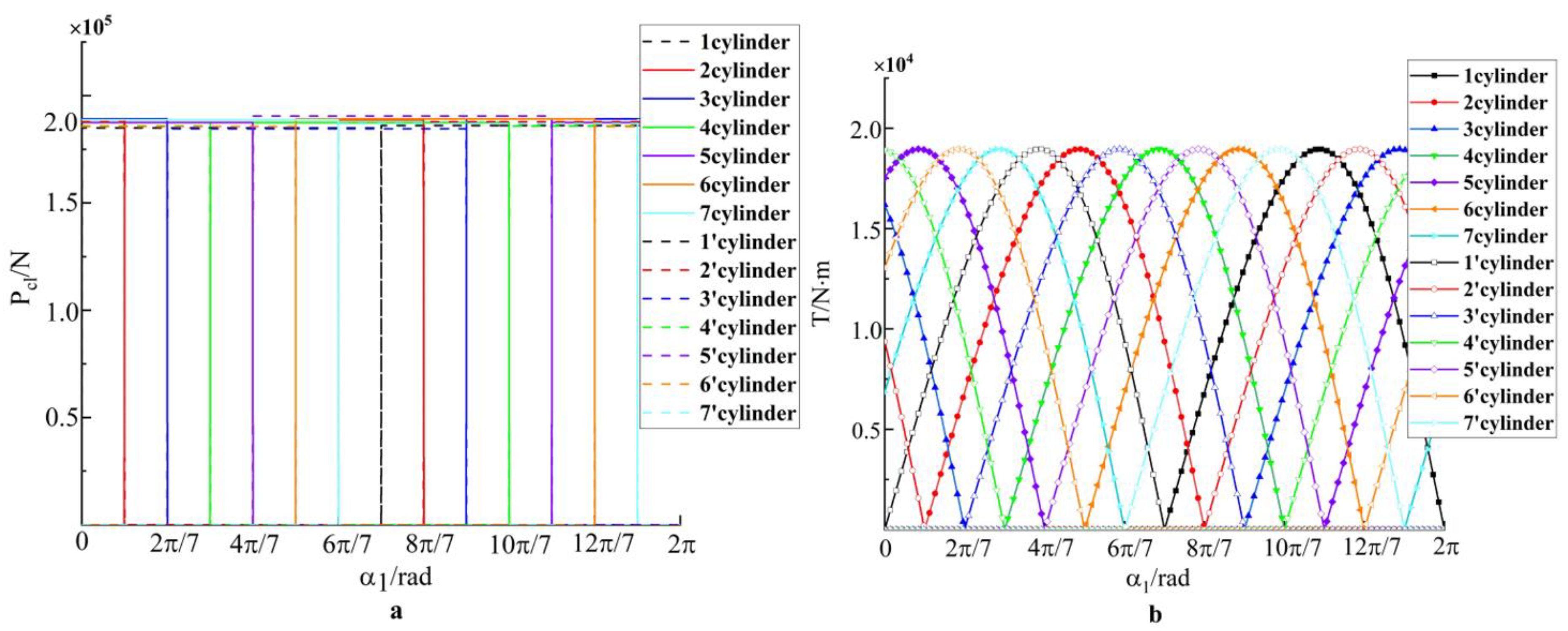
2.2. Driving Torque of Gear Mechanism

The power end of the seven multiple opposed-plunger pump mostly adopts a first-stage helical gear mechanism for deceleration. The force analysis of the helical gear assembly of the crankshaft is shown in Figure 4. The gear is subjected to tangential force F t , radial force F r , and axial force F a ; the 7 crank pins are subjected to the force of the rod; and the eight bearing seats of the box body are subjected to the action of the supporting reaction force N k x and N k y ; k = 1 , 2 , 8 is the serial number of statically indeterminate crankshaft 8 support.
The torque produced by tangential force F t of the driving gear relative to the crankshaft center is called drive torque T ; the driving torque T is equal to the sum of the balancing torque T i produced by each crank pin.
T = i = 1 7 T i R        
F t d 2 = T
F r = F t t a n α n c o s β 1
F a = F t t a n β 1
where the symbols stand for
d reference   diameter ;
α n normal   pressure   angle ;
β 1 helical   angle .
Given that the plunger is under constant pressure P, the equilibrium moment T i on each crank pin can be obtained from the force analysis of the above crank pins. The driving torque T, tangential force F t , and radial force F r can be obtained from Equations (15)–(18). Figure 5 shows the driving torque curve, Figure 6 shows the tangential force of the gear, and Figure 7 shows the radial force of the gear.
As can be observed from the above figure, the driving torque T of the crankshaft of the seven multi-opposed plunger pump is not constant but varies periodically with the crankshaft Angle α 1 , and the period is π/7. Therefore, both tangential force F t and radial force F r change periodically with the crankshaft angle. When the crank of the seven multi-opposed plunger pump rotates around, the plungers on both sides of the crankshaft alternate suction and discharge; thus, the number of liquid discharge plungers of the opposed-power reciprocating pump is constant and maximum driving torque T m a x = 76,871   N · m .

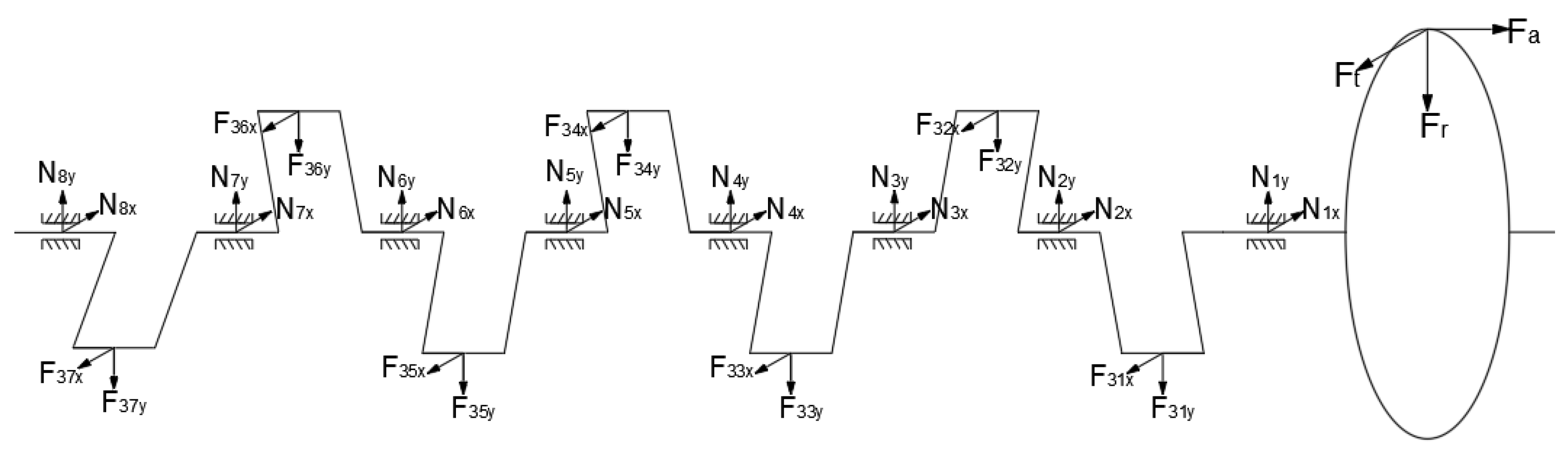
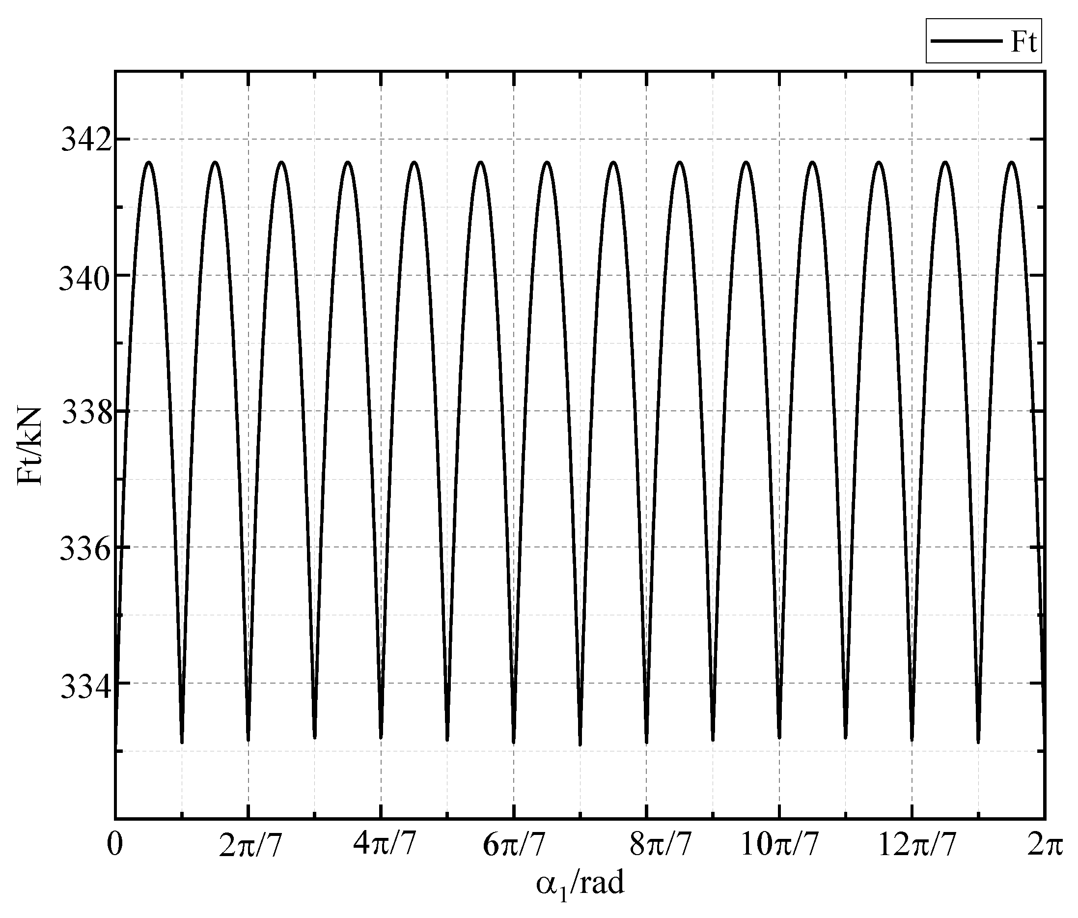
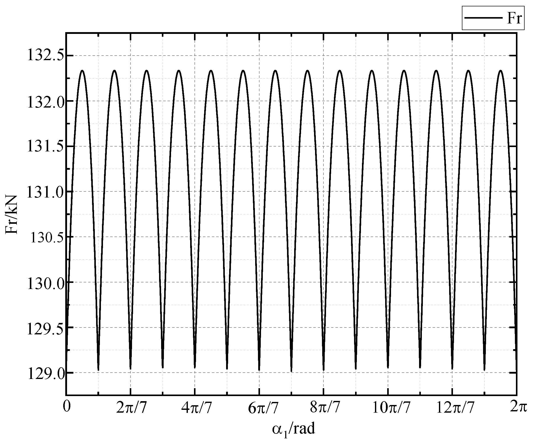
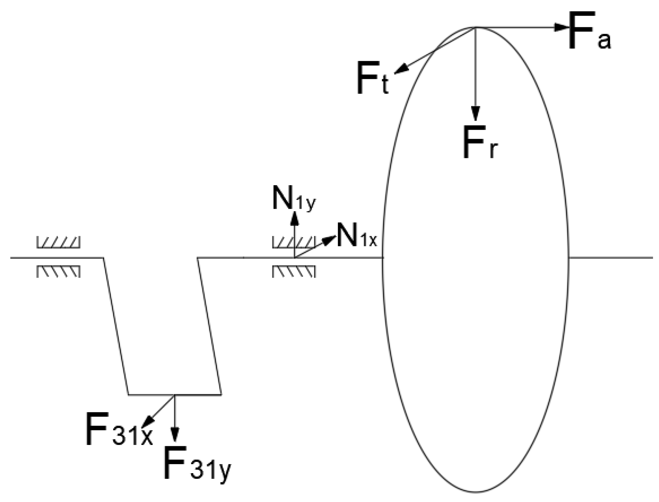
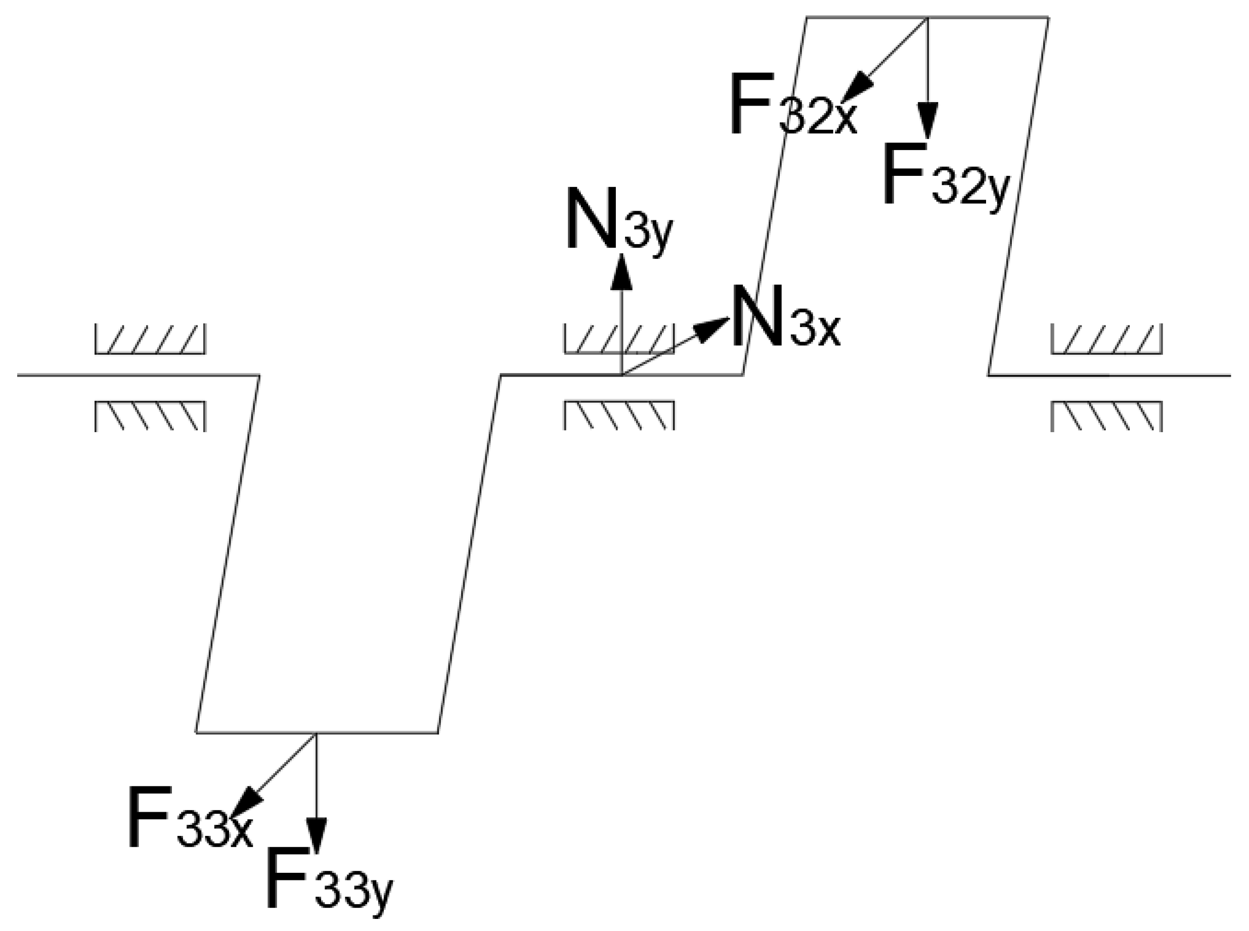
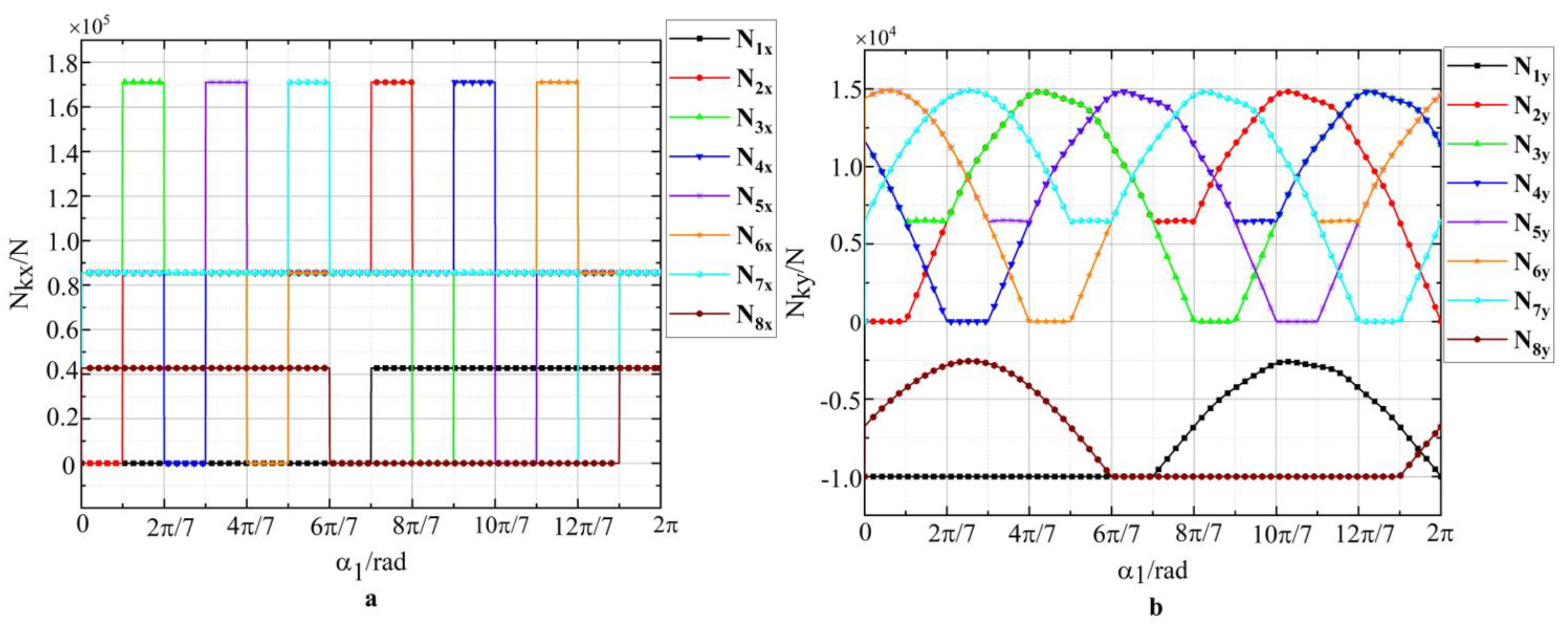
2.3. Calculation of Crankshaft Bearing Force and Section Stress

The crankshaft structure of the seven multi-opposed plunger pump comprises seven crutches and eight supports that belong to the statically indeterminate structure. In this paper, the distribution equalization method is used to solve the statically indeterminate problem in the system. In order to solve the reaction force of each crankshaft, it is assumed that the forces acting on each crank pin at the hydraulic end do not affect each other, and only the adjacent bearing supports are applied. The end gear only produces force on the adjacent box supporting the seat, and the force on the box supporting the seat is the superposition of all force vectors [8]. Therefore, the right end gear and crank double-slider mechanism corresponding to the crankshaft assembly are divided into the right end part and the middle seven parts. For each part of the right-end helical gear assembly, the simple and cantilever beams are used to solve the force N k x and N k y of the adjacent supporting seat.
The force of bearing 1 at the right end of the crankshaft is shown in Figure 8 and the bearing forces N 1 x and N 1 y at the right end can be obtained by combining the balance equation of the crankshaft.
N 1 x = 1 l A B l L 2 F t x + F r x l 18 l L 2 + F 31 x l g 1 l L 2 N 1 y = 1 l A B l L 2 F t y + F r y + m k g l 18 l L 2 + F 31 y l g 1 l L 2
The force analysis of bearing 3 in the middle of the crankshaft is shown in Figure 9, the supporting reaction force on bearings 3–6 in the middle can be obtained from Equation (21), and the supporting reaction force on bearings 2, 7, and 8 can be obtained from the balance equation of the binding force [16].
N k x = 1 2 F 3 k x 1 2 F 3 k 1 x N k y = 1 2 F 3 k y 1 2 F 3 k 1 y      
where k is the supporting number, k = 3, 4, 5, 6.
Support reaction force on supports 2, 7, and 8:
N 2 x = 1 2 F 32 x 2 3 F 31 x N 2 y = 1 2 F 32 y 2 3 F 31 y        
N 7 x = 1 L L 7 F 37 x L g 7 1 2 F 36 x N 7 y = 1 L L 7 F 37 y L g 7 1 2 F 36 y
N 8 x = 1 L L 7 F 7 x L L 7 L g 7 N 8 y = 1 L L 7 F 7 y L L 7 L g 7
where the symbols stand for
F t x the   tan gential   force   is   a   component   in   the   x   direction ;
F t y the   tan gential   force   is   a   component   in   the   y   direction ;
F r x the   radial   force   is   a   component   in   the   x   direction ;
F r y the   radial   force   is   a   component   in   the   y   direction ;
m k g gravity   at   the   gear   end .
After calculation, the component force in the x direction of the support reaction force of each supporting seat is shown in Figure 10a; the component force in the y direction of the support reaction force of each supporting seat is shown in Figure 10b.
The stress on the crankshaft is mainly the bending stress caused by the force of the rod; The crank pin and Sections 1 to 17 at the crank section mutation are selected as the critical sections, The number of the crank is I to VII, as shown in Figure 11. From the equilibrium equation, the bending moment and torque of each critical section can be obtained, taking eight critical sections as an example.
{ M x 8 = N 8 x L 8 + N 7 x L 8 L L 7 + N 6 x L 8 L L 6 + N 5 x L 8 L L 5 + F 37 x L 8 L g 7 + F 36 x L 8 L g 6 + F 35 x L 8 L g 5 M y 8 = N 8 y L 8 + N 7 y L 8 L L 7 + N 6 y L 8 L L 6 + N 5 y L 8 L L 5 + F 37 y L 8 L g 7 + F 36 y L 8 L g 6 + F 35 y L 8 L g 5 T 8 = T 7 + T 6 + T 5
Similarly, the bending moments and torques of other critical sections can be obtained.
The reaction force, rod force, and central torque are all functions of the change of crankshaft Angle [17]. The Matlab program is used to calculate the position of the first crankshaft angle of every 5° to determine the external force and section stress. The changing relationship between rod force and first crankshaft angle α 1 is shown in Figure 12a. The changing relationship between the central torque and first crankshaft angle α 1 is shown in Figure 12b.
The bending stress σ and torsional stress τ at each corner position of the 17 dangerous sections were obtained by calculation. According to the conditions of the fourth strength theory, the equivalent stress σ e q of the critical sections could be obtained.
σ e q = σ 2 + 3 τ 2  
The equivalent stresses of the critical sections 1 to 17 at different crankshaft angle positions were respectively calculated. Through comparative analysis, it can be observed that the maximum equivalent stress of the crankshaft produces the critical Section 17, which is the connection plane between the right end spindle neck and the right end of the shaft [18]. Figure 13 shows the variation of bending, torsional, and equivalent stress in Section 17. When the angle of the first crankshaft is 90°, plungers 2, 4, 5, 7, 1 , 3 , and 6 are in the draining state, and the maximum equivalent stress of Section 17 is 65.39 MPa.

3. Experimental Testing with Results

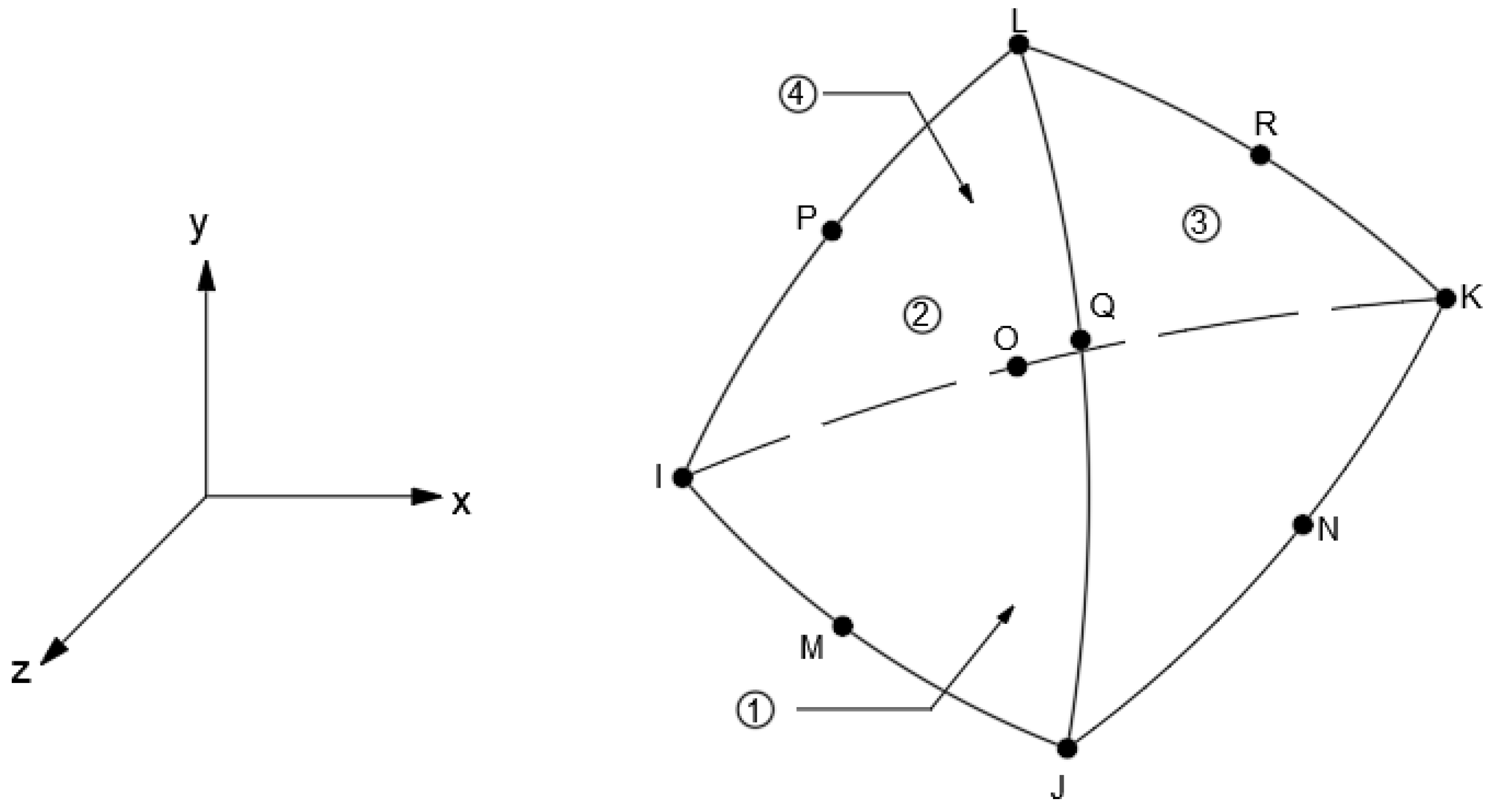
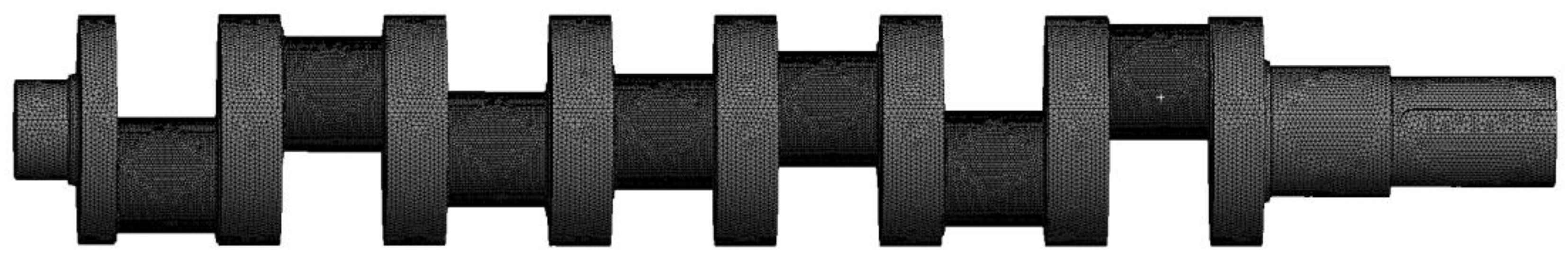
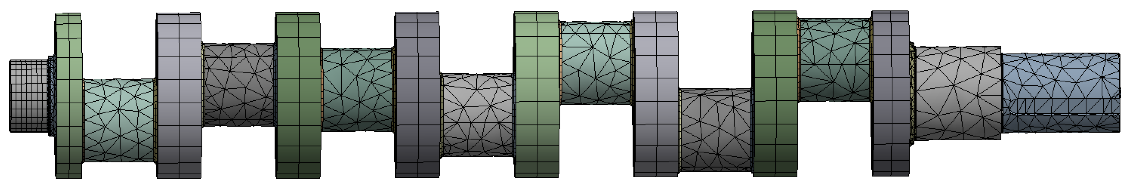
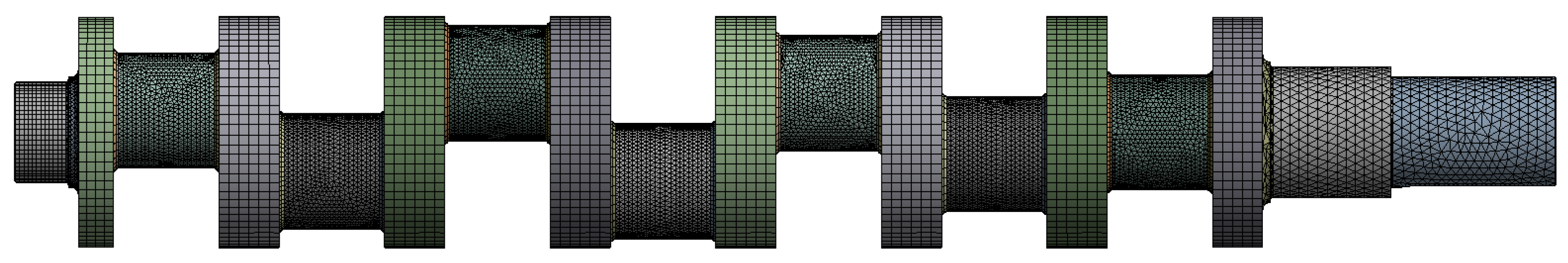
3.1. Experimental Material Setting and Grid Division

The strength analysis of the crankshaft was carried out by ANSYS finite element software. There are a variety of modeling methods. Models can be built through the modeling function of ANSYS itself or Pro-E as a solid model. In order to analyze and modify more easily and quickly, this paper uses SolidWorks software to establish a three-dimensional entity model through the interface into ANSYS for finite element analysis. This model adopts a SOLID187 tetrahedral element to divide the grid. Figure 14 shows that SOLID187 is a high-order three-dimensional 10-node solid structural unit with secondary displacement mode, which can better simulate the irregular model [19]. The unit is defined by ten nodes, each of which has three degrees of freedom for translation in the x, y, and z directions. The unit size was set to 10 mm and the mesh at the transition corners of the crankshaft was moderately encrypted. The mesh partition result of the model showed a total of 713,415 nodes and 414,623 units. Figure 15 shows the crankshaft mesh model. The crankshaft material studied in this paper is 42CrMo alloy structural steel and its properties are shown in Table 2.

3.2. Experimental Principle and Method

Assuming that the supporting rigidity of the statically indeterminate crankshaft was infinite, the crankshaft rotated only in the axial direction, thereby being an idealized model. The actual crankshaft support would deform due to stress, but the model reflected the overall stress of the crankshaft to a certain extent. Boundary conditions are usually divided into displacement boundary and force boundary conditions [20].
  • Displacement boundary constraint
Because the SOLID187 tetrahedron higher-order element must constrain the rotational degrees of freedom of all nodes in the x, y, and z directions, this paper only deals with the constraint of translational degrees of freedom. The crankshaft of the seven multiple opposed-plunger pump is a statically indeterminate structure with seven crutches and eight supports. The translation degrees of freedom in the x, y, and z directions were constrained on the circumferential surface of the right spindle neck, and the radial x and y translation degrees were constrained on the circumferential surface of the left spindle neck and the middle six points.
2.
Force boundary constraint
The load applied on the crankshaft of the seven multiple opposed-plunger pump mainly included the load on the seven crank pins, the driving torque, and the crankshaft weight.
The force distribution of the crank pin was complex and the contact between the crank pin and the bearing bush at the big head of the connecting rod was non-uniform load contact. According to the stress distribution law of the finite-width journal oil film, the force distribution law along the axis was a quadratic parabola distribution. The law of cosine distribution was in the range of 120° along the circumference of the journal [21,22]. Figure 16 shows the load distribution on the crank pin. The driving torque was applied to the right end face of the crankshaft and the dead weight was automatically added by the finite element software.
According to relevant studies, the distribution formula of connecting rod force load on the crank pin is as follows:
q x , θ = Q c 16 R L 1 x 2 L 2 c o s 3 2 θ  
where the symbols stand for
Q c total   load   on   the   crank   pin ;
R the   radius   of   the   crank   pin ;
L half   the   axial   length   of   the   crank   pin ;
θ radial   angle   of   the   surface   under   the   total   load , ( θ = π 3 π 3 );
As ANSYS does not provide the function of pressure function loading, only the slope section method can be used for an approximate solution, which is complex and has low calculation accuracy. Therefore, this paper used the APDL command flow in ANSYS Workbench to load the pressure curve function on the crank pin. The loading program was as follows:
/Soul
*afun, deg
Local,KCN,0,XC,YC,ZC,THXY ! Create local rectangular coordinate system KCN, origin XC, YC, ZC, rotation degree about Z;
csys, KCN ! Activating local coordinate system
allsell, al ! Select all objects
cmsel, s, cl ! Select the crank pin face cl
nsel, r, loc, x, -90, 90
nsel, r, loc, y, 0, 115
*set,Qc1, the resultant force on the crank pin
*set, R, 115
*set, L, 190
*get, nmax, node, 0, num, max
*get, nmin, node, 0, num, min ! Obtain the maximum and minimum node numbers
*dim, b1, array, nmax, 1, 1 ! Define array b1
*do, i, nmin, nmax ! Loop from minimum to maximum
*if, nsel(i), eq, 1, then ! The i node is the selected node
b1(i) = Qc1*(1-(nz(i)**2)/(L**2))*cos(rotz(i)*2/3)/(16*L*R/9)
*else
b1(i) = 0
*end if
*end do
sffun, pressure, bl(1) ! Take bl(1) as the loading function
sf, all, pressure, 0 ! Surface load is applied to the selected node
allsel, all ! Selecting all objects is valid
Thus, the load distribution on the crank pin could be obtained. Taking the first crank pin as an example, Figure 17 shows the variation of the total load in a simulated period.
It can be observed from Figure 16 that with the increase of crankshaft angle α 1 , the seven multi-opposed plunger pump was installed. The total load Q c on the crank pin increased and decreased continuously. When the crankshaft angle α 1 was π / 2 and 3 π / 2 , the total load on the crank pin reached its peak. This was because the cranks of the seven multi-opposed plunger pump rotated around and the plungers on both sides of the crankshaft alternated suction and discharge in a cycle. When the plunger drained, the load on the crank pin reached a peak; thus, there were two peaks in a cycle, and the load curves on different crank pins had a fixed phase difference. Therefore, the load boundary conditions at any point on the crankshaft could be determined under any working condition, the load on the crank pin could be loaded by APDL command flow, and the statics of the crankshaft could be analyzed by Workbench [23].

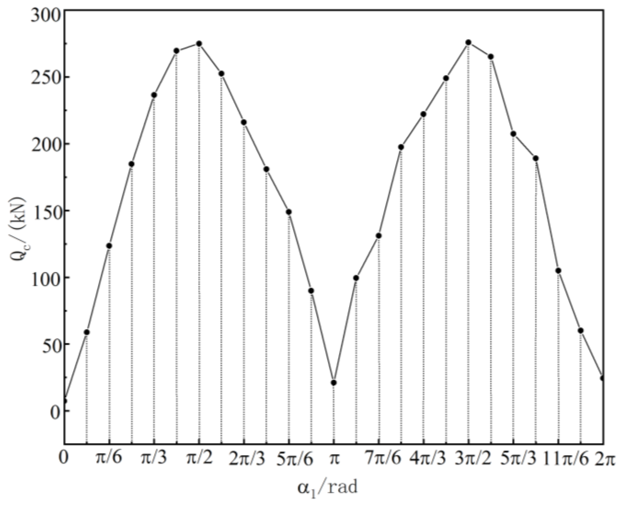
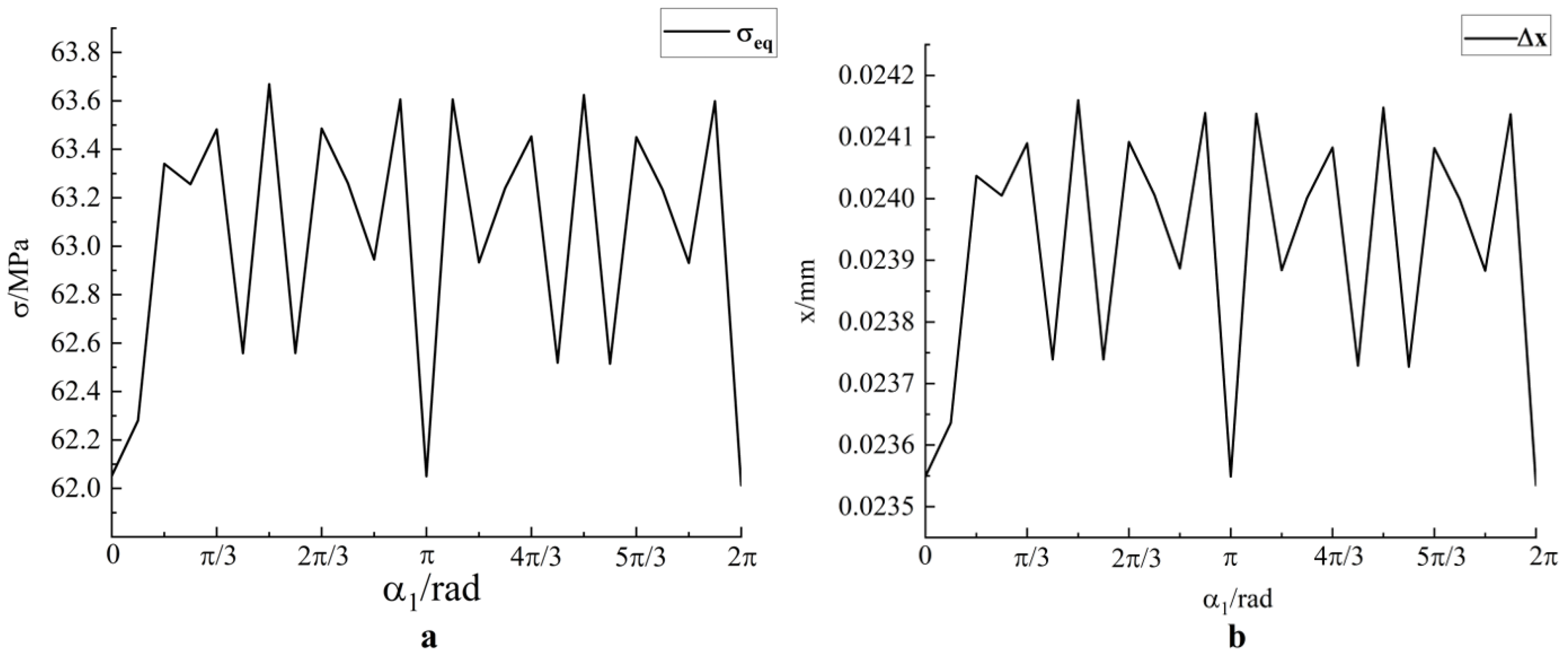
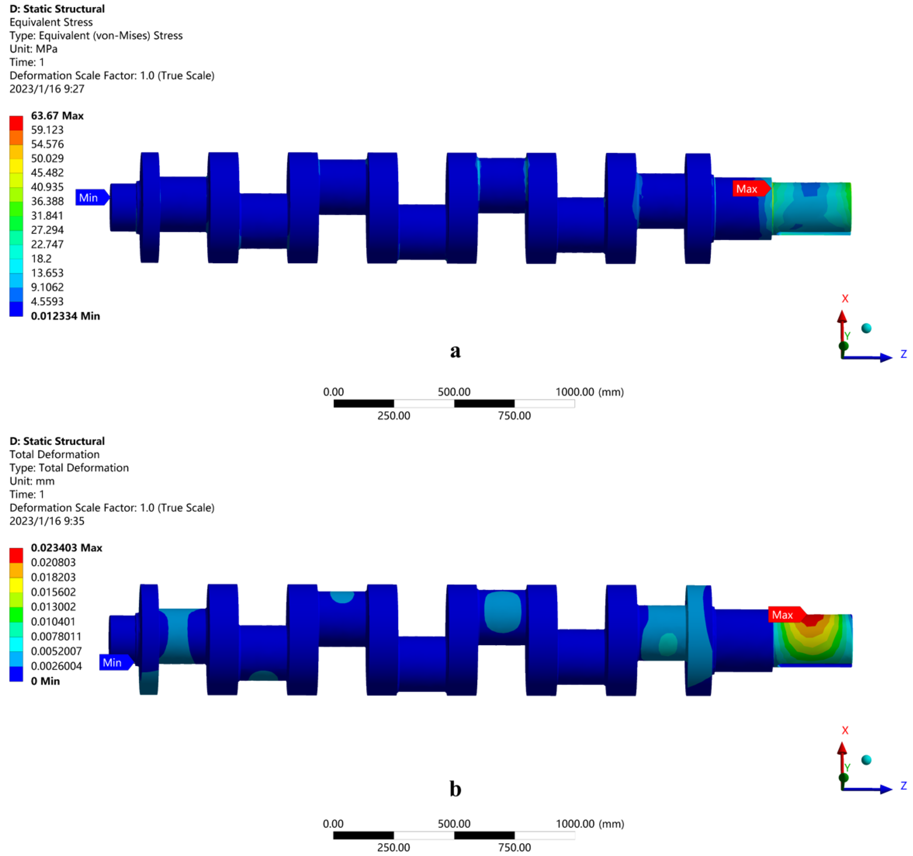
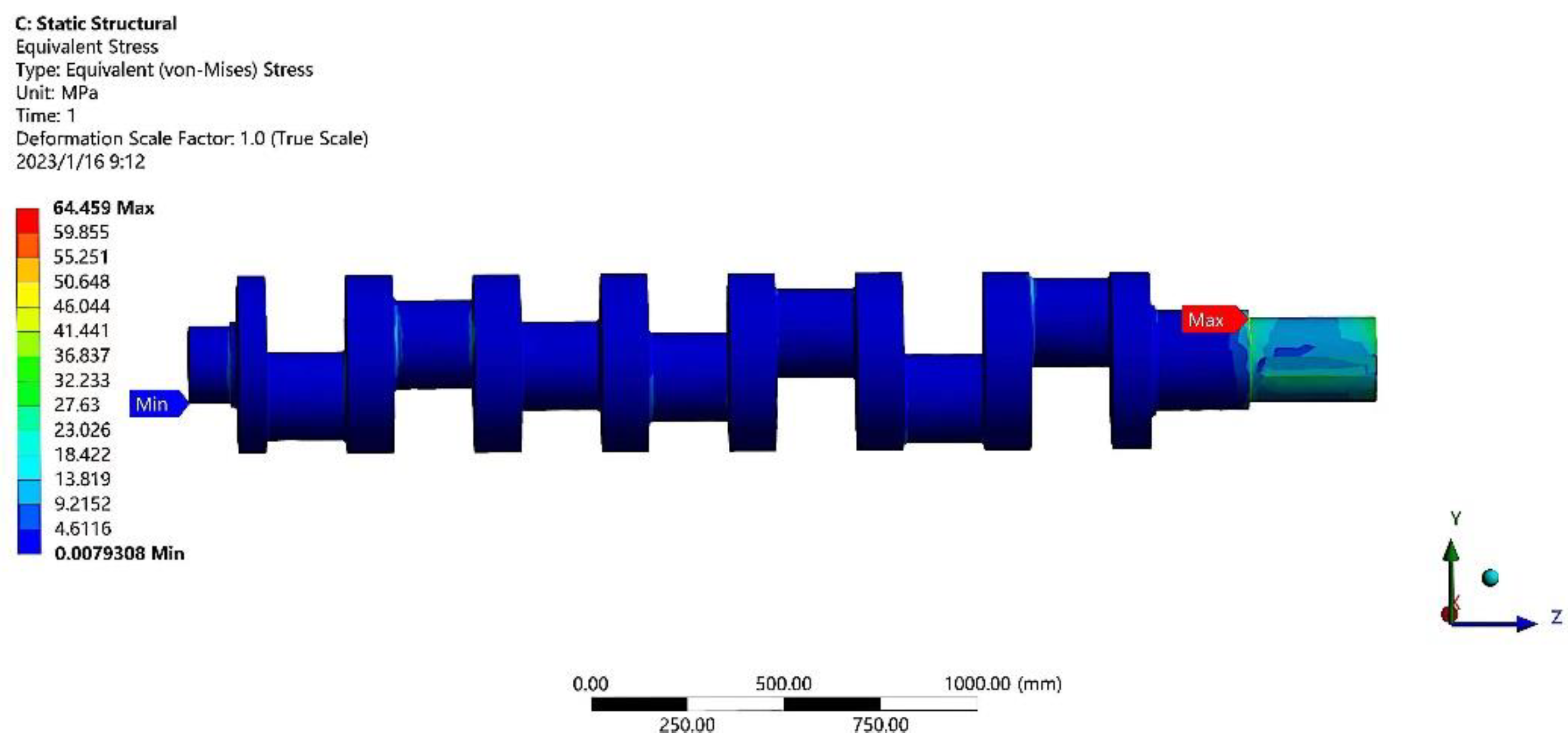
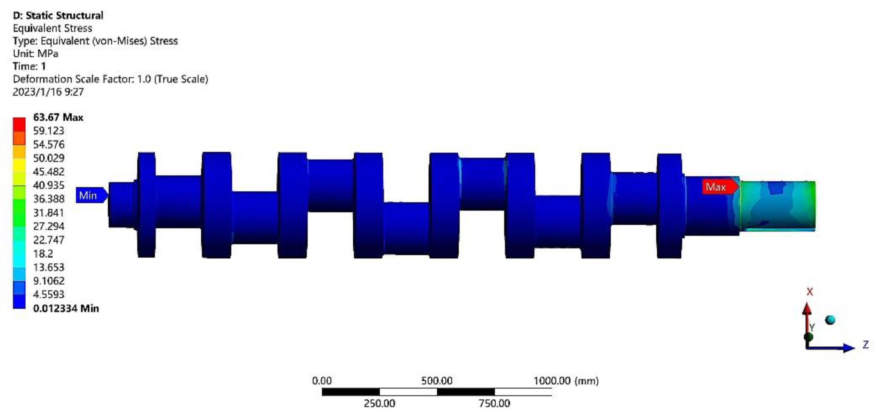
3.3. Experimental Results and Analysis

The crankshaft boundary conditions and loads were added as described above. Starting from the crankshaft angle of 0°, each 15° was a working condition, and 25 working conditions within a cycle were simulated. Figure 18a shows the changes in the maximum equivalent stress of the crankshaft under 25 working conditions; Figure 18b shows the maximum shape variable of the crankshaft under 25 working conditions [24]. The maximum equivalent stress of the crankshaft under 25 working conditions occurred in the connection plane between the right spindle neck and the right end of the shaft (critical Section 17), which was consistent with the theoretical calculation results of the dangerous section. Through dynamic and finite element analyses, it was proven that the maximum equivalent stress was 63.67 MPa when the rotation angle of the first crankshaft was 90°, which occurred in Section 17. Figure 19a shows the maximum equivalent stress distribution cloud diagram of the crankshaft under 25 working conditions when the crankshaft angle was 90°; Figure 19b shows the maximum deformation distribution cloud of the crankshaft under 25 working conditions when the crankshaft angle was 90°.

3.4. Grid Independence Verification

Finite element meshing is very important in numerical simulation analysis, which directly affects the accuracy of subsequent numerical calculation results. Therefore, it was necessary to conduct independent grid experiments on the crankshaft. Figure 20 shows the automatic meshing model of the crankshaft. The maximum equivalent stress on the crankshaft was generated at the step fillet at the end of the keyway and the maximum equivalent stress was 64.459 MPa. Figure 21 shows the maximum equivalent stress under automatic meshing.
After that, hexahedral subdivision was performed on some components of the model and the mesh size was reduced for the main stressed parts. Figure 22 shows the refined crankshaft meshing model. Using the same analytical settings as the default meshing partition, Figure 23 shows the maximum equivalent stress under mesh refinement.
According to the above analysis, the maximum equivalent stress on the model obtained after changing the mesh division mode and refining the mesh was 63.67 Mpa and the maximum stress point was still located at the step fillet at the end of the keyway. The difference from the maximum stress of default meshing was no more than 1 MPa and the relative difference was approximately 1%. Due to the large changes in the meshing part of the two calculations, this calculation difference could be counted as the internal grid calculation error of the model. Compared with the maximum equivalent stress result, this error was relatively small, and the initial calculation result was still of high reference value. Therefore, it can be observed that the calculation result was not related to the model meshing.

4. Crankshaft Strength Check

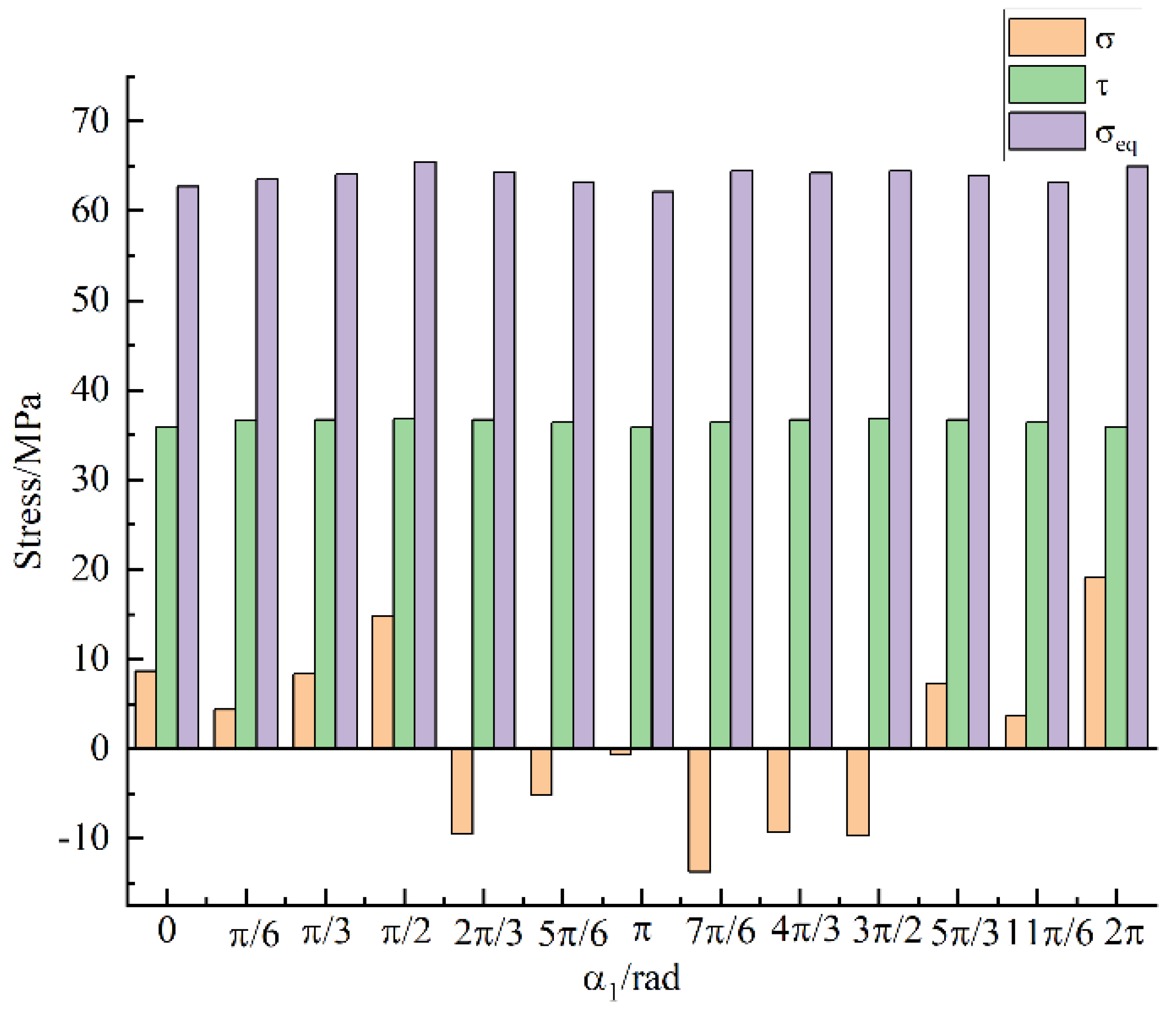
4.1. Static Strength Check of the Crankshaft

The crankshaft of the seven multiple opposed-plunger pump was made of 42 CrMo alloy steel, which mainly fails in the form of yield. The safety factor is calculated by the static strength formula [25]:
n = σ b σ m a x n  
where [n] is allowable safety and 1.6 ~ 3 , [n] = 3; σ m a x is generally the maximum   stress   value .
The static strength of the statically indeterminate crankshaft is calculated according to Equation (28),   n = 17.8 > n . Therefore, the static strength of the statically indeterminate crankshaft of the seven pairs piston pump met the design requirements.

4.2. Check the Fatigue Strength of the Crankshaft

The fatigue strength of critical Section 17 of the crankshaft was determined. According to the above, the failure forms of the crankshaft are mainly bending fatigue and torsional fatigue failure. Respectively for the crankshaft bending fatigue strength check, torsion fatigue strength check, and bending torsion under the combined action of the check, the formulas of safety factor S σ , S τ , and S are respectively as follows [26]:
S σ   = σ 1 k σ β 2 ε σ σ a + ψ σ σ m
S τ = τ 1 k τ β ε τ τ a + ψ τ τ m
S = S σ S τ S σ 2 + S τ 2
where the symbols stand for
σ 1 bending   fatigue   ultimate   strength ;
τ 1 torsional   fatigue   ultimate   strength ;
σ a amplitude   of   bending   stress ;
τ a amplitude   of   torsional   stress ;
σ m average   bending   stress ;
τ m average   torsional   stress ;
ψ σ coefficient   of   bending   equivalence ;
ψ τ coefficient   of   torsional   equivalence ;
ε σ , ε τ absolute   dimensional   factor ;
β 2 superficial   mass   factor ;
K σ bending   stress   concentration   factor ;
K τ torsional   stress   concentration   factor .
σ a , σ m , τ a , and τ m can be obtained through Equations (32)–(35):
σ a = σ m a x σ m i n 2
σ m = σ m a x + σ m i n 2
τ a = τ m a x τ m i n 2
τ m = τ m a x + τ m i n 2
The maximum and minimum stress can be obtained by finite element and crankshaft stress analyses. The coefficients of Equations (29) and (30) can be obtained from reference [25], as shown in Table 3.
According to the calculation, the bending fatigue coefficient of the crankshaft was 2.546, the torsional fatigue coefficient was 4.267, and the safety coefficient under the combined action of bending and torsion was 2.186. For the seven multiple opposed-plunger pump crankshaft, the material properties of uniform, and accurate load shaft class, the allowable safety factor S p is 1.5; therefore, S > S p , meet the design requirements for a multi-pair large flow high-pressure plunger pump.

5. Conclusions

Through the stress analysis of the crankshaft, the stress of each crank pin was obtained. By calculating the internal forces of each section, the critical section was found, and the theoretical strength of the critical section was analyzed. The maximum equivalent stress of the crankshaft under 25 working conditions was obtained by finite element analysis software. Finally, the strength of the critical section of the crankshaft that produced the maximum stress was determined, and the following analysis conclusions are drawn:
(1) Through the analysis of the dynamic load and section stress of the crankshaft, it is found that the supporting reaction force, rod force, and central torque are functions of the change of the crankshaft angle, thereby determining the most critical station and section of the crankshaft. When crankshaft Angle 1 is 90°, the maximum equivalent stress is 65.39 MPa, which is generated in Section 17. That is the connection plane between the right spindle neck and the right end of the shaft.
(2) The finite element analysis method was used to impose constraint conditions on the crankshaft. The finite element analysis results are consistent with the theoretical analysis results, that is, when the crankshaft rotation Angle is 90°, the maximum equivalent stress is generated in Section 17. According to the finite element method, the maximum equivalent stress is 63.67 MPa, which is consistent with the theoretical analysis result, thereby verifying the accuracy of the finite element analysis.
(3) Independent grid experiments were carried out, verifying that the calculation results of the maximum equivalent stress of the crankshaft were independent of grid division and the accuracy of finite element analysis.
(4) The calculated safety factor S of the crankshaft fatigue strength was 2.186, which was greater than the allowable safety factor S. This implies safe operating conditions and meets the design requirements of the statically indeterminate crankshaft of the seven multiple opposed-plunger pump.
This design method for a crankshaft can accurately determine the most dangerous working position and section of the crankshaft and judge whether the crankshaft meets design requirements. Future work will focus on developing a computer programming system to solve the dynamic load and determine the strength of the dangerous section.

Author Contributions

Conceptualization, C.L. and X.W.; methodology, C.L. and X.W.; software, Z.Y. and Z.L.; validation, Z.Y., Z.L. and Z.M.; data curation, C.L.; writing—original draft preparation, C.L.; writing—review and editing, C.Z.; supervision, X.W.; project administration, X.W.; funding acquisition, X.W. All authors have read and agreed to the published version of the manuscript.

Funding

This research received no external funding.

Institutional Review Board Statement

The study did not require ethical approval.

Informed Consent Statement

Informed consent was obtained from all subjects involved in the study.

Data Availability Statement

Not applicable.

Conflicts of Interest

We have no competing financial interests or personal relationships that could have appeared to influence the work reported in this paper.

References

  1. Zhu, H.; Yan, H.; Ni, B.; Lu, X. Development and application of opposite type large displacement reciprocation water injection pump. China Pet. Chem. Stand. Qual. 2020, 40, 122–128. [Google Scholar]
  2. Karpenko, M.; Prentkovskis, O.; Sukevicius, S. Research on high-pressure hose with repairing fitting and influence on energy parameter of hydraulic drive. Eksploat. I Niezawodn.-Maint. Reliab. 2022, 24, 25–32. [Google Scholar] [CrossRef]
  3. Brazhenko, V. The influence of contaminated hydraulic fluid on the relative volume flow rate and the wear of rubbing parts of the aviation plunger pump. Aviation 2019, 23, 43–47. [Google Scholar] [CrossRef] [Green Version]
  4. Yan, L.; Liu, C.; Xing, F.; Jiang, W.; Zhang, F. Improved application of plunger injection pump technology. Mech. Eng. 2021, 7, 109–113. [Google Scholar]
  5. He, L.; Zhou, L.; An, X.; Wang, Z.; Nakahara, Y.; Kurosawa, S. Evaluation of gap influence on the dynamic response behavior of pump-turbine runner. Eng. Comput. 2019, 36, 491–508. [Google Scholar] [CrossRef]
  6. Gao, J.; Yao, C.; Liu, Q.; Liu, T.; Jiao, H. Simulated annealing algorithm-based optimization of crank phase arrangement of quintuple-cylinder reciprocating pump. J. Drain. Irrig. Mach. Eng. 2020, 38, 878–884. [Google Scholar]
  7. Chen, L.; Fu, Y.; Chen, H.; Guan, R.; Xu, X. Flexible body dynamics of five-cylinder reciprocating pump crankshaft. J. Drain. Irrig. Mach. Eng. 2020, 38, 770–774. [Google Scholar]
  8. Li, X.; Shao, W.; Tang, J.; Ding, H.; Zhou, W. An Investigation of the Contact Fatigue Characteristics of an RV Reducer Crankshaft, Considering the Hardness Gradients and Initial Residual Stress. Materials 2022, 15, 7850. [Google Scholar] [CrossRef]
  9. Gao, Y.; Hu, Y.; Dong, H.; Dan, D. The dynamic study on quintuple cylinders fracturing pump power end. Mach. Des. Manuf. Eng. 2018, 47, 23–26. [Google Scholar]
  10. Nozdrzykowski, K.; Grządziel, Z.; Grzejda, R.; Warzecha, M.; Stępień, M. An Analysis of Reaction Forces in Crankshaft Support Systems. Lubricants 2022, 10, 151. [Google Scholar] [CrossRef]
  11. Dai, J.; Zhao, Y.; Wang, Z.; Cai, T. Dynamic Characteristics Analysis on crankshaft of high pressure emulsion pump based on SolidWorks and ANSYS. Mach. Tool Hydraul. 2015, 43, 152–156. [Google Scholar]
  12. Zhong, X.; Wei, X.; Wang, Z.; Zhu, C. Kinematic Analysis of Multiple Opposed-Plunger Pump Based on MATLAB. Mach. Des. Manuf. 2017, 9, 216–224. [Google Scholar]
  13. Liu, Y.; Wei, X. Analysis of disturbing force of double-acting reciprocating pump. J. Shandong Univ. Technol. 2015, 29, 43–45. [Google Scholar]
  14. Wei, J.; Feng, J.; Zhang, M.; Ma, L. Optimization of crank epoch angle arrangement of quintuple pump based on strength theory of crankshaft. J. Drain. Irrig. Mach. Eng. 2018, 36, 294–299. [Google Scholar]
  15. Li, W.; Hong, L. Numerical Analysis of Dynamics of Power End of Five-cylinder reciprocating Fracturing Pump. J. Mech. Transm. 2016, 40, 138–142. [Google Scholar]
  16. Design of Reciprocating Pump Writing Group. Reciprocating Pump Design; China Machine Press: Beijing, China, 1987. [Google Scholar]
  17. Ji, Y.; Zhu, Z.; Zhang, Z.; Sun, G.; Yin, M. Strength analysis of high-power drilling pump crankshaft with double side helical gear drive. Mech. Sci. Technol. Aerosp. Eng. 2017, 36, 1856–1858. [Google Scholar]
  18. Li, R.; Wang, W.; Su, Z. Fatigue Strength Analysis of Bent Axle of Large-flow and High-pressure Emulsion Pump. Coal Min. Technol. 2014, 19, 45–48. [Google Scholar]
  19. Ning, C.; Fang, Z.; Wang, F.; Wang, X. Several entity element in the comparison of aviation gear box calculation. J. Mech. Strength 2015, 37, 742–747. [Google Scholar]
  20. Li, W. Design and Analysis of the Power End of the High-Power Fracturing Pump; Dalian University of Technology: Dalian, China, 2014. [Google Scholar]
  21. Li, Y.; Xue, H. Analysis on fatigue strength of crankshaft in mine-used flame proof diesel engine based on sub-model. Min. Process. Equip. 2014, 42, 131–134. [Google Scholar]
  22. Liu, D.; Li, W.; Zhang, R.; Yang, J.; Shi, W. Finite element analysis for crankshaft strength of a vehicle diesel engine based on ANSYS Workbench. Automob. Parts 2017, 10, 20–24. [Google Scholar]
  23. Xu, Z. Fatigue Strength Analysis and Dynamic Load Test of Reciprocating Pump Crankshaft; Shanghai Jiao Tong University: Shanghai, China, 2011. [Google Scholar]
  24. Huang, Y.; Deng, D.; Liu, Y.; Zhang, Z.; He, M.; Li, H. Finite element analysis of 16V170 diesel engine crankshaft based on Pro/E and ANSYS. Agric. Equip. Veh. Eng. 2012, 2, 47–50. [Google Scholar]
  25. Li, M.; Zhou, S.; Li, N.; Xing, T. Load Calculation and Fatigue Life Analysis of Crankshaft of Quintuple Cylinders Fracturing Pump. Oil Field Equip. 2009, 38, 41–44. [Google Scholar]
  26. Mechanical Design Manual Editorial Board. Mechanical Design Manual (3rd): Mechanical Components and Transmission Design, 3rd ed.; China Machine Press: Beijing, China, 2004. [Google Scholar]
Figure 1. Opposed-power reciprocating pump mechanism structure: 1. Extension rod, 2. Crosshead, 3. Rear bearing, 4. Fore bearing, 5. Left join segment, 6. Box, 7. Rod, 8. Crankshaft, 9. Upper box, 10. Right join segment, 11. Lower box.
Machines 11 00123 g001
Figure 2. Opposed-power reciprocating pump in a separate column: 1. Plunger, 2. Manger, 3. Extension rod, 4. Crosshead, 5. Rod, 6. Crankshaft.
Machines 11 00123 g002
Figure 3. Schematic diagram of the motion and force of the Crank double-slider mechanism.
Machines 11 00123 g003
Figure 4. Force analysis of the crankshaft.
Machines 11 00123 g004
Figure 5. Diagram of the crankshaft driving torque.
Machines 11 00123 g005
Figure 6. Diagram of the tangential force of the gear.
Machines 11 00123 g006
Figure 7. Diagram of the radial force of the gear.
Machines 11 00123 g007
Figure 8. Diagram of force analysis on support 1 of the crankshaft.
Machines 11 00123 g008
Figure 9. Diagram of force analysis on middle support 3 of the crankshaft.
Machines 11 00123 g009
Figure 10. (a) Diagram of the x-direction support reaction force Nkx of each support seat of the crankshaft, (b) Diagram of the y-direction support reaction force Nky of each support seat of the crankshaft.
Machines 11 00123 g010
Figure 11. Crankshaft critical sections.
Machines 11 00123 g011
Figure 12. (a) Diagram of the rod force changing with the first angle, (b) Diagram of the torque changing with the first angle.
Machines 11 00123 g012
Figure 13. Diagram of stress variation in Section 17.
Machines 11 00123 g013
Figure 14. SOLID187 unit figure.
Machines 11 00123 g014
Figure 15. Crankshaft grid mode.
Machines 11 00123 g015
Figure 16. Diagram of load distribution on the crank pin.
Machines 11 00123 g016
Figure 17. Schematic diagram of the load on the crank pin and the change curve of the first crankshaft angle.
Machines 11 00123 g017
Figure 18. (a) Diagram of maximum equivalent stress of crankshaft under 25 working conditions. (b) Diagram of maximum shape variable of the crankshaft under 25 working conditions.
Machines 11 00123 g018
Figure 19. (a) Diagram of the maximum equivalent stress of the crankshaft when the first crankshaft angle was 90°, (b) Diagram of the maximum shape variable of the crankshaft when the first crankshaft angle was 90°.
Machines 11 00123 g019
Figure 20. Diagram of the crankshaft automatic meshing.
Machines 11 00123 g020
Figure 21. Diagram of maximum equivalent stress under automatic meshing.
Machines 11 00123 g021
Figure 22. Diagram of the refined crankshaft meshing.
Machines 11 00123 g022
Figure 23. Diagram of the maximum equivalent stress under mesh refinement.
Machines 11 00123 g023
Table 1. Seven opposed plunger pump structure and working parameters.
DescriptionCrank Radius
R(mm)
Rod Length
L (mm)
Diameter of Plunger
D (mm)
Impulse Times
n (Times/Min)
Row Angle of Crank
φ   ( Rad )
Exhaust Pressure
P (MPa)
Valve100580110220 2 π / 7 18
Table 2. Performance indicators of 42CrMo.
Density
ρ / ( kg · m 3 )
Elasticity Modulus
E /   N · m
Poisson’s Ratio
μ
Limit of Yielding
σ s / MPa
Endurance Bending Strength
σ 1 / MPa
Strength of Extension
σ b / MPa
78502.12 × 10 11 0.2810475041134
Table 3. Various coefficients in the calculation of the safety factor of 42CrMo crankshaft fatigue strength.
DescriptionValveDescriptionValve
σ 1 / MPa 504 k τ 1.76
τ 1 / MPa 340 ε σ 0.77
σ a / MPa 63.638 ε τ 0.6
σ m / MPa 0.032 β 0.96
τ a / MPa 26.24 ψ σ 0.43
τ m / MPa −4.106 ψ τ 0.12
k σ 2.299
Disclaimer/Publisher’s Note: The statements, opinions and data contained in all publications are solely those of the individual author(s) and contributor(s) and not of MDPI and/or the editor(s). MDPI and/or the editor(s) disclaim responsibility for any injury to people or property resulting from any ideas, methods, instructions or products referred to in the content.

