Article

Research on Adaptive Control of Grinding Force for Carbide Indexable Inserts Grinding Process Based on Spindle Motor Power

1
College of Mechanical and Electrical Engineering, Wenzhou University, Wenzhou 325035, China
2
Pingyang Institute and Intelligent Manufacturing, Wenzhou University, Wenzhou 325035, China
3
School of Electromechanical Engineering, Henan University of Technology, Zhengzhou 450001, China
*
Author to whom correspondence should be addressed.
Machines 2022, 10(9), 802; https://doi.org/10.3390/machines10090802
Submission received: 16 August 2022 / Revised: 3 September 2022 / Accepted: 8 September 2022 / Published: 11 September 2022
(This article belongs to the Special Issue High Precision Abrasive Machining: Machines, Processes and Systems)

Abstract

:
The grinding force is the most sensitive physical measure of reaction loads in the grinding process. To enhance surface quality and assure high efficiency and stability of the grinding process, it is essential to accomplish adaptive control of the grinding force. This paper suggests a grinding force adaptive control system based on spindle motor power feedback, considering the process–machine interaction. The spindle motor power is utilized as a proxy for the grinding force because of the mapping relationship between the two variables. The machine tool’s feed rate is automatically modified to achieve adaptive control of the grinding force, after assessing the discrepancy between the collected spindle motor power and the preset power. Finally, a cemented carbide tool grinding experiment was performed on a 2MZK7150 CNC tool grinder. During the experiment, the grinding force was precisely controlled between 80 and 100 N, ensuring machining quality and increasing machining efficiency. The experimental results show that the adaptive control system can meet the high-efficiency and high-quality machining requirements of cemented carbide rotary blades.

1. Introduction

Indexable inserts are a type of carbide tool that has good chemical stability, high heat resistance, and strong corrosion resistance. As a result, it is widely used in industries such as aerospace, automotive, electronics, and others [1]. Grinding is one of the most common machining methods for cemented carbide tools, due to its material properties [2,3]. The majority of conventional indexable insert grinding employs a constant feed rate method, which limits machining efficiency and surface quality. As a critical component of indexable tools, the grinding quality of indexable inserts is an essential factor that affects the cutting accuracy of indexable tools, which significantly impacts the accuracy and machining quality of the workpiece machined. As a result, it is critical to improving the quality of indexable insert grinding. Shijie Dai and Zhang, M. et al. found in their research that adaptive control of grinding processes can significantly improve the grinding quality of workpiece surfaces [4,5]. However, more research needs to be carried out to determine how adaptive grinding control affects the grinding of carbide indexable inserts.
To better control the grinding process and improve the grinding surface quality, we must first understand what factors influence the workpiece surface finish. In their study on the grinding of WC-Ni cemented carbide, Guang Feng et al. discovered that the values of Ra, RMS, and PV decrease with finer grinding wheels [6]. Wang, L. et al. pointed out in the study that, in the grinding process, with the increase in pressure, the cutting depth of single grains also increases, which leads to the increase in surface roughness [7]. Yang, FX et al. discovered that increasing the grinding wheel speed while decreasing the grinding depth and workpiece speed can significantly reduce surface roughness [8]. T. Liu et al. proposed that the grinding wheel feed speed and depth affect grinding vibration during grinding, which in turn affects workpiece machining quality [9]. J Wu et al. discovered that adjusting the grinding wheel speed and depth can reduce workpiece surface roughness [10]. Feng, G. et al. discovered that ultra-precision grinding can sometimes replace polishing as the last step. They utilized diamond grinding wheels with varying grits to ultra-precision grind WC-Ni cemented carbide, studied the surface roughness and surface morphology of WC-Ni cemented carbide, verified the removal characteristics of WC-Ni cemented carbide material, and finally obtained a WC-Ni surface with a Ra value of less than 2nm [6]. Sangjin Maeng et al. developed a model for predicting grinding forces during WC grinding [11]. The investigation of the mechanism for grinding cemented carbide provides a theoretical foundation for further machining and product optimization. The preceding research identifies the factors that influence the surface finish of the workpiece and serves as a foundation for subsequent online control of the grinding process.
Monitoring the grinding process dynamically is required for parameter optimization and adaptive control. Direct and indirect monitoring approaches can be used to monitor the online grinding process [12]. However, direct monitoring frequently necessitates halting the machining process, which is incompatible with automated manufacturing. For online observation of grinding conditions, indirect monitoring techniques are preferable [13,14]. Chien-Sheng Liu et al. use acoustic signals to reflect grinding wheel loading, which aids in the monitoring and control of the grinding process [15]. Based on online detection by sensors, Yulun Chi et al. suggested a generalized relationship between the power signal and material removal rate [16]. Yin Chen Ma et al. used multiple sensors to monitor the workpiece’s vibration, force, and displacement signals to determine the grinding process’s stability [17]. Lee Che ng-Hsiung et al. proposed an intelligent recognition system for grinding wheel conditions based on machining sound to determine the grinding wheel wear condition during machining [18]. The signals obtained from the grinding process monitoring provide an analyzable data set for grinding process control.
Research on carbide grinding mechanisms demonstrates a direct relationship between grinding quality and grinding parameters. These investigations set the groundwork for future studies on the optimization of grinding parameters and adaptive management of the grinding process. Guojun Zhang et al. considered thermal damage constraints, wheel wear constraints, and machine stiffness constraints in order to optimize four process parameters, including grinding wheel speed, workpiece speed, dressing depth, and dressing lead, in an adaptive control system to achieve maximum material removal rates [19]. Zheshan Zhang constructed a forming model for grinding indexable inserts on a four-axis grinder and analyzed the influence of high-speed grinding wheel size variation on insert grinding precision. A method for compensating for the grinding wheel size fluctuation produced by centrifugal force is disclosed to lessen the influence of grinding wheel size variation on grinding precision [20]. Zhang Xianglei et al. examined the effects of changes in thermomechanical properties and grinding wheel dimensions on machining precision during high-speed grinding of bowl-shaped grinding wheels and proposed a method for online dynamic monitoring and automatic compensation of dimensional errors of indexable inserts [21]. Nikolaos A. Fountas et al. determined the optimal combination of abrasive flow machining parameters for nano-fabrication by applying a modified viral-evolutionary genetic algorithm to optimize parameters such as the piston velocity U (cm/min), percentage concentration for abrasives C, abrasive mesh size D, and number of cycles, N, with the maximum material removal rate and minimum surface roughness as constraints [22].
The preceding model and algorithm research serve as the theoretical foundation for future adaptive control research. In terms of adaptive control, the causes of grinding process instability were not elaborated upon in the majority of research. Generally, there are two types of detecting objects in the grinding process, which are as follows: signals linked to the machine tool, such as grinding wheel deformation or machine vibration signals, and signals connected to the workpiece, such as grinding force and displacement. These investigations lacked a thorough comprehension of the process–machine interaction.
Given the aforementioned issues, this paper explains the notion of process–machine interaction and the necessity of adopting adaptive control. The main novelty of this study is to propose an adaptive control mechanism for grinding forces based on spindle motor power feedback, considering the effect of process–machine interactions. Based on the mapping relationship between the grinding force and the spindle motor power, the magnitude of the grinding force is indirectly expressed by the magnitude of the spindle motor power value in this paper. On this basis, a closed-loop control system based on the process–machine interaction is established, and the control process is implemented on a CNC grinding machine. During the grinding process, the spindle motor power is monitored in real-time, the grinding wheel feed speed is adjusted by comparing the magnitude of the collected power value to the desired power value, and ultimately, the grinding force is controlled. In the grinding process, the dynamic equilibrium between the machine tool and process two systems is attained.

2. Adaptive Control Principle Based on Process–Machine Interaction

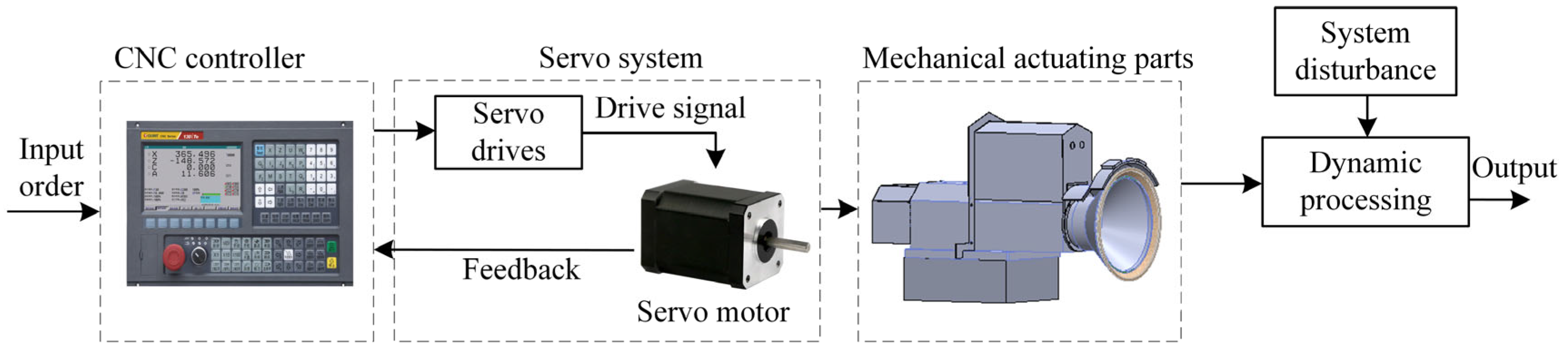
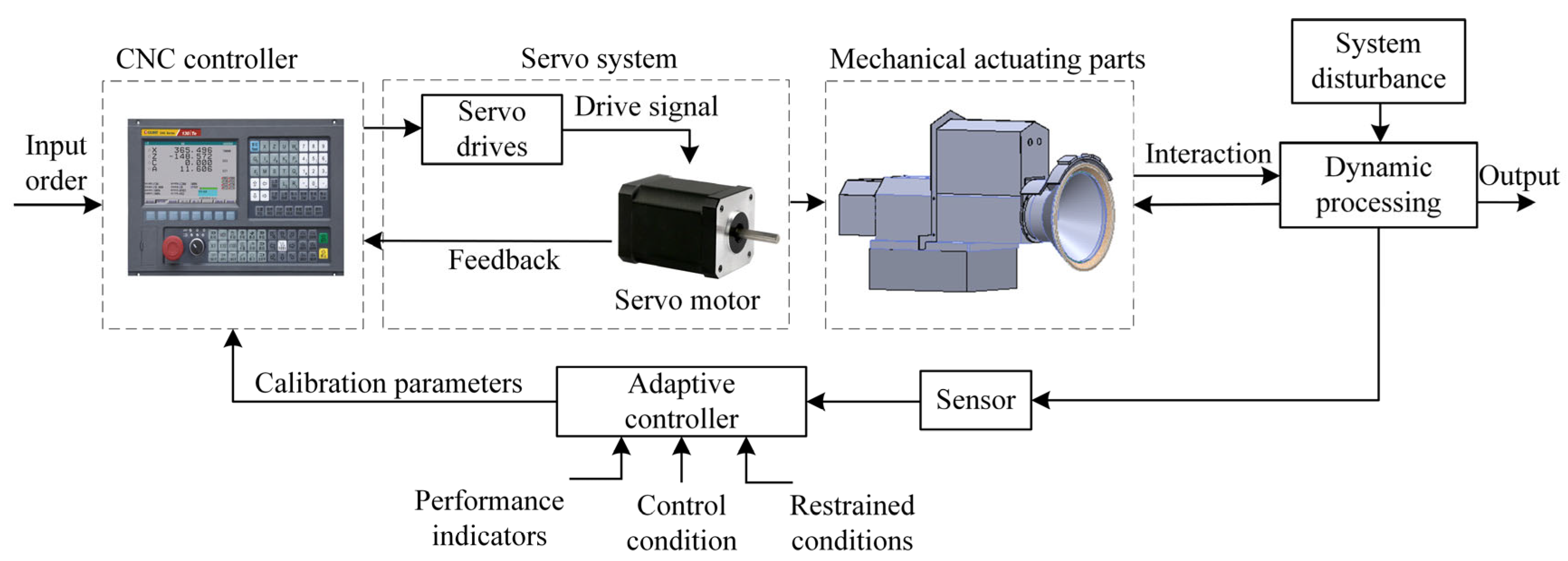
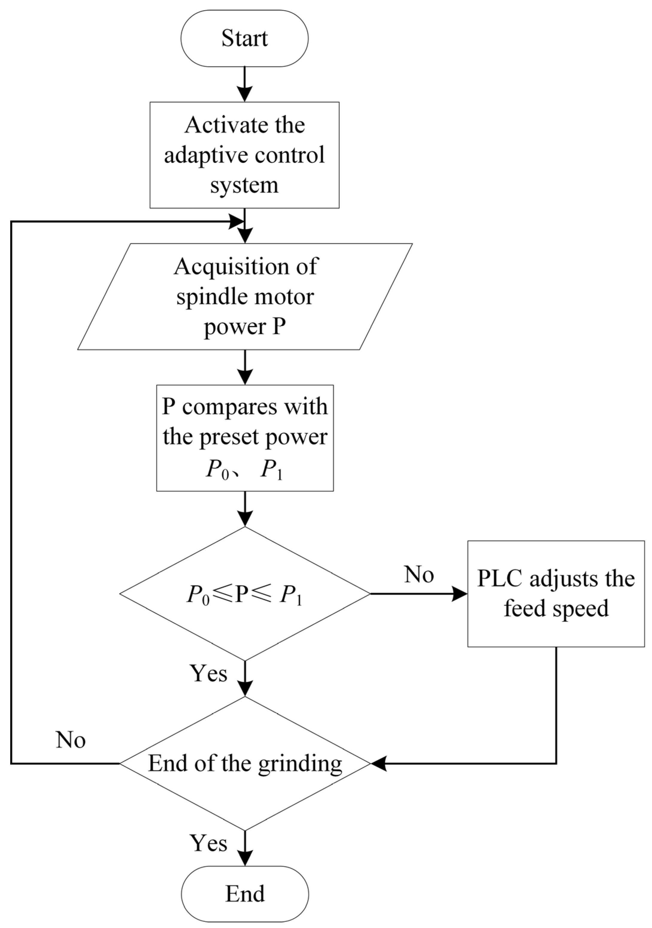
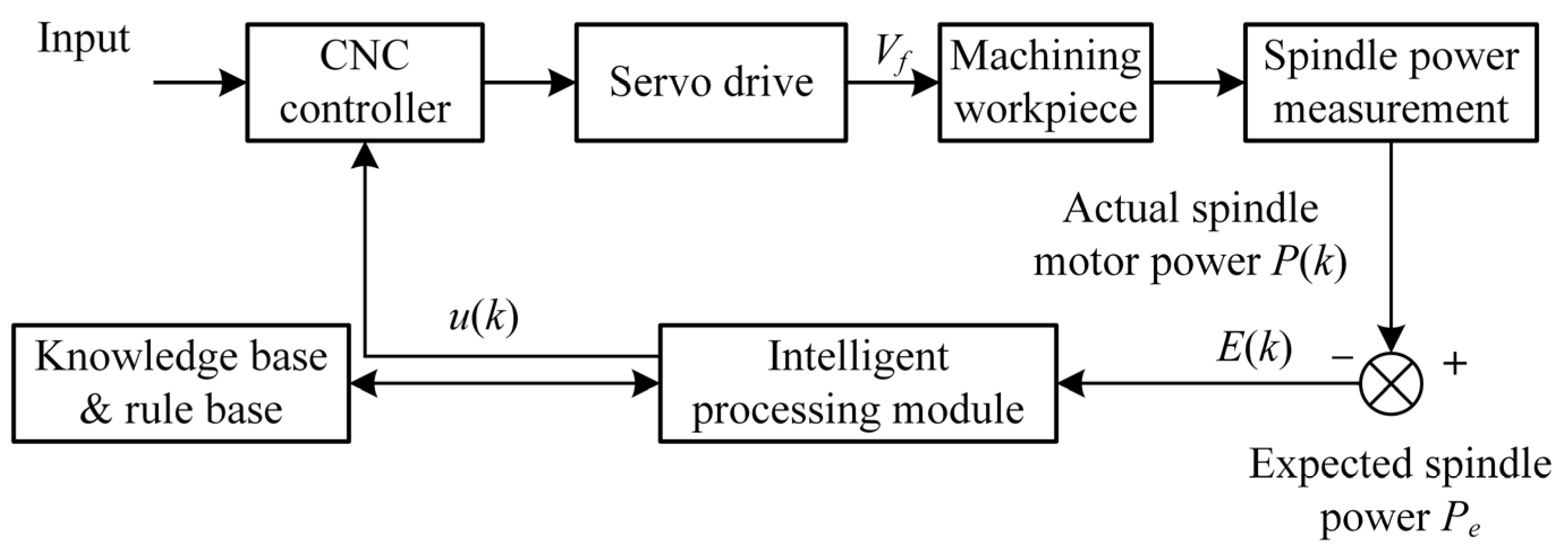
2.1. Adaptive Control Principle

Traditional grinding typically employs the constant feed rate control approach. As depicted in Figure 1, the conventional CNC system for machine tools is a semi-closed-loop control system. Only position and velocity feedback are available in the servo unit. By monitoring and controlling the location and speed of the motor, the machine operates solely by the desired trajectory and speed. However, there is a process–machine interaction in the precision grinding of cemented carbide tools; for instance, there is a coupling between the grinding force and the machine tool [23,24]. This effect will always compromise processing stability. The conventional CNC machine tool technology is inadequate for the grinding of cemented carbide, due to its complexity. If the feed rate is too high, the machining quality of the workpiece will be impacted by an increase in surface roughness and surface burning. Simultaneously, the wheel’s wear will accelerate, and the wheel itself will shatter. Reducing the feed rate will harm the processing efficiency.
Adaptive control of the machining process is an excellent method for addressing the aforementioned issues. As illustrated in Figure 2, the adaptive control system in this research considers the process–machine relationship. In an unexpected random environment, it can continuously detect the machining process variables of the machine tool (cutting force, torque, power, tool wear, dimensional accuracy, surface roughness, and so on). It can automatically alter the system’s processing parameters (cutting speed, feed speed) in a closed-loop manner to achieve the ideal condition.

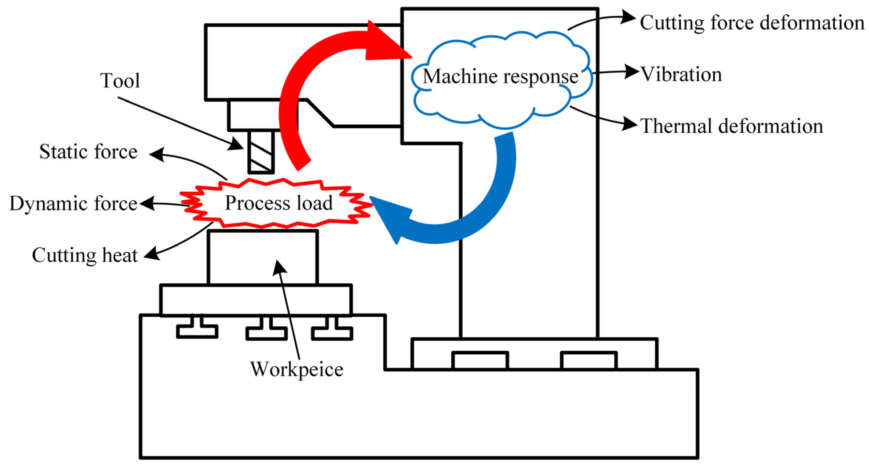
2.2. Principle of Process–Machine Interaction

In the precision grinding of carbide tools, the grinding process is not stable, and there is an interactive coupling between the grinding force and the machine tool. In the initial cutting stage, a transient grinding force excitation signal is generated, and the grinding force causes the initial deformation of the machine. When axial deformation of the grinding wheel occurs, the grinding wheel’s relative position changes. The grinding force decreases rapidly, due to the decrease in the relative grinding depth. At this time, the grinding force cannot support the initial deformation of the grinding wheel, and the grinding depth increases. Consequently, a closed-loop system based on iterative process–machine interactions was created, and the entire system was eventually stabilized. Figure 3 depicts the process–machine interaction principle. If the machine tool and the process are regarded as two independent branch systems, the state between them is stable. Because of this interaction, the system’s balance is destroyed, causing the tool’s and workpiece’s relative positions to vary throughout the machining process and, as a result, affecting processing quality [25].
The model of the machine’s structure can be characterized by the relevant differential equations. For ease of analysis, the end grinding machine in this study is simplified into a single degree of freedom system along the axial direction of the sand wheel, and its motion equation is as follows:
m x ¨ + c m x ˙ + k m x = F n
where x ¨ is the acceleration, x ˙ is the velocity, x is the displacement vector, Fn is the normal grinding force; m is the mass of the machine system, cm is the damping of the machine system and km is the stiffness of the machine system.
The grinding force Fn can be expressed as follows [26]:
F n = k c ( Δ + ( x ( t ) x ( t T ) ) )
where kc is the grinding stiffness factor, T is the grinding wheel rotation period. The grinding depth varies dynamically with time. The grinding depth consists of two parts, the static variable and dynamic variable; Δ is the static variation in the grinding depth and x(t) − x(t − T) is the dynamic variation in the grinding depth.
By substituting Equation (2) into Equation (1), we can obtain the following expression for the generic model of the system:
m x ¨ + c m x ˙ + k m x = k c ( Δ + ( x ( t ) x ( t T ) ) )
The interaction between the machine tool and the process has been detailed previously. During the machining procedure, the machine structure and the process are coupled and interact, and there is an exchange of physical quantities, such as force, heat, and deformation, between them. The interaction between the machine tool and the process impacts the stability of both systems. This work presents a method for adjusting the grinding wheel feed speed to adaptively control the grinding force to more precisely control the interaction between the machine structure and the process.

3. Grinding Force Monitoring Method and Experimental Verification

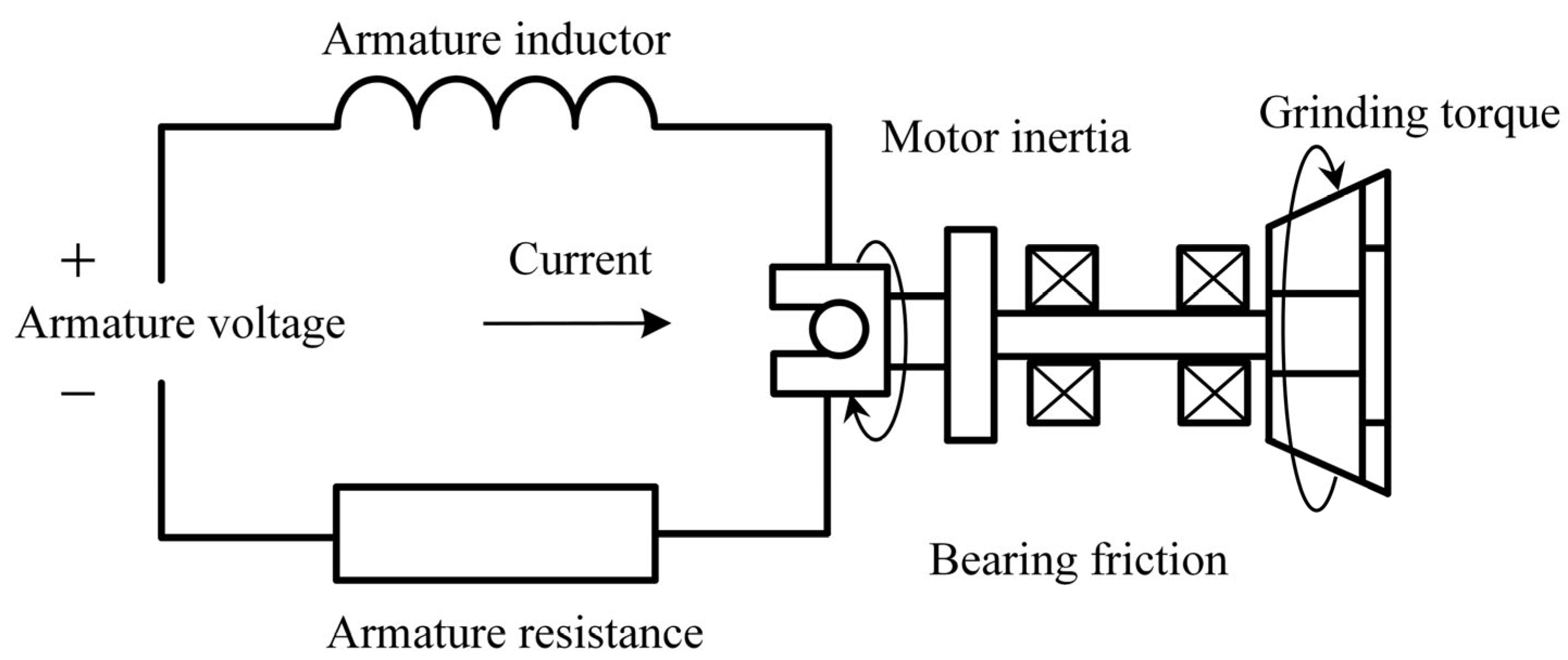
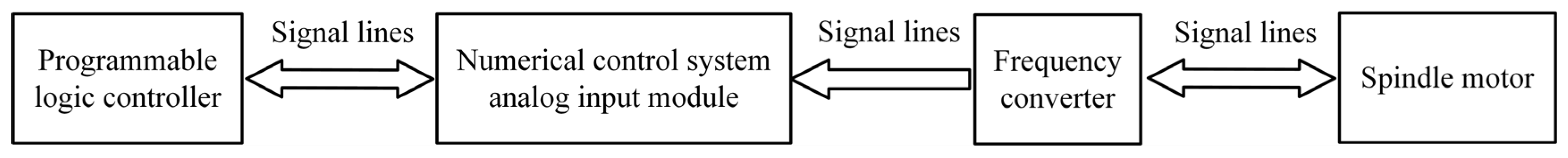
3.1. Grinding Force Monitoring Method

In the study of grinding machine mechanisms, the grinding force is the most important characteristic parameter. Controlling the grinding force has a significant impact on the machining process [27]. For adaptive control of grinding force to be realized, the dynamic grinding force must be monitored in real-time during the machining process. The grinding force signal is often monitored directly by a dynamometer in the current study [28,29]. The dynamometer used in grinding force detection mostly has issues with installation and dependability. The dynamometer is a sensitive component, and the operating environment significantly impacts measurement accuracy. As a result, a low-cost, simple-to-implement indirect measurement approach is required. Many experts have conducted extensive research on the indirect assessment of grinding force in recent years. Monitoring the spindle or servo motor’s current and power can effectively represent the grinding force [30].
There is a direct linear relationship between the grinding power signal and the tangential grinding force of the grinding wheel [31]. The grinding power signal is sensitive to the variation in the grinding wheel’s tangential force. Using the link between grinding force and spindle motor power, this research infers the grinding force by observing the spindle motor power. Figure 4 depicts the spindle drive chain of the grinding machine. The primary components of the drive chain system are the spindle motor, motor shaft, connection, and spindle. The signal from the motor armature regulates the spindle’s functioning [32].
The output torque of the spindle motor during the grinding operation comprises the cutting torque, the friction torque created by the bearings, and the transmission system’s momentum. The dynamic grinding force primarily impacts the entire system, the motor driving force, and the bearing friction. The system equation is written as follows [32]:
T = J d ω d t + B ω + F t R
where T is the output torque of the motor; J is the equivalent inertia of the motor; w is the angular speed of the spindle motor; B is the equivalent damping coefficient; Ft is the tangential grinding force; R is the radius of the grinding wheel. When the speed of the spindle is constant, J d ω / d t = 0. Under this condition, the system equation can be described as follows:
T = π n B 30 + F t R
According to the theory of electrical engineering,
T = P ω = 30 P π n
By substituting Equation (6) into Equation (5), we can obtain
F t = 900 P π 2 n 2 B 30 π n R
where Ft is the tangential grinding force; P is the power of the spindle motor; n is the speed of the motor; B is the equivalent damping coefficient; R is the radius of the grinding wheel.
When the motor speed is constant and the spindle system is stable, it can be observed from Equation (7) that the motor power and tangential grinding force have a simple linear relationship. The power of the spindle motor can accurately reflect the varying grinding force.
During the grinding process, the spindle motor’s power signal must be gathered to implement adaptive control of the grinding force. Figure 5 depicts the power acquisition module for motors.
The motor power acquisition module consists of a frequency converter, an analog input module of a numerical control system, and a PLC module, which performs the analog-to-digital conversion of the motor power. The frequency converter’s analog output module outputs motor power. The numerical control system’s analog input module receives the analog signal and completes the analog-to-digital conversion. Using system variables, a PLC may determine the spindle motor’s power.

3.2. Experimental Verification

According to Equation (7), it can be concluded that there is a simple linear relationship between grinding force and spindle motor power. In this study’s investigations, it was determined that the normal grinding force was significantly larger than the tangential grinding force and that the normal grinding force had a greater impact on the grinding process. To verify the mapping relationship between spindle motor power and grinding force, an indirect measurement experiment of grinding force was conducted on a 2MZK7150 CNC tool grinder (Hanjiang Machine Tool Co., Ltd., Hanzhong, China). The grinding wheel model utilized for the experiment was D64 (H250 D400). The diameter of the grinding wheel was 400 mm, and its width was 10 mm. The workpiece is a carbide insert with a thickness of 4.8 mm indexable. The insert has the shape of an equilateral triangle, with a 12.7 mm inner circle diameter. The type of the indexable carbide insert is SPGN150412. During the grinding process, the speed of the grinding wheel was 50 m/s. Utilizing a KISTLER 9272 force measuring instrument, the grinding forces were measured. The grinding parameters for the nine trials conducted under the aforementioned machining conditions are listed in Table 1.
The normal grinding force and spindle motor power were measured in accordance with Table 1′s grinding conditions. A regression analysis was performed on the acquired data to determine the indirectly measured grinding force. Figure 6 depicts the comparison between the actual grinding forces measured by the dynamometer and the results of the regression analysis.
As portrayed in Figure 6, the indirect grinding forces derived from spindle motor power and the actual grinding forces measured with a dynamometer are comparable. The maximum error does not exceed 10%, and the smallest error is approximately 0.96%. The experimental results indicate that the power of the spindle motor can indirectly reflect the fluctuation in grinding force.
Grinding force is controlled by the adaptive control system by altering the feed speed. A grinding force-feed speed experiment was carried out to reflect the variable pattern between feed speed and grinding force. A 2MZK7150 CNC indexable insert peripheral grinder was used for the cemented carbide tool grinding test. The experiment used a diamond grinding wheel with a diameter of 400 mm and a breadth of 10 mm. The diamond grinding wheel’s model number is D64(H250D400). The workpiece is a 4.8 mm thick indexable carbide insert. The insert is an equilateral triangle with a 12.7 mm inner circle diameter. SPGN150412 is the model number for an indexable carbide blade. The KISTLER 9272 dynamometer was utilized during the grinding operation to collect the grinding force. Table 2 shows the grinding process parameters.
The experimental results are displayed in Figure 7. When the feed speed reached 18 mm/min, the maximum grinding force was 131.68 N, and the blade surface was somewhat burned; when the feed speed reached 24 mm/min, the maximum grinding force was 169.56 N, and apparent burns on the surface of the workpiece were detected. Considering the surface quality and processing efficiency of the grinding, the grinding force can be regulated at 80–100 N, using the adaptive system of the machine tool. In addition, the experimental results demonstrate that in the grinding process, as the feed speed of the machine tool increases, the grinding force increases dramatically. It is achievable to control the grinding force by altering the feed speed.

4. Grinding Force Control Method and Experimental Verification

The grinding force is maintained between 80 and 100 N by the machine’s adaptive control system, based on past experimental findings. According to the mapping relationship between the grinding force and the spindle motor power, the respective preset powers P0 and P1 (P0 < P1) are determined.
The gathered power is then compared to the preset power, and the feed rate is modified based on the comparison’s outcome. Adaptive control flow is demonstrated in Figure 8.

4.1. Feed Rate Compensation

In this study, a PD controller is used to provide adaptive compensation of the feed speed. The expected spindle power is Pe, the actual spindle power is P(k), and the error value input to the intelligent processing module is E(k). The preset power P0 and P1 have been obtained above. The error value of the current sampling moment is represented as follows:
{ E ( k ) = P e P ( k ) , k = 1 , 2 , 3 P e = P 0 + P 1 2
Since the data collecting process is cyclical and discrete data are obtained, it is not possible to achieve differentiation. The posterior term difference approach is employed instead of differentiation. The standard PD controller u(k) can be expressed after discretization as follows:
u ( k ) = K p [ E ( k ) + T d E ( k ) E ( k 1 ) T ]
where u(k) is the output value at the current sampling moment, Kp is the proportional gain of the PD controller, Td is the differential time constant of the PD controller, T is the sampling period, E(k) is the error value of the current sampling moment, and E(k − 1) is the error value of the previous sampling moment.
If K p T d T = K d , we can obtain the following equation:
u ( k ) = K p e ( k ) + K d [ e ( k ) e ( k 1 ) ]
where Kd is the differentiation factor.
In the equation u1(k) = KpE(k), u2(k) = Kd[E(k) − E(k − 1)], u1(k) is the proportional compensation and u2(k) is the differential compensation.
The feed rate compensation process is presented in Figure 9. According to the error E(k) between the expressed spindle power and the actual spindle power, the compensation u(k) is calculated, and then the feed rate Vf is adjusted to maintain E(k) within the error limit.
In the actual compensation process, the error limit is set to Elim, and the sign of the compensation direction is introduced as follows:
S c ( k ) = s i g n ( | E ( k ) | E l i m )
When Sc(k) = 1, a positive compensation will be performed; when Sc(k) = −1, a negative compensation will be performed; when Sc(k) = 0, no compensation will be performed.
In the actual compensation process, compensation deviations often occur. In this study, referring to the work of Chen T. et al. [33], a nonlinear weighting method is introduced to correct the compensation to improve the reliability of the compensation. The evaluation factor R(k) of proportional compensation u1(k) is introduced and the expression is as follows:
R ( k ) = p ( k ) p ( k 1 ) u 1 ( k ) ,   p ( 0 ) = P e
When R(k) = 1, the system achieves optimal compensation; when R(k) < 1, it means that the compensation has no effect, but increases the error, at this time, R(k) = 0. When R(k) > 3, it means that the compensation exceeds the actual demand, and to avoid affecting the system stability, one must ensure that R(k) = 3.
To avoid sudden power changes caused by accidental factors, the compensation effect of the past k times is considered comprehensively, and a comprehensive compensation factor R ¯ regarding compensation is introduced.
R ¯ = i = 1 k w i R ( i ) i = 1 k w i = i = 1 k Q i R ( i ) , i = 1 k Q i = 1
where Qi is the weight value of R(i). When 0.8 R ¯ < 1 , it means that the previous compensation is reasonable at the moment; when R ¯ < 0.8 , it means that the overall compensation is not adequate and needs to be increased; when R ¯ > 1 , it means that the overall compensation exceeds the actual demand and needs to be reduced. We can adjust the proportional compensation u1(k) based on the evaluation results to obtain the following equation:
u 1 ( k ) = q E ( k 1 ) R ¯
where q is the adjustment factor, and the initial value of q is 1. The value of q is adjusted according to the evaluation of the comprehensive compensation factor.
{ q = q 2 Δ q , R ¯ 2 q = q Δ q , 1 R ¯ < 2 q = q , 0.8 R ¯ < 1 q = q + Δ q , 0.6 R ¯ < 0.8 q = q + 2 Δ q , R ¯ < 0.6
where Δq is the regulation increment of the regulation factor q, taken as 0.2 in this study.
By combining Equation (10) and Equation (14), the compensation value u(k) is as follows:
u ( k ) = q E ( k 1 ) R ¯ + K d [ E ( k ) E ( k 1 ) ]

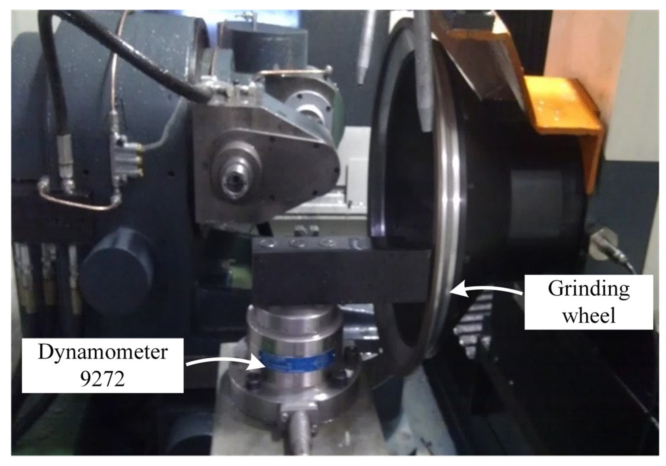
4.2. Experimental Conditions

A grinding experiment was carried out to validate the effectiveness of the adaptive control system for the grinding force. The cemented carbide tool grinding test was conducted out using a 2MZK7150 CNC tool grinder. The grinding wheel model adopted in the experiment is D64(H250 × D400). The diameter of the grinding wheel is 400 mm and the width of the grinding wheel is 10 mm. The workpiece is an indexable carbide insert with a thickness of 4.8 mm. The shape of the insert is an equilateral triangle with an inner circle diameter of 12.7 mm. The model of indexable carbide blade is SPGN150412. During the grinding process, the spindle speed was 2000 r/min, and the grinding depth was 0.5 mm. The KISTLER 9272 force measurement system was used to collect the grinding force. Under the above machining conditions, the comparison experiments of grinding without an adaptive control system and adaptive control system were carried out. When there is no adaptive control in the machining process, two sets of experiments are set up, the feed rate for the first set of experiments is 2.4 mm/min, and the feed rate for the second set of experiments is 12 mm/min. The feed speed remained constant throughout the machining process. Under adaptive control conditions, the initial feed rate was set to 7.2 mm/min. The experimental device is shown in Figure 10.

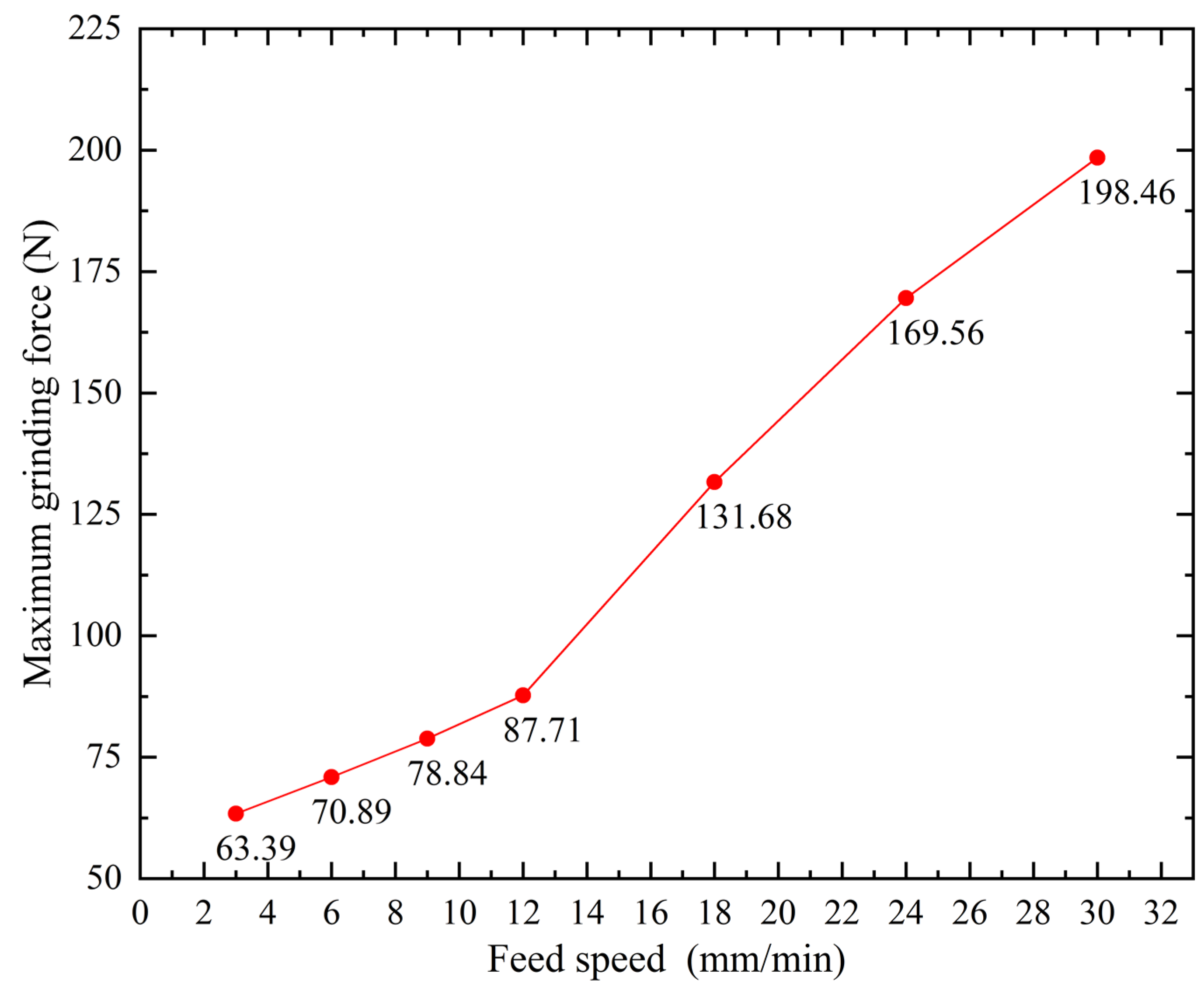
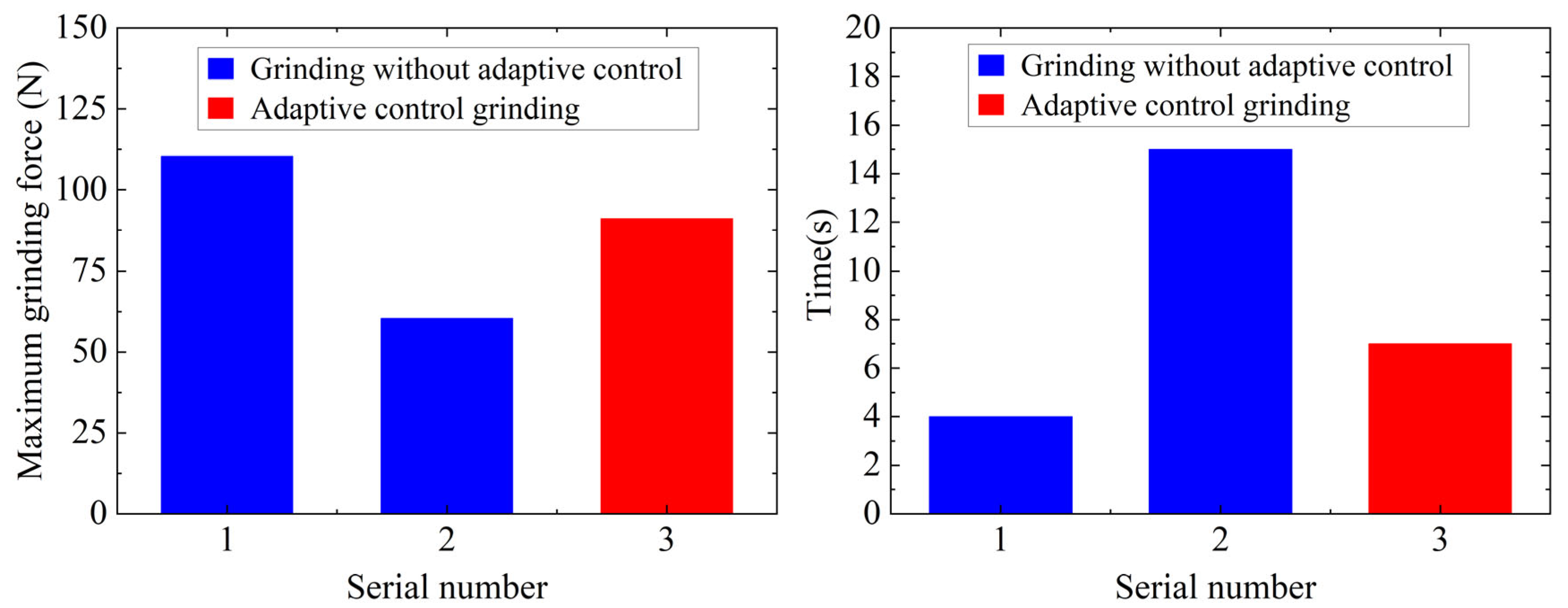
4.3. Experimental Results

We compared and analyzed the results of the three groups of experiments. It can be observed in Figure 11 that, without adaptive control, the maximum grinding force is 60.39 N and the processing time is 15 s when the feed rate is 2.4 mm/min. When the feed rate is 12 mm/min, the maximum grinding force is 110.44 N and the processing time is 4 s. At this time, the maximum grinding force exceeds 100 N. Under the adaptive control condition, the initial feed rate is set to 7.2 mm/min. When the grinding wheel first cuts the workpiece, the grinding force is small, and the feed speed is increased to 10 mm/min by adjusting the adaptive control system. With the change in grinding force, the adaptive control system automatically adjusts the feed speed. In the grinding process, the maximum grinding force is 91.16 N and the processing time is 7 s.
Collectively, these results imply that, with the adaptive control system adjusted, the grinding force can be maintained within the optimal range, the surface quality of the workpiece is ensured, and the processing time can be reduced to increase processing efficiency. Therefore, the grinding force adaptive control system has achieved its intended purpose and may be used to increase production efficiency in the actual process.

5. Conclusions

The feed rate is mostly constant in conventional indexable turning tool grinding. The constant feed rate, on the other hand, cannot be matched with the complex grinding criteria. To address this issue, this paper investigates a new method of adaptive grinding force control and performs a carbide tool grinding test on a 2MZK7150 CNC tool grinder to examine the grinding results, drawing the following conclusions:
(1)
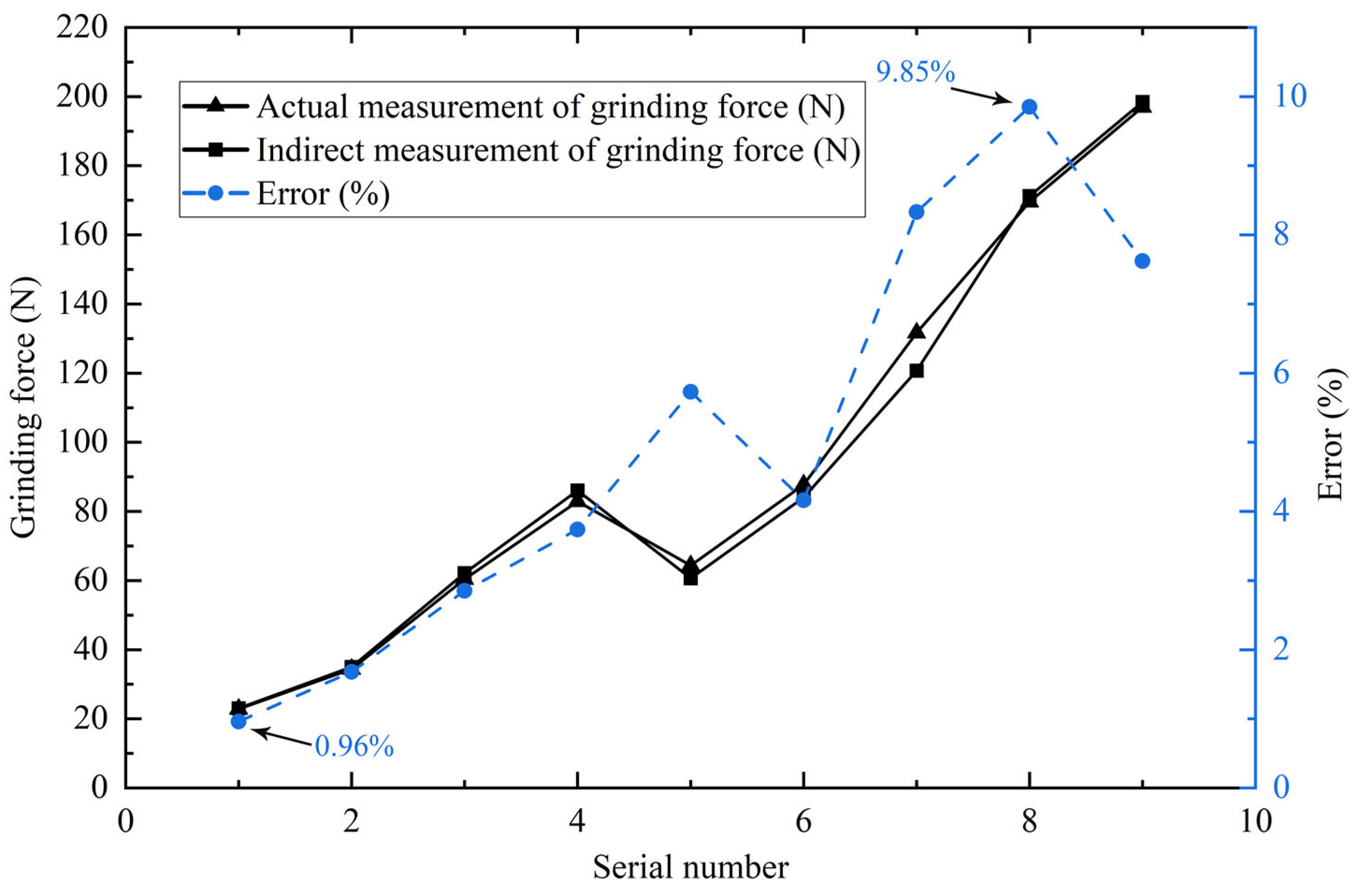
The indirect monitoring method of grinding force based on spindle motor power is proposed, and the monitoring effect is good, with a maximum error of 9.85% and a minimum error of 0.96%;
(2)
Considering the process–machine interaction, an adaptive control approach for the grinding force is proposed, along with the controller’s compensating rules. The adaptive control system of grinding force substantially improves the grinding process’s efficiency;
(3)
Only a general explanation of the machine tool process interaction is provided in this work. Further research is required to completely comprehend the impact of the machine tool process interaction on the control effect;
(4)
A disadvantage of this work is that the adaptive control experiment is only conducted at 2000 r/min and 0.5mm grinding depth. Due to the fact that the effects of the machine tool process interaction on the control effect may vary under different processing conditions, it will be necessary to conduct more research that takes these variables into account.

Author Contributions

Conceptualization, X.Z. and W.F.; methodology, X.Z. and P.C.; validation, P.C.; formal analysis, M.F.; investigation, P.C.; writing—original draft preparation, P.C.; writing—review and editing, M.F. and S.L.; visualization, S.L. and X.P.; Supervision, X.Z.; project administration, X.Z.; funding acquisition, X.Z. All authors have read and agreed to the published version of the manuscript.

Funding

The authors disclosed receipt of the following financial support for the research, authorship, and/or publication of this article: This work was funded by National Natural Science Foundation of China (grant number 51605337 and 5210051192); Natural Science Foundation of Zhejiang Province (grant number LQ19E050010 and LQ22E050008); Natural Science Foundation of Wenzhou City (CN), grant number G20210001 and Wenzhou major scientific and technological innovation project, grant number ZG2020029.

Data Availability Statement

Data are all contained within the article. All data are fully available without restriction.

Conflicts of Interest

The authors declare no conflict of interest.

References

  1. Nguyen, V.H.; Shin, S.G.; Ko, S.L. Development of CAM software to design and grind indexable inserts. Int. J. Precis. Eng. Manuf. 2015, 16, 869–876. [Google Scholar] [CrossRef]
  2. Zhan, Y.; Tian, X.; Xu, Y.; Jia, M. Study on the specific grinding energy of cemented carbide (YG8) grinding with a vitrified diamond wheel in high speed regime. Int. J. Abrasive Technol. 2019, 9, 286. [Google Scholar] [CrossRef]
  3. Cai, S.; Yao, B.; Zheng, Q.; Cai, Z.; He, Z. Dynamic grinding force model for carbide insert peripheral grinding based on grain element method. J. Manuf. Process. 2020, 58, 1200–1210. [Google Scholar] [CrossRef]
  4. Dai, S.; Zhao, Y.; Ji, W.; Mu, J.; Hu, F. Constant force control for aluminum wheel hub grinding based on ESO + backstepping. Ind. Robot 2022, 49, 824–834. [Google Scholar] [CrossRef]
  5. Zhang, M.; Chen, T.; Tan, Y.; Lu, J. An adaptive grinding method for precision-cast blades with geometric deviation. Int. J. Adv. Des. Manuf. Technol. 2020, 108, 7–8. [Google Scholar] [CrossRef]
  6. Feng, G.; Wang, T.; Huang, Q.; Guo, W.; Liu, R. Experimental study on ultra-precision grinding characteristics of WC-Ni hard metals. Proc. Inst. Mech. Eng. Part B 2019, 234, 600–609. [Google Scholar] [CrossRef]
  7. Wang, L.; Hu, Z.; Yu, Y.; Xu, X. Evaluation of Double-Sided Planetary Grinding Using Diamond Wheels for Sapphire Substrates. Crystals 2018, 8, 262. [Google Scholar] [CrossRef]
  8. Yang, F.; Sun, Y.; Wang, Y.; Mo, H.; Zhu, L.; Yuan, H.; Lu, B.; Zhang, G.; Zuo, D. Modeling and Experimental Verification of Surface Roughness for Grinding Monocrystalline Silicon Lens. Adv. Theory Simul. 2022, 5, 2100422. [Google Scholar] [CrossRef]
  9. Liu, T.; Deng, Z.; Lv, L.; She, S.; Liu, W.; Luo, C. Experimental Analysis of Process Parameter Effects on Vibrations in the High-Speed Grinding of a Camshaft. Stroj. Vestn.—J. Mech. Eng. 2020, 66, 175–183. [Google Scholar] [CrossRef]
  10. Wu, C.; Guo, W.; Wu, Z.; Wang, Q.; Li, B. Ductility-oriented high-speed grinding of silicon carbide and process design for quality and damage control with higher efficiency. Int. J. Adv. Manuf. Technol. 2019, 105, 2771–2784. [Google Scholar] [CrossRef]
  11. Maeng, S.; Lee, P.A.; Bo, H.K.; Min, S. An analytical model for grinding force prediction in ultra-precision machining of WC with PCD micro grinding tool. Int. J. Precis. Eng. Manuf.-Green Technol. 2020, 7, 1031–1045. [Google Scholar] [CrossRef]
  12. Junejo, F. The application of artificial intelligence in grinding operation using sensor fusion. Int. J. Geomate 2017, 12, 11–18. [Google Scholar] [CrossRef]
  13. Jiang, C.; Li, H.; Mai, Y.; Guo, D. Material removal monitoring in precision cylindrical plunge grinding using acoustic emission signal. Proc. Inst. Mech. Eng. Part C 2014, 228, 715–722. [Google Scholar] [CrossRef]
  14. Teti, R.; Jemielniak, K.; O’Donnell, G.; Dornfeld, D. Advanced monitoring of machining operations. CIRP Ann. 2010, 59, 717–739. [Google Scholar] [CrossRef]
  15. Liu, C.S.; Li, Y.A. Evaluation of grinding wheel loading phenomena by using acoustic emission signals. Int. J. Adv. Manuf. Technol. 2018, 99, 1109–1117. [Google Scholar] [CrossRef]
  16. Chi, Y.; Li, H.; Chen, X. In-process monitoring and analysis of bearing outer race way grinding based on the power signal. Proc. Inst. Mech. Eng. Part B 2016, 231, 2622–2635. [Google Scholar] [CrossRef]
  17. Ma, Y.C.; Yang, J.G. Multi-Sensor Intelligent Monitoring of High-Speed Grinding for Brittle and Hard Materials. Appl. Mech. Mater. 2015, 741, 309–314. [Google Scholar] [CrossRef]
  18. Lee, C.H.; Jwo, J.S.; Hsieh, H.Y.; Lin, C.S. An intelligent system for grinding wheel condition monitoring based on machining sound and deep learning. IEEE Access 2020, 8, 58279–58289. [Google Scholar] [CrossRef]
  19. Zhang, G.; Liu, M.; Li, J.; Ming, W.Y.; Shao, X.Y.; Huang, Y. Multi-objective optimization for surface grinding process using a hybrid particle swarm optimization algorithm. Int. J. Adv. Des. Manuf. Technol. 2014, 71, 1861–1872. [Google Scholar] [CrossRef]
  20. Zhang, Z.S.; Yao, B.; Zhang, X.L.; Yao, B.S. Accuracy analysis of grinding indexable inserts related to the centrifugal force of high speed abrasive wheel. Adv. Mater. Res. 2012, 422, 606–609. [Google Scholar] [CrossRef]
  21. Zhang, X.-L.; Yao, B.; Chen, B.-Q.; Sun, W.-F.; Wang, M.-M.; Luo, Q. Thermo-mechanical properties of bowl-shaped grinding wheel and machining error compensation for grinding indexable inserts. J. Cent. South Univ. 2015, 22, 3830–3836. [Google Scholar] [CrossRef]
  22. Fountas, N.A.; Vaxevanidis, N.M. Optimization of Abrasive Flow Nano-Finishing Processes by Adopting Artificial Viral Intelligence. J. Manuf. Mater. Process. 2021, 5, 22. [Google Scholar] [CrossRef]
  23. Ji, Y.; Wang, X.; Liu, Z.; Wang, H.; Feng, W.; Wang, Y.; Liu, S. Five-axis flank milling stability prediction by considering the tool-workpiece interactions and speed effect. Int. J. Adv. Des. Manuf. Technol. 2020, 108, 2037–2060. [Google Scholar] [CrossRef]
  24. Aurich, J.C.; Biermann, D.; Blum, H.; Brecher, C.; Carstensen, C.; Denkena, B.; Klocke, F.; Kröger, M.; Steinmann, P.; Weinert, K. Modelling and simulation of process: Machine interaction in grinding. Prod. Eng. 2009, 3, 111–120. [Google Scholar] [CrossRef]
  25. Brecher, C.; Esser, M.; Witt, S. Interaction of manufacturing process and machine tool. CIRP Ann. 2009, 58, 588–607. [Google Scholar] [CrossRef]
  26. Aurich, J.C.; Kirsch, B. Kinematic simulation of high-performance grinding for analysis of chip parameters of single grains. CIRP J. Maunf. Sci. Technol. 2012, 5, 164–174. [Google Scholar] [CrossRef]
  27. Zhang, X.; Chen, P.; Zhang, J.; Li, S.; Zhou, H. Study on grinding force of Si3N4 ceramics in random rotation grinding with truncated polyhedral grains. Int. J. Adv. Manuf. Technol. 2021, 115, 3139–3148. [Google Scholar] [CrossRef]
  28. Li, Z.; Zhang, F.; Luo, X.; Guo, X.; Cai, Y.; Chang, W.; Sun, J. A new grinding force model for micro grinding RB-SiC ceramic with grinding wheel topography as an input. Micromachines 2018, 9, 368. [Google Scholar] [CrossRef]
  29. Manea, H.; Cheng, X.; Ling, S.; Zheng, G.; Gao, X. Model for predicting the micro-grinding force of k9 glass based on material removal mechanisms. Micromachines 2020, 11, 969. [Google Scholar] [CrossRef]
  30. Li, D.; Xu, M.; Wei, C.; Hu, D.; Xu, L. A dynamic threshold-based fuzzy adaptive control algorithm for hard sphere grinding. Int. J. Adv. Manuf. Technol. 2012, 60, 923–932. [Google Scholar] [CrossRef]
  31. Hecker, R.L.; Liang, S.Y.; Wu, X.J.; Xia, P.; Jin, D.G.W. Grinding force and power modeling based on chip thickness analysis. Int. J. Adv. Manuf. Technol. 2007, 33, 449–459. [Google Scholar] [CrossRef]
  32. Mao, X.Y.; Liu, H.Q.; Bin, L.I. Time-frequency analysis and detecting method research on milling force token signal in spindle current signal. Sci. China 2009, 52, 2810–2813. [Google Scholar] [CrossRef]
  33. Chen, T.; Tian, X. Dimensional error prediction and its intelligent soft pre-compensation in batch manufacture. Int. J. Adv. Manuf. Technol. 2015, 77, 281–288. [Google Scholar] [CrossRef]
Figure 1. Traditional CNC system of machine tool.
Machines 10 00802 g001
Figure 2. Machine tool adaptive control system.
Machines 10 00802 g002
Figure 3. Principle of interaction between the machine tool and process.
Machines 10 00802 g003
Figure 4. CNC tool grinding machine spindle drive chain.
Machines 10 00802 g004
Figure 5. Spindle motor acquisition module.
Machines 10 00802 g005
Figure 6. Comparison between the actual measured grinding force and the indirectly measured grinding force.
Machines 10 00802 g006
Figure 7. Variation curve of maximum grinding force under the certain feed speed.
Machines 10 00802 g007
Figure 8. Flowchart of adaptive control of the grinding force.
Machines 10 00802 g008
Figure 9. Scheme of intelligent compensation solution for feed rate.
Machines 10 00802 g009
Figure 10. Grinding experimental device.
Machines 10 00802 g010
Figure 11. Comparison of experimental results.
Machines 10 00802 g011
Table 1. Processing test table.
Serial NumberFeed Speed (mm/min)Grinding Depth (mm)
12.40.08
2120.05
32.40.4
46.00.2
52.40.2
612.00.4
718.00.4
824.00.4
930.00.4
Table 2. Grinding process parameters.
Linear Speed of Grinding Wheel (m/s)Grinding Depth (mm)Feed Speed (mm/min)
500.43, 6, 9, 12, 18, 24, 30
Publisher’s Note: MDPI stays neutral with regard to jurisdictional claims in published maps and institutional affiliations.

