Communication

Loco-Manipulation Control for Arm-Mounted Quadruped Robots: Dynamic and Kinematic Strategies

1
School of Optoelectronic Engineering and Instrumentation Science, Dalian University of Technology, Dalian 116024, China
2
School of Mechanical Engineering, Dalian University of Technology, Dalian 116024, China
*
Author to whom correspondence should be addressed.
Machines 2022, 10(8), 719; https://doi.org/10.3390/machines10080719
Submission received: 4 July 2022 / Revised: 11 August 2022 / Accepted: 18 August 2022 / Published: 22 August 2022
(This article belongs to the Section Robotics, Mechatronics and Intelligent Machines)

Abstract

:
The studies on quadruped robots equipped with arms are still rare at the moment. The interaction between the arm and the quadrupedal platform needs to be handled by whole-body controllers. This paper presents an optimization-based dynamic whole-body controller to solve the problem of when the robot stands still for manipulation. In order to reduce the strong interaction when the robot is trotting, we keep using the whole-body controller to handle locomotion control and resort to joint PD controllers for the arm’s manipulation coupled with the mobile base on the kinematic level. Simulation results validate the expected locomotion and manipulation functionalities in both manipulation mode and loco-manipulation mode. The proposed control strategies are able to use the redundancy to perform multiple tasks in a dynamic system as such with 24 degrees of freedom.

1. Introduction

Legged robots have been a hot spot both in academics and in industry for a while because of their advantages in locomotion compared with wheeled and tracked robots. Although we saw some impressive works among humanoid robots in terms of balancing control and manipulation versatility [1,2,3,4], quadruped robots are a better option for commercialization benefiting from larger support area and lower hardware cost than humanoid robots. Quadruped robots have shown tremendous potential application values in industrial scenarios and at home. However, quadruped robots have limited manipulation capabilities without an extra arm mounted. A few works can be found in the literature where researchers exploit transferring legs to perform manipulation [5,6,7]. The leg mechanism of a multi-legged robot usually does not have large enough reachable workspace due to the limited degrees of freedom (DoFs). Furthermore, it is difficult to realize simultaneous locomotion and manipulation without a dedicated manipulator. Equipping a quadruped robot with an extra arm will greatly extend the deployment scope in the real world.
The typical quadruped robot equipped with an arm is Boston Dynamics’s Spot [8]. Spot may be the most successful quadruped robot in terms of loco-manipulation capability. However, they never made the methods used to control this robot public. Ref. [9] combines a Spot robot and a Kinova arm. Since Spot gives restricted access of their controller to the users, conducting high-level motion planning is the best choice for the users treating Spot as a black box. In an early work [10] from Boston Dynamics, the hydraulically driven robot BigDog demonstrated cinderblock throwing maneuvers with a human-arm-like manipulator during trotting using trajectory optimization methods. Another hydraulic quadruped robot, HyQ, also demonstrates its loco-manipulation capability during static walking [11]. In that work, the authors optimize the contact forces to control the robot by counting the arm as disturbances. A teleoperation technique that constructs the mapping between human motion and quadrupedal manipulation is validated in [12].
The whole-body controller (WBC) is a coordinate control method for articulated robots which plays a key role in legged locomotion, particularly when the reference trajectories are generated by reduced order models [13,14]. The WBC computes physically feasible joint torque commands tracking task-space trajectories without using inverse kinematics. Since the equations of motion become linear when considering only one time step forward, Quadratic Programming (QP) is widely used in different WBC methods. We can classify the existing WBC methods into the weighted QP (WQP) method [14,15,16], hierarchical QP (HQP) method [17,18,19,20] and their mixture. WQP relies on the weight matrix to prioritize coupled tasks. The problem with WQP is the difficulty in tuning weight matrices. HQP strictly prioritizes multiple tasks along with different constraints by using null-space projectors without using any weight matrices. Although solving multiple QPs increases the computation burden, the control loop can still run at kilohertz even with dozens of DoFs. Ref. [18] involves centroidal momentum dynamics along with full rigid-body dynamics to increase the stability of a humanoid robot. Ref. [21] extends their HQP controller to a quadruped robot ANYmal equipped with a kinova Jaco arm. However, they only use three QPs to control eight tasks. Therefore, their controller should be a combination of HQP and WQP. Additionally, they can use the single controller for loco-manipulation because the centroidal momentum dynamics are not involved.
In this paper, we present a WBC control framework for an arm-mounted quadruped robot, as shown in Figure 1. The arm motion affects the centroidal momentum dynamics and disturbs the balance control in locomotion. We propose two control modes: manipulation mode and loco-manipulation mode. In the manipulation mode, we use an HQP to control the arm, legs and the base subject to the whole rigid-body dynamics of the robot. It leads to the automatic adaption of lower prioritized tasks to satisfy tasks with higher priorities. In the loco-manipulation mode, in order to overcome the effect on locomotion from the arm, we resort to kinematic decoupling. The arm will be controlled by joint PD controllers to track joint trajectories computed by inverse kinematics, while the base and the legs are controlled by the HQP controller. In other words, the loco-manipulation control mode mixes dynamic and kinematic strategies.
The rest of the paper is organized as follows. In Section 2, the coordinate variables, joint-space dynamics and centroidal momentum dynamics are presented. The proposed control framework is detailed in Section 3. Section 4 describes the simulation platforms and the simulation results along with an edited video clip showing the loco-manipulation demonstrations. Section 5 concludes the paper.

2. Model Formulation

Following the dynamic modeling library Pinocchio [22,23], we define the generalized coordinate vector q and generalized velocity vector v as
q = W x b q b q j S E ( 3 ) × R n , v = W x ˙ b B ω b q ˙ j R 6 + n
where W x b R 3 represents the position of the base with respect to the world frame, expressed in the world frame, q b denotes the unit quaternion describing the base orientation with respect to the world frame, W x ˙ b R 3 is the base velocity with respect to the world frame expressed in world frame as well, B ω b R 3 is the base angular velocity with respect to the world frame expressed in the base frame, q j R n and q ˙ j R n denote the joint angles and angular velocities. For the quadruped robot with an arm, in our case, n = 18 , where the arm has 6 DoFs. As usual, the joint-space dynamic equations of a floating base robot are written as
M ( q ) v ˙ + h ( q , v ) = S τ + J c ( q ) λ
J c ( q ) q ¨ + J ˙ c ( q ) q ˙ = 0
where M ( q ) R ( 6 + n ) × ( 6 + n ) , h ( q , v ) R 6 + n are the inertia matrix and the combination of Coriolis, centrifugal and gravity terms. τ R n represents the actuated joint torques, S = 0 6 × n I n × n is the selection matrix, J c ( q ) R 3 m × ( 6 + n ) is the constraint Jacobian matrix, λ R 3 m denotes the contact forces and m denotes the number of contact points. The dynamic Equation (2) is subject to a kinematic constraint described by (3) that guarantees no motion of the contact points.
The joint-space dynamic Equation (2) of a quadruped robot can be split into their floating-base and actuated parts
M b ( q ) v ˙ + h b ( q , v ) = J c , b ( q ) λ
M j ( q ) v ˙ + h j ( q , v ) = τ + J c , j ( q ) λ
where M b ( q ) R 6 × ( 6 + n ) , h b ( q , v ) R 6 and J c , b ( q ) R 3 m × 6 denote the floating base components of the dynamic matrices, while M j ( q ) R n × ( 6 + n ) , h j ( q , v ) R n and J c , j ( q ) R 3 m × n represent the actuated components. For simplification, we use M b , h b , J c , b , M j , h j and J c , j to represent M b ( q ) , h b ( q , v ) , J c , b ( q ) , M j ( q ) , h j ( q , v ) and J c , j ( q ) .
The joint-space floating-base dynamics (4) can be converted into the CoM-space dynamics, i.e., the so-called centroidal momentum dynamics
h ˙ G = A G ( q ) v ˙ + A ˙ G ( q , v ) v
where h ˙ G = l ˙ G k ˙ G R 6 is the derivative of centroidal momentum composed of linear component and angular component. A G ( q ) R 6 × ( 6 + n ) denotes the centroidal momentum matrix, which was proposed by Orin et al. [24] originally. A ˙ G ( q , v ˙ ) is the changing rate of the centroidal momentum. Please refer to [25] for the details of the computation of A G ( q ) and A ˙ G ( q , v ˙ ) . We use A G and A ˙ G to represent A G ( q ) and A ˙ G ( q , v ˙ ) as well.
The important value of (6) is that it establishes the mapping relationship between CoM acceleration p ¨ CoM and the generalized coordinates v , since
l ˙ G = m p ¨ CoM
which enables us to generate joint-space commands to track the CoM trajectories.
Note that τ is determined by Equation (5) as follows:
τ = M j v ˙ + h j J c , j λ
Therefore, we can use Equation (4) to represent the entire dynamics of the system in the optimization-based control method described in the following section.

3. Materials and Methods

HQP is employed as the WBC method in this work. HQP uses the null-space projection to prioritize different tasks for a redundant system. We formulate each control task as a QP in a least-square manner
min y i 1 2 A i y i a i 2 2 s . t . lb i B i y i ub i
where y i is the same decision variable vector for all the QPs in which the components could be control inputs and system states.
The final optimal solution of the entire HQP problem is
y = Λ ( y i ) = y 1 + N 1 y 2 + + N 1 N 2 N i 1 y i
where N i = N ( A i ) stands for the null-space projector of matrix A i . In this paper, we use the pseudo-inverse to compose the null-space projector, i.e., N i = I i A i + A i , where I i denotes identity matrices. Obviously, the first task has the highest priority, while the last one has the lowest priority based on the meaning of null-space projection.
In our case, the decision variable is y = v ˙ λ R 6 + n + 3 m , since we use the floating-base dynamics as a constraint in the HQP. The torque commands τ that will be sent to the motors can be obtained from the optimal solution y based on Equation (8)
τ cmd = M j v ˙ + h j J c , j λ
However, for arm-mounted quadruped robots, the problem arises here: manipulation and locomotion have the same priority in dynamic walking. Fortunately, the arm in our case has 6 DoFs that are enough for manipulation tasks. Thereby, we create two control modes: in a standing scenario, we use a single HQP controller to coordinate the base and the arm focusing on manipulation; during dynamic walking, we switch to a kinematically decoupled control strategy where the arm is controlled by joint PD controllers while the HQP is in charge of the locomotion. The control structure is depicted in Figure 2.

3.1. Manipulation Mode

In this control mode, the whole system is controlled by an HQP controller. The first QP is assigned to the dynamic feasibility. We formulate the floating dynamics and no contact motion equality constraint into the QP cost function
1 2 M b J c , b J c 0 A 1 y h b J ˙ c q ˙ a 1 2 2
The inequality constraints include the linearized friction cone constraints, unilateral constraints and torque limits. Here, we refer to our previous works [26,27] for the details of those constraints. In particular, joint angles can be constrained to avoid singularity configurations. We use Taylor expansion to approximate q j ( t ) around the current time t 0
q j ( t ) q j ( t 0 ) + q ˙ j Δ t + 1 2 q ¨ j Δ t 2
Furthermore, the joint angle constraints can be written as
1 2 Δ t 2 S j y q j , max q j ( t 0 ) q ˙ j ( t 0 ) Δ t
q j , min q j ( t 0 ) q ˙ j ( t 0 ) Δ t 1 2 Δ t 2 S j y
where S j = 0 n × 6 I n × n 0 n × 3 m , Δ t = k t c and t c means the control cycle. We can tune k to set the softness of this constraint in practice.
All the inequality constraints can be combined together into one equation
lb B y ub
Equation (16) needs to be included in all the QPs of the HQP.
For any trajectory tracking tasks, we add task space PD control along with the reference acceleration variables
x ¨ cmd = x ¨ ref + K d ( x ˙ ref e ˙ ) + K p ( x ref x )
where x ref represents the reference trajectory, and K p and K d denote the PD gains.
The QPs for trajectory tracking has the same cost function type
1 2 J i 0 A i y x ¨ cmd + J ˙ i q ˙ a i 2 2
where J i could be the Jacobian matrix of the end-effector, the base or the swing feet (in loco-manipulation case). Table 1 lists the prioritized tasks in the manipulation mode. The control of the end-effector is assigned to the second QP with the following cost function
1 2 J e 0 A 2 y x ¨ e , cmd + J ˙ e q ˙ a 2 2 2
where J e R 6 × ( 6 + n ) represents the end-effector Jacobian matrix. The reference trajectory of the end-effector is defined in the world frame and is generated by integrating the velocity commands coming from the joystick. For the base, we have
1 2 J b 0 A 3 y x ¨ b , cmd + J ˙ b q ˙ a 3 2 2
Actually, J b = I 6 × 6 0 6 × n , leading to J ˙ b = 0 . Thereby, Equation (20) can be reduced to
1 2 J b 0 y x ¨ b , cmd 2 2

3.2. Loco-Manipulation Mode

In order to mitigate the interaction between the arm and the base during dynamic walking, we switch to joint PD control for the arm. However, the base and the legs are still controlled by the HQP controller, satisfying the same equality and inequality constraints as in manipulation mode. The task priorities are listed in Table 2. Compared with Table 1, one difference is the replacement of the end-effector motion tracking by swing foot motion tracking. The QP for swing foot motion tracking has the following cost function:
1 2 J f 0 A 2 y x ¨ f , cmd + J ˙ f q ˙ a 2 2 2
where J f is the stack of the swing feet’s Jacobian matrices. The reference trajectories of the swing feet and the CoM are generated by a linear Model Predictive Control (MPC) algorithm based on the linear inverted pendulum (LIP) model (see our previous work [27]). Since the LIP model is a reduced order model, the HQP control not only plays the role of trajectory tracking but also guarantees the physical feasibility by satisfying the full dynamic model Equation (4).
Moreover, we only control the base orientation in this QP because the CoM position is controlled by the next QP in the centroidal momentum dynamics. By multiplying a selection matrix, we can select the last three rows of the cost function (21) to track the base orientation only
1 2 S o J b 0 A 3 y S o x ¨ b , cmd a 3 2 2
where S o = 0 3 × 3 I 3 × 3 . In addition, we set the base orientation to be constant. However, it may be sacrificed to guarantee the accuracy of the end-effector’s trajectory tracking because the base has lower priority than the end-effector.
Similar to trajectory tracking, based on Equations (6) and (7), we can formulate a QP to track desired centroidal momentum with the following cost function:
1 2 A G 0 A 4 y h ˙ G , cmd + A ˙ G v a 4 2 2
where h ˙ G , cmd = l ˙ G , cmd k ˙ G , cmd is the commanded derivative of centroidal momentum composed of the linear component and angular component that are defined as
l ˙ G , cmd = m [ p ¨ CoM , ref + D l ( p ˙ CoM , ref p ˙ CoM ) + K l ( p CoM , ref p CoM ) ]
k ˙ G , cmd = k ˙ G , ref + D k ( k G , ref k G )
where p CoM , ref denotes the desired CoM position generated by motion planners, p CoM is the actual CoM position observed by state estimators, m denotes the total mass of the robot, k G , ref and k G mean the desired and actual angular momentum, respectively, and K l and D i ( i = l , k ) are feedback gains. It should be noted that we set the desired CoM position to be constant in the manipulation mode, leading to P ˙ CoM , ref = 0 and P ¨ CoM , ref = 0 .
The end-effector’s reference trajectory is defined in the world frame as well. However, we compute the end-effector pose relative to the base and then compute the joint positions by using the arm’s inverse kinematics instead of the whole-body inverse kinematics
q arm , ref = I K arm ( W x e , ref W x b )
where I K arm ( · ) represents the inverse kinematics of the arm, W x e , ref R 6 is the end-effector’s desired pose in world and W x b R 6 denotes the measured base pose in world frame. Note that we use Euler angles to express the orientation. That is the reason why W x b and W x e have six dimensions. Then, we use joint PD controllers to track the reference joint trajectories q arm , ref of each arm motor.
In summary, the loco-manipulation mode uses full dynamics to keep balancing and stability of locomotion. On the other hand, the arm is controlled by joint PD controllers, but the arm’s position is related to the base on the kinematic level. Therefore, we can keep the end-effector at a fixed position in the world frame while the robot is walking (see Section 4).

3.3. Simulation Platforms

We build a quadruped robot’s virtual model, which is 50 cm tall in default configuration and weights 25 Kg, as shown in Figure 1. A six-DoFs Kinova Jaco 2 robot arm is integrated to the robot, changing the total weight to 30 Kg. The ROS (Robot Operation System) is used to build the simulation environment, which connects different modules, including the controller, the planner, the joystick interface, the Gazebo simulator and the logging tools. The dynamic modeling library Pinocchio is employed to generate the matrices and vectors of the dynamic equations online. The open-source OSQP solver [28] solves all the QPs in the proposed controller within 1 ms. The control cycle is set to be 500 Hz. The computer running the simulation has a Intel(R) Core(TM) i9-10900K CPU, 16 GB memory and Ubuntu 20.04 operation system. Moreover, the controller can run at kilohertz on a Raspberry 4 without running a simulator.

4. Results

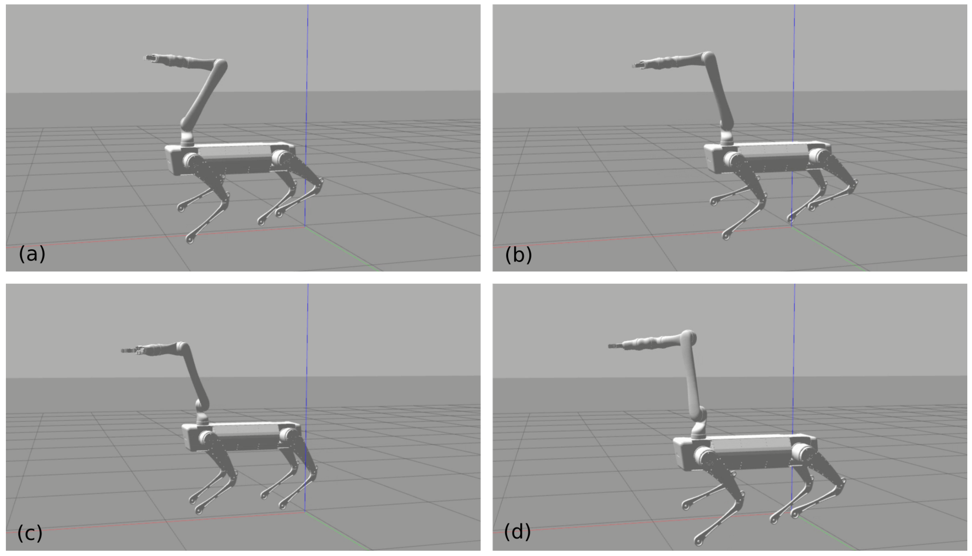
4.1. Torso Pose Adaptation in Manipulation Mode

In the manipulation mode, the end-effector has higher priority than the base, so that the torso could automatically adapt to the end-effector’s motion when the end-effector reaches its own limits. This will extend the kinematic reach of the end-effector significantly by using the redundancy of the whole system. Figure 3 shows the snapshots of the experiment where we commanded the end-effector to reach the ground and reach as far as it can. We can see that the torso changes its pose to extend the end-effector’s reachability. Figure 4 shows the position variation during this experiment. The base was controlled to be fixed at the initial position. We can see that the control error was very small until the base complied with end-effector since the base has lower priority. The control error is much less than the results shown in [11]. At around 40 s, the end-effector was at the lowest point where the base height lowed as well. At around 70 s, the end-effector reached the farthest position with torso adaptation clearly. In fact, we set the position bound relative to the original position when starting manipulation to stop the end-effector moving further than the system’s limits. Otherwise, the robot would fall over since the torso follows the end-effector anyway. The Supplementary Materials content a recorded video to show the simulation results.

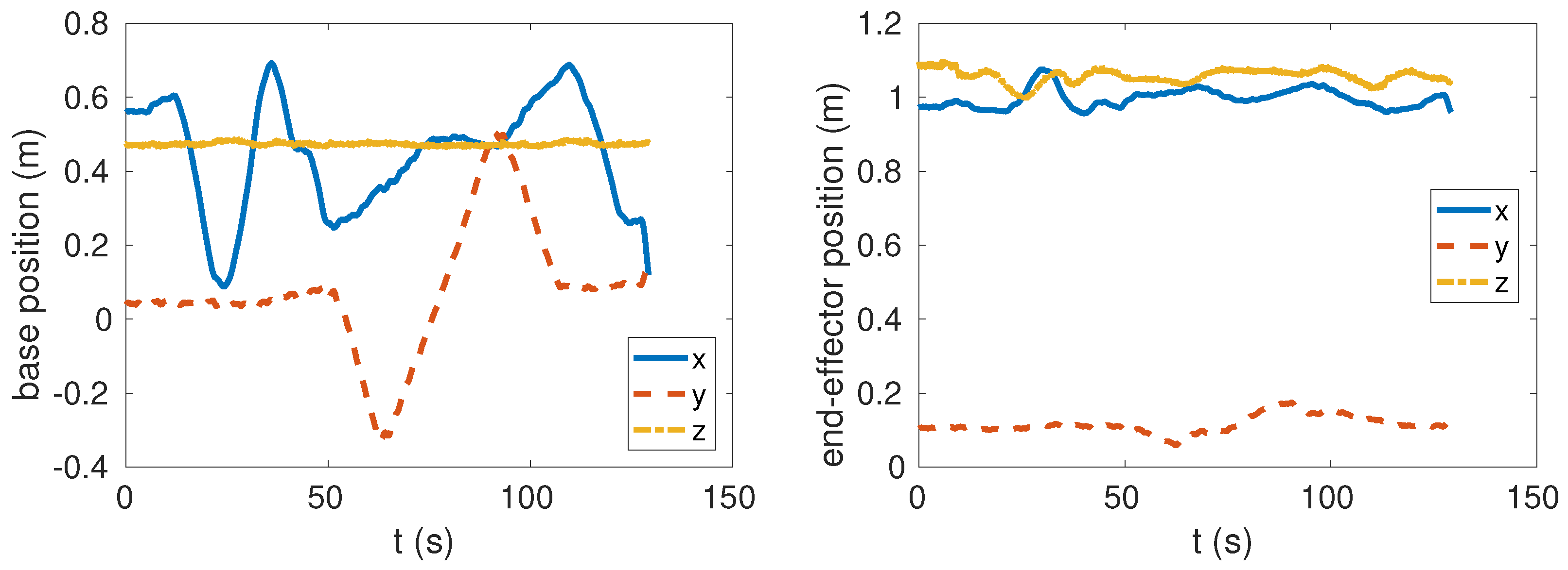
4.2. Keeping the End-Effector Fixed in Loco-Manipulation Mode

In this experiment, we show the coordination between the arm and the base in locomotion. A common test for this functionality is called the “chicken head” motion [7,29]. It means that the end-effector is aimed to be fixed in place while the base is moving around. The snapshots in Figure 5 shows four typical moments in this experiment. Figure 6 plots the measured positions of the base and the end-effector in the experiment. The robot was trotting backward and forward and moving to the right side and back to the left side. While the base travels more than a half meter, the end-effector’s deviation from its original position is fewer than 10 cm. Furthermore, the result proves the robot can perform a manipulation task and locomotion simultaneously, i.e., the loco-manipulation functionality.

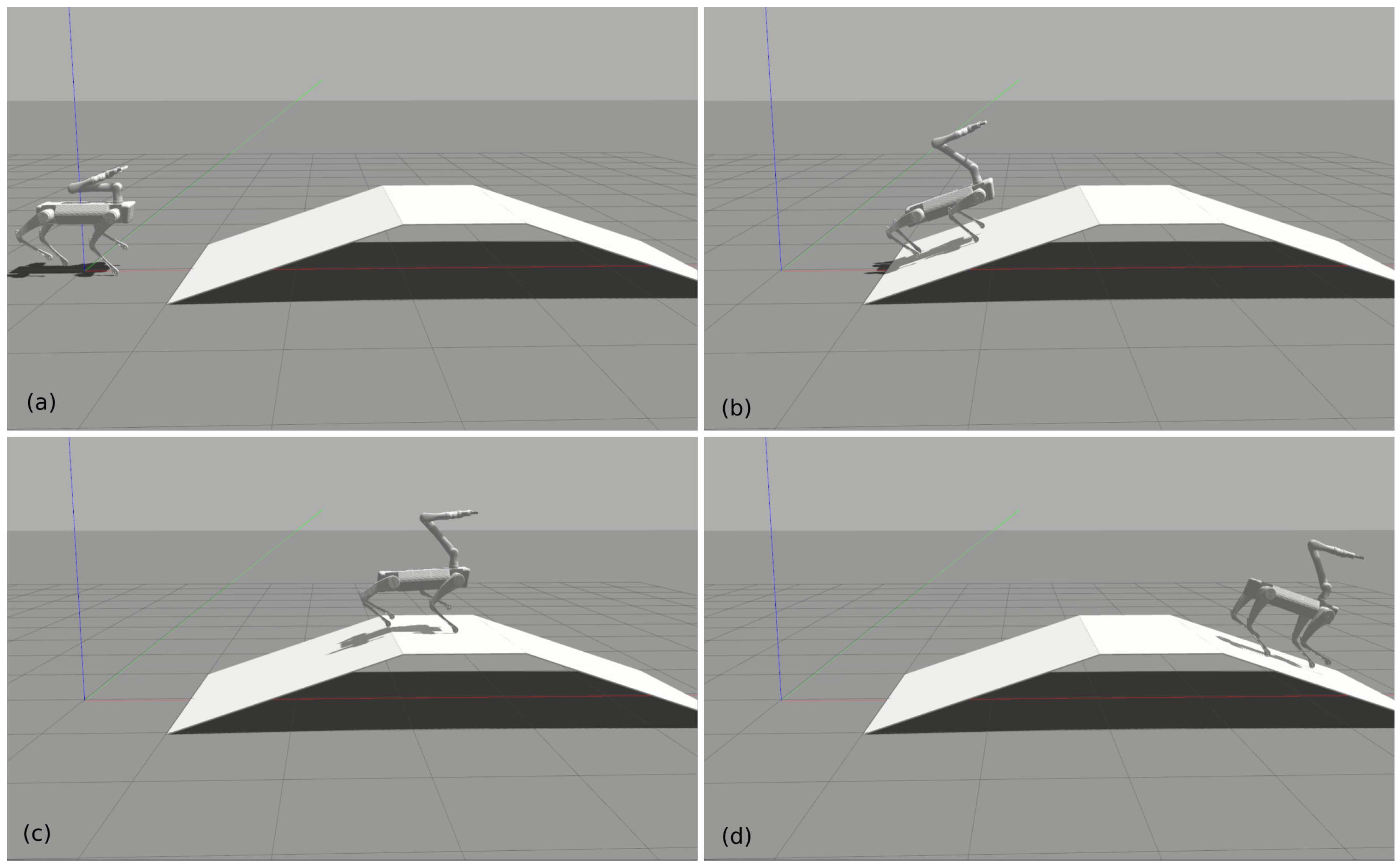
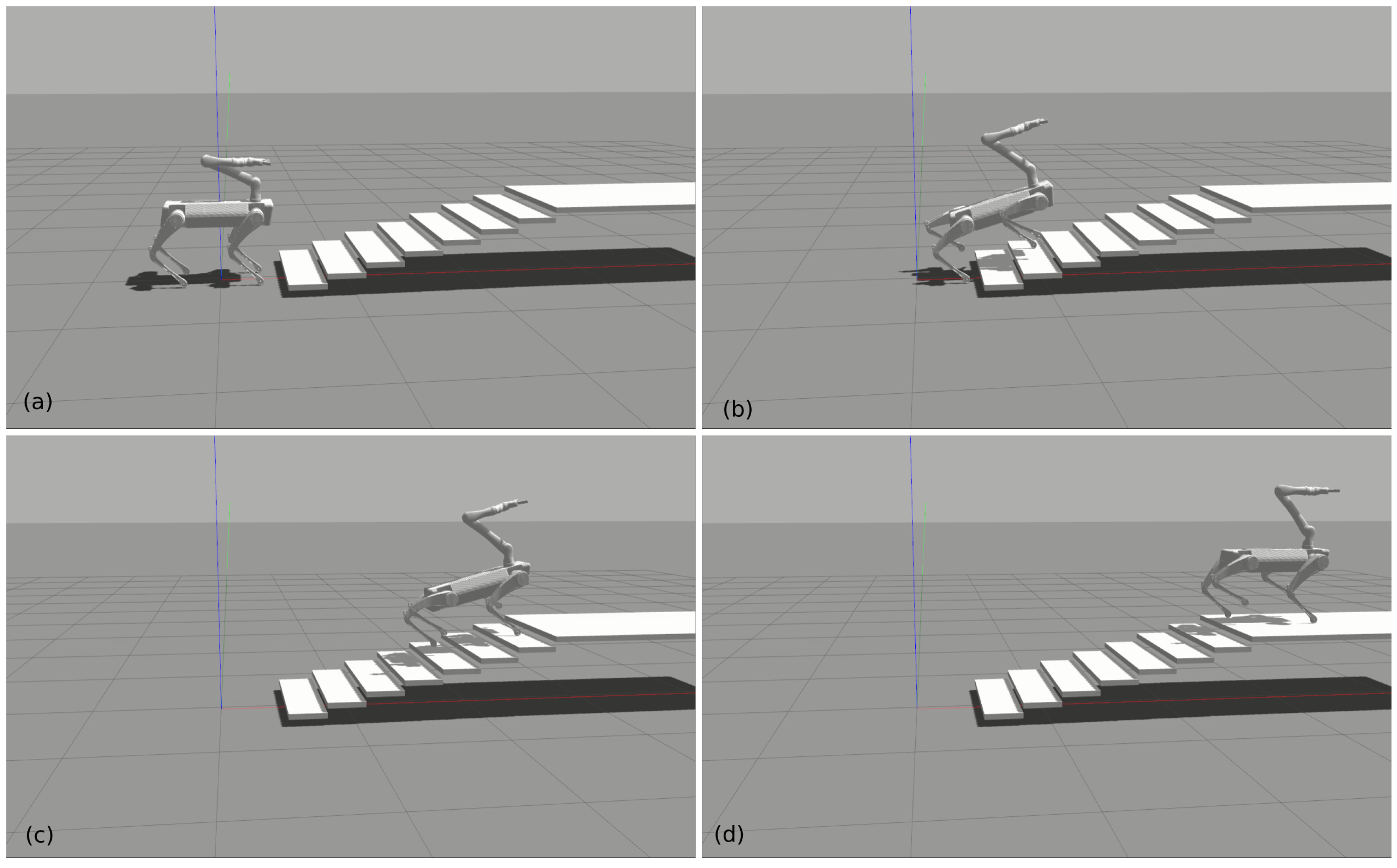
4.3. Locomotion Demonstrations

In this subsection, we demonstrate the locomotion capability to traverse challenging terrains. Firstly, we tested the robot on an up-and-down 20-degree slope as shown in Figure 7. The robot was able to blindly trot up and down the slope even in the condition of reducing the friction coefficient to 0.5. In the second test, the robot blindly trotted up stairs quickly as shown in Figure 8. Each stair step has a 10 cm height and 30 cm width. Since the robot was not assisted by any perception technique, we did not try to make the robot climb stairs with a higher step height. Moreover, motion planners play an more important role in challenging terrains such as steep stairs. The two tests prove the proposed controller can handle the interaction between the arm and the quadrupedal platform in dynamic gaits. The locomotion capability of the robot does not degrade after mounting the arm, benefiting from the full dynamics involved in the HQP controller.

5. Conclusions

Dynamic and kinematic consistent strategies are proposed to tackle the arising problems after equipping a quadruped robot with an arm. The arm’s motion affects the balance control in dynamic walking. On the other hand, the mobile base also affects the arm’s manipulation accuracy. The HQP controller properly handles the trajectory tracking tasks and satisfies the equality and inequality constraints by solving cascaded QPs. That is good enough for the manipulation mode where the feet are standing still on the ground. When the robot is walking, we solve the interaction problem by a kinematic solution and inverse kinematics. The arm switches to use joint PD controllers. Meanwhile, the balance control still takes into account the arm by constraining the HQP with the full dynamics. The workspace extension experiment, “chicken head” experiment, slope walking and stair climbing experiments show the effectiveness of the proposed controllers for simultaneous manipulation and locomotion. The comparison between our method and the existing methods highlights the advantages of the proposed algorithm in terms of control performance and simplicity in tuning control parameters. The future work will focus on perception assistant motion planning and real-world deployments where the IMU sensors should be integrated to increase the state estimation accuracy, as shown in [30].

Supplementary Materials

The following supporting information can be downloaded at: https://www.mdpi.com/article/10.3390/machines10080719/s1, Video S1: Recorded simulation video clips.

Author Contributions

Conceptualization, G.X.; methodology, G.X.; software, G.X. and F.Z.; validation, G.X., F.Z. and K.Q.; formal analysis, G.X.; investigation, G.X.; resources, G.X.; data curation, G.X.; writing—original draft preparation, G.X.; writing—review and editing, G.X. and K.Q.; visualization, G.X.; supervision, G.X.; project administration, G.X.; funding acquisition, G.X. and K.Q. All authors have read and agreed to the published version of the manuscript.

Funding

This research was funded by the Fundamental Research Funds for the Central Universities (No. 82232025). The APC was funded by the Fundamental Research Funds for the Central Universities (No. 82232025).

Institutional Review Board Statement

Not applicable.

Informed Consent Statement

Not applicable.

Data Availability Statement

Not applicable.

Conflicts of Interest

The authors declare no conflict of interest.

Abbreviations

The following abbreviations are used in this manuscript:
PDProportional derivative
DoFDegree of freedom
WBCWhole-body controller
QPQuadratic programming
WQPWeighted quadratic programming
HQPHierarchical quadratic programming
CoMCenter of mass
MPCModel predictive control
LIPLinear inverted pendulum
ROSRobot operation system
IMUInertia measurement unit
CPUCentral processing unit

References

  1. Atkeson, C.G.; Babu, B.P.W.; Banerjee, N.; Berenson, D.; Bove, C.P.; Cui, X.; DeDonato, M.; Du, R.; Feng, S.; Franklin, P.; et al. No falls, no resets: Reliable humanoid behavior in the DARPA robotics challenge. In Proceedings of the 2015 IEEE-RAS 15th International Conference on Humanoid Robots (Humanoids), Seoul, Korea, 3–5 November 2015; pp. 623–630. [Google Scholar]
  2. Kuindersma, S.; Deits, R.; Fallon, M.; Valenzuela, A.; Dai, H.; Permenter, F.; Koolen, T.; Marion, P.; Tedrake, R. Optimization-based locomotion planning, estimation, and control design for the atlas humanoid robot. Auton. Robot. 2016, 40, 429–455. [Google Scholar] [CrossRef]
  3. Yang, Y.; Merkt, W.; Ferrolho, H.; Ivan, V.; Vijayakumar, S. Efficient humanoid motion planning on uneven terrain using paired forward-inverse dynamic reachability maps. IEEE Robot. Autom. Lett. 2017, 2, 2279–2286. [Google Scholar] [CrossRef]
  4. Henze, B.; Roa, M.A.; Ott, C. Passivity-based whole-body balancing for torque-controlled humanoid robots in multi-contact scenarios. Int. J. Robot. Res. 2016, 35, 1522–1543. [Google Scholar] [CrossRef]
  5. Whitman, J.; Su, S.; Coros, S.; Ansari, A.; Choset, H. Generating gaits for simultaneous locomotion and manipulation. In Proceedings of the 2017 IEEE/RSJ International Conference on Intelligent Robots and Systems (IROS), Vancouver, UK, 24–28 September 2017; pp. 2723–2729. [Google Scholar]
  6. Roennau, A.; Heppner, G.; Nowicki, M.; Dillmann, R. LAURON V: A versatile six-legged walking robot with advanced maneuverability. In Proceedings of the 2014 IEEE/ASME International Conference on Advanced Intelligent Mechatronics, Besancon, France, 8–11 July 2014; pp. 82–87. [Google Scholar]
  7. Xin, G.; Smith, J.; Rytz, D.; Wolfslag, W.; Lin, H.C.; Mistry, M. Bounded haptic teleoperation of a quadruped robot’s foot posture for sensing and manipulation. In Proceedings of the 2020 IEEE International Conference on Robotics and Automation (ICRA), Paris, France, 31 May –31 August 2020; pp. 1431–1437. [Google Scholar]
  8. Boston Dynamics. Introducing SpotMini. 2016. Available online: https://www.youtube.com/watch?v=tf7IEVTDjng&t=59s (accessed on 1 January 2020).
  9. Zimmermann, S.; Poranne, R.; Coros, S. Go Fetch!-Dynamic grasps using Boston Dynamics Spot with external robotic arm. In Proceedings of the 2021 IEEE International Conference on Robotics and Automation (ICRA), Xi’an, China, 30 May–5 June 2021; pp. 4488–4494. [Google Scholar]
  10. Abe, Y.; Stephens, B.; Murphy, M.P.; Rizzi, A.A. Dynamic whole-body robotic manipulation. In Unmanned Systems Technology XV; Karlsen, R.E., Gage, D.W., Shoemaker, C.M., Gerhart, G.R., Eds.; International Society for Optics and Photonics, SPIE: Bellingham, WA, USA, 2013; Volume 8741, pp. 280–290. [Google Scholar]
  11. Rehman, B.U.; Focchi, M.; Lee, J.; Dallali, H.; Caldwell, D.G.; Semini, C. Towards a multi-legged mobile manipulator. In Proceedings of the 2016 IEEE International Conference on Robotics and Automation (ICRA), Stockholm, Sweden, 16–21 May 2016; pp. 3618–3624. [Google Scholar]
  12. Peers, C.; Motawei, M.; Richardson, R.; Zhou, C. Development of a Teleoperative Quadrupedal Manipulator. In Proceedings of the UK-RAS21 Conference: “Robotics at Home” Proceedings, Leeds, UK, 2 June 2021. [Google Scholar]
  13. Kim, D.; Di Carlo, J.; Katz, B.; Bledt, G.; Kim, S. Highly Dynamic Quadruped Locomotion via Whole-Body Impulse Control and Model Predictive Control. arXiv 2019, arXiv:1909.06586. [Google Scholar]
  14. Xin, S.; Orsolino, R.; Tsagarakis, N.G. Online Relative Footstep Optimization for Legged Robots Dynamic Walking Using Discrete-Time Model Predictive Control. In Proceedings of the IROS, Macao, China, 4–8 November 2019; pp. 513–520. [Google Scholar]
  15. Feng, S.; Whitman, E.; Xinjilefu, X.; Atkeson, C.G. Optimization based full body control for the atlas robot. In Proceedings of the IEEE-RAS International Conference on Humanoid Robots, Madrid, Spain, 18–20 November 2014; pp. 120–127. [Google Scholar] [CrossRef]
  16. Di Carlo, J.; Wensing, P.M.; Katz, B.; Bledt, G.; Kim, S. Dynamic locomotion in the mit cheetah 3 through convex model-predictive control. In Proceedings of the 2018 IEEE/RSJ International Conference on Intelligent Robots and Systems (IROS), Madrid, Spain, 1–5 October 2018; pp. 1–9. [Google Scholar]
  17. De Lasa, M.; Mordatch, I.; Hertzmann, A. Feature-based locomotion controllers. ACM Trans. Graph. (TOG) 2010, 29, 131. [Google Scholar] [CrossRef]
  18. Herzog, A.; Rotella, N.; Mason, S.; Grimminger, F.; Schaal, S.; Righetti, L. Momentum control with hierarchical inverse dynamics on a torque-controlled humanoid. Auton. Robot. 2016, 40, 473–491. [Google Scholar] [CrossRef] [Green Version]
  19. Dario Bellicoso, C.; Gehring, C.; Hwangbo, J.; Fankhauser, P.; Hutter, M. Perception-less terrain adaptation through whole body control and hierarchical optimization. In Proceedings of the IEEE-RAS International Conference on Humanoid Robots, Cancun, Mexico, 15–17 November 2016; pp. 558–564. [Google Scholar] [CrossRef] [Green Version]
  20. Del Prete, A.; Nori, F.; Metta, G.; Natale, L. Prioritized motion–force control of constrained fully-actuated robots: “Task Space Inverse Dynamics”. Robot. Auton. Syst. 2015, 63, 150–157. [Google Scholar] [CrossRef] [Green Version]
  21. Bellicoso, C.D.; Kramer, K.; Stäuble, M.; Sako, D.; Jenelten, F.; Bjelonic, F.; Hutter, M. ALMA-Articulated Locomotion and Manipulation for a Torque-Controllable Robot. In Proceedings of the International Conference on Robotics and Automation (ICRA 2019), Montreal, QC, Canada, 20–24 May 2019. [Google Scholar]
  22. Carpentier, J.; Valenza, F.; Mansard, N. Pinocchio: Fast forward and Inverse Dynamics for Poly-Articulated Systems. 2015–2019. Available online: https://stack-of-tasks.github.io/pinocchio (accessed on 1 January 2020).
  23. Carpentier, J.; Saurel, G.; Buondonno, G.; Mirabel, J.; Lamiraux, F.; Stasse, O.; Mansard, N. The Pinocchio C++ library–A fast and flexible implementation of rigid body dynamics algorithms and their analytical derivatives. In Proceedings of the IEEE International Symposium on System Integrations (SII), Paris, France, 14–16 January 2019. [Google Scholar]
  24. Orin, D.E.; Goswami, A. Centroidal Momentum Matrix of a humanoid robot: Structure and properties. In Proceedings of the 2008 IEEE/RSJ International Conference on Intelligent Robots and Systems, Nice, France, 22–26 September 2008; pp. 653–659. [Google Scholar] [CrossRef] [Green Version]
  25. Wensing, P.M.; Orin, D.E. Improved computation of the humanoid centroidal dynamics and application for whole-body control. Int. J. Humanoid Robot. 2016, 13, 1550039. [Google Scholar] [CrossRef] [Green Version]
  26. Xin, G.; Wolfslag, W.; Lin, H.C.; Tiseo, C.; Mistry, M. An optimization-based locomotion controller for quadruped robots leveraging Cartesian impedance control. Front. Robot. AI 2020, 7, 48. [Google Scholar] [CrossRef] [PubMed] [Green Version]
  27. Xin, G.; Xin, S.; Cebe, O.; Pollayil, M.J.; Angelini, F.; Garabini, M.; Vijayakumar, S.; Mistry, M. Robust Footstep Planning and LQR Control for Dynamic Quadrupedal Locomotion. IEEE Robot. Autom. Lett. 2021, 6, 4488–4495. [Google Scholar] [CrossRef]
  28. Stellato, B.; Banjac, G.; Goulart, P.; Bemporad, A.; Boyd, S. OSQP: An operator splitting solver for quadratic programs. Math. Program. Comput. 2020, 12, 637–672. [Google Scholar] [CrossRef] [Green Version]
  29. Merkt, W.; Ivan, V.; Yang, Y.; Vijayakumar, S. Towards Shared Autonomy Applications using Whole-body Control Formulations of Locomanipulation. In Proceedings of the 2019 IEEE 15th International Conference on Automation Science and Engineering (CASE), Vancouver, BC, Canada, 22–26 August 2019; pp. 1206–1211. [Google Scholar]
  30. Glowinski, S.; Ptak, M. A kinematic model of a humanoid lower limb exoskeleton with pneumatic actuators. Acta Bioeng. Biomech./Wroc. Univ. Technol. 2022, 24. [Google Scholar] [CrossRef]
Figure 1. The arm-mounted quadruped robot. The arm has 6 degrees of freedom excluding the gripper.
Machines 10 00719 g001
Figure 2. The system diagram. The joystick sends velocity commands to tele-operate the end-effector and the torso. Trajectory planners plan the task space reference trajectories sent to the proposed controllers. The proposed controllers implement trajectory tracking while satisfying physical feasibility constraints.
Machines 10 00719 g002
Figure 3. Automatic adaptation of the torso’s pose. When the end-effector, which has higher priority in the hierarchical controller, reaches its limits, the torso automatically follows the end-effector so that it extends the reachable workspace of the end-effector. (a) Touching down. (b) Reaching the ground. (c) Reaching the arm’s limit. (d) Torso adapts to the arm’s motion.
Machines 10 00719 g003
Figure 4. Recorded positions in world frame. The aim is to keep the base still while moving the arm. However, the base shows compliance when the arm reaches its kinematic limits since the base has lower priority in the HQP.
Machines 10 00719 g004
Figure 5. Snapshots of the “chicken head” motion. The end-effector is controlled to stay at a fixed position while the quadruped robot is trotting around. (a) The initial position. (b) Walking to the left side. (c) Walking back. (d) Walking to the right side.
Machines 10 00719 g005
Figure 6. The recorded positions in world frame.
Machines 10 00719 g006
Figure 7. Trotting up and down a 20-degree slope while moving the arm. (a) The initial position. (b) Walking up. (c) Walking to the top. (d) Walking down.
Machines 10 00719 g007
Figure 8. Trotting up stairs while moving the arm. (a) The initial position. (b) Trotting upstairs. (c) Trotting upstairs further. (d) Trotting to the top.
Machines 10 00719 g008
Table 1. The task priorities used in the manipulation mode of the HQP (1 is the highest priority).
PriorityTaskEquation
1floating-base dynamicsEquation (4)
no contact motionEquation (3)
inequality constraintsEquation (16)
2end-effector motion trackingEquation (19)
3base pose trackingEquation (21)
Table 2. The task priorities used in the loco-manipulation mode of the HQP (1 is the highest priority).
PriorityTaskEquation
1floating-base dynamicsEquation (4)
no contact motionEquation (3)
inequality constraintsEquation (16)
2swing foot motion trackingEquation (22)
3base orientation trackingEquation (23)
4centroidal momentum controlEquation (24)
Publisher’s Note: MDPI stays neutral with regard to jurisdictional claims in published maps and institutional affiliations.

