1. Introduction
The rapid growth in demand for unmanned aerial vehicles (UAVs) for many civil and military applications has driven the rapid development of UAV technology [
1,
2]. Aerodynamic inefficiency and high energy consumption lead to limited flight time for UAVs, and UAVs require light weight and cannot carry large-capacity batteries, especially for micro craft. A very effective solution is to design a set of perching and grasping mechanisms that allow UAVs to perch flexibly on the ground or tree branches to perform surveillance and reconnaissance missions, and save energy consumption.
Depending on the UAV perching object, the main categories are planar perching and rod perching, where planar perching implies that the perched object is on a flat surface similar to a wall or ceiling, while rod perching implies perching on a rod-like object such as a tree branch. Drones use embedded perching mechanisms [
3,
4,
5] and attached perching mechanisms when fixing to planar perches. The embedded perching mechanism mimics the tiny spines on the feet of insects by inserting the spines into the surface of the object being used for perching, often on inclined or vertical rough surfaces. For example, the Aerial Robotics Laboratory at Imperial College London developed a passive adaptive microsatellite perching mechanism weighing only 32 g. The perching mechanism consists of multiple compliant grapple modules. Each module consists of a single plastic linkage with a trapezoidal cross-section and uses cable tension to curl the module. A pair of sharp steel spines protrudes from the lower side of each linkage of the compliant grapple module to increase the perching capacity of the device [
5]. In recent years, attachment-based perching mechanisms have become very popular and can be applied to both rough and smooth surfaces. Currently, techniques based on attachment perching include magnetic induction [
6,
7], dry adhesives [
8,
9], electrostatic induction adhesives [
10,
11] and vacuum air pressure [
12,
13,
14]. For example, Roberts et al. [
6] proposed a method to mitigate energy problems in aerospace exploration in indoor environments by relying primarily on ceiling attachments with small ring magnets. Thomas et al. [
8] from the GRASP lab at the University of Pennsylvania developed a 60 g weight, gecko-inspired dry-adhesive perching mechanism. Graule et al. [
10] proposed a controlled attachment principle for perching small micro air vehicles through electrostatic adhesion. The Mechanical Systems and Vibration Laboratory of Shanghai Jiao Tong University [
14] developed a dual elastic combined suction cup (DEC suction cup) to help multi-wing aircraft perch on vertical walls under disturbance. Although embedded and attached perching mechanisms can achieve successful perching in specific scenarios, they are usually demanding on the surface of the perched object and have limited applications. Some of them have limited duration after perching, considering factors such as material adhesion.
In contrast, for rod perching, a gripping mechanism with grasping capability is usually used. Many grippers use simulated human hand designs; for example, Pounds and Dollar mounted a modified version of the SDM hand on a radio-controlled helicopter and used the system to demonstrate grasping objects while hovering [
15]. Thomas et al. used the SDM hand and a Festo EXOHand-derived linkage-based hand mounted on a single-degree-of-freedom arm to perform high-speed grasping [
16]. A group at Yale University attached an underdriven hand to the underside of a helicopter [
17], and the research focused on the effects on object pickup and flight dynamics. The trend in aerial manipulators is always to improve maneuverability and safety by reducing weight and size. Other perching grasping mechanisms mounted on UAVs are inspired by the claws of birds perched on tree branches. Inspired by the perching mechanism of birds, Doyle et al. [
18] proposed to use the weight of the UAV to passively apply tendon tension to drive the claws to grasp and passively perch on structures such as tree branches without consuming energy. Bai et al. [
19], based on the structure and motion characteristics of bird claws, proposed a UAV perching mechanism with high load-bearing capacity. The mechanism consists of three flexible toes, an inverted crank slider mechanism for achieving opening and closing motions, and a gear mechanism for deforming between the two configurations. Nadan et al. [
20] proposed that two opposing, multi-segmented, flexible claw toes can curl and surround objects, such as trees, by folding a four-linked rod when the UAV lands. Although these existing bionic perching mechanisms allow the UAV to perch on targets such as tree branches, they cannot deform to adapt to grasp a wider range of objects and, even for some of the objects that can be successfully grasped, the low envelope fit of the claw toes to the outer surface of the object ultimately results in a poor grasp and affects the stability of the grasp.
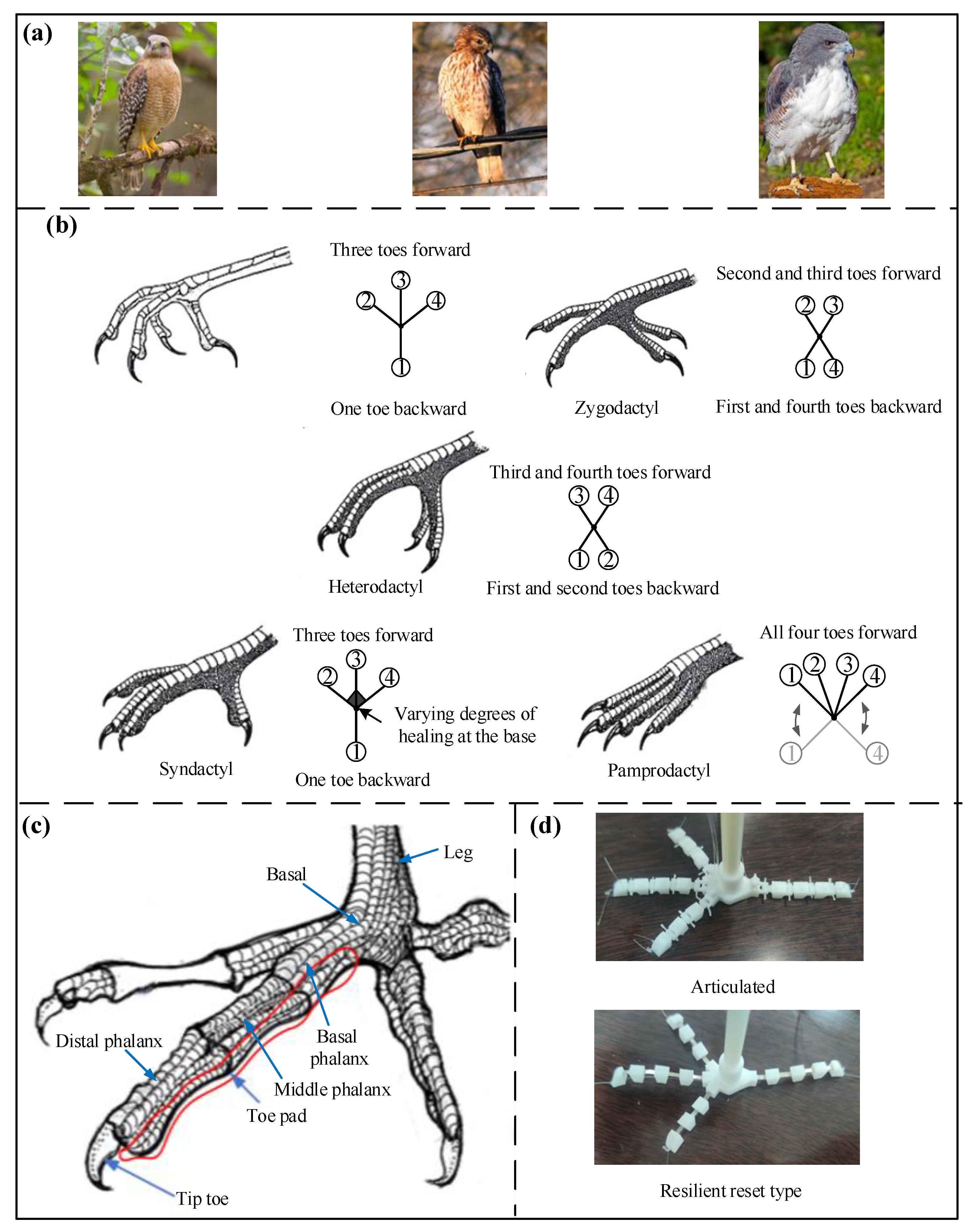
In response to the above problems, this paper proposes a new effective solution. Inspired by bird perching grasping, two kinds of bird-like claw perching grasping mechanism are designed, including the driving structure, leg structure and claw structure from top to bottom, which are divided into articulated type and elastic reset type according to the different compositions of the claw structure. The shape of the claws of the two types of perching grasping mechanism is “three in front and one at the back”, and two servos actively drive the fishing line to complete the claw toe grasp and release work, so there are no problems with limited perching time and difficult separation due to the sticky pad attachment method. Meanwhile, the use of two drivers, the overall small size and light weight effectively avoid the bulky traditional mechanical gripper. It can finally perch on branches, and the multi-degree-of-freedom claw toe has good adaptability to differently shaped objects, and can grasp objects of certain weight and grasp smoothly.
The imitation bird claw grasping mechanism studied in this paper can be installed in the fuselage of UAVs in the future to realize the transportation of aerial items of UAVs, and they can also perch and stay on tree branches to improve their range and perform special surveillance and search and rescue tasks. Of course, it is not limited to application to UAVs, but also has a wide range of practical application scenarios, improving the structure size as needed and adding auxiliary tools, such as robotic arms and cameras, to be applied in military, medical, aviation, intelligent industrial production and daily life scenarios, as robotic hands instead of humans to complete work with high-volume and high-quality requirements.
The paper is organized as follows:
Section 2 explains the structural design of the claw section of the bionic perching grasping mechanism and the actuation method inspired by the perching mechanism of birds in nature.
Section 3 designs the structural components of the two perching grasping mechanisms.
Section 4 analyzes the articulated claw toe rotation and grasping.
Section 5 describes physical experiments to verify the results of the claw toe rotation and grasping analysis and experiments on the grasping object shape adaptability and load capacity of the two perching grasping mechanisms for experimental analysis and comparison, and finally
Section 6 concludes the work of the paper and provides an outlook for future research.
3. Design of Two Perching and Grasping Mechanisms
3.1. Overall Structural Design
The overall structural design of the two perching grasping mechanisms is shown in
Figure 2a. The articulated perching grasping mechanism consists of a driving structure, a leg structure and a claw structure from top to bottom, with a through-hole connection between the driving structure and the leg structure, and between the leg structure and the claw structure. The difference between the resilient reset perch gripping mechanism and the articulated type lies mainly in the claw structure and the reset method.
3.2. Driving Structure
As shown in
Figure 2b, the driving structure includes a servo base plate, a servo, a driving pulley and a support seat. The rectangular section through-hole in the middle of the servo base plate can be nested and connected with the microlight fuselage, and the two through-holes on each side are for internal and external fishing lines to penetrate. The internal teeth in the middle of the driving pulley engage with the teeth of the output gear of the servo. The driving pulley has two slots of different radius sizes, facing the two through-holes in the servo base plate. As the output gear of the servo has a short reach, tightening of the internal and external fishing line will damage the driving pulley, so a support base is designed to support the driving pulley, which is fixed to the servo base.
The resilient repositioning perch gripping mechanism uses only the internal line to perform the grip, so theoretically the servo base plate only needs to be provided with a through-hole for the internal line to pass through and the pulley to be provided with a slide slot. To compare the gripping performance of the two mechanisms, the same servo driving structure is used.
3.3. Claw Structure
The articulated claw structure consists of a claw base, small pulley and four claw toes, as shown in
Figure 2a,c. The claw base is provided with a cylindrical tubular projection above the claw base for connection to the leg, surrounded by four projecting branches, the upper side of the branches is hinged to fit the toe bone, the lower through-hole is used to run through the fishing line, the interior is provided with four transitional circular through-holes to change the direction of the internal fishing line. The fishing line run through by the four branches converges at the cylindrical tubular projection above the claw base, the cross-section of the four branches at the root of the claw base is made sloping to allow the claw toe to produce a greater curvature. The bottom of the claw base is curved to better suit the object being grasped. The four small pulleys are connected by pins on the upper surface of the claw base and the external fishing line passes through the bottom of the small pulleys, changing the direction of the external line and reducing friction.
Among the four claw toes, there are two long claw toes in the middle and short claw toes on either side. The angle between the adjacent long and short claw toes is designed to be 55° without interfering with each other, and the long claw toe plays a more obvious gripping role. The clawed toe consists of toe bones and toe tips, with the long claw toe consisting of 3 toe bones and a toe tip, and the short claw toe consisting of 2 toe bones and a toe tip. The toe bones are designed in a trapezoidal shape, the sides of the base are rounded to create a greater angle of curvature between the adjacent parts of the claw toe. The toe bone has a rounded hole underneath for running the internal fishing line through, a protruding earring above for the external fishing line to run through and protruding parts on both sides for connecting adjacent parts. The toe tip is the end of the claw toe, with the same design of protruding earring above and the same design of the left end as the toe bone, with the difference that the fishing line below the through-hole runs in a smooth curve to reduce friction and avoid the toe tip bending upwards to a certain extent, and the end of the toe tip is designed as slender. The toe bone is hinged to the claw base, the toe bone to the toe bone and the toe bone to the toe tip, with the through-hole in the middle of the hinge fitted with a pin gap and the through-holes on both sides fitted with a pin interference, so that the toe bone can be rotated relative to the claw base, the back toe bone relative to the front toe bone and the toe tip relative to the toe bone.
As shown in
Figure 2a,d, the resilient reset jaw structure comprises a claw base and four claw toes. The recesses on the upper side of the four protruding branches of the claw base are used to embed the resilient connectors and the lower through-hole is used to allow the fishing line to penetrate. The rest of the structural features are the same as for the claw base of the articulated gripping mechanism. The claw toe includes three main parts: The long claw toe consists of 3 toe bones, 4 elastic connectors and 1 toe tip, the short claw toe consists of 2 toe bones, 3 elastic connectors and 1 toe tip. In order to make the experiment consistent, the number of toe bones and toe tips is the same for both gripping mechanisms; the elastic connectors are flexible and have a high recovery capacity from deformation and are embedded in the grooves of the claw base, toe bones and toe tips. Compared to the articulated ones, there are not protruding earrings above the toe bones and toe tips.
3.4. Tendon Arrangement
The tendon is a fishing line that runs through the entire perching and grasping mechanism. For the articulated perching and grasping mechanism, two fishing lines are used, divided into an external and an internal fishing line, where the external fishing line is exposed outside and runs through the earring above each component of the claw toe, through the claw toe, the small pulley, the servo base plate and the driving pulley. The internal fishing line runs through the through-hole set in the component, through the claw toe, the claw base, the leg structure, the servo base plate and the driving pulley. The internal line, which generates a large amount of displacement, is wound clockwise around the large-radius chute of the driving pulley, with the end point of the line tied to the wall of the chute and the other end point fixed at the toe tip. Meanwhile, the external line, which generates a small amount of displacement, is wound counter-clockwise around the small-radius chute, with the two end points of the line fixed in the same way as the internal line.
For the articulated gripping mechanism, when the claw toe gripping work is carried out, the claw toe is driven and controlled by servos. The servo is deflected counter-clockwise by a certain angle, and synchronously drives the driving pulley rotation, the fishing line wound on the two slots produce different displacement deformation, the internal fishing line is tightened and the external fishing line is loosened, so each claw toe is bent, completing the gripping work. Then, the servo stops deflection. In contrast, when the claw toe is extended, the servo is deflected clockwise by a certain angle and the driving pulley is driven to turn simultaneously, the internal line is released and the external line is tightened, so the claw toe is gradually extended from bending.
The elastic reset perch gripping mechanism uses a single line, which is distributed and fixed in the same way as the internal line of the articulated type. The drive control is the same as that of the articulated type, but the line is pulled tight during grasping, and the elastic connection is deformed by bending. Then, the claw toes grasp the object. While the line is released during extension, the elastic connection restores itself to deformation and finally the claw toes extend.
4. Claw Toe Rotation Gripping Analysis
4.1. Claw Toe Rotation Analysis
The parts of the claw toe have a certain limit range of rotation angle between them and, when greater than the angle constraint range, the parts will show collision interference. Specifically, the angle of rotation of the toe of the articulated perch gripping mechanism relative to the claw base ranges from 0 to 80.34°, the angle of rotation of the latter toe relative to the former toe ranges from 0 to 67.76° and the angle of rotation of the toe tip relative to the toe ranges from 0 to 68.26°.
When the claw toe is bent or extended, a certain amount of deformation of the fishing line occurs and, with reference to the range of angles of rotation between the parts of the claw toe, the deformation of the fishing line through the long and short claw toe is shown in
Table 1. When the long and short claw toes are bent from extension, the external line becomes longer and the internal line becomes shorter, and the internal line has approximately twice the amount of deformation as the external line. The design of the driving pulley groove radius is based on the relationship between the internal and external line deformation, so that the large groove radius is also approximately twice as large as the small groove radius.
In addition, the deformation of both the internal and external line of the long toe is greater than that of the short toe, and the difference between the deformation of the long and short toe is basically constant, with a difference of 1.25 mm for the external line and 2.03 mm for the internal line, the deformation of the long toe is used as a benchmark and the short toe is compensated for with a suitable spring according to the difference in deformation.
The theoretical relationship between the deflection of the line and the angle of deflection of the servo is as follows.
where
L is the amount of line deflection (mm),
n is the angle of deflection of the servo (°),
r is the radius of the driving pulley slots (mm), Δ
x is the spring compensation (mm).
The theoretical angle of the servo is 180°, but in practice the maximum operating angle is approximately 160°, which is within the normal operating range of the servo and can achieve the maximum deformation of the internal and external fishing line of the long claw toe. Based on Equation (1), the final radius of the driving pulley is 4.5 mm for the large slot and 2.3 mm for the small slot. r is 2.3 and Δx is 0 when calculating the external line deflection of the long claw toe, r is 4.5 and Δx is 0 when calculating the internal line deflection, r is 3 and Δx is 1.25 when calculating the external line deflection of the short claw toe, r is 4.5 and Δx is 2.03 when calculating the internal line deflection.
Using the long claw toe as an example, the articulated perch gripping mechanism achieves the maximum deformation results, as shown in
Figure 3.
4.2. Claw Toe Gripping Analysis
The articulated perch gripping mechanism was made to grip columnar objects in the diameter range 15–60 mm with a diameter interval of 5 mm and the long claw toe gripping results are shown in
Figure 4.
As can be seen from
Figure 4, on the one hand, with the increase in the grasping diameter, the degree of bending deformation of the claw toe gradually decreases, and the deformation of the fishing line becomes smaller and smaller; on the other hand, with the increase in the grasping diameter, the envelope angle becomes smaller and smaller. When the diameter is 15 mm and 20 mm, the claw toe can completely envelop the object and leave a residual length, the envelope angle is greater than 360° and the two long claw toe tips appear to interfere with the collision. When the diameter is 25–50 mm, the claw toe can envelop at least 1/2 of the circumference of the object, and the envelope angle is greater than 180°. When the diameter is 55 and 60 mm, the claw toe envelope length is less than 1/2 of the circumference of the object and the envelope angle is less than 180°.
In addition, as the gripping diameter increases, the contact surface between the toe bone and the base of the toe tip and the object becomes larger, which is more stable for gripping. At a gripping radius of 15 mm, only the toe tip touches the object, at a gripping radius of 20 mm, the toe tip and one toe bone touch the object, at a gripping radius of 25–45 mm, the toe tip and two toe bones touch the object and the third toe bone has an increasing contact surface with the object, at a gripping radius of 50–60 mm, the toe tip and three toe bones touch the object, which means that the long claw toe is in close proximity to the object.
As there is a correspondence between the amount of deformation of the external and internal fishing line of the long claw toe, the deformation of the internal fishing line of the long claw toe was used as the measurement standard and a total of 10 sets of data were obtained as shown in
Table 2.
d indicates the diameter of the object,
S indicates the length of the internal fishing line of the long claw toe after deformation,
L indicates the amount of deformation of the internal fishing line of the long claw toe and
N indicates the envelope angle (the angle of the center of the circle corresponding to the envelope arc formed by the claw toe when grasping the object).
The amount of deformation
L is known and the corresponding rotation angle
n of the servo can be calculated by Equation (1). A quadratic polynomial fit is made to the amount of line deformation
L and the rotation angle
n of the servo corresponding to the gripping of 15–60 mm diameter objects, and a cubic polynomial fit is made to the envelope centroid angle
N. The results are shown in
Figure 5. It can be seen that as the gripping diameter increases,
L,
n and
N gradually decrease and to an increasingly lesser extent.
When the claw toe grips an object, the claw toe is in contact with the surface of the object and the gripping force of the claw toe on the object is generated by the rudder and transmitted by the line. Theoretically, the greater the weight of the object, the greater the gripping force required, i.e., the greater the force exerted by the line on the lower surface of the line holes in each part of the claw toe, which can easily cause damage to the claw toe. A simplified model was established, with the claw toe in contact with the surface of the object, the finger bones on the upper side of the claw toe articulated with restraint and a force of 5 N applied to the lower surface of the fishing line hole in the direction perpendicular to the toe bone and toe tip. The stress and displacement results are shown in
Figure 6, the maximum stress 9.742 × 10
5 N/m
2 and the maximum displacement 4.465 × 10
−4 mm are at the fishtail hole, and the stresses and displacements decrease from the root of the toe to the toe fishtail hole. While the allowable stress of plastic ABS material is 24.5 MPa, the maximum stress in the claw toe is much less than the permissible stress, and the displacement of the claw toe is very small, which shows that the claw toe structure has sufficient resistance to deformation.
5. Physical Experiment Analysis
5.1. Physical Assembly and Experiment Platform Construction
The wire diameter of the pin used in the articulated perch gripping mechanism is 0.7 mm, and the elastic connection of the elastic reset perch gripping mechanism is selected as 0.1 mm 301 stainless steel shrapnel. The weight of the two grasping mechanisms is about 15 g, the claw structure is about 3.5 g, the long claw toe is about 3 cm long and the short claw toe is about 2.5 cm. A 9 g drive servo is chosen according to the rotation angle of the servo required for the grasping work and to meet the requirements of the grasping driving force. A 0.2 mm fishing wire is chosen as the transmission medium of the grasping force for the tendon, because of its toughness, strong tensile capacity and low friction resistance between the parts. A 3D printed resin material was used.
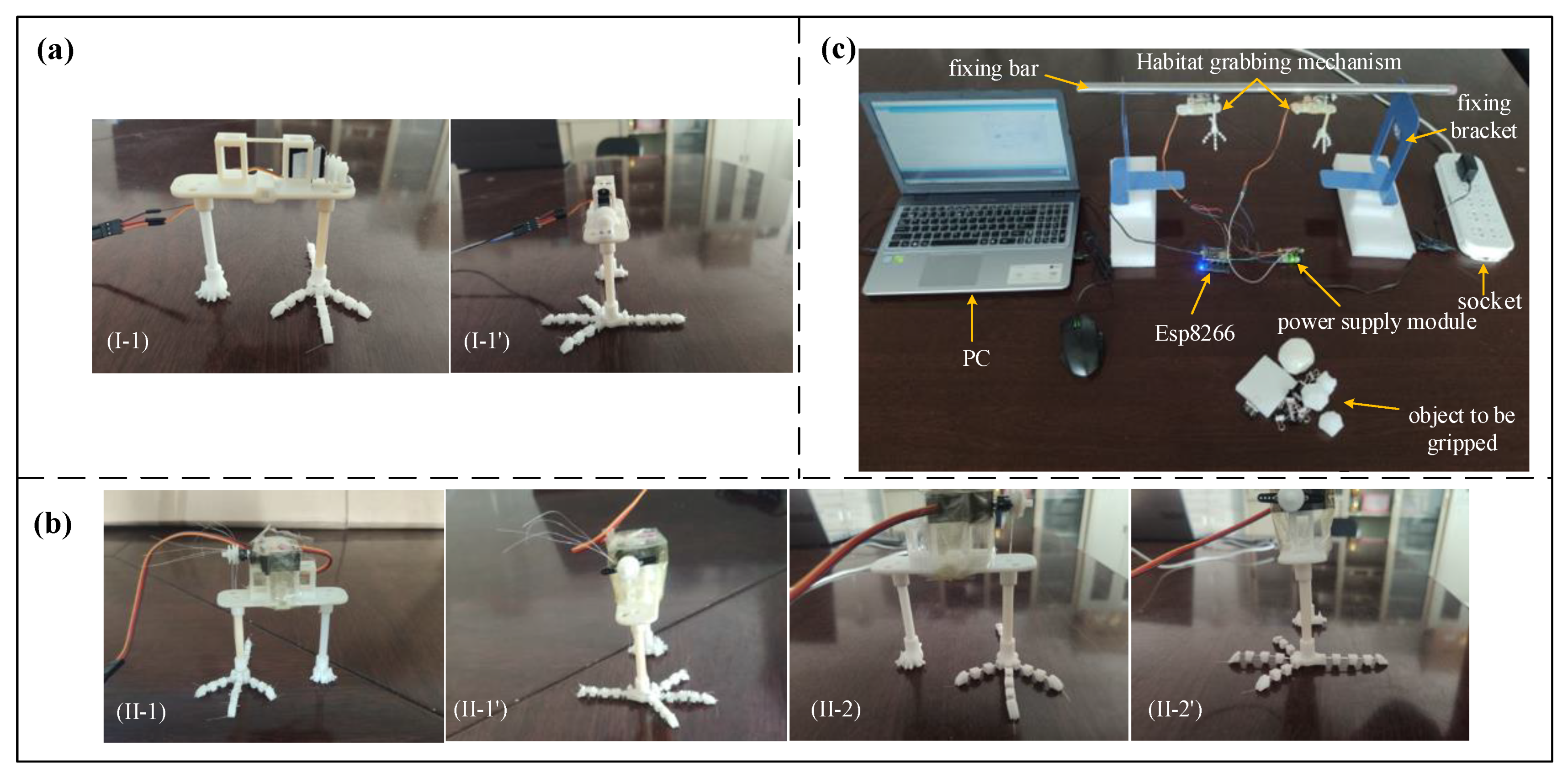
One side of the gripping mechanism was assembled, as shown in
Figure 7a. In order to make the gripping structure lighter, the servo type chosen for the first experiment scheme was 2.7 g, but the experiment results showed that the driving torque of the servo was too small, so the servo for the second time was chosen to be 9 g for both habitat gripping mechanisms. The servo was fixed directly to the servo base plate, with the slots facing the holes in the servo base plate. The final assembly of the two perch gripping mechanisms is shown in
Figure 7b.
As shown in
Figure 7c, the hardware of the experiment platform mainly includes a PC, socket, power supply module, Esp8266, fixing bar, fixing bracket and grasped object, and the software includes Arduino and LabView. After the voltage is reduced to 5 V by the power supply module, the pins of the power module supply power and ground to the servo through the connection line, the signal line of the servo is connected to the pins of the microcontroller Esp8266, the other end of the data line of the microcontroller Esp8266 is connected to the USB port of the PC. The two kinds of perching and grasping mechanism and the fixing bar are fixed together, and the fixing bar is attached to the fixing bracket.
5.2. Experimental Verification
Performance experiments were carried out for two different perch gripping mechanisms, firstly to verify the claw toe bending deformation capacity of the two perch gripping mechanisms under no-load conditions, as shown in
Figure 8.
The maximum relative rotation angle between the individual parts of the articulated claw toe is consistent with the results of the previous analysis of claw toe rotation. When the claw toe reaches its maximum degree of bending, the articulated servo rotation angle is approximately 158°, which should theoretically be 156.86°, almost reaching the result of the maximum deformation of the fishing line analyzed earlier. The articulated type has a stronger degree of bending deformation compared to the elastically resettable type, but the curve formed after bending is not as smooth as the elastically resettable type.
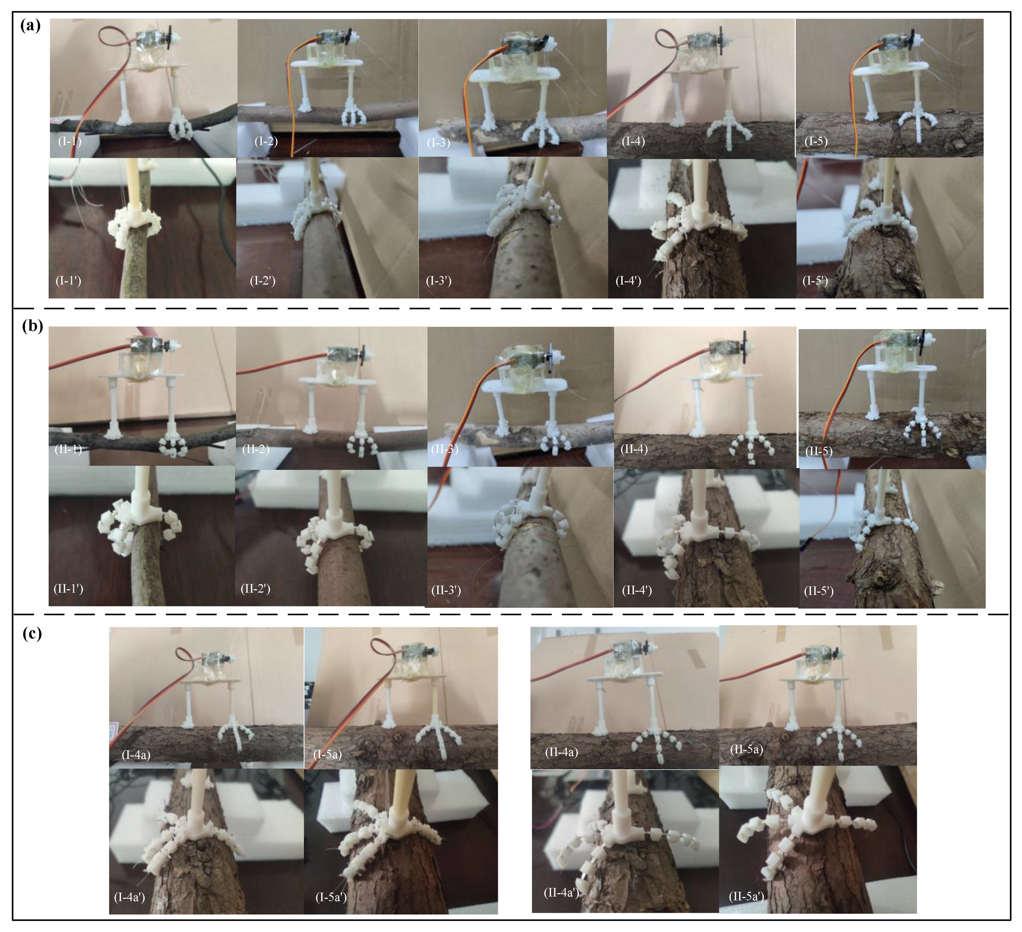
The claw toe grip results were verified for columnar objects. As the vehicle commonly grips tree branches for perching, tree branches were chosen for the grip experiment in order to make the experiment results more convincing (
Video S1). As shown in
Figure 9a, the experiment results show that the articulated ones can successfully grasp branches with diameters of 12.5 mm, 21.5 mm, 27.4 mm, 48.6 mm and 55.8 mm, corresponding to servo rotation angles of 145°, 122°, 101°, 60° and 50°, which is approximately twice the result of the
n-curve fit, due to the fact that, while ensuring that the branches are wrapped as far as possible, sufficient gripping force is required, thus requiring the servo to rotate further. Both gripping mechanisms can be clearly seen in the side gripping diagrams, where the contact area between the base of the claw toe and the branch becomes larger and the envelope angle becomes smaller as the diameter increases. However, when grasping larger diameter branches of 48.6 mm and 55.8 mm, as shown in
Figure 9c, both grasping mechanisms can successfully stand on the branch as the contact area between the base of the claw seat and the top of the branch is sufficiently large. However, in practice, taking into account the natural environment, grasping is also required if the perch is stable, and the grasping results show that the toe bones arch upwards extremely easily and the toe tips play an increasingly prominent role, snapping hard against the surface of the branch.
Compared to the two perch gripping mechanisms, firstly, the resilient reset type does not successfully grip 12.5 mm branches, thus the articulated type has a greater gripping range when gripping branches of different diameters. Secondly, after several gripping experiments, the resilient reset type showed plastic deformation of the elastic joint, which does not fully return to its extended state and will suffer from elastic depletion in long-term use, while the articulated type does not show any effect. Again, when gripping branches of the same diameter, the servo deflection angle required for the resilient repositioning type is greater than that of the articulated type. Finally, the articulated type is not as soft in terms of the flexing effect of the claw toe as the resilient repositioning type.
5.3. Adaptability and Load Capacity Experiment Analysis
To assess the adaptability of the two perching grasping mechanisms for grasping different types of objects, rectangular cardboard and rectangular, spherical and irregularly shaped foam were selected for performance experiments (
Video S1), and the grasping results are shown in
Figure 10. The results show that both perch gripping mechanisms have good passive bending deformation capability of the claw toes and both can adapt to the experiment object. Specifically, the cardboard was thin and had a smooth surface, and the initial experiments were conducted with a narrow surface as the contact surface, which resulted in a failed grip, mainly due to the small contact area between the bottom surface of the claw structure and the cardboard, the smooth surface of the object and the object’s own gravity causing a large relative slip, so a wide surface was chosen as the contact surface instead and a successful grip was achieved. The two gripping mechanisms can easily grip rectangular foam objects with a large contact area and high friction with the foam material, resulting in less relative sliding. The irregular foam object is thick and has a certain slope on the sides, and the contact area of the two gripping mechanisms is very small when gripping, but the four toe tips can be embedded or hooked into the object, which is the key reason for successful gripping. Gripping near spherical objects is easiest, and both types of gripping mechanism have a large contact area between the base of the toe and the object, and have a good envelope for a stable grip.
Therefore, the two perching grasping mechanisms have good adaptability, increasing for cardboard, irregular foam objects, rectangular foam objects and spherical foam objects, in that order. However, the success of the grasp also depends on the point of impact of the grasp, which is theoretically the center of gravity of the object, but in practice tends to make regular grasped objects balanced and symmetrical with respect to both sides of the claw structure. For irregularly shaped and different types of objects, it is particularly important to select the correct contact surface, increase the contact area and give full play to the toe tip.
On the one hand, a standard counterweight carrier is required for the gradual application of forces to the jaw structure of the perching grasping mechanism and, on the other hand, inspired by the different adaptability of the perching grasping mechanism to different objects, two options are proposed for experimenting with the load performance of the two types of perching grasping mechanisms, and a rectangular foam object and a spherical foam object are chosen as counterweight bases, which are counterweighted with clamps and large head pins on the foam object, as shown in
Figure 11. The experiment results show that if the rectangular foam object is chosen as the counterweight base, the final maximum applied load force is 0.0435 N for the articulated type and 0.1457 N for the resilient reset type and, if the spherical foam object is chosen as the counterweight base, the final maximum load force is 0.2497 N for the articulated type and 0.4487 N for the resilient reset type, which is about three times the overall weight of the grasping mechanism and about 13 times the weight of the claw structure. Both perching grasping mechanisms were able to restore the claw toe to its original state even after releasing the object, and neither the object nor the claw toe was damaged. It can be seen that the load capacity of the two types of perch gripping mechanism is indeed related to the counterweight base. With the same counterweight base, the resilient reset perch gripping mechanism can withstand approximately twice the load force of the articulated type. As the applied load mass increases, the duration of sustained grip decreases, even though the claw toes can still grip.
6. Conclusions
This paper proposes two new flexible perching grasping mechanisms inspired by a bird’s claw, with a unique shape design of “three in front and one at the back” and multiple degrees of freedom of the claw toe, simple structure and stable grasping. At the same time, the gripping mechanism is driven by two servos, and the fishing line transmits the gripping force, and the speed and gripping force of the servos for the object are controllable. After proposing the mechanical structure design scheme, the articulated perch gripping mechanism claw toe rotation gripping is analyzed, the analysis results are verified through experiments and the adaptability and load-bearing capacity of the two perch gripping mechanisms on objects of different shapes and sizes are tested. The maximum relative rotation angle between the parts of the articulated claw toe under no-load condition was consistent with the results of the claw toe rotation analysis, and the maximum deformation of the fishing line analyzed was almost reached when the claw toe reached the maximum degree of bending. The actual rotation angle of the rudder is about twice the result of the theoretical curve fitting because the claw toe needs sufficient gripping force while ensuring that it wraps around the branch as much as possible. The contact area between the base of the claw toe and the branch becomes larger and the envelope angle becomes smaller as the branch diameter increases for both perching grasping mechanisms. The claw toes of the two perching grasping mechanisms have good passive bending deformation ability and can grasp different types of objects, the toe tips play an important grasping role and the maximum object weight that the elastic reset type can grasp is about three times of its own weight. This imitation bird claw grasping mechanism effectively avoids the use of sticky pad adsorption, perching for a limited time and difficulty in separating the problem, the problems of limited perching time and easy separation that exist with the sticky pad attachment method. compared to the traditional imitation manual robotic perching grasping, and has obvious weight advantage and stable grasp and will not damage the object.
In comparison, the two types of perch gripping mechanism have their own advantages and disadvantages. The articulated type has a stronger degree of bending deformation, grips a larger range of branch diameters and, when gripping branches of the same diameter, the required servo deflection angle is greater for the resilient reset type than for the articulated type. After several gripping experiments, the resilient reset type has plastic deformation of the elastic joint, while the articulated type has no effect. However, the articulated version does not have as smooth and supple a toe bend curve as the resilient repositioning version, and has a significantly greater load capacity than the articulated version. In future research, the structural design of the articulated type will be improved so that the toe bending curve is smoother, and the elastic joint of the resilient repositioning type will be made of a material that is more elastic, more capable of self-recovery from deformation and requires less driving force during deformation and bending. The size of the model of the perching and grasping mechanism can be changed according to the actual needs, and it will be installed in the body of a microlight to improve the range in the future.


