
Vibration Analysis and Active Control of Rotor Shaft in Magnetically Suspended Air-Blower


Abstract
:1. Introduction
- (1)
- The vibration models of the magnetically suspended air-blower with unbalance terms were developed, and the current model of AMB-rotor shaft with unbalance vibration was established.
- (2)
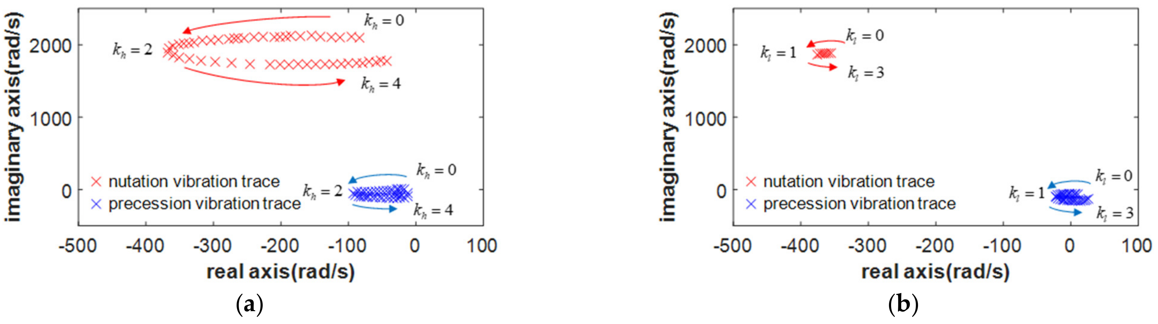
- The complex-field cross-feedback control model was designed to suppress the nutation and precession vibration of magnetically suspended air-blower.
- (3)
- The vibration analysis was critical to structure design and the active control high-speed rotor suspended by the magnetic forces, and it was fundamental to the vibration control of the air-blower using magnetic forces.
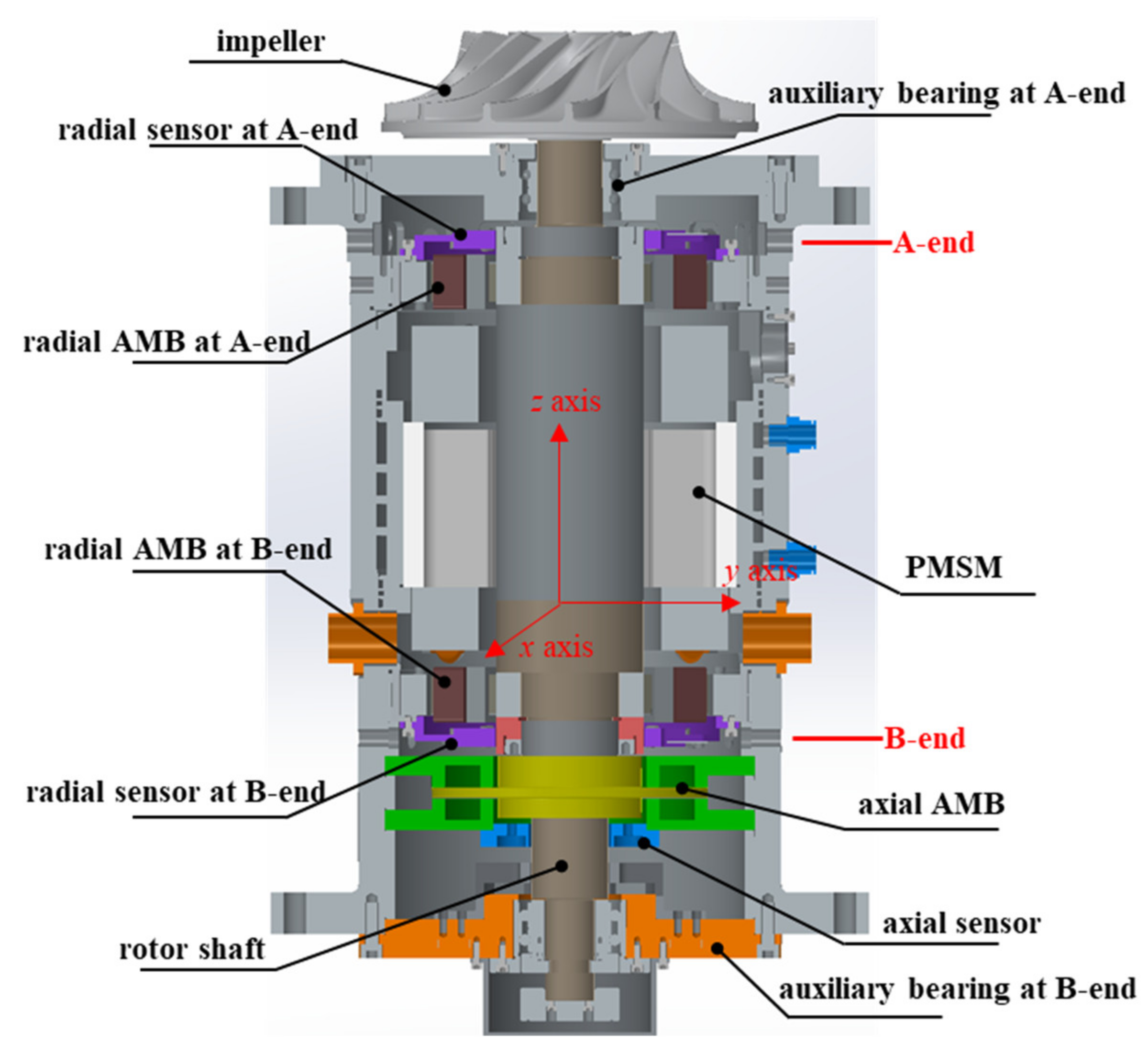
2. Structure of Magnetically Suspended Air-Blower
2.1. The Prototype of Magnetically Suspended Air-Blower
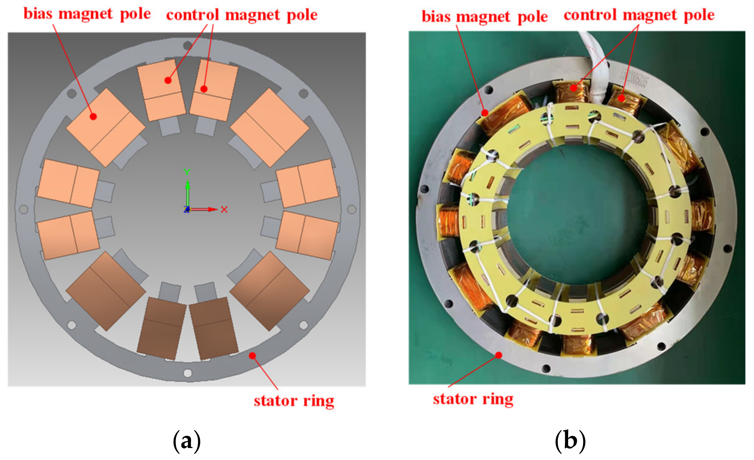
2.2. The Force Modeling of Radial AMB
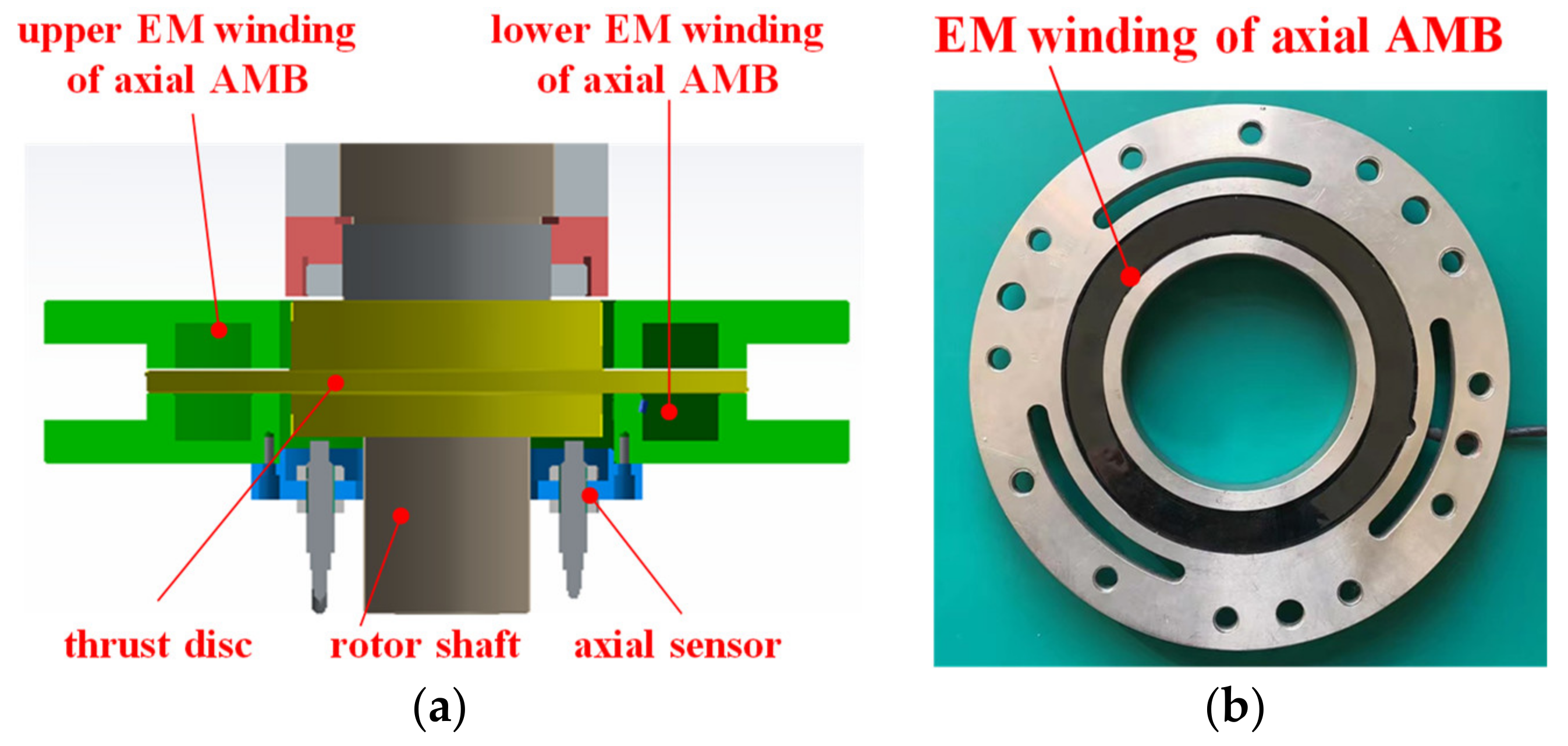
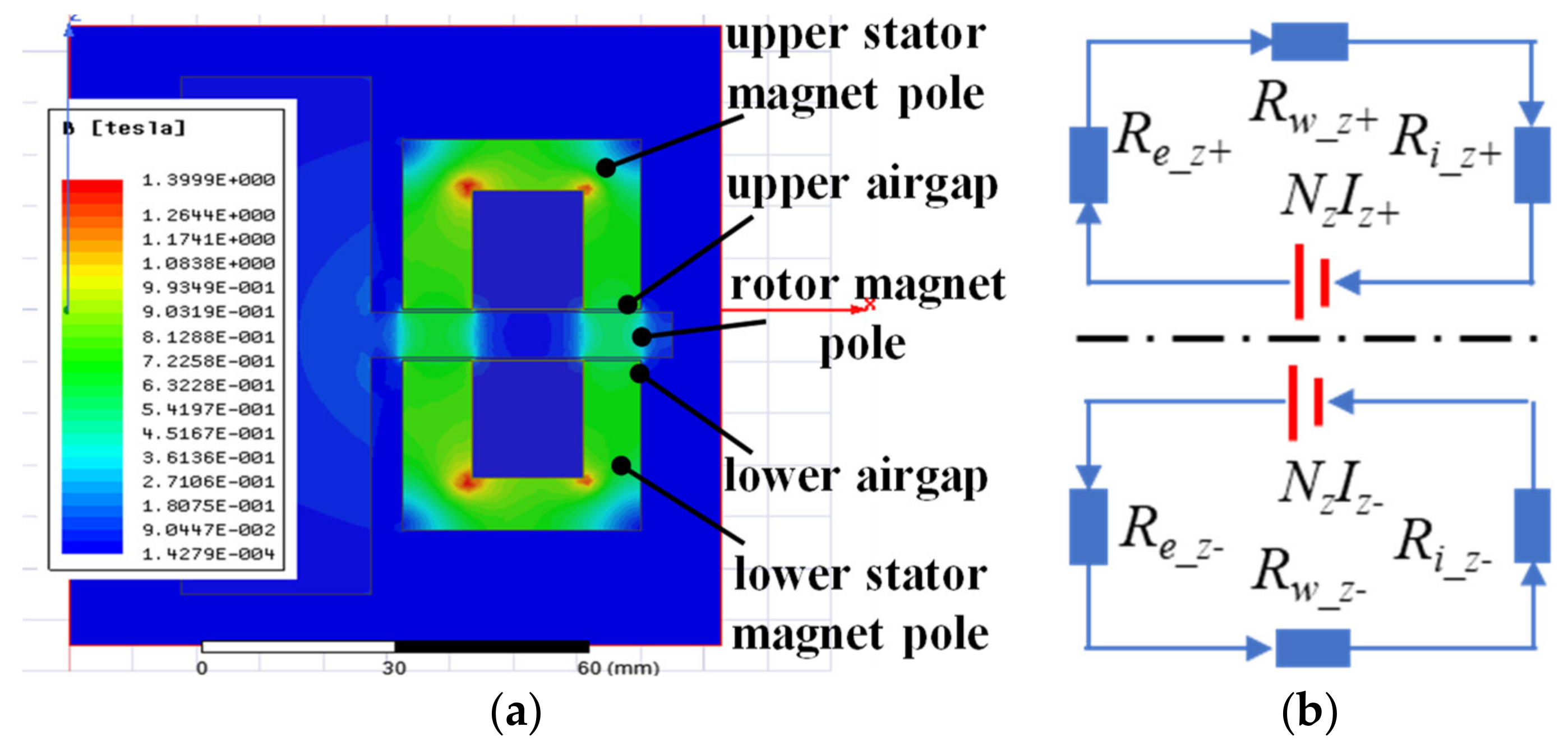
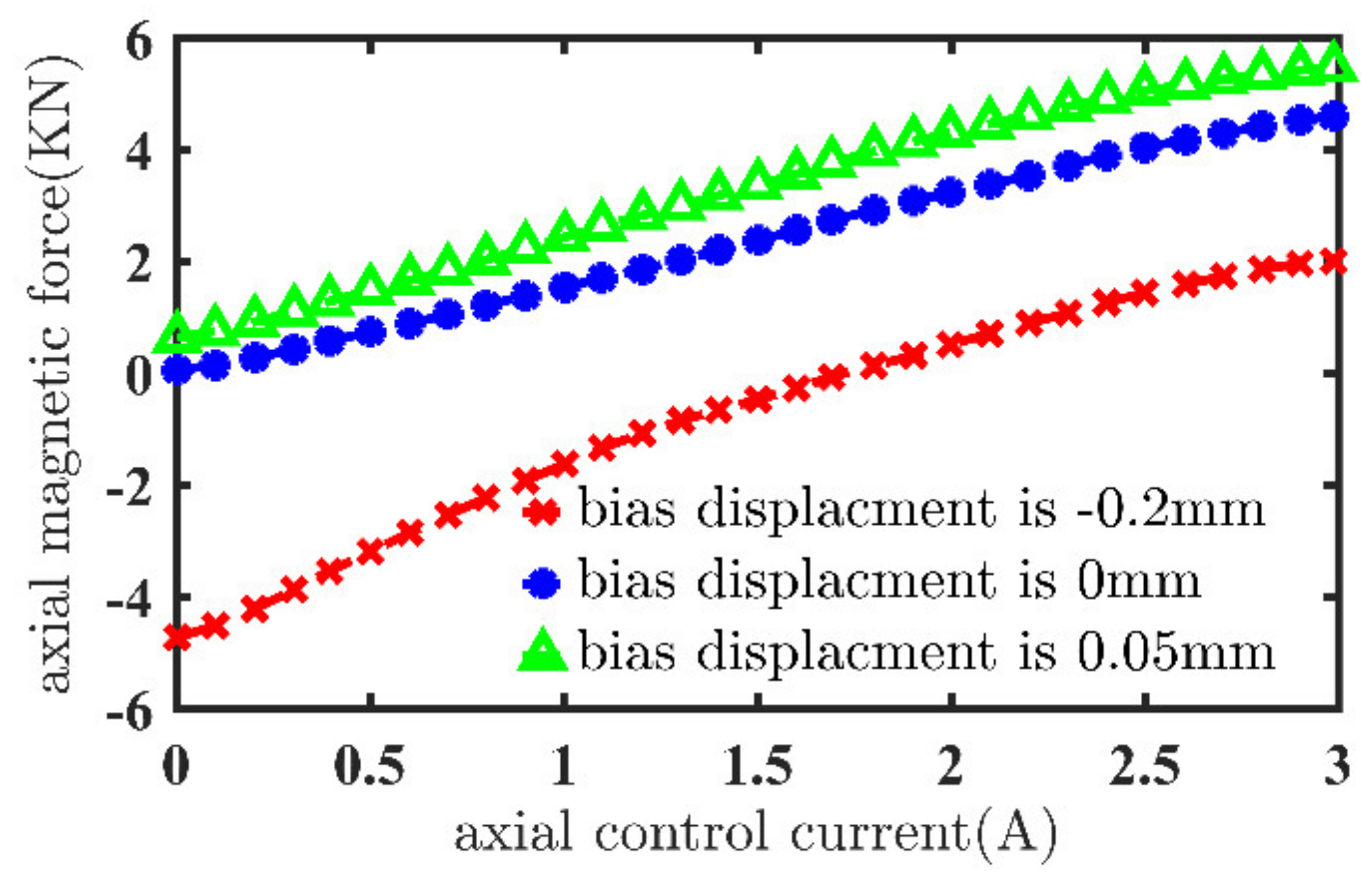
2.3. The Force Modeling of Axial AMB
3. Modeling of Rotor Shaft in Magnetically Suspended Air-Blower
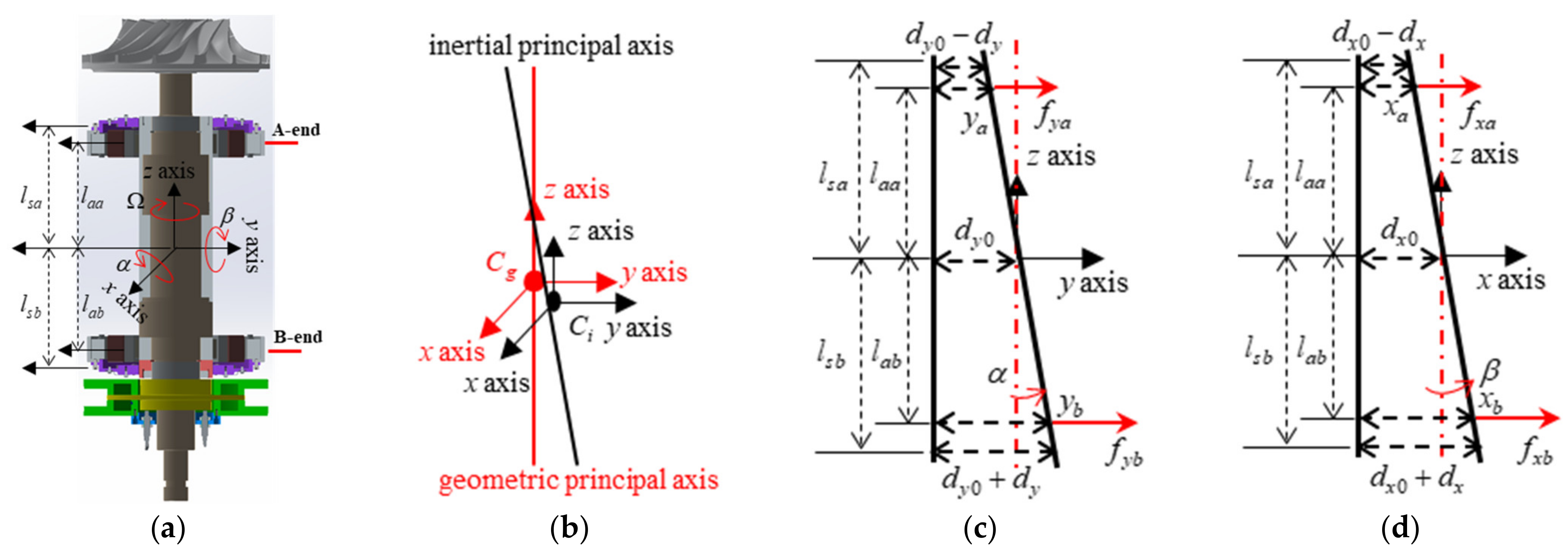
3.1. Force Model of Rotor Shaft with Unbalance Terms
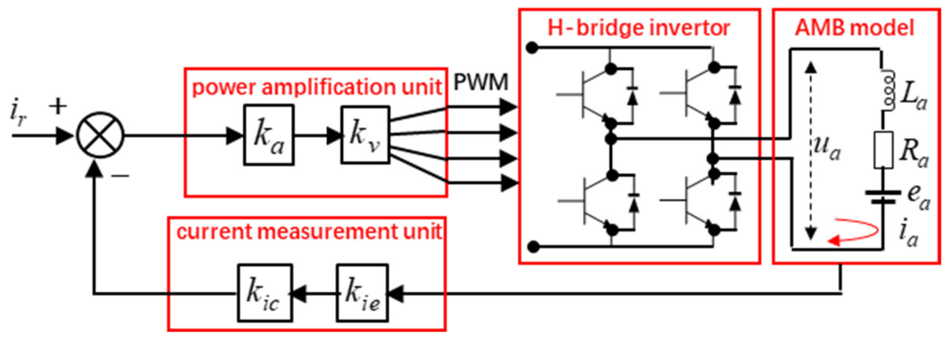
3.2. Current Model of Rotor Shaft with Unbalance Terms
3.3. Vibration Model of Rotor Shaft with Unbalance Terms
4. Complex-Field Cross-Feedback Control of Magnetically Suspended Air-Blower
- (1)
- The vibration force and torque caused by the unbalance terms of the rotor shaft having the same frequency as the rotating frequency.
- (2)
- The unbalance vibration forces in the radial direction are decoupling, but the unbalance vibration torques are coupling in the radial direction.
- (3)
- The coefficients kh and kl could suppress the nutation and precession vibration of the rotor shaft decoupling.
5. The Experimental Verification
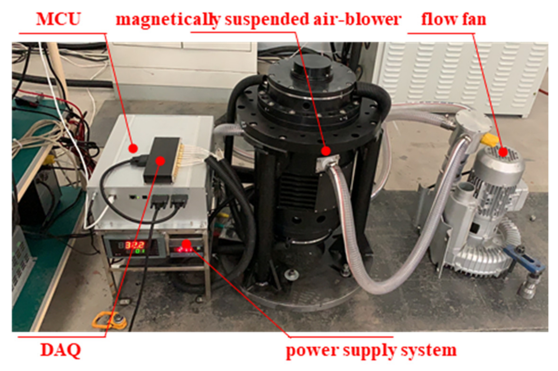
5.1. Experimental System of Magnetically Suspended Air-Blower
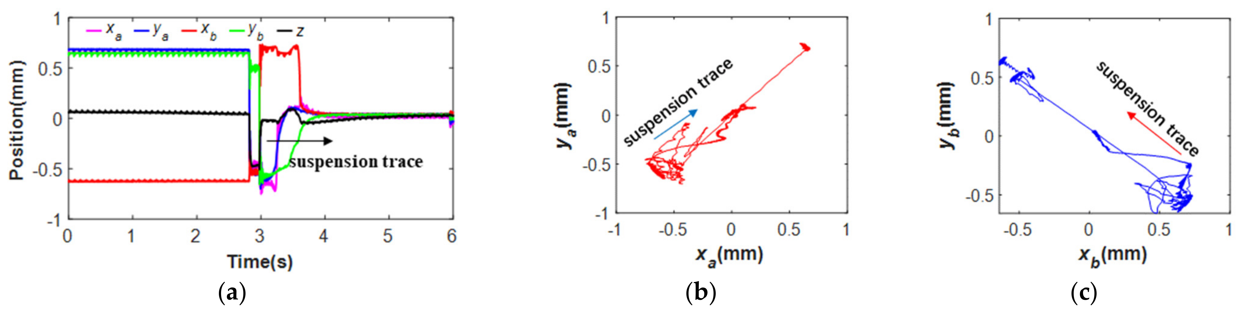
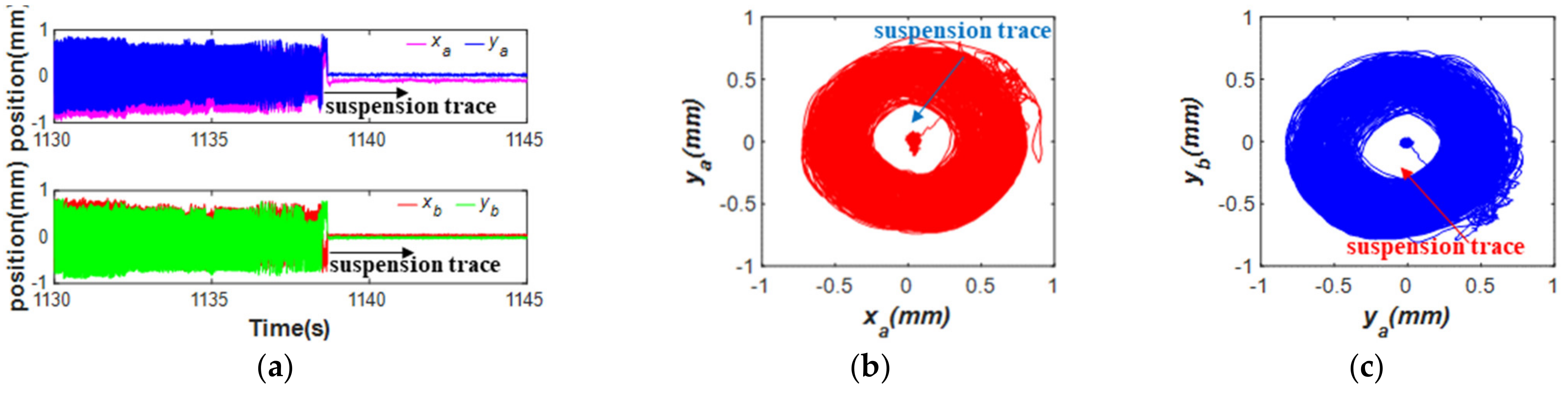
5.2. Rotor Trajectory of Magnetically Suspended Air-Blower
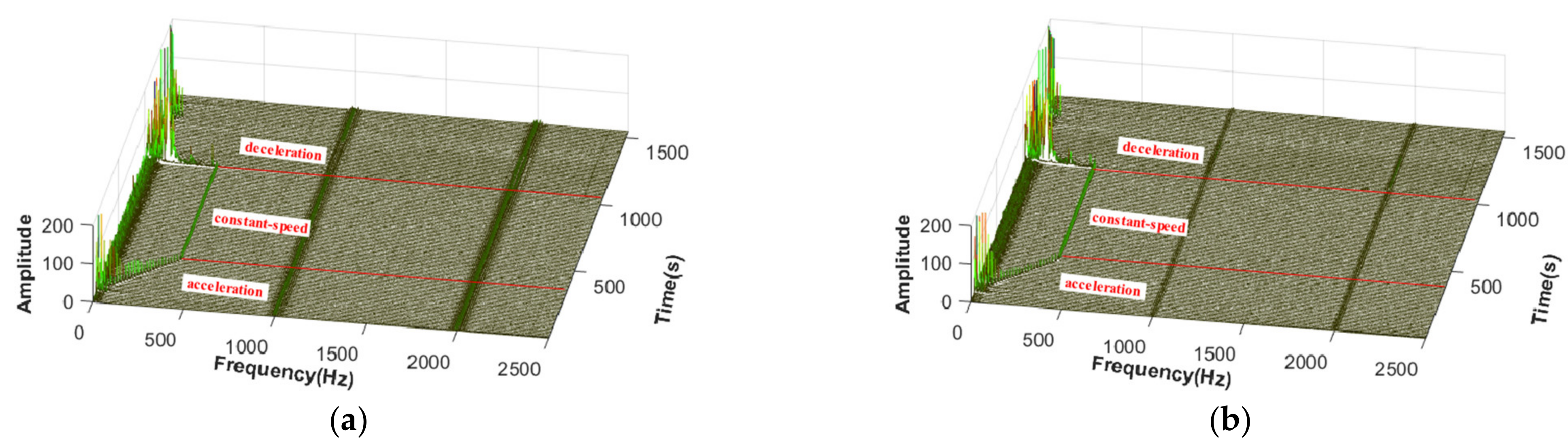
5.3. Vibration Characteristics of Magnetically Suspended Air-Blower
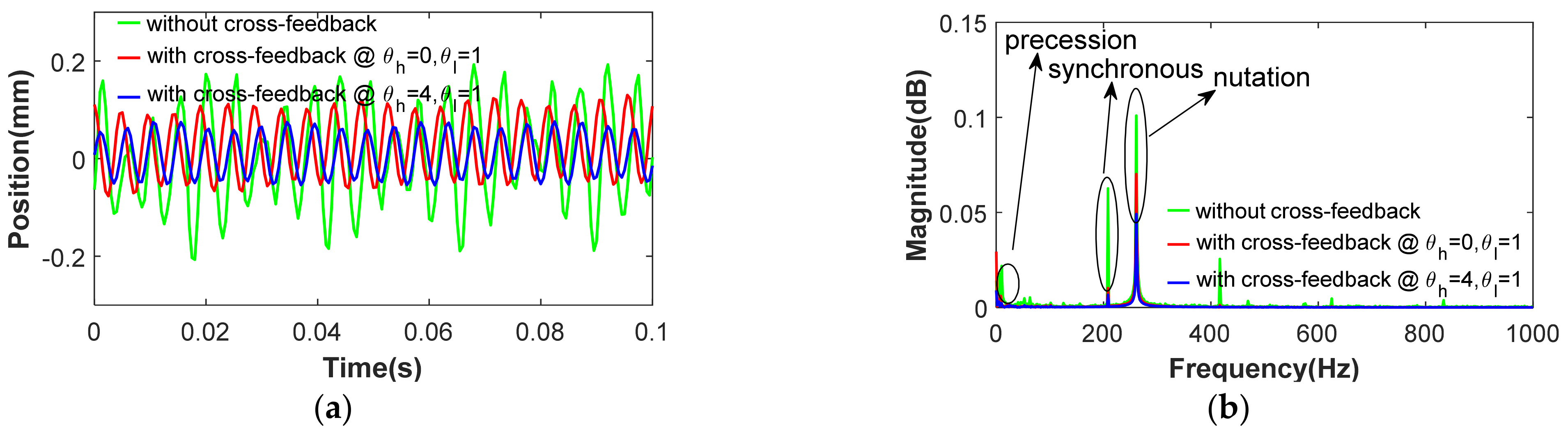
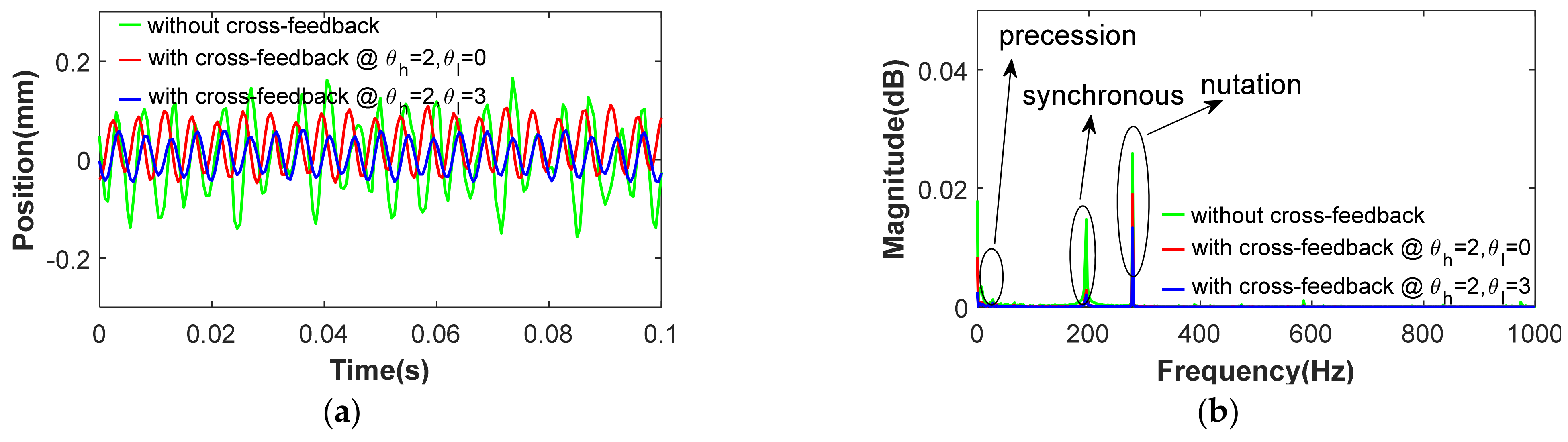
5.4. Cross-Feedback Control of Magnetically Suspended Air-Blower
6. Conclusions
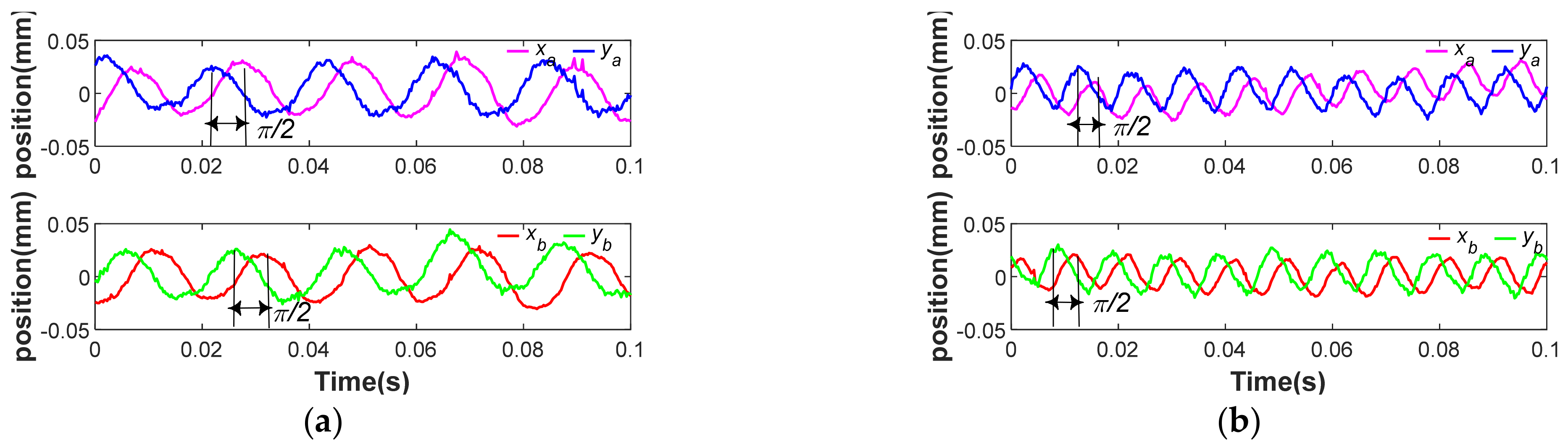
- (1)
- The displacement trajectory of the rotor shaft in x axis had the phase difference to the displacement in y axis.
- (2)
- The vibration amplitude of rotor shaft in the magnetically suspended air-blower was affected by rotating speed.
- (3)
- The complex-field cross-feedback control model was useful to suppress the vibration amplitudes of the magnetically suspended air-blower, and the high frequency damping coefficient could effectively mitigate the nutation and precession vibration.
Author Contributions
Funding
Data Availability Statement
Conflicts of Interest
References
- Smirnov, A.; Uzhegov, N.; Sillanpää, T.; Pyrhönen, J.; Pyrhönen, O. High-speed electrical machine with active magnetic bearing system optimization. IEEE Trans. Ind. Electron. 2017, 64, 9876–9885. [Google Scholar] [CrossRef] [Green Version]
- Samanta, P.; Hirani, H. Magnetic Bearing Configurations: Theoretical and Experimental Studies. IEEE Trans. Magn. 2008, 44, 292–300. [Google Scholar] [CrossRef]
- Hutterer, M.; Wimmer, D.; Schrödl, M. Control of magnetically levitated rotors using stabilizing effects of gyroscopes. Mech. Syst. Signal Process. 2021, 166, 108431. [Google Scholar] [CrossRef]
- Ahrens, M.; Kucera, L.; Larsonneur, R. Performance of a magnetically suspended flywheel energy storage device. IEEE Trans. Control Syst. Technol. 1996, 4, 494–502. [Google Scholar] [CrossRef]
- Xiang, B.; Wang, X.; Wong, W.O. Process control of charging and discharging of magnetically suspended flywheel energy storage system. J. Energy Storage 2021, 47, 103629. [Google Scholar] [CrossRef]
- Li, X.; Palazzolo, A. A review of flywheel energy storage systems: State of the art and opportunities. J. Energy Storage 2021, 46, 103576. [Google Scholar] [CrossRef]
- Liu, Z.; Chiba, A.; Irino, Y.; Nakazawa, Y. Optimum Pole Number Combination of a Buried Permanent Magnet Bearingless Motor and Test Results at an Output of 60 kW With a Speed of 37000 r/min. IEEE Open J. Ind. Appl. 2020, 1, 33–41. [Google Scholar] [CrossRef]
- Rubio, G.C.; Fujii, Y.; Chiba, A. A Bearingless Motor with Passive Electrodynamic Suspension in Axial Direction. IEEE Trans. Ind. Appl. 2021, 57, 6812–6822. [Google Scholar] [CrossRef]
- Hutterer, M.; Wimmer, D.; Schrödl, M. Stabilization of a magnetically levitated rotor in the case of a defective radial actuator. IEEE/ASME Trans. Mechatron. 2020, 25, 2599–2609. [Google Scholar] [CrossRef]
- Peng, C.; Zhu, M.; Wang, K.; Ren, Y.; Deng, Z. A Two-Stage Synchronous Vibration Control for Magnetically Suspended Rotor System in the Full Speed Range. IEEE Trans. Ind. Electron. 2019, 67, 480–489. [Google Scholar] [CrossRef]
- Soni, T.; Dutt, J.K.; Das, A.S. Dynamic behavior and stability of energy efficient electro-magnetic suspension of rotors involving time delay. Energy 2021, 231, 120906. [Google Scholar] [CrossRef]
- Circosta, S.; Bonfitto, A.; Lusty, C.; Keogh, P.; Amati, N.; Tonoli, A. Analysis of a Shaftless Semi-Hard Magnetic Material Flywheel on Radial Hysteresis Self-Bearing Drives. Actuators 2018, 7, 87. [Google Scholar] [CrossRef] [Green Version]
- Xiang, B.; Wen, T.; Liu, Z. Vibration analysis, measurement and balancing of flywheel rotor suspended by active magnetic bearing. Measurement 2022, 197, 111305. [Google Scholar] [CrossRef]
- Dagnaes-Hansen, N.A.; Santos, I.F. Magnetically suspended flywheel in gimbal mount - Test bench design and experimental validation. J. Sound Vib. 2019, 448, 197–210. [Google Scholar] [CrossRef]
- Gallego, G.B.; Rossini, L.; Achtnich, T.; Araujo, D.M.; Perriard, Y. Novel Generalized Notch Filter for Harmonic Vibration Suppression in Magnetic Bearing Systems. IEEE Trans. Ind. Appl. 2021, 57, 6977–6987. [Google Scholar] [CrossRef]
- Sugimoto, H.; Miyoshi, M.; Chiba, A. Axial vibration suppression by field flux regulation in two-axis actively positioned permanent magnet bearingless motors with axial position estimation. IEEE Trans. Ind. Appl. 2017, 54, 1264–1272. [Google Scholar] [CrossRef]
- Lusty, C.; Keogh, P. Active Vibration Control of a Flexible Rotor by Flexibly Mounted Internal-Stator Magnetic Actuators. IEEE/ASME Trans. Mechatron. 2018, 23, 2870–2880. [Google Scholar] [CrossRef]
- Gong, L.; Zhu, C. Synchronous vibration control for magnetically suspended rotor system using a variable angle compensation algorithm. IEEE Trans. Ind. Electron. 2020, 68, 6547–6559. [Google Scholar] [CrossRef]
- Li, J.; Liu, G.; Cui, P.; Zheng, S.; Chen, Q. Synchronous Vibration Suppression of Magnetically Suspended Rotor System Using Improved Adaptive Frequency Estimation. IEEE Sens. J. 2020, 20, 11212–11220. [Google Scholar] [CrossRef]
- Yaseen, H.M.S.; Siffat, S.A.; Ahmad, I.; Malik, A.S. Nonlinear adaptive control of magnetic levitation system using terminal sliding mode and integral backstepping sliding mode controllers. ISA Trans. 2021, 126, 121–133. [Google Scholar] [CrossRef]
- Peng, C.; He, J.; Zhu, M.; Deng, Z.; Zhen, Z.; Liu, Q. Optimal synchronous vibration control for magnetically suspended centrifugal compressor. Mech. Syst. Signal Process. 2019, 132, 776–789. [Google Scholar] [CrossRef]
- Kim, C.-H.; Kim, K.-J.; Yu, J.-S.; Cho, H.-W. Dynamic Performance Evaluation of 5-DOF Magnetic Levitation and Guidance Device by Using Equivalent Magnetic Circuit Model. IEEE Trans. Magn. 2013, 49, 4156–4159. [Google Scholar] [CrossRef]
- Ferreira, J.M.; Anacleto, J. The magnetic field circulation counterpart to Biot-Savart’s law. Eur. Phys. J. Plus 2018, 133, 234. [Google Scholar] [CrossRef]
- Rosinová, D.; Hypiusová, M. Comparison of Nonlinear and Linear Controllers for Magnetic Levitation System. Appl. Sci. 2021, 11, 7795. [Google Scholar] [CrossRef]
- Fang, J.; Xu, X.; Tang, J.; Liu, H. Adaptive complete suppression of imbalance vibration in AMB systems using gain phase modifier. J. Sound Vib. 2013, 332, 6203–6215. [Google Scholar] [CrossRef]


| Symbol | Quantity | Value |
|---|---|---|
| m | mass of rotor shaft | 26 kg |
| Jx | equatorial moment of inertia | 0.13 kgm2 |
| Jz | polar moment of inertia | 0.06 kgm2 |
| Ω | rotational speed | 12,000 rpm |
| ksx | sensitivity of sensor | 9 V/mm |
| kwx | amplification coefficient | 0.2 A/V |
Publisher’s Note: MDPI stays neutral with regard to jurisdictional claims in published maps and institutional affiliations. |
© 2022 by the authors. Licensee MDPI, Basel, Switzerland. This article is an open access article distributed under the terms and conditions of the Creative Commons Attribution (CC BY) license (https://creativecommons.org/licenses/by/4.0/).
Share and Cite
Zheng, L.; Nie, W.; Xiang, B. Vibration Analysis and Active Control of Rotor Shaft in Magnetically Suspended Air-Blower. Machines 2022, 10, 570. https://doi.org/10.3390/machines10070570
Zheng L, Nie W, Xiang B. Vibration Analysis and Active Control of Rotor Shaft in Magnetically Suspended Air-Blower. Machines. 2022; 10(7):570. https://doi.org/10.3390/machines10070570
Chicago/Turabian StyleZheng, Lingbo, Wansheng Nie, and Biao Xiang. 2022. "Vibration Analysis and Active Control of Rotor Shaft in Magnetically Suspended Air-Blower" Machines 10, no. 7: 570. https://doi.org/10.3390/machines10070570