Article

A Teleoperation Framework Based on Heterogeneous Matching for Hydraulic Manipulator

1
The State Key Laboratory of Fluid Power and Mechatronic Systems, Zhejiang University, Hangzhou 310027, China
2
Hainan Institute of Zhejiang University, Sanya 572025, China
3
Ocean College, Zhejiang University, Zhoushan 316021, China
4
Zhejiang Lab, Hangzhou 310000, China
*
Author to whom correspondence should be addressed.
Machines 2022, 10(7), 536; https://doi.org/10.3390/machines10070536
Submission received: 28 May 2022 / Revised: 29 June 2022 / Accepted: 30 June 2022 / Published: 2 July 2022
(This article belongs to the Special Issue Advanced Control of Industrial Electro-Hydraulic Systems)

Abstract

:
In recent years, hydraulic manipulators have been more and more widely used in the field of industrial automation because of their high power-to-weight ratio. Compared with autonomous control, bilateral teleoperation is a more reliable way to operate hydraulic manipulators on harsh occasions. However, teleoperation application in the hydraulic field is still limited due to operation accuracy and master–slave heterogeneous problem. In this paper, a teleoperation framework based on master–slave heterogeneous matching and nonlinear precise motion control for hydraulic manipulator is proposed, including workspace mapping algorithm, velocity-limited interpolator, inverse kinematics solver, trajectory planner, model-based controller, and feedback torque generator. The high-precision teleoperation of the hydraulic manipulator in the situation of master–slave heterogeneity is finally realized based on the designed teleoperation framework. The specialized experiment is set up, and the results also show that the method proposed in this paper can satisfy the teleoperation requirements of the hydraulic manipulator with the maximum operating accuracy up to 0.02 m under the condition of master–slave heterogeneity, which can greatly improve the applicability of hydraulic manipulator teleoperation in the case of master–slave heterogeneity.

1. Introduction

Industrial manipulators which can complete operation tasks effectively are indispensable operation tools at present [1], although the traditional manipulators are mostly driven by motors, hydraulic-driven manipulators have been more and more widely used in various industrial automation fields in recent years because of their advantages such as the high power-to-weight ratio [2,3].
Compared with fully autonomous operation, the more reliable way to complete tasks especially in harsh working conditions such as subsea or nuclear reactor treatment sites by using manipulators is bilateral teleoperation, which has attracted the attention of relevant scholars. Bilateral teleoperation is an operation method in which the operator sends operating commands on the master side (command side) and controls the slave side (execution side) equipment to complete actual task. Nowadays, the research on bilateral teleoperation mainly focuses on the following aspects. Firstly, since the operator cannot feel the feedback of the operation in the actual occasion during the teleoperation process, it is necessary to design the operation sensing and feedback method of the end-effector of the slave robot. To address this issue, Mauricio et al. built an environment-based 3D model to estimate the repulsive force delivered to the operator to provide haptic feedback during operation [4]. Carlos et al. used Gaussian mixture model for gesture recognition based on the learning from demonstration (LfD) method to guide the operator to complete the teleoperation task [5]. In addition, since the operation commands is sent from the master side to the slave side, there will inevitably be time delay, so it is very important to design a new communication channel to ensure the authenticity of the signal and the stability of the whole closed-loop system under the time delay. For this consideration, Pan et al. proposed a time-domain passive method to ensure the stability of teleoperating systems under time delay [6], and Huang et al. introduced an adaptive control scheme for nonlinear bilateral teleoperation manipulators [7,8]. However, the experimental devices involved in the above teleoperation fields are usually electric-driven actuators, and the research on teleoperation of hydraulic manipulators is very limited [9].
One of the reasons for the research being limited to the teleoperation of hydraulic manipulators is its low control accuracy. As the most common control strategy of hydraulic manipulator [10], PID ignores the dynamic characteristics of the hydraulic manipulator and the influence of external disturbance in the operation process, and results in low control accuracy [11,12]. Relevant scholars have also developed some model-based control methods in recent years. Yao et al. proposed the ARC method to solve the uncertain nonlinearities of a hydraulic system dynamic model [13,14,15,16]. Yao et al. introduced the ARISE control method to achieve asymptotic tracking with various disturbances [17,18,19]. Mattila et al. designed the VDC approach to convert the complex robotic system into easier-to-handle dynamic subsystems without introducing additional approximations [20,21,22]. In addition, some researchers have applied terminal sliding mode control [23], supertwisting control [24], and other control strategies to various hydraulic-driven mechanisms. However, most of the above methods have only been verified in the laboratory environment rather than the practical occasions.
Another reason for the scarcity of research on teleoperation of hydraulic manipulators is master–slave heterogeneous. In the case of teleoperation, the master robot used by the operator is mostly driven by motor, so the manipulator with the same or similar configuration as the master manipulator will be selected as the slave manipulator during the electric manipulator teleoperation process, so there will be no master–slave heterogeneity. However, the master–slave heterogeneity will inevitably arise because of the configuration difference between the slave hydraulic manipulator and the master electric manipulator, which leads to the command sent by the operator through the master manipulator not being able to be directly taken as the execution instructions of the slave manipulator. In recent years, some scholars began to pay attention to the master–slave heterogeneity in the process of teleoperation, and gradually carried out related research work based on a slave electric manipulator, hoping to cope with this problem. Chen et al. proposed a hybrid workspace mapping algorithm based on smooth switching law [25,26], Deng et al. combined the movement of the slave robotic chassis to achieve the consistency of master–slave motion trajectory [27]. However, the research on the master–slave heterogeneity in the actual hydraulic manipulator teleoperation is still very limited.
In order to complete the teleoperation task of hydraulic manipulator in the situation of master–slave heterogeneity, a teleoperation framework based on master–slave heterogeneous matching and nonlinear precise motion control for hydraulic manipulator is proposed. Specifically, a workspace mapping algorithm is proposed to project the master control command into slave manipulator workspace to cope with the master–slave heterogeneity of hydraulic manipulator teleoperation. Then, the control target trajectory of slave hydraulic manipulator which can reproduce the operation intention is obtained by the proposed velocity-limited interpolator, inverse kinematics solver, and trajectory planner, and a model-based controller is designed to realize the precise motion control of slave hydraulic manipulator. In addition, the virtual feedback torque is generated by a real-time angle signal received from slave manipulator so as to enhance the operating transparency of the operator.
The contributions of this paper are stated as follows: a teleoperation framework based on master–slave heterogeneous matching and nonlinear precise motion control for hydraulic manipulator is proposed. On the one hand, the heterogeneous matching method involved designed framework projects that the operation command sent by the operator through the master manipulator into a slave manipulator workspace to cope with the master–slave heterogeneity of hydraulic manipulator teleoperation. On the other hand, the nonlinear controller based on the high-order dynamic model achieves precise motion control performance of a slave hydraulic manipulator. Finally, the high-precision teleoperation of the hydraulic manipulator (which can satisfy the requirements with the maximum operating accuracy up to 0.02 m) in the situation of master–slave heterogeneity is realized based on the designed teleoperation framework.

2. Methods

2.1. Overview of the Teleoperation Framework with Heterogeneous Matching

The overall diagram of the proposed teleoperation framework with heterogeneous matching, which includes the sub-frame such as master joint force feedback generator, master–slave workspace mapping method, velocity-limited interpolator, inverse kinematic solver, slave robot joint trajectory planner, and slave manipulator controller, is shown in Figure 1.
The realization process of hydraulic manipulator teleoperation based on designed teleoperation framework with heterogeneous matching is as follows. Firstly, the master–slave workspace mapping algorithm is designed to project the master robot end-motion command signal into the slave manipulator workspace. In addition, considering that the teleoperation control trajectory sent by the operator through the master robot has small chattering inevitably, which may cause the end trajectory velocity mutation and other problems that may deteriorate the control effect of the slave hydraulic manipulator, so the velocity-limited interpolator is designed to interpolate the mapped slave end target trajectory to avoid velocity mutation of the slave control signal. Then, the interpolated trajectory is decomposed to each joint of the manipulator through the inverse kinematics solver, and the trajectory of each joint is planned to generate the third-order differentiable target signal required by the controller (the controller design chapter will mention why the target signal needs a third-order differentiable), and the control of the hydraulic manipulator is realized through the slave manipulator controller. Finally, the actual angle signal of each hydraulic manipulator joint is transmitted back, and the force feedback is realized through the force feedback generator to enhance the operating transparency of the operator.

2.2. Design of Each Sub-Frame for Hydraulic Manipulator Teleoperation

2.2.1. Master–Slave Workspace Mapping

Considering the structural difference between the master robot and the slave hydraulic manipulator, the master–slave workspace mapping algorithm is designed to project the motion control target at the end of the master robot to the workspace of the slave hydraulic manipulator, so as to ensure that the end motion control target sent by the operator through the master robot can always be in the reachable workspace of the slave hydraulic manipulator, and also ensure that the slave hydraulic manipulator moves according to the intentions of the operator. The mapping method is shown as follows:
p s = R · S · p m + T
where p m and p s represent the pose of master robot and slave hydraulic manipulator.
The rotation transformation matrix R, the scale transformation matrix S, and the translation transformation matrix T can be respectively written as follows:
R = cos σ sin σ 0 0 0 0 sin σ cos σ 0 0 0 0 0 0 1 0 0 0 0 0 0 1 0 0 0 0 0 0 1 0 0 0 0 0 0 1 S = diag S x , S y , S z , 1 , 1 , 1 T = T x , T y , T z , 0 , 0 , 0 T
where σ is rotation angle around the z-axis of the base coordinate system of the slave hydraulic manipulator. S x , S y , and S z represent the scalar factor matrix between the master and slave workspace on the x , y , and z-axis. T x , T y , and T z represent the translation factors between the master and slave workspace on the x , y , and z-axis.
Through the designed master–slave workspace mapping method, the operation intentions sent by the operator to the master robot are converted into the original end-pose discrete point sequence of the slave hydraulic manipulator.

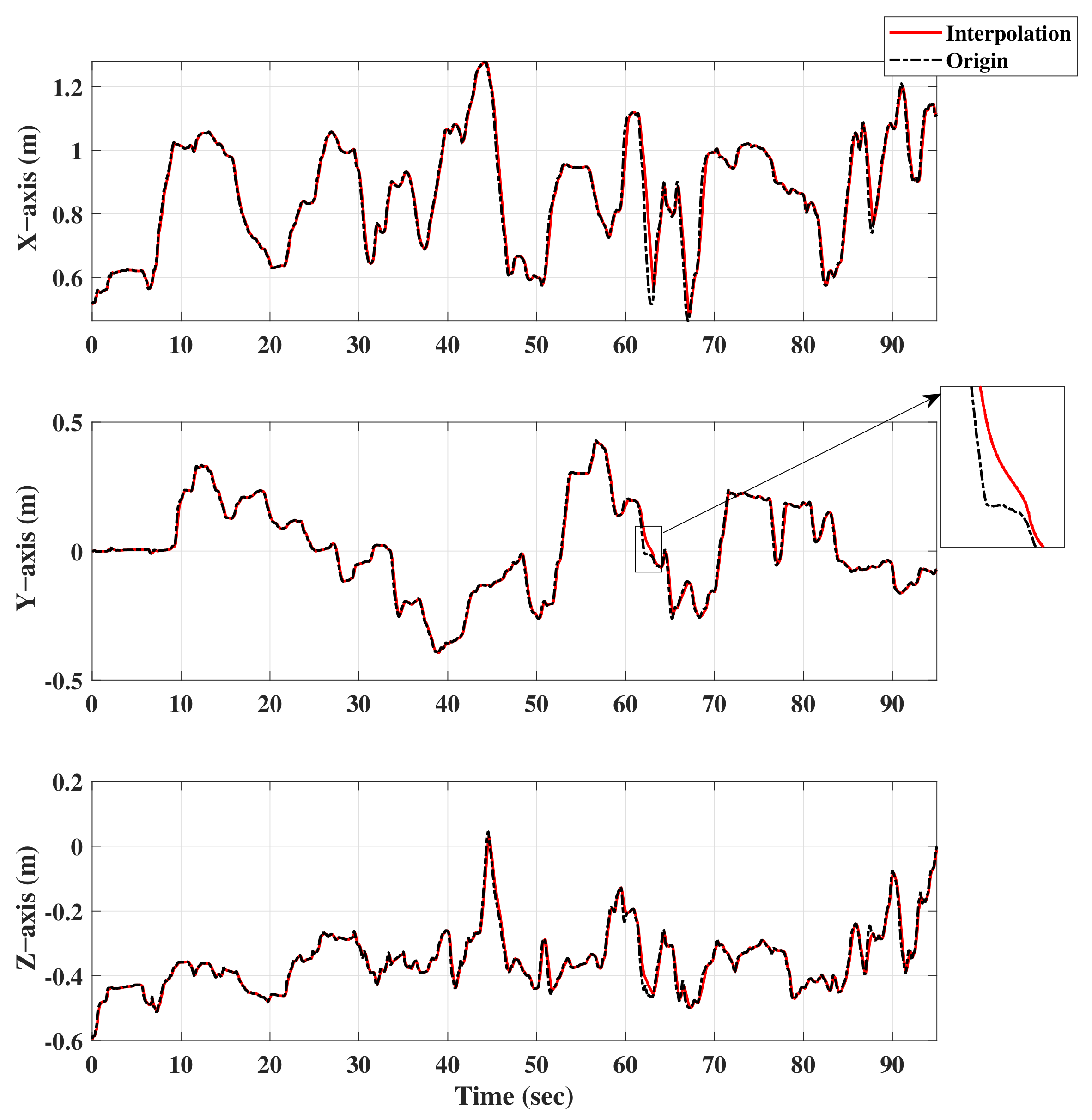
2.2.2. Velocity-Limited Interpolator

Due to fact that the control signal through the master–slave workspace mapping method comes from the manual setting of the operator, it is inevitable that there will be the velocity mutation of the end-pose discrete point sequence caused by a small chattering of the operation. Therefore, this section proposes a velocity-limited interpolator to generate discrete path points with a constant time interval in Cartesian space. The general form of n-th path interpolation is as follows:
p s i T n = p s i T n 1 + d i T n · o i T n
where p s i is the discrete interpolation points; T n is the n t h time interval; d i and o i is the distance between ( n 1 ) t h and n t h interpolation points, and the orientation of n t h interpolation point which can be written as follows:
d i = v max T n T n 1 tanh p f p s i v max T n T n 1 o i = p f p s i p f p s i
where p f is the final end-pose of hydraulic manipulator and v m a x is the maximum velocity limitation.
Trajectory p s i generated by a velocity-limited interpolator can indirectly adjust the velocity of the interpolated trajectory according to the distance between the final pose and the current pose, and ensure that the velocity direction of the trajectory is always toward the final target point.

2.2.3. Inverse Kinematic Solver

Because the essence of controlling the hydraulic manipulator is to control the manipulator angle of each joint, it is necessary to decouple the interpolated end-pose discrete point sequence p s i through the inverse kinematics solver to obtain the joint discrete point sequence q i of each joint, and the conversion function I k c can be written as follows:
q i = I k c ( p s i )
Since the inverse kinematics solution process for different structures of manipulators is different, the specific solution process of the inverse kinematics solver is not given in this section.

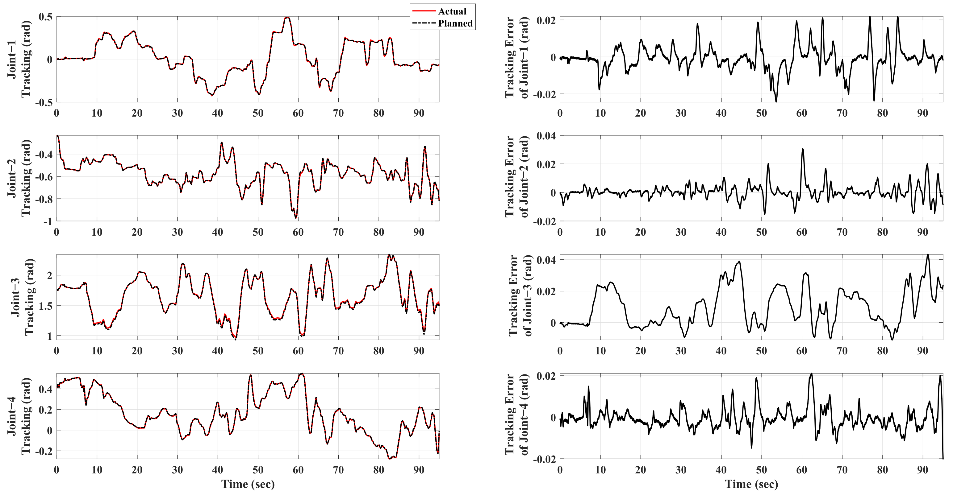
2.2.4. Slave Joint Trajectory Planner

After obtaining the joint target angle discrete point sequence after the inverse kinematics solution, it is necessary to convert the discrete point sequence into a continuous trajectory in the joint space as the control target input of the controller proposed in Section 2.2.5. There are abundant research achievements on path planning at present. For example, Sandi et al. proposed a generic algorithm by using range and average recommendations, then simulated announcing using a linear and geometric cooling strategy and differential evolution, so as to realize path planning optimization of six degrees of freedom robot manipulators [28]. Pavol et al. proposed a new method that can calculate the trajectory of any differentiable plane curve. This method can give an accurate analytical solution without using free radicals [29].
However, in the teleoperation framework designed in this paper, the target trajectory of designed manipulator controller needs to satisfy the property of third-order differentiability (the detailed description is mentioned in Section 2.2.5). Thus, in this section, a four-dimensional cubic B-spline planner is chosen to process the target angle discrete point sequence, and finally generate the third-order differentiable control target trajectory.
Describing the exact form of the base function of B-spline is defined by the Cox–de Boor iteration as follows:
B i , p ( ) = i i + p i B i , p 1 ( ) + i + p + 1 i + p + 1 i + 1 B i + 1 , p 1 ( ) B i , 0 ( ) = 1 , i < i + 1 0 , else
where B i , p ( ) means the i t h segment of p-order B-spline base function; i is the i t h element in the knot sequence. In addition, the B-spline itself is defined in the parametric equation form as follows:
C p ( ) = i = 0 n B i , n ( ) C P i
where n is the length of control point sequence of B-spline; and C P i is the i t h control points of B-spline, which is a series of points and every point is in the space with the dimension number of B-spline.
Based on above content, a real-time trajectory planner based on four-dimensional cubic B-splined is constructed as follows:
q d ( t ) = i = 0 3 B i , 3 t T s t T s q i i + t T s 3 T s
where T s represents time interval during trajectory planner. Through Equation (8), a third order B-spline trajectory is generated by slave joint trajectory planner and input to the slave controller as the control target trajectory.

2.2.5. Slave Manipulator Controller

In this section, the high-order dynamic model of the hydraulic manipulator is given, and based on which a high-performance adaptive robust controller is designed.
The dynamic model of hydraulic manipulator in state space can be written as follows:
x ˙ 1 = x 2 x ˙ 2 = l x 1 x 3 C x 2 M ( D G ) M + Δ 1 x ˙ 3 = g ( x ) u l x 1 A i 2 V i + A o 2 V o x 2 + A i V i Q i Δ + A o V o Q o Δ + Δ 2 y = u
where x = x 1 , x 2 , x 3 T = q , q ˙ , P 1 A 1 P 2 A 2 / M T . q represents the vector consisting of joint angles. M, C, and G respectively represents the manipulator inertia matrix, the Coriolis/centrifugal matrix, and the gravitational matrix. D is the disturbance torque vector. All the uncertain nonlinearities during operation can be merged into Δ 1 , and the Δ 2 represents the sum of uncertain nonlinearities in a hydraulic system. P i , P o are the pressure vector in the oil inlet and return chambers of all joint hydraulic cylinders, respectively. A i , A o represents the effective area of the joint hydraulic cylinder respectively of the oil inlet and return chamber. l is the linear displacements of the hydraulic cylinder rods. V i and V o respectively represent the volume of oil inlet and return chamber in a hydraulic cylinder. Q i Δ , Q o Δ represent the flow disturbance of oil inlet chamber and oil return chamber. u is the final control input. k q i , k q o is the gain coefficients of inlet and return flow. g i ( P i , x v ) and g o ( P o , x v ) is inlet and return flow conversion function.
By setting appropriate parameters θ , Equation (8) can be simplified as:
x ˙ 1 = x 2 x ˙ 2 = x 3 + θ T Φ 1 + Δ 1 x ˙ 3 = θ 4 u + θ T Φ 2 + Δ 2 y = u
where Φ 1 , Φ 1 is the corresponding parameter regression matrix. Due to the uncertainty of the dynamic model of the hydraulic manipulator, the accurate θ cannot be obtained. In the process of controller design, the adaptive method mention later is used to obtain the estimated value of θ which is called θ ^ , and the estimation error is represented by θ ˜ .
As shown in Equations (9) and (10), the dynamic model of the hydraulic manipulator is a high-order nonlinear model, so the backstepping method is used to deal with the high-order characteristics of the model, and an adaptive robust nonlinear controller is designed to control the hydraulic manipulator.
Step I
The joint tracking error is defined as e 1 = x 1 x 1 d . The filtered tracking error e 2 and e 3 can be defined as:
e 2 = e ˙ 1 + k 1 e 1 = x 2 α 1 e 3 = x 3 α 2
where k 1 is the feedback gain, and α represents the virtual control law, which can be designed as:
α 2 d = α 2 a + α 2 s 1 + α 2 s 2 α 2 a = θ ^ T Φ 1 + x ¨ 1 d α 2 s 1 = k 2 e 2
where k 2 is the feedback gain. α 2 s 2 is the uncertain nonlinear compensation part of α 2 d , which needs to satisfy the following conditions:
e 2 α 2 s 2 0 e 2 θ ˜ T Φ 1 + α 2 s 2 + Δ 1 ζ 1
where ζ 1 is a designed parameter that can be infinitesimal.
Step II
In Step II, the total differential of α 2 is calculated firstly. Since the term α 2 ˙ contains unknown signals, it can be grouped into known and unknown parts, i.e., α 2 c ˙ and α 2 u ˙ , which can be expressed as:
α ˙ 2 c = α 2 t + α 2 x 1 x 2 + α 2 x ^ 2 x ˙ ^ 2 α ˙ 2 c = α 2 x ^ 2 x ˙ ˜ 2 + α 2 θ θ ˙ ^
where α 2 t including x 1 d , which explains why the control target trajectory of the controller needs to satisfy the properties of third-order differentiability.
The known part α 2 c ˙ can be compensated in the design of final control input, and the unknown part is treated as disturbance handled by the robust control law. The final control input u d can be designed as:
u d = u a + u s 1 + u s 2 u a = θ ^ T Φ 2 + α ˙ 2 c u s 1 = k 3 e 3 θ 4 min
where k 3 is the feedback gain. u s 2 is the uncertain nonlinear compensation part of u d that needs to satisfy the following conditions:
e 3 u s 2 0 e 3 θ ˜ T Φ 2 + α ˙ 2 n + Δ 2 ζ 2
where ζ 2 is a designed parameter that can be infinitesimal.
The adaptive law for θ is designed as follows:
θ ^ ˙ = Proj θ ^ Γ · Φ 1 e 2 + Φ 2 e 3
where Γ is a positive definite gain matrix, and the projection mapping is defined in [30] as:
Proj θ ^ ( x ) = 0 if θ ^ i = θ i max and x > 0 0 if θ ^ i = θ i min and x < 0 x otherwise

2.2.6. Joint Feedback Torque Generator

To ensure that the slave manipulator reaches the workspace boundary as little as possible, it is necessary to return the actual operation information of the slave side to the master side to generate the virtual repulsion force, and feed it back to the operator through the master robot, so as to provide guidance to the operator, and avoid the slave manipulator reaching the workspace boundary or, more seriously, the operation command requires an unreachable position of a slave hydraulic manipulator.
Because the boundary of the workspace only contains three-dimensional position information, there are usually more than three joints of the slave hydraulic manipulator. This paper replaces the feedback repulsion force with the joint feedback repulsion torque to more intuitively reflect whether each joint reaches the limit.
The joint feedback torque is generated as follows:
τ f = w τ d q min
where τ f is the joint feedback torque, and d q min = min q q max , q q min represents the minimum distance between current angle and corresponding joint limit. w τ is the joint repulsion torque generating function, which can be written as follows:
w τ ( ) = τ max e 0.5 e q max q min = q q max τ max e 0.5 e q max q min = q q min
where τ m a x is the artificial set maximum repulsion torque that the master manipulator feeds back to the operator in the process of teleoperation.

3. Experiment

A real-time system in the MATLAB/Simulink environments is applied to actualize the experiment, as shown in Figure 2, where a Phantom Omni is used for the master manipulator and a hydraulic manipulator with four degrees of freedom (DoF) is used as the slave manipulator.
The Phantom Omni is a six DoF manipulator with built-in commercial angle sensors and torque sensors. It can provide its end pose and angle of each joint and exert the torque feedback of the first three joints. In this experiment, the operator controlled the end-position and end-posture of the onimi by holding the end grip. Meanwhile, the operator could also feel the three-dimensional force feedback and joint torque in real time.
The slave hydraulic manipulator is a four DoF manipulator equipped with general joint angle sensors (Melexis MLX90316) and hydraulic cylinder pressure sensors (Gefran KS-E-E-ZB160). Through the method designed in this paper, the end-position and end-posture sent by the operator through the master manipulator can be converted into the control commands of the slave hydraulic manipulator. Based on the designed motion controller, the slave hydraulic manipulator can accurately realize the teleoperation commands sent by the operator.
In the experiment of this paper, the operator sent the free-motion command through the Phantom Omni on the master side. The command is finally executed by the hydraulic manipulator on the slave side through the designed teleoperation framework, and the repulsion torque is fed back in real-time during the execution process to reflect whether the hydraulic manipulator moves to the workspace boundary.
In addition, the schematic diagram of the physical configuration of the master–slave manipulator has also been drawn in Figure 2, and the structural parameters of the Phantom Omni and the slave hydraulic manipulator are shown in Table 1. It can be seen that the physical configuration and the number of DoF of the master manipulator and the slave manipulator are different. It can be seen from the above information that the physical configuration of the master manipulator and the slave manipulator is different, the number of DoF is inconsistent, and the difference in structural parameters also leads to the different workspace range of these two manipulators. Considering that, in common practical industrial occasions of teleoperation of hydraulic manipulators, the operator sends operating commands through an integrated electric manipulator at a distance, and the slave hydraulic manipulator in the working environment operates according to the instructions. The experimental platform set up in this paper is similar to the actual situation, which means it is representative. Therefore, it is reasonable to verify the reliability of the designed method and evaluate its performance through this experimental platform.

4. Results and Discussion

Since the structure of the Omni robot is different from that of the hydraulic manipulator, the teleoperation control command is projected into the workspace of the slave manipulator through the master–slave workspace mapping method. The specific mapping results are shown in Figure 3.
In terms of the moving trend of the mapping result, it can be seen from Figure 3 that the trend of the end-position control target trajectory of the master robot and the slave manipulator in the Cartesian coordinate system is similar. In terms of workspace utilization, the maximum motion range of the main end manipulator was 10.2 × 14.9 × 8.5 (cm) during the whole experiment, and the maximum motion range of the slave end manipulator was 81.6 × 82.6 × 64.1 (cm). These data show that, when the master manipulator controlled by the operator moves to the maximum extent in the allowable workspace, which is shown in Table 1 (the workspace utilization rate is w s m = 13.2 × 14.9 × 8.5 16 × 16 × 10 = 65.3 % ), the slave manipulator can also make the maximum use of its workspace (workspace utilization is w s s = 81.6 × 82.6 × 64.1 94.1 × 96.1 × 73.4 = 65.9 % ). This result shows that the heterogeneous matching algorithm designed in this paper can ensure that the master–slave workspace mapping can be realized under the condition that the control instructions issued by the operator are not distorted (the trend is the same).
The velocity-limited interpolation result is shown in Figure 4. It can be seen from the result that the designed interpolator ensures that the velocity of the slave trajectory requiring inverse kinematics conversion is bounded (as shown in the enlarged figure of Figure 4, the velocity constraint can be carried out through the interpolation algorithm when the target motion velocity changes too much).
The trajectory planning result is shown as Figure 5. For simplicity of expression, in this chapter, J s 1 is represented as Joint-1, and the others are the same. It can be seen that the trajectory avoids the problems of not smoothened motion trajectory and discontinuous motion velocity caused by manual operation during the experiment and meets the requirements of the ideal trajectory emphasized in the previous controller design part. The planner planning error and final control error are shown together in Table 2. From the data in Table 2, it can be concluded that the planner designed in this paper can obtain planning results that meet the target trajectory requirements of the nonlinear controller with a very small error. The maximum planning error of the joint is 0.03 rad, and the maximum planning error of the three axes is 2.2 cm.
The final control effect of the hydraulic manipulator is shown in Figure 6 and Figure 7. Through the control results, it can be seen that, in the whole process of teleoperation control, the maximum tracking error of each joint of the end hydraulic manipulator is guaranteed to be within 0.04 rad, and the maximum tracking error of the end three-dimensional coordinates is within 2 cm. The results show that the teleoperation framework designed in this paper can guarantee the teleoperation performance of the hydraulic manipulator in the case of master–slave heterogeneity well, that is, it can satisfy the requirements of the hydraulic manipulator teleoperation with the operating accuracy up to 0.02 m under the condition of master–slave heterogeneity.
The results of the main side torque feedback are shown in Figure 8. It can be seen that the operator can always feel the joint virtual feedback repulsion torque in the process of actual teleoperation, which can enhance the operating transparency of the operator.
To sum up, through the experimental results of the slave side, it can be seen that the operator’s teleoperation intention can be converted to the control target of the slave hydraulic manipulator, and the slave hydraulic manipulator can complete the operation command accurately. According to the results of the master side, the operator can receive the virtual repulsion feedback in the whole process of teleoperation. These results can ensure that the designed teleoperation framework based on heterogeneous matching can realize the hydraulic manipulators’ teleoperation effectively.

5. Conclusions

This work proposes a teleoperation framework based on master–slave heterogeneous matching and nonlinear precise motion control for hydraulic manipulators. To be specific, the workspace mapping algorithm is proposed to project the master control command into slave manipulator workspace to cope with the master–slave heterogeneity of hydraulic manipulator teleoperation. In addition, a velocity-limited path interpolator is proposed to generate discrete path points with adjustable maximum velocity in three-dimensional space, and a trajectory planner based on four-dimensional cubic B-spline is designed to generate the third-order differentiable desired trajectory of joint angles. In addition, in order to deal with the high-order nonlinear characteristics of the hydraulic manipulator dynamic model and the external disturbance in the operation process, an adaptive robust controller is proposed to achieve good control performance. Then, the joint virtual torque generator at master side is introduced to provide the operator with joint virtual repulsion torque, so as to enhance the operating transparency of the operator. Finally, the specialized experiment is set up to evaluate the effectiveness of the designed teleoperation framework, and the experimental results show that the designed method can satisfy the teleoperation requirements of the hydraulic manipulator with the operating accuracy up to 0.02 m under the condition of master–slave heterogeneity. In the future work, our team will apply the method proposed in this paper to the industrial manipulator in the actual teleoperation working environment to complete tasks such as target grasping, underwater pipe and cable docking, sample collection in harsh environments, etc. In addition, we will continue to optimize the heterogeneous matching method that can cope with the inconsistency of the master–slave robot configuration, and consider how to further improve the telepresence of operators in the process of teleoperation.

Author Contributions

Conceptualization, Z.C. and S.Z. (Shiqiang Zhu); methodology, S.Z. (Shizhao Zhou), C.S. and W.L.; software, S.Z. (Shizhao Zhou), C.S. and W.L.; funding acquisition, Z.C. and Y.N.; investigation, S.Z. (Shizhao Zhou) and W.L.; writing—original draft preparation, S.Z. (Shizhao Zhou) and C.S.; writing—review and editing, Z.C. and Y.N.; project administration, Z.C. and S.Z. (Shiqiang Zhu). All authors have read and agreed to the published version of the manuscript.

Funding

This work was funded by the Hainan Provincial National Natural Science Foundation of China (No. 521MS065), the Key R&D Program of Zhejiang Province (No. 2021C03013), Ten Thousand Talents Program of Zhejiang Province (Grant No. 2019R51010), and a Scientific Research Fund of the Zhejiang Provincial Education Department (No. Y202148327).

Institutional Review Board Statement

Not applicable.

Informed Consent Statement

Not applicable.

Data Availability Statement

The data that support the findings of this study are available from the corresponding author upon reasonable request.

Conflicts of Interest

The authors declare no conflict of interest.

Nomenclature

CharacterMeaning
p m , p s Pose of master robot & slave hydraulic manipulator
R , S , T Rotation transformation matrix, scale transformation matrix, translation
transformation matrix
σ Rotation angle around the z-axis
p s i Discrete interpolation points on the slave side
T n n t h time interval
p f Final end-pose of hydraulic manipulator
v m a x Maximum velocity limitation
q i Joint discrete point sequence
I k c Inverse kinematics conversion function
B i , p i t h segment of p-order B-spline base function
nLength of control point sequence of B-spline
C P i i t h control points of B-spline
T s Time interval during trajectory planner
xDefined states in dynamic state space
q , q ˙ Vector consisting of joint angles and velocity
M , C , G Inertia matrix, Coriolis/centrifugal matrix, Gravitational matrix
DDisturbance torque vector
Δ Uncertain nonlinearities in hydraulic system
P i , P o Pressure vector in the oil inlet & return chambers of all joint hydraulic cylinders
A i , A o Effective area of joint hydraulic cylinder of the oil inlet & return chamber
V i , V o Volume of oil inlet & return chamber in hydraulic cylinder
Q i Δ , Q o Δ Flow disturbance of oil inlet & return chamber
uFinal control input
k q i , k q o Gain coefficients of inlet & return flow
g q i , g q o Inlet & return flow conversion function
θ Model parameter
Φ Parameter regression matrix
e 1 , e 2 , e 3 Motion tracking error
k 1 , k 2 , k 3 Feedback control gain
α 1 , α 2 , α 3 Visual input
α 2 d , α 2 a , α 2 s 1 , α 2 s 2 Virtual control law in Step I during backstepping controller design
u d , u a , u s 1 , u s 2 Virtual control law in Step II during the backstepping controller design
ζ 1 , ζ 2 Designed infinitesimal control parameter
ProjModel parameter adaptive law
Γ Model parameter adaptive coefficient
τ f Joint feedback torque
w τ Joint repulsion torque generating function
τ m a x Artificial set maximum repulsion torque

References

  1. Cheng, M.; Zhang, J.; Xu, B.; Ding, R.; Wei, J. Decoupling Compensation for Damping Improvement of the Electrohydraulic Control System With Multiple Actuators. IEEE/ASME Trans. Mechatron. 2018, 23, 1383–1392. [Google Scholar] [CrossRef]
  2. Won, D.; Kim, W.; Tomizuka, M. High-gain-observer-based integral sliding mode control for position tracking of electrohydraulic servo systems. IEEE/ASME Trans. Mechatron. 2017, 22, 2695–2704. [Google Scholar] [CrossRef]
  3. Lin, T.; Lin, Y.; Ren, H.; Chen, H.; Chen, Q. A Double Variable Control Load Sensing System for Electric Hydraulic Excavator. Energy 2021, 223, 119999. [Google Scholar] [CrossRef]
  4. Correa, M.; Cárdenas, D.; Carvajal, D.; Ruiz-del Solar, J. Haptic Teleoperation of Impact Hammers in Underground Mining. Appl. Sci. 2022, 12, 1428. [Google Scholar] [CrossRef]
  5. Perez-del Pulgar, C.J.; Smisek, J.; Rivas-Blanco, I.; Schiele, A.; Muñoz, V.F. Using Gaussian Mixture Models for Gesture Recognition During Haptically Guided Telemanipulation. Electronics 2019, 8, 772. [Google Scholar] [CrossRef] [Green Version]
  6. Ye, Y.; Pan, Y.J.; Hilliard, T. Bilateral teleoperation with time-varying delay: A communication channel passification approach. IEEE/ASME Trans. Mechatron. 2013, 18, 1431–1434. [Google Scholar] [CrossRef]
  7. Chen, Z.; Huang, F.; Yang, C.; Yao, B. Adaptive fuzzy backstepping control for stable nonlinear bilateral teleoperation manipulators with enhanced transparency performance. IEEE Trans. Ind. Electron. 2019, 67, 746–756. [Google Scholar] [CrossRef]
  8. Chen, Z.; Huang, F.; Sun, W.; Gu, J.; Yao, B. RBF-neural-network-based adaptive robust control for nonlinear bilateral teleoperation manipulators with uncertainty and time delay. IEEE/ASME Trans. Mechatron. 2019, 25, 906–918. [Google Scholar] [CrossRef]
  9. Lampinen, S.; Koivumäki, J.; Mattila, J. Full-dynamics-based bilateral teleoperation of hydraulic robotic manipulators. In Proceedings of the 2018 IEEE 14th International Conference on Automation Science and Engineering (CASE), Munich, Germany, 20–24 August 2018; pp. 1343–1350. [Google Scholar] [CrossRef]
  10. Lyu, L.; Chen, Z.; Yao, B. Advanced valves and pump coordinated hydraulic control design to simultaneously achieve high accuracy and high efficiency. IEEE Trans. Control Syst. Technol. 2020, 29, 236–248. [Google Scholar] [CrossRef]
  11. Hyon, S.H.; Suewaka, D.; Torii, Y.; Oku, N. Design and experimental evaluation of a fast torque-controlled hydraulic humanoid robot. IEEE/ASME Trans. Mechatron. 2016, 22, 623–634. [Google Scholar] [CrossRef]
  12. Ge, L.; Quan, L.; Zhang, X.; Zhao, B.; Yang, J. Efficiency improvement and evaluation of electric hydraulic excavator with speed and displacement variable pump. Energy Convers. Manag. 2017, 150, 62–71. [Google Scholar] [CrossRef]
  13. Bu, F.; Yuo, B. Desired compensation adaptive robust control of single-rod electro-hydraulic actuator. In Proceedings of the 2001 American Control Conference (Cat. No. 01CH37148), Arlington, VA, USA, 25–27 June 2001; Volume 5, pp. 3926–3931. [Google Scholar] [CrossRef]
  14. Helian, B.; Chen, Z.; Yao, B.; Lyu, L.; Li, C. Accurate motion control of a direct-drive hydraulic system with an adaptive nonlinear pump flow compensation. IEEE/ASME Trans. Mechatron. 2020, 26, 2593–2603. [Google Scholar] [CrossRef]
  15. Lyu, L.; Chen, Z.; Yao, B. Development of pump and valves combined hydraulic system for both high tracking precision and high energy efficiency. IEEE Trans. Ind. Electron. 2018, 66, 7189–7198. [Google Scholar] [CrossRef]
  16. Zhou, S.; Shen, C.; Xia, Y.; Chen, Z.; Zhu, S. Adaptive robust control design for underwater multi-dof hydraulic manipulator. Ocean Eng. 2022, 248, 110822. [Google Scholar] [CrossRef]
  17. Yao, J.; Deng, W.; Jiao, Z. RISE-Based Adaptive Control of Hydraulic Systems With Asymptotic Tracking. IEEE Trans. Autom. Sci. Eng. 2015, 14, 1524–1531. [Google Scholar] [CrossRef]
  18. Deng, W.; Yao, J. Asymptotic tracking control of mechanical servosystems with mismatched uncertainties. IEEE/ASME Trans. Mechatron. 2020, 26, 2204–2214. [Google Scholar] [CrossRef]
  19. Yao, J.; Deng, W. Active Disturbance Rejection Adaptive Control of Hydraulic Servo Systems. IEEE Trans. Ind. Electron. 2017, 64, 8023–8032. [Google Scholar] [CrossRef]
  20. Petrović, G.R.; Mattila, J. Mathematical modelling and virtual decomposition control of heavy-duty parallel–serial hydraulic manipulators. Mech. Mach. Theory 2022, 170, 104680. [Google Scholar] [CrossRef]
  21. Mattila, J.; Koivumäki, J.; Caldwell, D.G.; Semini, C. A survey on control of hydraulic robotic manipulators with projection to future trends. IEEE/ASME Trans. Mechatron. 2017, 22, 669–680. [Google Scholar] [CrossRef]
  22. Koivumäki, J.; Mattila, J. Stability-guaranteed impedance control of hydraulic robotic manipulators. IEEE/ASME Trans. Mechatron. 2016, 22, 601–612. [Google Scholar] [CrossRef]
  23. Shen, W.; Wang, J. An integral terminal sliding mode control scheme for speed control system using a double-variable hydraulic transformer. ISA Trans. 2019, 124, 386–394. [Google Scholar] [CrossRef]
  24. Shtessel, Y.; Taleb, M.; Plestan, F. A novel adaptive-gain supertwisting sliding mode controller: Methodology and application. Automatica 2012, 48, 759–769. [Google Scholar] [CrossRef]
  25. Chen, Z.; Yan, S.; Yuan, M.; Yao, B.; Hu, J. Modular development of master–slave asymmetric teleoperation systems with a novel workspace mapping algorithm. IEEE Access 2018, 6, 15356–15364. [Google Scholar] [CrossRef]
  26. Chen, Z.; Huang, F.; Chen, W.; Zhang, J.; Sun, W.; Chen, J.; Gu, J.; Zhu, S. RBFNN-based adaptive sliding mode control design for delayed nonlinear multilateral telerobotic system with cooperative manipulation. IEEE Trans. Ind. Inform. 2019, 16, 1236–1247. [Google Scholar] [CrossRef]
  27. Deng, H.; Gong, D.; Yu, J.; Zuo, G. Research on Intuitive Tele-operation Motion Mapping Algorithm for Omnidirectional Mobile Heterogeneous Slave Arm System. In Proceedings of the 2020 10th Institute of Electrical and Electronics Engineers International Conference on Cyber Technology in Automation, Control, and Intelligent Systems (CYBER), Xi’an, China, 10–13 October 2020; pp. 67–72. [Google Scholar] [CrossRef]
  28. Egota, S.B.; Aneli, N.; Lorencin, I.; Saga, M.; Car, Z. Path planning optimization of six-degree-of-freedom robotic manipulators using evolutionary algorithms. Int. J. Adv. Robot. Syst. 2020, 17, 1–16. [Google Scholar] [CrossRef] [Green Version]
  29. Bozek, P.; Lozkin, A.; Gorbushin, A. Geometrical Method for Increasing Precision of Machine Building Parts. Procedia Eng. 2016, 149, 576–580. [Google Scholar] [CrossRef] [Green Version]
  30. Yao, B.; Bu, F.; Reedy, J.; Chiu, G. Adaptive robust motion control of single-rod hydraulic actuators: Theory and experiments. IEEE/ASME Trans. Mechatron. 2002, 5, 79–91. [Google Scholar] [CrossRef]
Figure 1. Overall diagram of designed teleoperation framework with heterogeneous matching.
Machines 10 00536 g001
Figure 2. Real-time experimental platform.
Machines 10 00536 g002
Figure 3. Master–slave Workspace Mapping Result.
Machines 10 00536 g003
Figure 4. Velocity-limited interpolation results.
Machines 10 00536 g004
Figure 5. Trajectory planning results.
Machines 10 00536 g005
Figure 6. Control result of joint space.
Machines 10 00536 g006
Figure 7. Control result of Cartesian space.
Machines 10 00536 g007
Figure 8. Torque feedback results.
Machines 10 00536 g008
Table 1. Structural parameters.
Structural Parameters
of Phantom Omini
ValueStructural Parameters
of Slave Manipulator
Value
l m 1 3.5 cm l s 1 23.0 cm
l m 2 15.2 cm l s 2 26.0 cm
l m 3 13.8 cm l s 3 24.5 cm
Range of J m 1 120 ° l s 4 19.5 cm
Range of J m 2 90 ° Range of J s 1 120 °
Range of J m 3 135 ° Range of J s 2 120 °
Range of J m 4 360 ° Range of J s 3 110 °
Range of J m 5 135 ° Range of J s 4 100 °
Range of J m 6 360 °
Three-axis
workspace range
16 × 16 × 10 (cm)Three-axis
workspace range
94.1 × 96.1 × 73.4 (cm)
Table 2. Experimental Result Parameters.
Maximum
Planning Error
Maximum
Control Error
Joint-10.01 rad0.02 rad
Joint-20.03 rad0.03 rad
Joint-30.01 rad0.04 rad
Joint-40.02 rad0.02 rad
x-axis2.17 cm1.06 cm
y-axis2.20 cm2.03 cm
z-axis1.91 cm1.85 cm
Publisher’s Note: MDPI stays neutral with regard to jurisdictional claims in published maps and institutional affiliations.

