1. Introduction
With the development of science and technology, servo systems are increasingly used in many fields, such as aerospace [
1], metallurgy, transportation, military, electrical, electronic, and energy. In engineering practice, the control performance requirements of servo systems have always been an important issue. There is an urgent need to move towards the goals of high precision, high-frequency response, high efficiency, high reliability, and high energy saving [
2]. The nonlinearity of the mechanical gap is an important characteristic of the high precision positioning of the system [
3,
4].
An electromechanical hydraulic actuation system must satisfy the dynamic transmission and motion requirements of the system through mechanical mechanisms. Thus, the mechanical transmission structure is an important component of servo systems. Considering the manufacturing and assembly errors of the servo system, as well as the hinge connection or screw connection between the transmission mechanisms, kinematic pair clearance is inevitably generated [
5,
6,
7,
8]. The nonlinearity of the clearance is destructive, and the clearance of the kinematic pair causes the actual motion trajectory of the mechanism to deviate from the expected trajectory, significantly affecting the response speed, control accuracy, and motion performance of the system. The existence of kinematic pair clearance will also lead to a collision between the mechanisms, resulting in elastic vibration, excess force, noise, and wear [
9], which may eventually lead to oil contamination and loss of control or damage to the system. According to statistical analysis, approximately 30–80% of equipment damage is due to wear between mechanical components [
10], and wear is also one of the causes of the subsequent failure of mechanical components [
11,
12,
13]. Therefore, it is of great significance to carry out theoretical and technical research on the nonlinear clearance control of servo systems. When there is clearance nonlinearity in a mechanical system, the clearance characteristics must be considered in the control strategy to achieve clearance compensation control, thereby ensuring system control accuracy [
14]. To improve the design, analysis, and prediction methods, it is necessary to have a good understanding of clearance theory.
Due to the limitations of machining accuracy, installation, test conditions, and other conditions, there will inevitably be clearances in the actual system, which seriously affects the control accuracy of the servo system. It is because of the clearances between the connecting parts in a system, that collisions inevitably occur during movement, resulting in a large impact force, aggravating the wear of the parts, and further accelerating the fatigue damage of connecting parts. Collision caused by the clearance at the connection also produces serious noise. For high-speed mechanisms, the impact of clearance is even greater. In recent decades, research on clearance and its compensation control scheme has been an important direction in engineering applications. To improve design performance, it is necessary to first establish an accurate mathematical model of clearance [
15,
16,
17] to summarize the physical phenomena caused by the nonlinearity of clearance. Therefore, it is of great significance to study the clearance compensation control strategy to realize high-precision control of the servo system.
The rest of this paper is organized as follows.
Section 2 briefly describes the purpose and implications of clearance nonlinearity.
Section 3 presents the literature based on the clearance model compensation strategy, which includes two parts: the clearance nonlinear model and the clearance model-based control strategy.
Section 4 reviews the literature based on model-free compensation control strategies, including the mechanism elimination method and model-free clearance control strategy.
Section 5 discusses and compares the existing backlash compensation control strategies.
Section 6 provides a summary and offers insights into the refinement and development of future clearance nonlinear control theories.
2. Purpose and Connotation of Nonlinear Control of Clearance
Non-linearity is widely present in production and life, and it has various manifestations. Nonlinear problems can be divided into memoryless and memory nonlinear problems. The reason why the former problems are called memoryless, zero memory, or static is because the output of a nonlinear system at any time is determined only by the input at that time, and has nothing to do with the historical input. Typical memoryless nonlinear characteristics include repeater nonlinearity, saturation nonlinearity, dead-band nonlinearity, and quantization nonlinearity. The nonlinear characteristic of memory implies that the output at any time is related to all historical inputs. Typical memory nonlinear characteristics include hysteresis nonlinearity and clearance nonlinearity. The nonlinear characteristic of backlash is common in transmission systems, such as gears, and is a typical nonlinear characteristic. The characteristic of clearance nonlinearity is that when the direction of the input quantity changes, the output quantity remains unchanged, and the output quantity does not change until the change in the input quantity exceeds a certain value. A mechanical transmission generally has clearance, and clearance in gear transmission is the most obvious example.
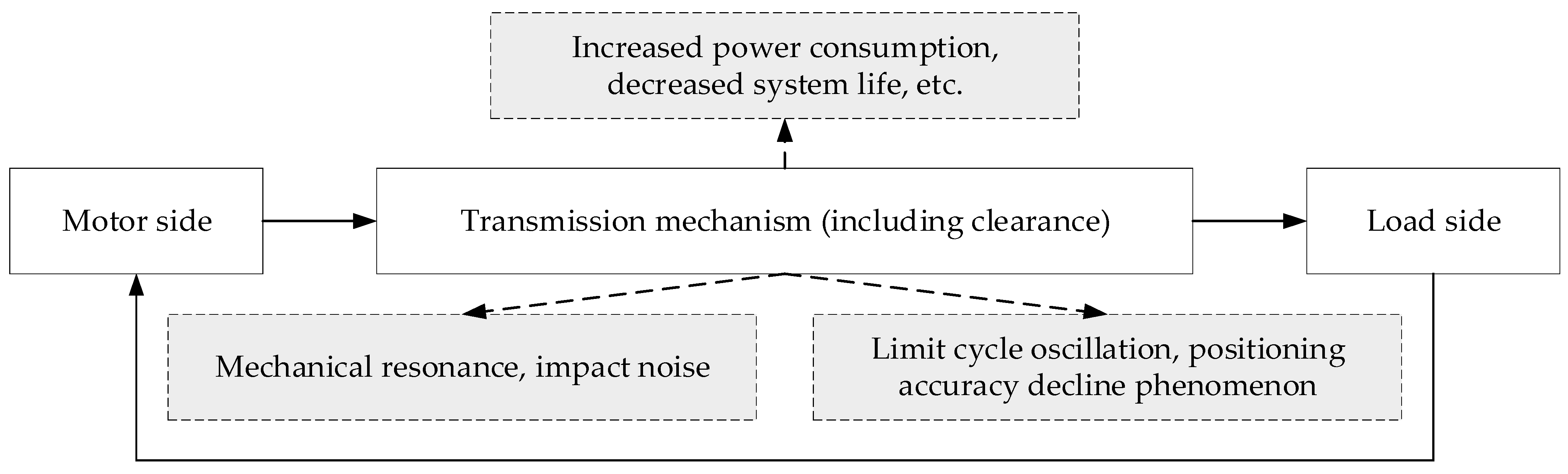
Clearance exists widely between the driving and driven parts, which are not directly connected in mechanical transmission. The existence of clearance nonlinearity causes phase lag, input saturation, limited cycle oscillation, and other phenomena [
18], which significantly reduce the stability of the system and limit the static and dynamic control performance. When mechanical resonance is induced by the limited stiffness of the transmission, the existence of clearance nonlinearity further aggravates mechanical resonance, which has three manifestations in the servo system: axial, lateral, and torque [
19]. The effects of the clearance factors are shown in
Figure 1. Various phenomena show that the clearance characteristic is the key factor affecting the dynamic performance and control precision of the servo system, and it is also the main bottleneck in the development of high-precision electromechanical-hydraulic servo actuation systems. Therefore, in the research and mechanism design of the actuating system, sufficient attention must be paid to the influence of clearance, and appropriate strategies should be adopted to reduce or even eliminate its negative influence.
The clearance characteristic sources exhibit random and difficult-to-measure properties. Many researchers have qualitatively analyzed this feature from the aspect of structure [
20,
21,
22], but it is accompanied by an increase in cost and complexity of structural design, and the high requirement of machining accuracy has discouraged many scholars. Then, from the control point of view [
23,
24,
25], for systems with clearances, we study control methods to improve and enhance the performance of closed-loop systems. Clearance compensation control strategies are often divided into two types: clearance model and model-free compensation.
3. Control Strategy Based on Clearance Model
3.1. Clearance Model
The clearance contact model is based on the mechanical model and is represented by describing the interaction force between the components in the case of mutual contact.
3.1.1. Two-State Model of Contact-Separation
Research on clearance nonlinearity can be traced back to the year 1977. Between 1973 and 1977, Dubowsky [
26,
27,
28,
29] proposed a nonlinear ‘contact-separation’ two-state model of clearance by studying the effect of clearance on the connection force of the planar mechanism.
3.1.2. Three-State Model of Contact-Separation-Collision
Miedema et al. [
30] proposed a three-state model of ‘contact-separation-collision’ with higher precision clearance nonlinearity when studying mechanical hinge clearance. The establishment principle of the model is to divide the relative motion of each component between the kinematic pairs into contact, separation, and collision. Based on this division mode, a three-state model of the clearance was established.
Soong et al. [
31] conducted theoretical analysis and experimental research on the dynamic effects of spherical hinges with radial clearance on the crank-slider mechanism. Combined with theoretical analysis and experimental research results, the three-state model of ‘contact-separation-collision’ of clearance was refined and expanded into four states of contact, separation, collision, and transition, and a nonlinear dynamic model of clearance was established based on the four states of the radial clearance of the spherical hinge.
3.1.3. Hysteresis Model
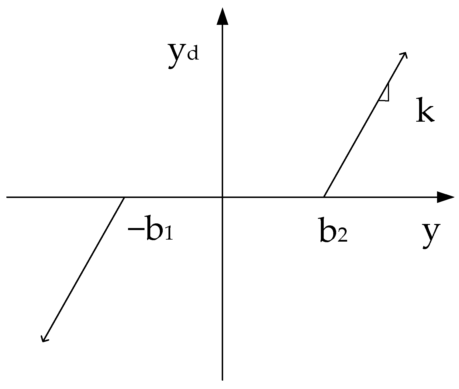
The hysteresis clearance model [
32] describes the relative displacement values of inputs and outputs. When the mechanism moves in one direction in the active part, to drive the follower to move the active part, the active part must move until the relative displacement breaks through the clearance area, to obtain contact with the follower. The output signal must produce a phase-lag phenomenon from the perspective of the dynamic response of the system. The input and output characteristic curves are shown in
Figure 2, where
is the left clearance of the system,
is the right clearance of the system,
is the positive maximum input of the clearance,
is the negative maximum input of the clearance, and
is the output displacement of the clearance.
As shown in
Figure 2, the mathematical expression for the hysteresis model describing the clearance is:
where
is the input displacement of the clearance.
The mathematical expression of another hysteresis clearance model is:
3.1.4. Vibro-Shock Model
The vibration-impact model [
33,
34] is another mathematical model that describes the nonlinearity of clearance and is analyzed from a mechanical point of view. First, the system was connected rigidly. According to the law of conservation of momentum, it can be considered that the energy deficit in the system can be described by the reflection coefficient. Subsequently, we consider the transmission mechanism. When the transmission mechanism is linear, it can be represented by the dead-zone model of clearance nonlinearity. When the transmission mechanism is nonlinear, a variable stiffness coefficient is introduced, and the nonlinearity of the clearance must be simultaneously described as time-varying and nonlinear at the same time. When rigidly connected, the master-slave mechanism is as follows:
where
is the reflection coefficient,
is the moment before the collision,
is the moment after the collision,
is the moment of inertia of the driving part, and
is the moment of inertia of the driven part.
3.1.5. Dead Zone Model
The dead zone model [
35] reflects the relationship between the displacement and the transmission force, the torque transfer relationship between the input and output subsystems, and the effects of stiffness and damping in the mechanism. When the input signal is at zero position, no signal output is generated. When the input signal is greater than, or less than, the dead-zone value, the system generates an approximately linearly correlated signal. The input and output curves of the dead zone model are shown in
Figure 3, where
is the left clearance of the system,
is the right clearance of the system, and
is the clearance gain coefficient.
As shown in
Figure 3, the mathematical expression for the dead zone model describing the clearance is:
where
is the clearance gain coefficient,
is the dead zone value,
is the relative displacement of the input signal,
m is the output torque,
.
3.1.6. Hertz Contact Law Model
Wan et al. [
36] used a contact force model based on Hertz’s contract law to describe the clearance characteristics of an electromechanical aileron actuation system. The model not only considers the influence of the nonlinear energy dissipation process but also solves the programming difficulty of the contact force model for collision detection. This equation can be expressed as follows:
where
is the normal contact force,
is the relative penetration depth, and
is the generalized contact stiffness. The value
is the restitution coefficient,
is the relative penetration velocity,
is the transition velocity,
and
are Poisson’s ratios of bearing and journal, respectively. Values
and
are Young’s moduli of bearing and journal, respectively,
and
are the maximum curvature radii of bearing and journal at the contact point, respectively and
and
are the minimum curvature radii of bearing and journal at the contact point, respectively. Finally,
is the angle of the tangent plane of bearing and journal at the contact point.
3.1.7. Logarithmic Clearance Model
Margielewicz et al. [
37] used a logarithmic function-based function approximation to describe clearance features in numerical experiments. The use of logarithmic functions is another approach in the study of clearance models that adequately describes the dynamics of the system. Undoubtedly, the advantage of the logarithmic function is that when the coefficients are fitted, it approximates the clearance characteristics, which reduces the computation time. A large value of
improves the convergence of the solution with respect to the discontinuous model, but increases the numerical computation time. A schematic of the gear clearance is shown in
Figure 4.
As shown in
Figure 4,
and
are the diameters of the disc,
and
are the moments of inertia,
is the spring element,
is the dissipative element,
is the gear fit error,
is the driving torque, and
is the load torque. Furthermore, the clearance model can be described as follows:
where
is a constant equal to half the clearance value,
, variable
is displacement. The introduction of variable
x, dependent on the dimensionless time, affects the width of the dead zone of the tooth clearance, now falling within the range limited by the values −1 and 1.
3.1.8. Hunt-Crossly Nonlinear Spring-Damping Model
Liu et al. [
38] ignored the vibration of a cradle and reflected the effect of barrel vibration through the equivalent stiffness integrated into the clearance contact model. The Hunt-Crossly nonlinear spring damping model is a classic contact collision model used to describe the contact force between the barrel and base according to the Lankaran-Nikravesh contact force model proposed by the Hunt-Crossly contact force model. The model considers aspects such as material properties, geometry, elastic deformation, energy dissipation, and coefficient of restitution. Therefore, the actual clearance acting stiffness is the series equivalent stiffness of the clearance contact stiffness and base equivalent stiffness, which is called the effective stiffness of the clearance nonlinearity. For the clearance nonlinear force, which represents the interaction force in the case of mutual contact and mutual separation, the expression is given by:
where
denotes the clearance value,
denotes the contact damping coefficient, and
denotes the effective stiffness of clearance nonlinearity. Then,
and
are the displacement response and velocity response at clearance location, respectively.
3.2. Control Strategy Based on Clearance Model
To sum up the introduction of the clearance model, the existing mathematical models are mostly based on the hysteresis model, the vibration-shock model, and the dead zone model. Three types of nonlinear clearance models were studied and improved. As shown in
Table 1, the hysteresis model focuses on describing the relative lag of the output, the position difference, and the lag of the master and slave parts during the transmission process. The dead zone model can more comprehensively express the influence of the clearance in the motion control system on the output performance. The vibro-impact model is suitable for multi-body dynamics studies. Three types of nonlinear clearance models were studied and improved. However, in practical applications, there are many limitations, such as the time-varying system position, velocity, and acceleration in actual motion and the accuracy of model parameter identification. A single nonlinear model of clearance is not sufficient to deal with the clearance disturbance, and it is necessary to study a control method to improve the performance of the system with clearance from the perspective of the control strategy.
3.2.1. Feedforward Compensation Method
The idea of feedforward compensation control is to compensate the control system according to the magnitude of the disturbance after the disturbance is generated and before the controlled variable changes according to the nonlinear model of the clearance.
Selmic et al. [
39] developed a clearance compensation method with a dynamic inversion structure and feedforward neural network compensation, as shown in
Figure 5, where the inversion error approximated the recoil inversion error and filter dynamics required for the inversion design. The neural network controller does not require preliminary offline training and its tuning is based on a modified Hebbian tuning law, which reduces the amount of control system computation compared to backpropagation. The feedforward neural network compensation controller uses actual filtered derivatives and provides rigorous stability proofing, using the Lyapunov theory. Simulation results show that the proposed compensation scheme improves the tracking performance of a nonlinear clearance system.
Mei et al. [
40] discussed a method based on the clearance feedforward compensation. On this basis, clearance compensation was achieved by adding the number of compensation pulses corresponding to the clearance measured at the initial and reverse direction points of the desired trajectory of the joint. Feedforward control, combined with clearance prediction technology, reduced the maximum position error of the system by 92.9% using low-cost gearboxes and had high positioning accuracy.
Rakotondrabe et al. [
41] proposed a multivariate approach for rate-independent hysteresis modeling and feedforward control in multi-degree-of-freedom (multi-DOF) piezoelectric actuators. To do this, the classic Prandtl-Ishlinskii (CPI) lag model was extended to multivariate analysis. Subsequently, based on the inverse multiplication structure and multivariate CPI model, a compensator was proposed. Furthermore, the inversion of the model was avoided. In addition to hysteresis suppression, the multivariate compensator allows for reduced cross-coupling between the axes, which is not possible using standard techniques.
Figure 6 shows the block diagram of the multivariable feedforward control structure.
Chen et al. [
42] designed an insulated gate bipolar transistor (IGBT) parameter identification method, a dead zone compensation method, and an inverter device. Compared with the traditional control strategy, it does not need to judge the current direction according to the sampling signal, and there is no reciprocating zero-crossing phenomenon, thereby avoiding its influence on the compensation effect.
This control method depends on the accuracy of the clearance model, and the adjustment effect of the feedback control method lags behind the disturbance effect, which is an unavoidable problem in the feedforward control.
3.2.2. Inverse Model Compensation Method
The idea behind clearance inverse compensation is to consider the clearance model as the object of inverse compensation. By introducing the model inverse into the control signal to offset the influence of clearance nonlinearity, the system is pseudo-linearized, and an appropriate control strategy is selected according to the specific system.
Katsura et al. [
43] computed the inverse system output based on a model and controls to provide positive feedback on the object position, based on the inverse system output. Ramakrishnan et al. [
44] provided a method for backlash compensation in a motion control system, including homing the payload of the motion control system and performing tooth pitch nonuniformity identification correction on the motion control system. A backlash look-up table was generated for backlash correction during the normal operation of the motion control system. The backlash table is generated using a training process that includes selecting a move sequence to operate the motion control system, and executing the move sequence using nonuniformity correction. The training process also includes calculating the backlash measurements, describing the backlash measurements of one or more components of the motion control system during the movement sequence, and storing the backlash measurements in a backlash lookup table.
Farouki et al. [
45] developed a method to analyze the effect of gear clearance on positional accuracy in a Cartesian computer numerical control (CNC) machine tool axis drive system. The method is based on solving machine dynamics equations in the context of a corner dead zone clearance model and an oscillatory circle approximation of smooth paths in the neighborhood, which allows a fundamentally accurate solution of the P-controller, smoothly suppressing the feed rate near each path turning point.
Although this method introduces bounded errors, it reduces the complexity of the control design, facilitates the implementation of control strategies, and enhances practicability.
3.2.3. Switching Control Compensation Method
Guo et al. [
46] intelligently selected a recovery strategy, according to the failure scenarios of the distributed control plane in the network and the robustness of the failure recovery strategy, to improve controller utilization. This control strategy has prompted the development of nonlinear clearance compensation strategies. Tang et al. [
47] provided an electromagnetic interference control method and related equipment that responded to the detected electromagnetic interference, determined the real-time requirements of the preset scene, and obtained an interference control strategy that adapted to the real-time requirements of the preset scene.
Chen [
48] studied a switching control system based on the inequality with a multiple smooth inverse model (ISI) to solve the compensation problem of the clearance nonlinearity in the control strategy and proposed a new type of interconnected smooth inverse compensator. Subsequently, by combining the proposed inverse model with the common Lyapunov method, a new adaptive neural decentralized controller was proposed to ensure the stability of the system. Using the common Lyapunov method, an adaptive neural controller based on ISI was proposed, and the stability of the system in a fixed time could be proved.
Li et al. [
49] designed a robust asynchronous switching model predictive controller for multi-stage batch processing with uncertainties, unknown perturbations, and time-varying setpoints. First, an asynchronous switching model with stable and unstable cases was established for the effects of time-varying setpoints and disturbances. Based on the switching model, a robust asynchronous switching model predictive control law was designed. These LMI conditions were then solved online to obtain the control gain of each phase, the shortest running time of each stable condition, and the longest-running time of each unstable condition. The simulation results showed that, given the signal before the system state switching, the controller switches in advance. It can effectively avoid situations in which the system state is out of synchronization with the controller, so that the system can run efficiently, stably, and accurately.
Wen et al. [
50] designed a worry-free switching design method for linear controllers, which included PID, LQG, LADRC, H∞, MRAC, and open-loop control. According to the differential results output by each controller, the appropriate controller is selected to connect to the closed-loop control loop and then smooth the controller switching process through the common integrator. It effectively solves problems, such as sudden changes in the transient response of the system and instability of the control loop caused by the switching of multiple linear controllers.
The switching control is an ideal control method. In theory, this ensures the continuity of transmission as much as possible and minimizes its negative impact on the process. However, this strategy requires a particularly large amount of calculation during clearance and is complex. It is more difficult to design this method when clearance is relatively small.
3.2.4. Disturbance Observation Compensation Method
To realize state feedback, the state variable needs to be measured, and only after the measurement can the accuracy of the feedback be ensured. However, in practical systems, the clearance nonlinearity is unmeasurable and time-varying. To realize state feedback, the model must be used for state variable estimation.
Guo et al. [
51] configured a sliding-mode disturbance observer to estimate the value of the sum of the flexible vibration and environmental disturbance and composited the nominal controller with the sliding mode disturbance observer to obtain a composite controller, which can effectively solve flexible vibration and environmental disturbances. Kang et al. [
52] reorganized a humanoid robot system and analyzed the rebound effect of the electromechanical system components for a reorganized system. The system was then reconfigured to detect and compensate for clearances, and a new type of disturbance observer was proposed in the retrofitted system. The results showed that the effectiveness of the backlash was decreased when the time constant of the filter was 0.0003. According to the variation in the Q-filter design, the performance of the interference removal and the measurement noise removal were investigated. The estimated clearance disturbance was fed to the input signal to compensate for the disturbance, as shown in
Figure 7.
Park et al. [
53] regarded the clearance nonlinearity as a dead zone, and the designed disturbance observer included an adaptive filter with at least one dead zone, which provided a shoot-through response with a scalar gain of less than one.
Qiu et al. [
54] investigated vibration suppression strategies for rotating flexible dual-beam systems. A piecewise fifth-order spline polynomial was considered as the fundamental trajectory for joint planning. An adaptive genetic algorithm was used to optimize the basic trajectory parameters. Thus, the optimal trajectory was obtained. A fuzzy predictive controller was designed to suppress residual vibration by considering the clearance and hysteresis characteristics of the dual-beam system. The experiments verified the effectiveness and feasibility of the proposed control strategy. An overall block diagram of the fuzzy predictive control algorithm for a single-input single-output (SISO) system is shown in
Figure 8.
Al-Saggaf et al. [
55] disclosed a fractional-order linear active disturbance rejection control (FOLADRC) system in which the disturbance cancellation feedback signal is transmitted to a multiplier that exists in the forward path of the controller circuit.
Demirtaş et al. [
56,
57] combined recursive least squares (RLS) and forgetting factor algorithms to remove the limiting characteristics of classical perturbation observers for non-minimum phase systems. The results showed that the system stability was maintained in the presence of disturbances and time delays.
This method can suppress the negative impact caused by clearance, but the disadvantage is that the introduced differential link inevitably brings a large amount of measurement noise, which needs to be filtered.
4. Model-Free Clearance Control Strategies
As clearance has become a prominent factor affecting the high performance of servo systems, the compensation control strategy of servo systems with clearance has become a research hotspot in recent years. Considering the time-varying and complex clearance nonlinearity in an actual electromechanical-hydraulic actuation system, it is difficult to measure and mathematically model it accurately. In the following section, we introduce the model-free compensation methods.
4.1. Mechanical Structure Scheme Compensation Method
From the perspective of mechanical schemes, some scholars have eliminated clearance using a suitable anti-clearance structure, or adopted a suitable transmission scheme.
Lin et al. [
58] invented an automatic backlash detection system. In the initial state, the control commands are outputted to the servo driver through the control device. The servo driver drives the lead screw to move the nut seat in the first direction and changes the direction of the nut seat in the opposite second direction through the servo driver. The recoil phenomenon period is defined according to the time point when the nut seat starts to move in the second direction and another time point when the nut seat drives the platform to move. The displacement of the nut seat corresponding to the backlash period was defined as the backlash value.
Gil [
59] set the bottom surface with slide rails on the guide part of a model car, and the guide rails on the upper surface respond to rise and fall when driving to make constant contact between the bottom surface of the model car and the surface clearance and make up the clearance. The magnetic body is provided on the clearance compensation part and lower side of the panel, with the panel coupled with the guide member movable in the horizontal direction by the magnetic force. When the clearance between the bottom surface of the model car and the panel surface is narrowed and widened by the shape of the model car or the racetrack, the clearance is compensated. The magnet keeps in contact with the upper surface of the panel and maintains the magnetic force between the guide member and the magnet, thereby improving the running performance of the model car.
Nakamura and Ikai [
60] set the position detection device of the active and driven parts on the motor, respectively, and determined the initial difference by calculating the position detection value of the two parts, They then calculated the compensation gain according to the acceleration command, which was used to calculate the clearance compensation amount to compensate for the clearance.
Zhang et al. [
61] developed a device and method for controlling the braking of an electric vehicle. The device includes a clearance state determination module, clearance compensation control module, elastic compensation control module, and control-time detection module. The clearance state is determined by the clearance state judgment module, and, according to the clearance state of the gear meshing position in the transmission system, clearance compensation control or elastic compensation control is performed on the transmission system through the clearance. The compensation control module or elasticity compensation control module reduces the risk of clearance and elasticity of the driveline causing shock and vibration of the corresponding wheel regenerative braking torque.
Ye et al. [
62] proposed a synchronous control method for the lifting and lowering of continuous casting tundish hydraulic cylinders based on a synchronous control system. The method jointly corrects the position deviation between the master hydraulic cylinder and the slave hydraulic cylinder according to the master hydraulic cylinder synchronous position deviation speed correction unit and slave hydraulic cylinder synchronous position deviation speed correction unit to ensure that the set range is not exceeded.
The use of an anti-clearance mechanism, synchronous drive, or double-chain drive to eliminate clearance has a unique role in, and offers advantages to, engineering; however, it often increases the complexity of the system and increases the design and manufacturing costs. Therefore, in view of the influence of clearance on system performance, in addition to the clearance elimination method for mechanical transmission structures, methods based on the control theory have been widely studied. A good control compensation strategy can significantly reduce dependence on the mechanical structure, thereby simplifying the servo system structure.
4.2. Model-Free Clearance Compensation Control Strategy
4.2.1. Robust Control Method
The robust control method regards the influence of clearance on the system as an external disturbance and reduces its influence on the control performance through compensator suppression.
Bi et al. [
63] considered operator-based robust control of nonlinear uncertain systems with unknown class clearance lags. In detail, it has been proven that continuous recoil-like lag operators correspond to one-to-one operators, that is, they are suitable for control theory based on operator theory. Furthermore, an internal model control (IMC) structure with one parallel compensation operator was proposed, using an operator-based robust right-coprime factorization method. Based on the proposed control scheme, the designed system was robust and stable, and could simultaneously achieve the desired output tracking performance. Finally, a nonlinear simulation example with clearance was presented to demonstrate the feasibility of the robust control method. The internal model control structure is illustrated in
Figure 9.
Rascón et al. [
64] applied a nonlinear H∞ discontinuous control system, and the designed procedure proved to be very suitable for solving the problem of position regulation of mechanical systems with a degree of underrun under discontinuous friction and clearance, as well as stabilization around the desired position problem, while also attenuating the clearance difference and dead zone model of external perturbations.
Based on error transformation, Zhao and Ren [
65] proposed adaptive robust control (ARC) to achieve near-optimal temporal output tracking of transient performance under the L2 norm. Uncertain nonlinearity and actuation faults could be resolved simultaneously without fault diagnosis. In addition, a nonlinear synchronization scheme and a biasing torque, based on state feedback, were designed to achieve speed synchronization and clearance compensation with low energy consumption, respectively. It could be observed from the simulation and experiments that the proposed ARC improved the control performance.
Laleg and Elmetennani [
66] proposed a robust Lyapunov controller consisting of an internal closed-loop Lyapunov controller and an external closed-loop error stabilizer. An estimated system control input is generated from a defined output reference, using the estimated system control input and compensation terms, and adjusted according to the system control input to force the system output to track the desired value. The controller is beneficial for an uncertain system control. The structural block diagram is shown in
Figure 10.
Ahmed et al. [
67] solved the asymptotic stability and robust tracking control problems of uncertain robotic manipulator systems with external disturbances and time-varying delays by applying the proposed H∞ performance adaptive control and obtaining the linear matrix inequality (LMI) and delay-dependent condition of the adaptation law. Finally, a comparison of the simulation results verified the importance of the proposed method.
Sun et al. [
68] designed the H∞ control law based on a closed-loop feedback control system and designed a Smith prediction compensator with an improved structure to form a composite controller, which was used to predict the large deviation between the parameters of the model and the controlled object and between its real model and its parameters. In the control system, a deviation correction controller, designed with a PID control law, is added to stabilize the controlled object, and a comparison is made between the controlled object and the model output signal for adaptive correction, thereby further enhancing the robustness of the system.
Robust control has a low dependence on the clearance model. However, its design is relatively conservative, making it difficult for the system to operate in the optimal state. When the system performance requirements are high, the design difficulty of a robust controller increases.
4.2.2. Adaptive Control Method
For parameter-uncertain control systems with clearances, adaptive control suppresses the negative effects of clearances and optimizes system performance through online correction or estimation mechanisms. If the clearance parameters are determined, the classical adaptive control strategy can be implemented after converting them into a pseudo-linear system by pre-compensating the nonlinear part of the system. If the parameters of the clearance are uncertain, but its upper and lower bounds are known, the parameter error can be regarded as a bounded disturbance to implement a robust adaptive strategy.
Lu et al. [
69] proposed an adaptive noise cancellation strategy to reduce the noise pollution caused by mechanism clearance, coupling a preset fixed response filter and a variable filter to simplify the control system. Subsequently, Alderson et al. [
70] proposed a novel adaptive noise cancellation strategy combined with a switching control strategy. The controller may enable adaptation of the adaptive coefficient control block if the degree of convergence of the adaptive response is below a certain threshold, and disable adaptation of the adaptive coefficient control block if the degree of convergence of the adaptive response is above a certain threshold. The controller may be configured to determine the degree of convergence of the adaptive coefficient control block to control the adaptive response of the adaptive noise cancellation system, effectively reducing energy consumption.
Zhao and Wang [
71] first proposed a novel adaptive controller that combines a projection algorithm with backstepping control, and analyzed its stability. A block diagram of the system is shown in
Figure 11. In the simulation analysis, triangular waves, sawtooth waves, and random signals were selected as input signals, and the test results verified their stronger adaptability and robustness compared with the simple backstepping control.
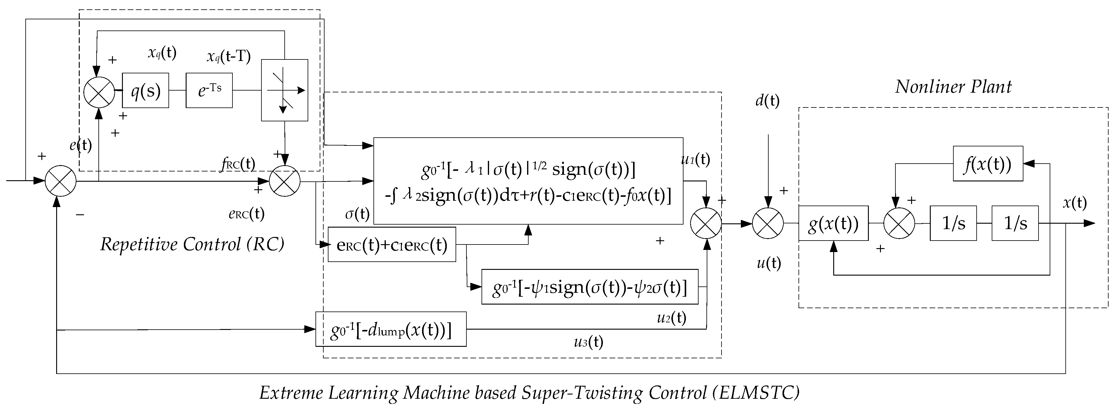
Chuei and Cao [
72] proposed an extreme learning machine-based super-twisting repetitive control (ELMSTRC), as shown in
Figure 12, to improve the performance of tracking periodic signals as well as to compensate for viscous friction and nonlinear friction. First, repetitive control was designed to track a periodic reference and compensate for viscous friction. Subsequently, a stable extreme learning machine learning-based hypertension control was constructed to compensate for aperiodic perturbations, nonlinear friction, clearances, and parameter uncertainties. Comparative studies showed that the proposed ELMSTRC exhibited excellent performance in tracking periodic signals, aperiodic disturbance compensation, friction compensation, clearance compensation, and robustness against system uncertainties.
Guo et al. [
73] proposed a new generalized clearance model that considered both nonlinear perturbations and unidentifiable couplings, which captured the actual clearance properties more accurately. An adaptive compensation control structure and a new smooth clearance inverse model, based on comprehensive neural network learning, were proposed, as shown in
Figure 13. An adaptive neural controller combined with a novel gap model was proposed to guarantee that all the signals of the closed-loop system were bounded and that the tracking error gradually converged to zero residuals. The simulation results verified the effectiveness of the proposed control scheme.
Prior knowledge of the clearance model on which the adaptive control is based is limited. After online identification and control, the system gradually adapts and adjusts to a satisfactory state. However, owing to the need for online adjustment, the operation is complicated, design difficulty increases, and cost increases.
4.2.3. Active Disturbance Rejection Control Method
The active disturbance rejection controller consists of three parts: tracking differentiator, extended state observer, and nonlinear feedback control law. The use of active disturbance rejection control to compensate for the clearance uses the extended state observer to estimate the disturbance caused by the clearance and to compensate for estimated disturbance through the nonlinear feedback control law.
Ma et al. [
74] proposed a dual-loop control structure. The outer loop control adopts active disturbance rejection control to compensate for external disturbance, and the inner loop control adopts model predictive control to compensate for saturation and clearance dead zone characteristics of the input and output of the servo system to ensure that the servo system can accurately and quickly track the required angle.
Ahi and Haeri [
75] disclosed a linear active disturbance rejection control with fractional-order integration (FOI-LADRC), which inputs process control variables and applies disturbances to output signals, feeds back the output signals, and tunes the setpoint tracking controller and the ESO to remove interference from the output signal.
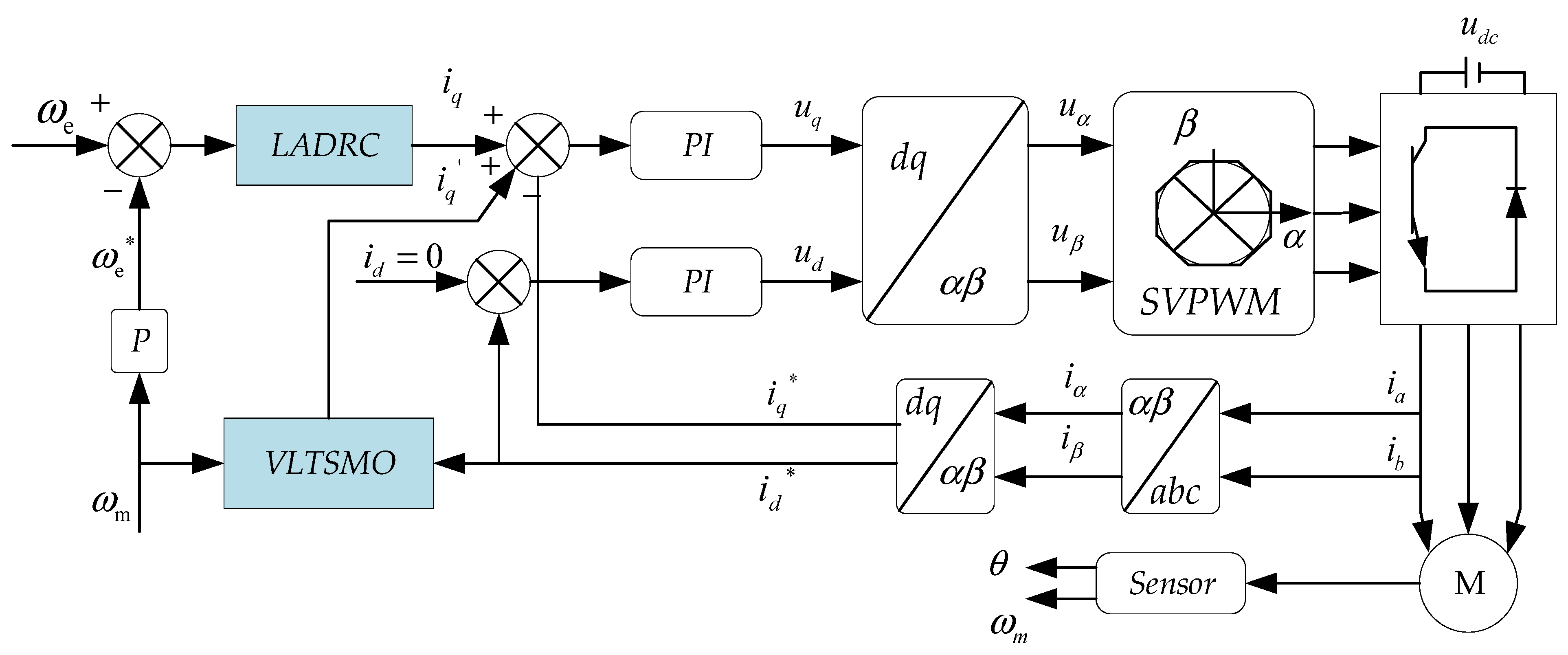
Zhang et al. [
76] proposed a linear active disturbance rejection control (LADRC) method with a variable gain load torque sliding mode observer (VLTSMO). The LADRC was used as the velocity loop controller, and a linear extended state observer (LESO) was used to observe the total disturbance. A block diagram is shown in
Figure 14. The proposed VLTSMO could output a feedforward compensation signal to improve the observer’s observation ability. The simulation and experimental results showed that the control strategy could effectively improve the dynamic performance and stability of the speed control system.
Wang et al. [
77] designed a quality adaptive control method, as shown in
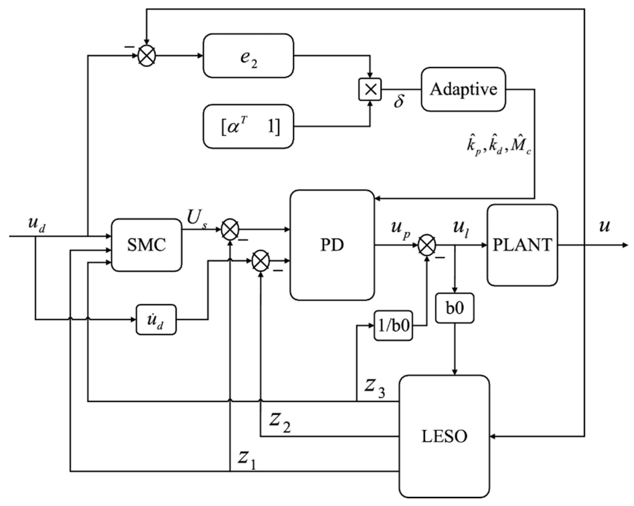
Figure 15, which combines robust sliding mode control (SMC) and linear active disturbance rejection control (LADRC). First, a mass-adaptive law was designed to remove the effects of mass variation. Second, SMC could enhance the robustness of the controller, improve the anti-jamming performance, and overcome the problem of low control accuracy caused by the bandwidth limitation of the LADRC. Third, to simplify the parameter setting, adaptive control was introduced in the LADRC, and the controller parameters were adjusted in real-time, which was beneficial to the stability analysis of the control system. The results showed that this scheme had less overshoot and a faster response, proving its superiority.
The advantage of the active disturbance rejection controller is that it does not depend on the clearance model, and the estimated total disturbance has great significance in improving the control performance of the actual system, which is suitable for engineering.
5. Discussion
In the compensation strategy for clearance, the mechanical anti-clearance method strives to reduce the clearance value from the physical space to suppress its negative influence. In this way, system performance can often be improved, but the cost of structural design and adjustment will increase significantly. Moreover, compared with the compensation of the control strategy, the mechanical clearance reduction method reduces the mechanical clearance in space, but the elastic connection of the transmission and other problems still exist. Therefore, the mechanical clearance reduction method has limitations in improving the overall performance of the system. The control compensation strategy involves designing the controller based on the clearance characteristic, exerting an effect from the control point of view, or considering its influence as a disturbance. These methods have characteristics for realizing the idea of suppressing the adverse effects of clearance. In practical applications, the difficulties of implementation and cost control should be comprehensively considered.
The adjustment methods of feedforward compensation control and inverse model control are both responsible for the disturbance effect. Disturbance observation control can overcome this shortcoming, but the introduced differential link is difficult to offset. Based on switching control, it is necessary to consider the smoothness and continuity of the transition as much as possible, thereby increasing the complexity of the control strategy. The control strategy based on the clearance model often relies excessively on the accuracy of the model, and the model-free control strategy can effectively avoid this shortcoming. Robust control is difficult in the face of nonlinearity. Adaptive control can effectively reduce the amount of control calculation, but it relies excessively on online adjustment. Active disturbance rejection control is completely independent of the clearance model, and can maintain good control performance by observing the total disturbance. In practical engineering, a control strategy can be comprehensively selected based on the design cost and control requirements.
According to
Table 2, combined with actual engineering problems, the comprehensive selection of the clearance compensation control strategy is carried out.
6. Conclusions
In recent years, increasing attention has been paid to the effect of clearance nonlinearity on servo systems. In-depth research on the cause and control of clearance can improve the performance of the system and eliminate the negative impact of clearance by selecting an appropriate method. This article discusses the negative effects of clearances on the system, such as mechanical resonance and loss of positioning accuracy. The control strategies of the servo system are introduced, which are mainly divided into control strategies based on the clearance model and model-free control strategies, and the advantages and limitations of these methods are analyzed.
Based on summarizing the relevant results, combined with the current control strategy and mechanical structure, the author believes that the future nonlinear control strategy of the clearance can focus osn the following issues:
Improvement of the mechanical structure increases the processing and manufacturing costs, optimization of the control strategy increases time complexity, and the control system design increases difficulty. Therefore, in the field of mechanical engineering, considering the energy savings of the control strategy is also the focus of follow-up research.
Accurate clearance models require inactive control methods, such as feedforward compensation and inverse model compensation. For complex nonlinear structures, such as servo systems, traditional kinematic modeling and parameter identification methods cannot obtain accurate models. However, the meta heuristic algorithm widely used in recent years has a strong nonlinear fitting ability; therefore, an identification strategy, combined with a novel and efficient intelligent algorithm, could be studied to accurately model the nonlinear clearance factor.
In a clearance control system, the selection of the control feedback signal affects the stability of the system, and the traditional control method typically adopts a single feedback signal. However, multi-source data, such as displacement, velocity, acceleration response signals, and excitation force signals of multiple points can be used as control feedback signals. Multi-source data have different characteristics, and a single feedback signal cannot fully utilize the multi-source information of the system. Therefore, research on the control method of fusing multi-source nonlinear data as a feedback signal will also become a potential means to improve the performance of the clearance control system.
Through the improvement and development of the clearance nonlinear control theory in the future, it is expected that ideas and solutions will be provided to solve the problem of poor performance of the servo system owing to clearance factors.


 .
. .
.