1. Introduction
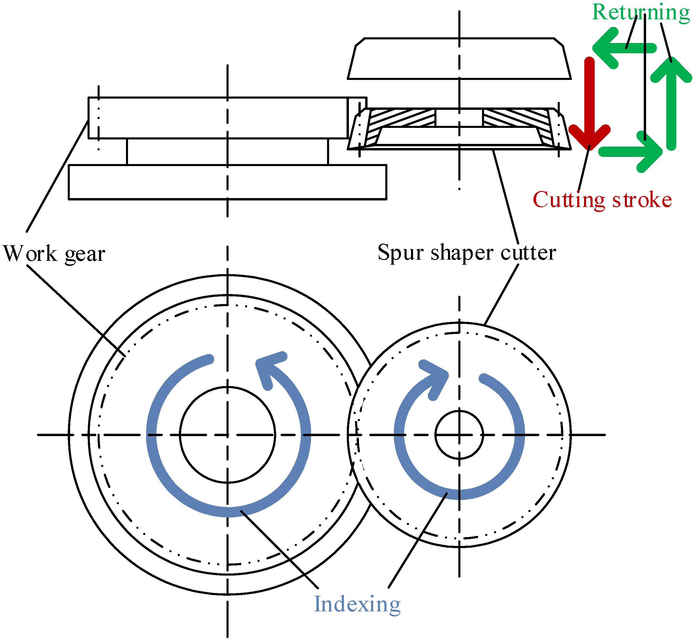
Gear shaping is a process that has been widely used for decay and is well developed, especially in fields where it is difficult to achieve results by hobbing, such as manufacturing internal gears and stack gears. A spur gear shaping cutter is a disk-type gear cutting tool that resembles a spur gear in appearance. As shown in
Figure 1, the gear shaping cycle comprises the cutting stroke, the returning motion and the indexing motion. The cutting stroke of the spur gear shaping cutter is a linear motion along the cutter’s axis, and its cutting edge forms a cutter enveloping gear [
1] during the cutting stroke. To provide appropriate cutting angles for proper cutting conditions, such as the side clearance angle and rake angle, profile shifting along the face width is necessary. Profile shifting also makes the cutter reusable after resharpening. Therefore, the shaping cutter’s parameter needs to be modified on the basis of geometric analysis [
1]. Although the modified pressure angle of the cutter enveloping gear is geometrically correct, the curvature of the profile at the pitch circle is slightly incorrect due to the side clearance and rake angles.
A shaping cutter is a versatile way to manufacture gears, such as external gears, internal gears and noncircular gears. Its most common application is in manufacturing spur gears. In the past decades, related studies on shaping cutters include those of Mobie et al. [
2,
3], who developed models for determining cutter offsets to produce nonstandard gears based on equal tooth strength and the method for designing spur gears with shaping cutters; Yoshi et al. [
4], who used a spur shaping cutter for finishing gears with arbitrary profiles; Kim and Kim [
5], who developed software to design shaping cutters; and Tsai et al. [
6], who developed models of spur gears generated by shaping cutters. In studies of elliptical gears manufactured by shaping cutters, Bair [
7] developed models for tooth profile generation in elliptical gear manufacturing with shaping cutters and computerized the proposed model, Figliolini and Angeles [
8] synthesized elliptical gear generation using a shaping cutter, and Chang and Tsai [
9] proposed computerized models for noncircular gears, including the tooth profile and undercut analysis. In the studies of tooth strength and undercutting conditions, Kawalec and Wiktor [
10] proposed a model for analyzing the tooth root strength of spur and helical gears manufactured by shaping cutters, Svahn [
11] developed the criterion of the undercut condition for shaping gears and improved the undercutting by modifying the basic rack, and Katz et al. [
12,
13] developed a virtual model for gear shaping that included kinematics, cutter–workpiece engagement, force, elastic deformations and virtual gear metrology.
In addition, Huang and Fong studied helical shaping cutters [
14,
15,
16] based on the Isoform
® [
17] grinding method, which is focused on the profile correction of helical shaping cutters. In the case of helical shaping cutters, their profile error differs from that of the spur shaping cutters because of their cutter edge types, namely, the plat and the conical cutter faces, respectively. In this study, we modified the mathematical model of the original rack profile to a three-order curve to correct the profile error of a spur shaping cutter. The profile error was reduced by adjusting the second- and third-order coefficients. The results are illustrated as profile error curves that correspond to different resharpened cutter edges.
2. Mathematical Model of the Spur Shaping Cutter
As shown in
Figure 2, the Isoform
® [
17] shaping cutter grinding method is highly accurate and efficient; it also provides a longer cutter life. In the shaping cutter generation process, the grinding wheel reciprocates along the shaping cutter tooth width, and the cutter rocks from side to side against the reciprocating wheel.
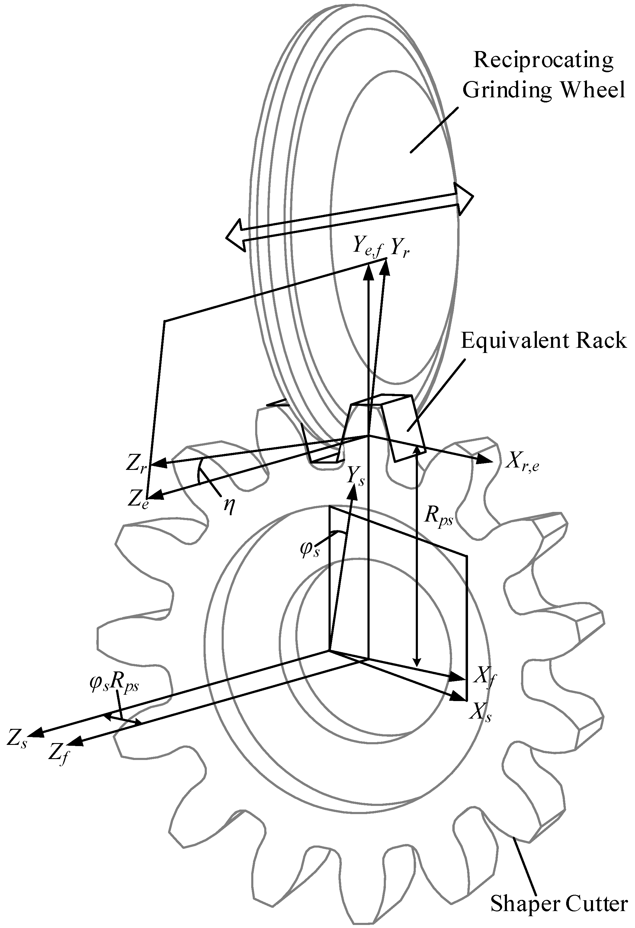
The reciprocating wheel can be considered as an equivalent rack cutter [
14,
15,
16]. The coordinated systems between the shaping cutter and the grinding wheel are shown in
Figure 3. Here, the equivalent rack cutter is inclined to the axis of the shaping cutter, which is used to shift the profile of the cutter tooth surface.
Figure 3 also shows the relative motion between the equivalent rack and the shaping cutter of an Isoform
® shaping cutter. The coordinate system
is that of the fixed coordinates, and the coordinate system
is rigidly attached to the shaping cutter and rocks from one side to another along the
axis;
and
are the rotating and shifting values during the generating motion along the
and
axes, respectively. Here,
is the pitch radius of the shaping cutter. The coordinate system
shifts
along
. Finally, the coordinate system
is rigidly attached to the equivalent rack formed by the reciprocating wheel. It also inclines
along
to shift the profile of the shaping cutter on the tooth surface.
The profile of the equivalent rack formed by the reciprocating grinding wheel is shown in
Figure 4. The coordinate system
is attached at the center of the equivalent rack space;
and
denote the surface variables in the profile and face-width directions on the rack’s surface, respectively; and
and
depict the tooth space and the normal pressure angle of the equivalent rack, respectively. The position vectors of the rack’s surface are shown in Equation (1) and the unit normal vector of the rack’s surface can be derived by Equation (2), where
is the first three elements of
. Here, we show only a mathematical model of the right flank, since the left flank is similar. With the coordinate systems
,
,
and
shown in
Figure 3, the position vectors and unit normal vectors of the equivalent rack can be transformed into the coordinate system of the shaping cutter shown in Equations (3) and (4), respectively. In Equation (3),
is the transformation matrix from the equivalent rack coordinate
to the spur shaping cutter coordinate
. In Equation (4),
, the transformation matrix for the normal vectors is the upper-left 3 × 3 sub-matrix of
.
where:
Moreover, to derive the tooth surface of the spur shaping cutter, we need the equation of meshing [
18,
19,
20] shown in Equation (5), where
depicts the first three elements of
. Solving Equations (3) and (5) simultaneously can produce the tooth surface of the shaping cutter.
4. Profile Error Analysis and Correction
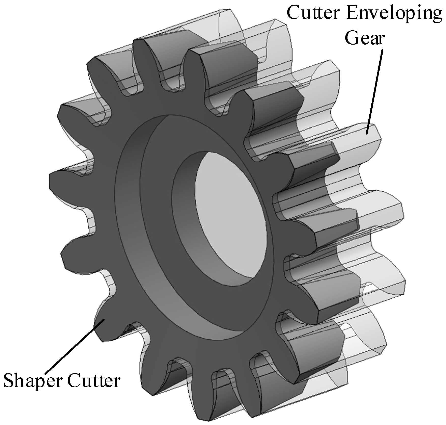
In shaping strokes, the cutter edge sweeps the gear surface of the cutter enveloping gear [
1,
14,
15,
16] in space, as shown in
Figure 6. The profile of the cutter enveloping gear directly governs the workpiece. Therefore, instead of the cutter edge, the profile of the cutter enveloping gear will be used to determine the profile error of the cutter. The flank of the cutter enveloping gear can be considered as the cutter edge projected on the transverse plane of the spur shaping cutter. Thus,
and
, which are the respective X- and Y-components of the cutter edge, can be used to determine the profile error. Moreover, in
Figure 5,
depicts the position corresponding to various resharpened cutter faces. Therefore, by changing
and then deriving the corresponding
and
using the proposed model, the profile of the cutter enveloping gear corresponding to different resharpened cutter faces is derived.
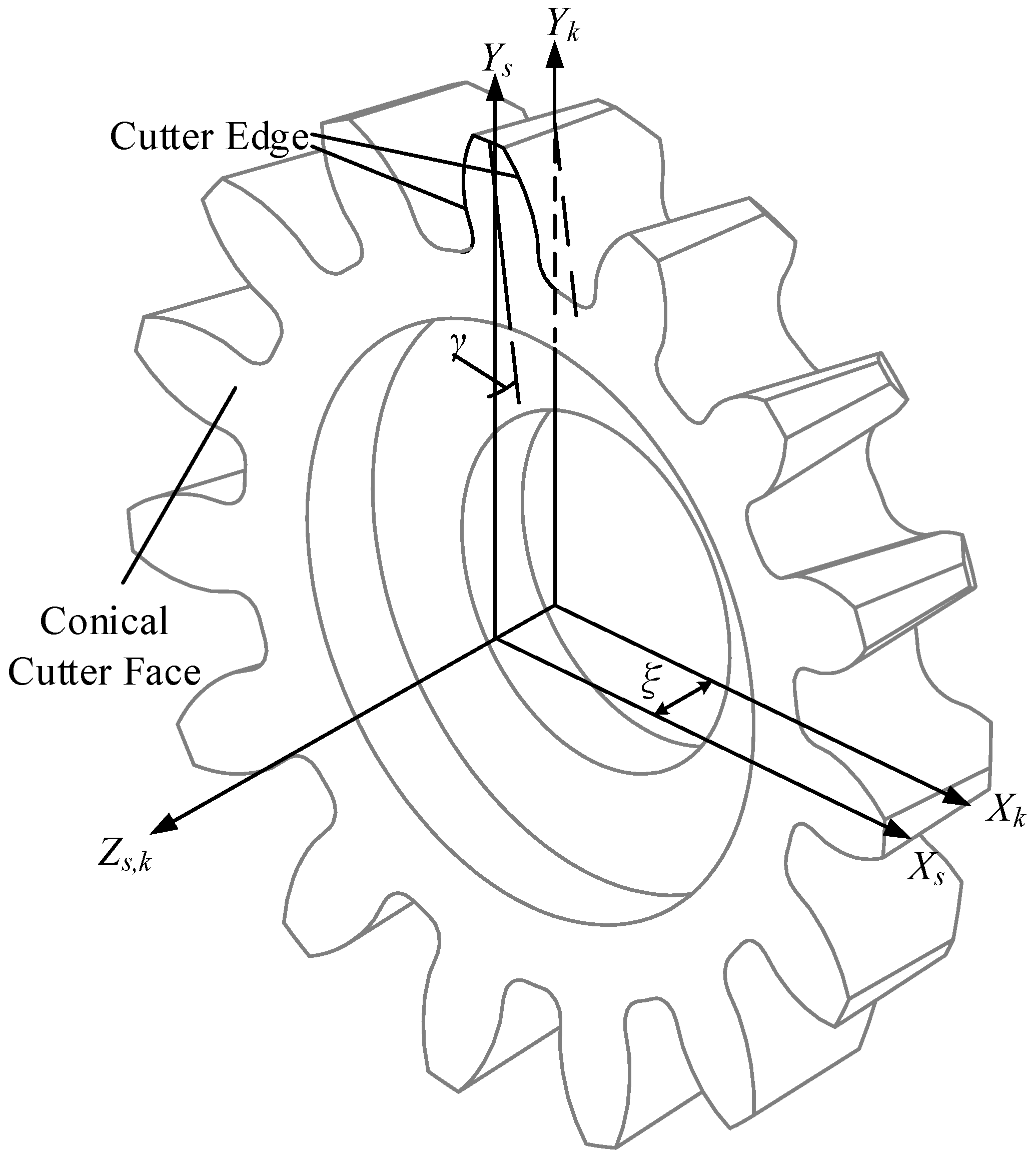
The spur shaping cutter has a conical cutter face, and the pressure angle of the equivalent rack can be modified by the corresponding geometrical relationships shown below. In
Figure 7,
shows the desired side clearance angle of the cutter. The side clearance angle
relates to the rack cutter pressure angle
and the required rack tilting angle
shown in Equation (8). In addition, the desired cutter pressure angle
related to the required rack tilting angle
and the required rack pressure angle
are shown in Equation (9). The required parameters
and
can be derived by solving Equations (8) and (9) simultaneously, which results in Equations (10) and (11), respectively. Note that the determination of the geometrical relationship of the cutter angle was derived in earlier studies [
1,
14].
The profile error of the spur shaping cutter is different from that of the helical shaping cutter because of the difference in the cutter face types. For the helical cutter, even after geometrical modification, the pressure angle is slightly different from what is desired. However, for the spur shaping cutter, the pressure angle of the cutter is correct after geometrical modification. It contains only the curvature and the higher-order curve errors caused by the side clearance angle and rake angle. To reduce the profile of the shaping cutter, the cutter flank of the equivalent rack is replaced by a curve and is related to the coordinate system
shown in
Figure 8. In Equation (12),
depicts the tooth surface of the rack cutter for correcting the cutter profile error, with
and
as the surface variables. The X- and Y-components of the tooth profile are likewise related in Equation (12). Here,
and
are the second- and third-order coefficients of the curve. Therefore,
can be used to control the curvature of the curve at the pitch circle, while
can be used to adjust the third-order curve form. Moreover,
is the mathematical model of the rack cutter used to correct the shaping cutter, which is obtained by Equation (13). In Equation (13),
is the transformation matrix between the coordinate systems
and
. We substitute
with
and re-derive all the corresponding mathematical models, then correct the curvature error by solving
and adjusting
to reduce the profile error even more.
To determine the profile error, the following models should be determined.
Figure 9 shows the geometrical model for calculating the error between the actual profile and the theoretical involute. In
Figure 9,
is the coordinate system of an actual profile and the
axis passes through the intersection of the actual profile and the pitch circle. Here,
is a certain point on the actual profile and
is the tangent point from
to the base circle. To calculate the profile error corresponding to the theoretical involute, the latter passes through the intersection of the pitch circle and the
axis, which causes the profile error at the pitch circle to be zero.
is the corresponding point on the theoretical involute, which starts at
on the base circle. The profile error
can be determined by
. Here,
can be derived by Equation (14), where
is the radius of the base circle and
can be derived by Equation (15), where
is the rolling angle of the involute at
. Moreover,
can be derived by Equation (16), where
depicts the value of the involute function obtained by the pressure angle
;
can be derived by Equation (17), which is the characteristic of the involute.
5. Examples and Discussion
In this section, a numerical example is used to verify the proposed mathematical models for correcting the profile error of the shaping cutter edge. The profile error of each cutter edge varies due to the profile shifting effect caused by the side clearance angle. Here, we used the cutter face at as the major cutter face to correct the profile, in which the profile error of its cutter enveloping gear was reduced to approach zero as much as possible.
The profile error of the cutter edge increases with the number of modules. Normally, internal gears are mostly below Module 3; however, for external gears, Module 4 (or larger) is commonly used. Therefore, as a compromise, we chose DP 7, which is equal to Module 3.6286 mm, as the module of the numerical example.
Table 1 shows the design parameters of the numerical example. In
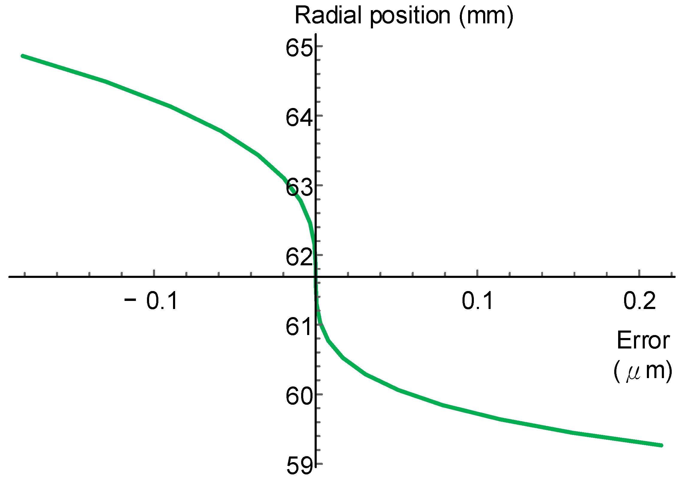
Table 1, the cutter parameters are the basic parameter (similar to the spur gear data) and its desired cutting angles; the equivalent rack parameters can be derived using Equations (10) and (11), and the tooth space was chosen as the standard tooth thickness (without profile shifting). The profile error of the uncorrected case is shown in
Figure 10. In
Figure 10, the error curve is tangential to the
Y-axis at the radial positions of the pitch circle, which shows that the pressure angle of the cutter enveloping gear is correct. The maximum profile error of this case is 4.8 μm.
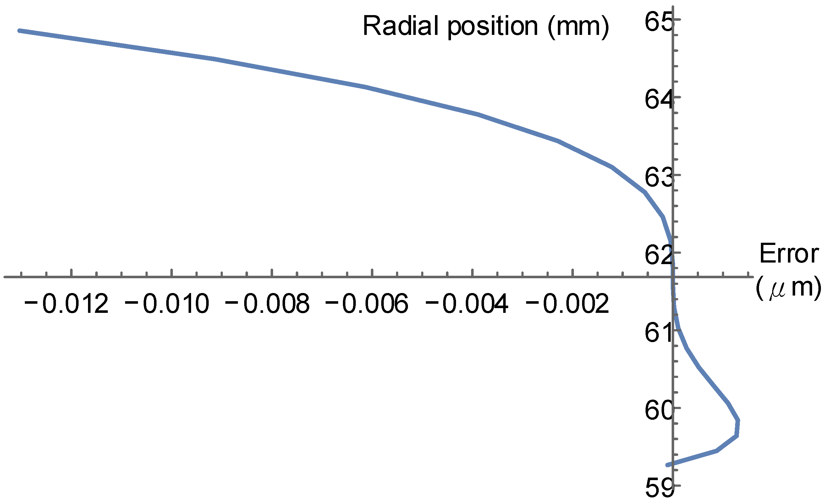
The first step for correction is to correct the curvature at the pitch circle, which can be obtained by
. The result is shown in
Figure 11. In
Figure 11, the profile error near the pitch circle is relatively small, and the profile error is within the sub-micron scale. The maximum profile error is 0.2 μm in this case.
Finally, to reduce the profile error further, we chose
. The result is shown in
Figure 12. In this case, the maximum profile error is about 0.01 μm, which is usually less than the minimum resolution of a typical gear measuring machine.
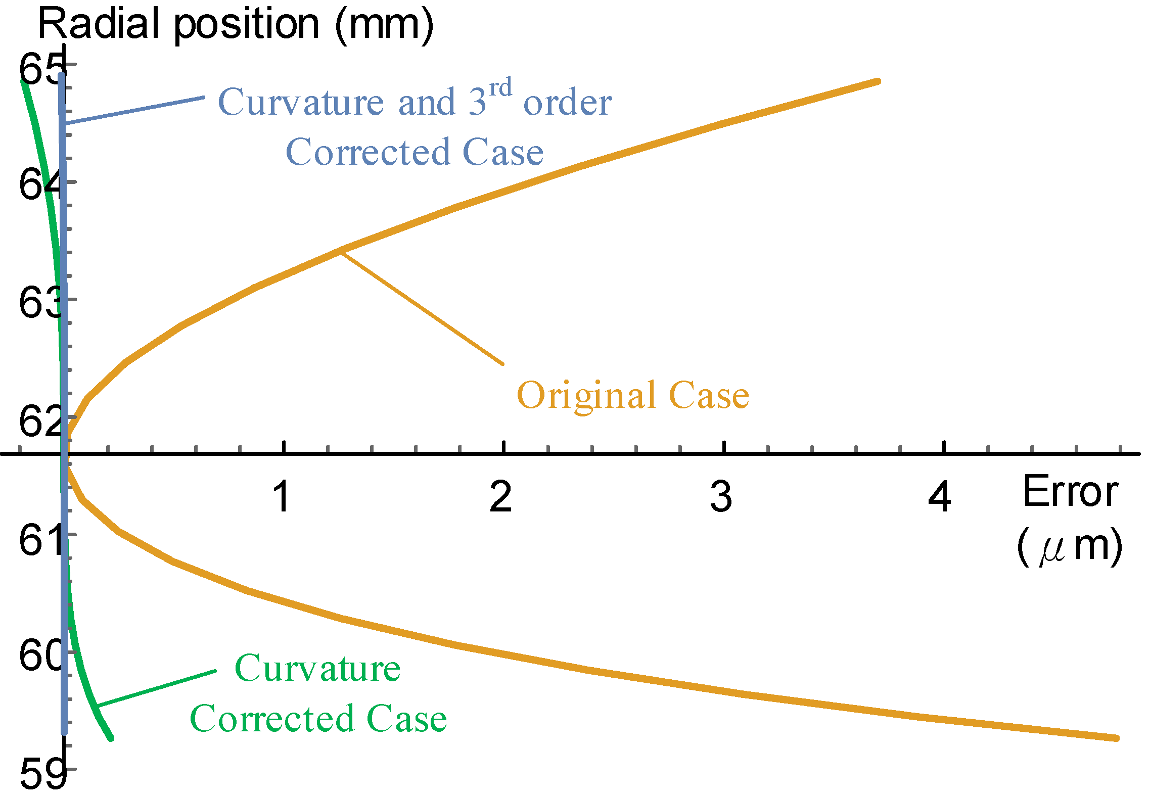
Figure 13 shows the effects of the proposed model of reducing the profile error step by step on the major cutter edge.
The result of the corrected case of the major cutter face approaches zero. To verify the effects of the proposed correcting model on other resharpened cutter faces with positive profile shifting, the results of the corrected and noncorrected cases with the cutter faces
and
are shown in
Figure 14 and
Figure 15, respectively. As the results show, after correction, the cutter edges of the shaping cutter perform more accurately in terms of the pressure angle error and form error for positive profile shifting cases.
Figure 16 and
Figure 17 show the results of the cutter faces
and
, respectively. In cases of negative profile shifting, after correcting the cutter edge, the shaping cutter still has better form accuracy. For the case of
, the pressure angle error of the uncorrected case performs better than that of the corrected case. However,
is close to the end of the cutter’s life.
As the results show in
Figure 11,
Figure 12,
Figure 13,
Figure 14 and
Figure 15, for the corrected cutter edges, the tilt of the profile error from one side to another corresponds to positive and negative profile shifting. The profile accuracy of the resharpened cutter edges is listed in
Table 2 and
Table 3, where it is easy to identify the accuracy variations corresponding to the resharpened cutter edges with respect to the original and corrected cases.


