Article

Numerical Simulation on Windage Power Loss of High-Speed Spur Gear with Baffles

College of Mechanical and Electrical Engineering, Nanjing University of Aeronautics and Astronautics, Nanjing 210016, China
*
Author to whom correspondence should be addressed.
Machines 2022, 10(6), 416; https://doi.org/10.3390/machines10060416
Submission received: 21 April 2022 / Revised: 18 May 2022 / Accepted: 24 May 2022 / Published: 25 May 2022
(This article belongs to the Section Machine Design and Theory)

Abstract

:
Windage power loss (WPL) is significant and cannot be neglected in a study on transmission efficiency and reducing the energy consumption of high-speed gear. The influence mechanism of the baffle on the reduction of WPL needs to be further studied. Based on computational fluid dynamics (CFD) technology, this paper puts stress on analyzing the influence of axial and radial baffles on viscous and pressure effects in WPL and the influence of baffles with groove structures on reducing WPL. The numerical calculation model of windage torque considering the baffle’s regulation is established, and the calculation results of WPL with different baffle configurations are obtained. The results indicate that the radial baffle mainly reduces pressure loss, while power loss caused by the viscous effect is mainly affected by the axial baffle. The baffle with the smallest clearance achieves the most significant suppression effect on windage. On this basis, adding groove structures to a smooth baffle can have a positive or negative impact on reducing WPL, and the baffles with circular grooves can further promote the reduction of WPL by 8.2%, compared with smooth baffles. This paper provides a reference for the optimal design of baffles in engineering applications.

1. Introduction

The power losses in many designs of industrial gear are important. High-speed and high-efficiency transmission represents the development trends of gearboxes in the field of automotive and wind turbine systems. In high-power and high-speed applications, such as the gearbox exceeding 100 MW, the optimal-designed gearbox still has great power loss, up to 2 MW with its efficiency reaching 98% [1]. When the gear works at high speed, the WPL is a great waste of energy impacting system dynamics and power loss performance [2,3,4], so it is very important to study the windage characteristics of high-speed gears. Fluid resistance caused by a rotating gear will reduce efficiency, which belongs to load-independent loss. When the gear pitch line velocity reaches 100 m/s, the WPL becomes prominent in the total power loss [5]. Research shows that changing the motion of the flow by setting baffles around gears is an effective measure to regulate the windage. Therefore, the optimal design of baffles has become a vital part of the design of a high-speed gear transmission system.
The accurate value of WPL can be measured through the gear windage test. Daniele et al. [6] designed a set of test devices for measuring the WPL of a single spur gear, which showed a significant reduction in a low-pressure environment. Winfree et al. [7] designed two gear baffle test rigs to measure the windage power loss of a single high-speed bevel gear and the effect of different baffle configurations. From there, the baffle with optimum clearance and outlet hole is determined. Ruzek et al. [8,9] built a non-meshing gear pair test rig aimed at studying the WPL of high-speed gear pairs. The results indicated that the airflow generated by different parts will affect each other, and the total WPL is slightly less than the superposition result of the individual loss. Delgado et al. [10,11] measured the WPL of a meshing spur gear pair with baffles, under different pitch line velocities, obtaining the most obvious effect of the baffle at 76 m/s. The quasi-analytical formula of WPL can be obtained by calculating the fluid resistance at the gear end face and gear teeth. Zhu et al. [12] established a quasi-analytical model of the spiral bevel gear based on it. Pallas et al. [13] studied the volumetric flow rate expelled by the teeth and the calculation formula of WPL based on the volumetric flow rate and the geometrical is obtained. These test results show the source and influential factors of the windage effect. The motion of fluid between teeth greatly affects the windage power loss in the high-speed gear transmission system. However, the measurement of WPL is limited by the test equipment in which transmission components of the gearbox can affect each other. The WPL theoretical formulas of a spur gear or helical gear [14,15,16] obtained from the experiment are often limited to specific gear types or specific working conditions. By the CFD method, the main parts can be studied independently and the influence of baffles on losses caused by viscous effect and pressure effect can be obtained, respectively, which is beneficial in revealing the windage characteristics through flow field motion.
More recently, a numerical simulation model based on computational fluid dynamics has become an effective tool to study flow field characteristics and high-speed gear windage [17,18]. The computational expense can be greatly reduced by using the MRF approach [19], and the windage loss prediction model established by overset mesh strategy can also obtain credible results for the spur gear and spiral bevel gear [20,21]. The study of baffle structure by CFD is also effective, and the distribution of the flow field can be obtained. Fondelli et al. [22] pointed out that the windage loss is related to the volume of fluid around the gear by a simplified numerical model of the spur gear. Hill et al. [23] employed CFD to study the effect of different baffle arrangements on reducing WPL, and put forward several tooth-shaped design schemes that further reduce gear windage. In A He’s research [24], adding grooves to the inner wall of a radial baffle achieves a further reduction of WPL compared with the smooth baffle. Li et al. [25] and Dai et al. [26] studied the influence of baffle orientation and clearance on a helical gear and a face gear, respectively. Zhu et al. [27] and Zhang et al. [28] studied WPL of a spiral bevel gear with or without baffles, analyzed the effects of baffle clearance including the toe, the face, and the heel clearances, and obtained optimal baffle configuration. The numerical solution of the flow field by finite volume method can effectively analyze the phenomena of laminar and turbulence flow. However, the research on the influence of baffle structure parameters on WPL is still not comprehensive. It can be seen from previous studies that not all baffle configurations play a positive role in reducing WPL. The influence of grooved baffles on flow field motion and windage regulation needs to be further studied.
In summary, many studies have calculated the windage loss by means of experiments or numerical simulation and analyzed the regulation of gear baffles. The research cycle is long, however, and with high test costs, and the data obtained is limited. The flow field simulation by the CFD method is more intuitive, and the impact analysis of gear parameters on WPL is more convenient. Therefore, this paper also adopts the numerical solution of the high-speed flow field to study the windage characteristics.
In this paper, the CFD model of WPL prediction is established based on the dynamic mesh model and SST k-ω turbulence model, using FLUENT software. The WPL of a non-baffle gear configuration at different pitch line velocities of 60 m/s to 150 m/s is calculated, and the numerical results are verified by comparing the test data in the open literature. The flow field characteristics are analyzed, especially the volume flow between teeth, the viscous effect, and the pressure effect under different baffle configurations are compared. These flow field characteristics are difficult to obtain in previous experiments, but they can be well displayed in the form of a contour map or streamline. Furthermore, this paper focuses on the effect of baffle structure on WPL. The baffles under different clearances and the baffles with groove structures are designed to regulate windage torque and fluid motion. The effect of two kinds of groove structures (circular grooves and straight grooves) are emphatically analyzed, which is rarely seen in previous studies. These studies contribute to further extending researchers’ understanding of the characteristics of windage and the role of the baffle in reducing WPL.

2. Numerical Simulation Calculation Model

2.1. Governing Equation

When the gear rotates at high speed, the surrounding flow field also rotates with the gear and develops into turbulence. The flow field state is judged by the Reynolds number. The larger the Reynolds number, the more significant the inertial force influence, which means an unstable flow field and likely turbulent flow. The Reynolds number equation is:
Re = ρ v l μ
where ρ, v are the fluid density and fluid velocity, l is the characteristic length and μ is the dynamic viscosity.
The fluid flow in the present study belongs to turbulence, and the SST k-ω model, which is suitable for the hydrodynamic analysis of strong swirl flow with a high Reynolds number, will be adopted. The relationship is as follows:
t ( ρ k ) + x i ( ρ k w i ) = x j [ ( μ + μ t σ k ) k x j ] + P k β * ρ k ω + S k
t ( ρ ω ) + x i ( ρ ω w i ) = x j [ ( μ + μ t σ ω ) ω x j ] + α ω k P k β ρ ω 2 + 2 ( 1 F 1 ) ρ 1 ω σ ω 2 k x j ω x j + S ω
where α, β, β*, σk, and σω are constants; k denotes the turbulent kinetic energy; ω is the dissipation rate; Sk and Sω are the user-defined source items.
Meanwhile, the effect of temperature is not considered in this paper. The fluid flow obeys the law of mass conservation and the law of momentum conservation. The mass conservation equation and the momentum conservation equation are:
ρ t + ( ρ v ) = 0
( ρ v ) t + ( ρ v v ) = p + [ μ ( v + v T ) ] + ρ g + F
where ρ, v represent the fluid density and fluid velocity, respectively. μ is the viscosity, g is the gravity acceleration, and F is the vector of external forces.
The SIMPLE algorithm is applied to enforce mass conservation and obtain the pressure field using a relationship between velocity and pressure corrections. The momentum equation is solved with a guessed pressure field p*, and Equation (6) is used to solve the surface flux, which satisfies the continuity equation.
J f = J ^ f * + d f ( p c 0 * p c 1 * ) + d f ( p c 0 p c 1 )
where p’ is the cell pressure correction; J ^ f * contains the influence of velocities in cells.

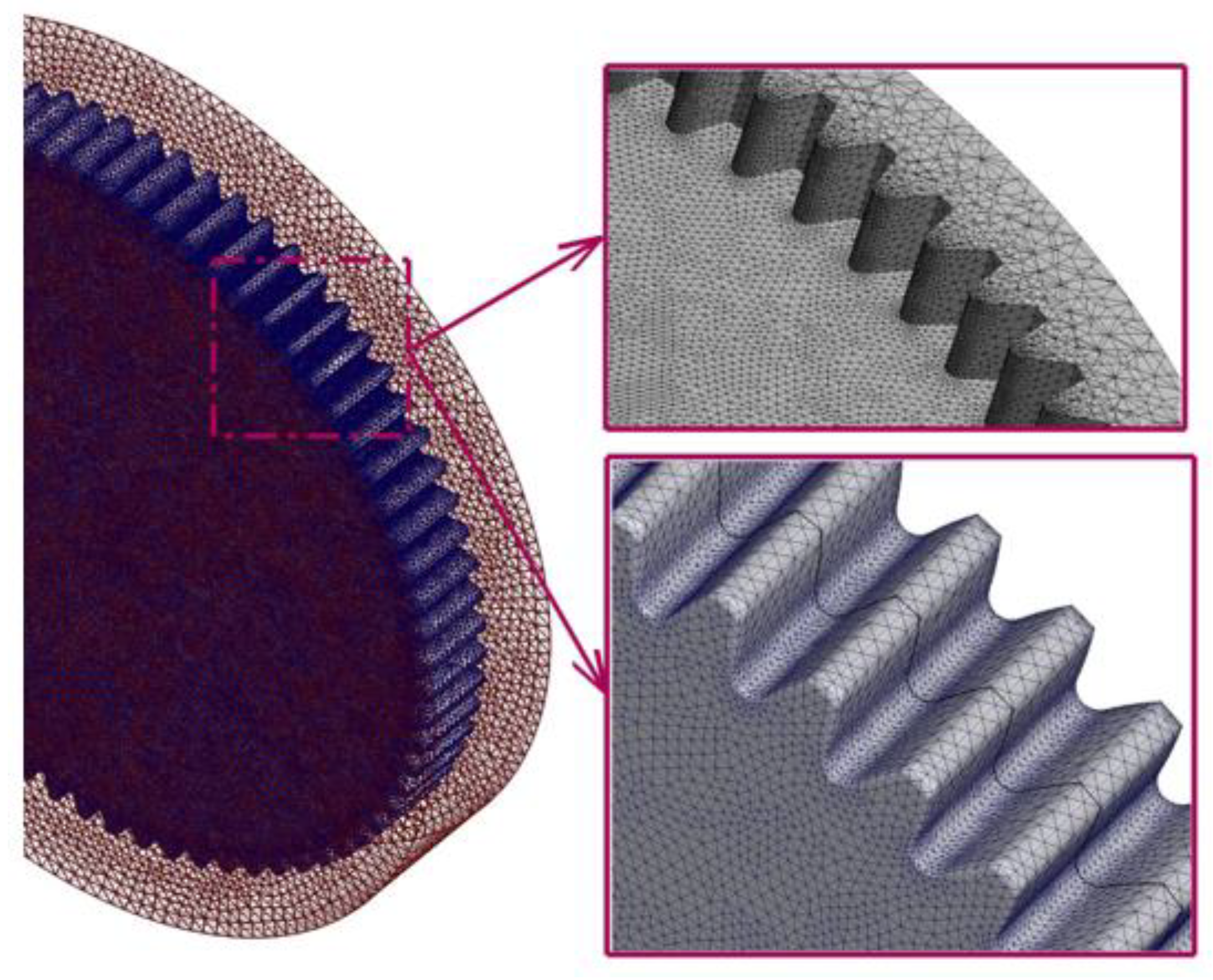
2.2. Dynamic Mesh Model

The dynamic mesh technique is used to simulate rigid boundary motion. Two mesh motion methods of smoothing and remeshing are used to update the volume mesh in the deforming regions subject to defined motion boundary.
The smoothing method is used to absorb the movement of the boundary while keeping the number of nodes unchanged. The edges between any two mesh nodes are idealized as an interconnected springs network. According to Hook’s Law, the force on a mesh node can be written as:
F i = j n i k i j ( Δ x j Δ x i )
where Δ x i and Δ x j are the displacements of node i and its neighbor j, ni is the number of neighboring nodes connected to nodes i, and kij is the spring constant between node i and j. The spring constant for the edge connecting nodes i and j is defined as:
k i j = k f a c | x i x j |
where kfac is the value for the spring constant factor.
The remeshing method is used to agglomerate cells that violate the skewness or size criteria and remesh these cells or faces. The mesh quality of local reconstruction is guaranteed and negative volume is avoided. In this paper, the maximum cell skewness is set to 0.7, and the minimum and maximum length scales are set to 0.000212 m and 0.019419 m, respectively.

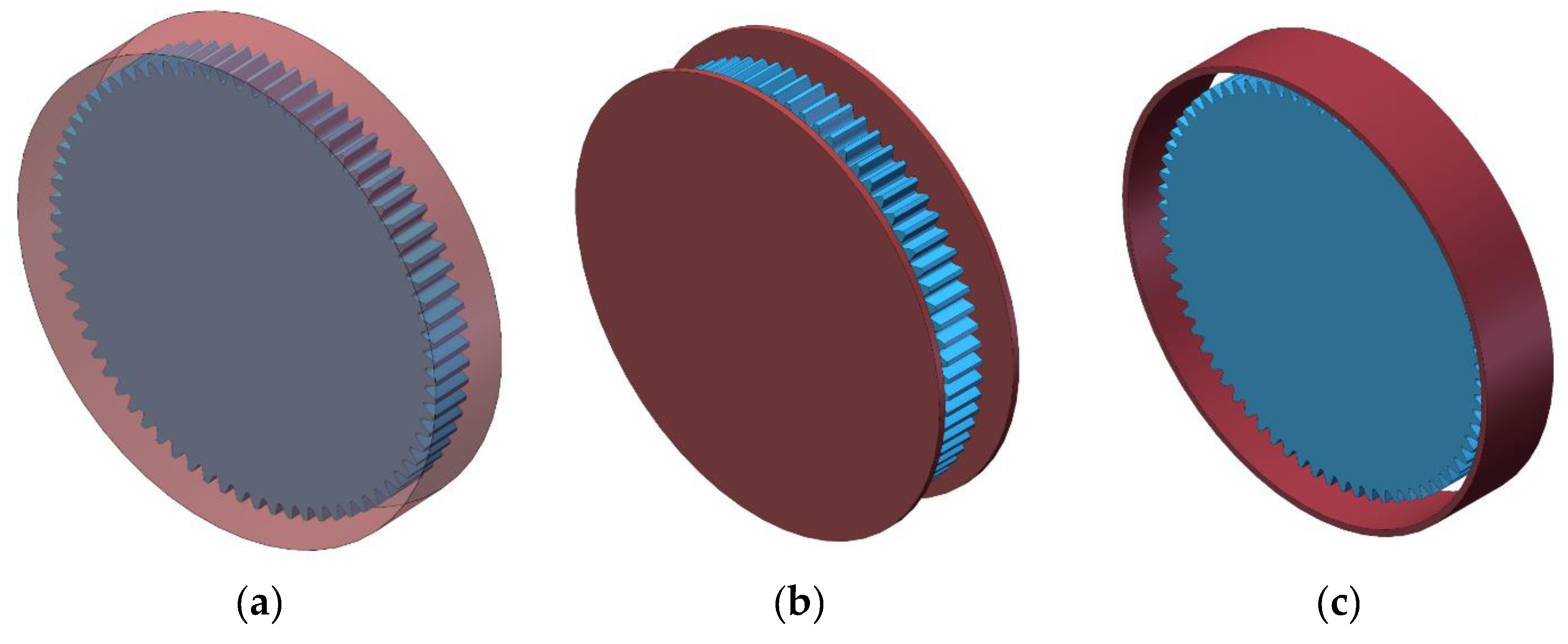
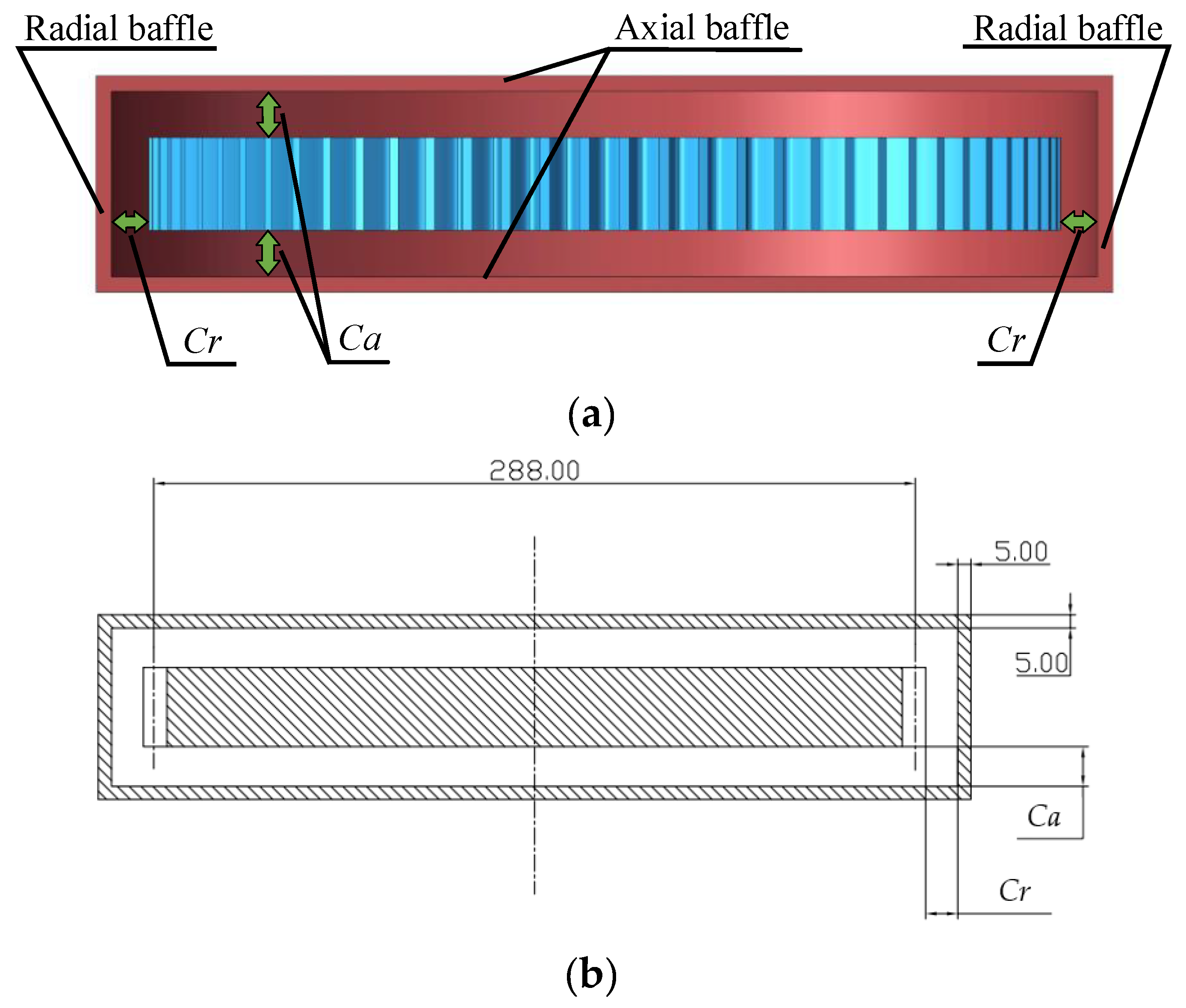
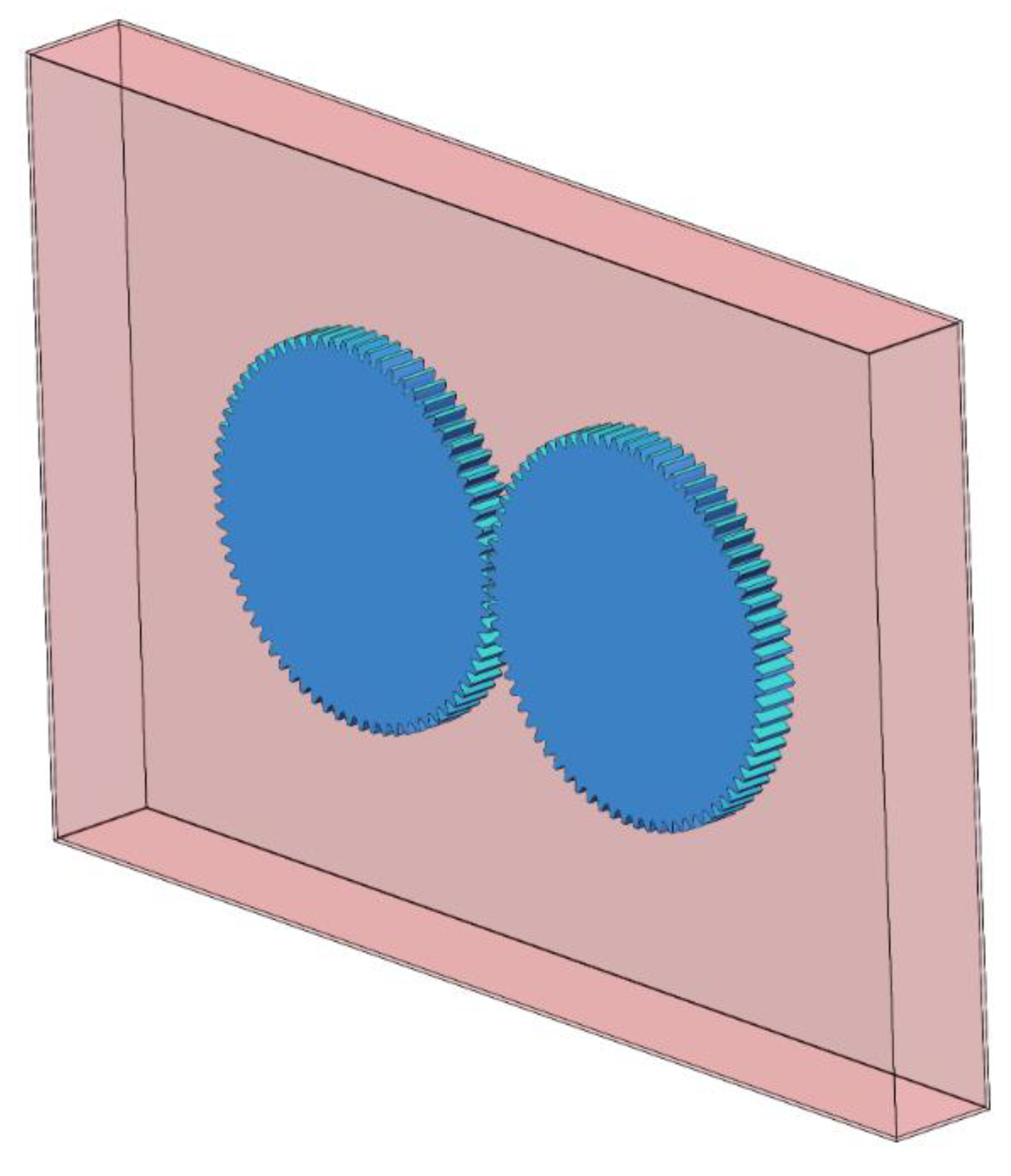
2.3. Computational Domain and Solution Settings

The basic parameters of the spur gear are shown in Table 1. In this paper, the windage characteristics of a single gear are studied, the effect of baffles on regulating the flow field is analyzed, while the effects of oil injection and tooth meshing are not considered, so the model will be further simplified. The research results of this paper will provide a theoretical basis for the study of WPL of gear pairs in an oil-gas two-phase flow field.
The computational domain of a spur gear obtained by Boolean operation is shown in Figure 1a, ignoring the shaft, bearing, etc. to simplify the numerical calculation. The gear surfaces are set as rotating walls, and their motions are defined by the dynamic mesh model. The axial baffle and radial baffle shown in Figure 1b,c are set as stationary wall boundaries, while they are set as opening boundaries in non-baffle cases. It should be noted that the influence of roughness is not considered in this paper. As shown in Figure 2, Ca and Cr represent the clearance between the baffle and the gear body in the end-face direction and tooth-tip direction, respectively. The effect of baffle clearance on WPL will be discussed in Section 3.2.
Unstructured tetrahedral mesh is used for the mesh generation of the computational domain. Considering the calculation accuracy and the amount of calculation, the grid cells near the tooth surface are refined. Capture Curvature and Capture Proximity are set to Yes, setting Curvature Normal Angle and Num Cells Across Gap to 18° and 4, respectively. These settings can refine mesh cells in the specified area according to the defined curvature and narrow gap. The average element quality is 0.83. The mesh shown in Figure 3 has good convergence and the mesh independence analysis is tested. The number of cells in the entire fluid domain is about 2.2 million, and the total number of nodes is about 0.4 million.
The fluid material of the computational domain is air and the density and viscosity are 1.225 kg/m3 and 1.7894 × 10⁻⁵ kg/(m·s). The influence of gravity is mentioned in this paper. On the condition of ensuring calculation convergence and accuracy, PRESTO and second-order upwind discrete format are adopted for pressure and momentum equation discretization, respectively. Meanwhile, the relaxation factor is appropriately reduced to increase the stability of the calculation. The time step is also set at the suitable value of 2 × 10⁻⁶. After the calculation, the WPL is calculated by the following formula:
P = ( T 1 + T 2 ) n π / 30
where T1, T2 represent the torque in the teeth surface and end surface, respectively, and n is the gear rotational speed.
In order to verify the applicability and practicability of the simulation model in predicting windage loss, the Numerical results based on the CFD method are compared with Dawson’s theoretical values. Dawson [14] gave a formula for calculating the WPL considering the sides and periphery of a spur gear, respectively, in his research. The formula is as follows:
P = N 2.9 ( 0.16 D 3.9 + D 2.9 F 0.75 M 1.15 ) × 10 20 φ λ
where P is windage power loss; N, D, F, and M are the rotational speed, the root diameter, the face width, and the tooth module, respectively; φ denotes the oil-gas mixing coefficient, and λ represents the enclosure coefficient.

3. Results and Discussion

3.1. Windage Power Loss of Non-Baffle Spur Gear

The high-speed rotation of the gear makes the surrounding flow field move at high speed, which will have a great impact on the WPL. The windage characteristics of the non-baffle gear are studied in this section, and the numerical results of WPL are compared with the theoretical results. The changes in volumetric flow rates in different directions between the gear teeth, with speed and the proportion of viscous and pressure loss, are mainly studied.
The fluid domain model of the gear pair with a transmission ratio of 1:1 is also established, as shown in Figure 4. Then the windage losses of a single gear and a gear pair are calculated respectively. Figure 5a illustrates the estimated values of WPL at different speeds. Compared with the open literature, the numerical results are in good agreement with the theoretical values [14]. It can be seen that with the increase in rotating speed, the WPL increases rapidly, reaching more than 5 kW at 150 m/s. The empirical formula proposed by Dawson fits the experimental data, and the test speed reached 80 m/s, so there will be a deviation at a higher speed. The numerical results and the theoretical results have almost the same change trend, and the maximum error is within 10%. In addition, the WPL of the gear pair is a little smaller than that of a single gear, because the fluid collides in the meshing zone with the rotation of the gear, which changes the fluid motion and reduces the resistance on the gear. However, this influence is limited, especially when the pitch velocity is more than 100 m/s, with an error of less than 5%.
It is noted that the windage torques caused by the pressure and the viscous effect (two parts of the WPL) are investigated. The percentage in Figure 5b represents the proportion of pressure effect, which, as the main part of WPL, accounts for nearly 90%. There is a slight increase in pressure loss from 87.86% to 90.41% at the speed from 60 m/s to 90 m/s, because of the weakening of the viscous effect at high speed. Above 90 m/s, the proportion of pressure loss does not show an obvious change. The pressure loss is caused by the pressure difference formed between the teeth when the gear rotates at high speed, so it mainly occurs at the gear teeth. The power loss caused by the viscosity between the fluid and the gear surface mainly occurs at the gear end faces. It can be seen that these two types of losses are closely related to the material and flow of fluid. Moreover, the proportion of the two types of losses is close in the simulation of a single gear and a pair of gears.
Figure 6a demonstrates the pressure distributions of pressure surfaces and suction surfaces on the opposite teeth surfaces, which are caused by the inflow and outflow of fluid between the teeth. The maximum positive pressure reaches 5.6 × 10³ Pa and the maximum negative pressure reaches −2.8 × 10³ Pa; obvious near the end face of the gear. As shown in Figure 6b, compared with the simulation of a single gear, the tooth surface pressure in the gear pair simulation shows a difference in the meshing area. The positive pressure is caused by the large collection and collision of fluid in the meshing-in area with the rotation of gears while the negative pressure in the meshing-out area is due to the reduction of fluid volume when the gears mesh out.
Figure 7a shows the fluid streamline between the teeth, which indicates the flow direction of the fluid. The fluid rotates with the gear, flows in from both ends of the gear (axial direction 1 and axial direction 2), and flows out from the tip of the gear (radial direction). The fluid rotates with the gear to obtain speed, forms resistance between the teeth, and consumes power. Therefore, the volumetric flow rate drawn or expelled between the teeth is an important factor to determine the WPL. Similar to the flow field pressure in Figure 5, in the simulation of a pair of gears, there is no significant change in the streamline in other areas, except that the fluid in the meshing area is greatly affected, as shown in Figure 7b. The volumetric flow rates from three directions shown in Figure 8 also prove the view expressed above. It can be observed from Figure 8 that the volumetric flow rates increase gradually with the rise in rotational speed. Through the above analysis, regulating the fluid flow by setting baffles around the gear will be an effective measure to reduce the WPL.

3.2. Windage Power Loss of Gear with Baffles

According to the windage characteristics analysis of the non-baffle gear, the WPL is closely related to the inflow and outflow of fluid between teeth. Adding baffles around the gear can hinder the movement of fluid, reduce the fluid flow between teeth, and achieve the reduction of the energy consumed by fluid acceleration. This section studies the influence of baffles on windage, including baffle orientations, baffle clearances, and baffles with groove structures. According to the analysis in Section 3.1, the flow field state of a pair of gears is similar to the simulation results of a single gear except in the meshing area. The WPL decreases slightly due to the change of flow field, but this influence is quite limited. Therefore, this paper uses the model of a single gear to study the WPL and the regulation of baffles, which can simplify the model and calculation.
In order to study the influence of gear baffles on WPL, simulation models with different baffle configurations are established. In Figure 9, the boundary type of baffle is Wall and the clearances between baffles and gear are set to 5 mm. The axial baffles and radial baffles are marked with blue lines and black lines, respectively. The non-baffle boundaries are set as open boundaries named “Opening” in Figure 9, and the inflow and outflow of fluid depend on the pressure difference.
Figure 10 shows the WPL curves for different baffle configurations. The results show that both radial baffle and axial baffle can restrain windage, reducing WPL by 44% and 22%, respectively. Obviously, the regulation effect of the radial baffle is better than that of the axial baffle. In Baffle configuration 4, the combined baffle has the best effect and can reduce the WPL to about 16% with a total power loss under 800 W.
In the flow field without baffle, as shown in Figure 11a, the fluid flows into the teeth from the end faces on both sides of the gear, rotates with the gear and obtains a high speed, and then flows out from the middle of the tooth top, forming several vortices above the gear. The radial baffle configuration in Figure 11b blocks the inflow or outflow of fluid from the tooth top. The fluid flow between teeth decreases and vortices are formed between teeth. The axial baffle configuration in Figure 11c affects the fluid motion of the end faces, forcing the fluid to enter between the teeth from one end of the tooth top, and then flow out from the other end. The combined baffle configuration limits the fluid movement to the greatest extent, as shown in Figure 11d. The decrease in fluid flow results in a reduction of power loss due to fluid acceleration. By comparing the flow field distribution of different baffle configurations, it can be seen that: (1) During the high-speed rotation of the gear, the wind resistance loss of the gear mainly comes from the gear teeth, not the gear end-face. The gear teeth drive the fluid around them and form a strong air vortex between the gear teeth and the top of the gear; (2) The existence of the gear baffle reduces the streamline density near the gear and decreases the fluid velocity, thus reducing the increased air kinetic energy, which is transformed from the energy lost by the gear; (3) The baffle limits the action range of the gear on the surrounding fluid, which reduces the formation range of the vortex and makes the turbulent motion milder.
Figure 12 shows the proportion of WPL caused by pressure and viscous effect and the percentage is the average proportion of the loss resulting from the pressure under one configuration. As depicted in Figure 11, the percentage of Configuration 2 decreases by 8.28% compared with Configuration 1, while the percentage of Configuration 3 shows a slight increase by 2.93% compared with Configuration 1. It can be inferred that the pressure loss mainly occurring at the gear teeth is affected by the radial baffle, while the axial baffle mainly reduces the power loss caused by the viscous effect which mainly occurs at the gear end-faces. In addition, both types of power loss are greatly reduced in Configuration 4, and the proportion of pressure loss is more affected. It can be concluded that the reduction of pressure loss by the radial baffle predominates in the regulation of the windage effect.
To further analyze the effects of baffles, this paper sets baffle configurations with different axial clearances and radial clearances, as shown in Table 2, where Ca is axial clearance and Cr is radial clearance. The axial clearance is Ca = 5 mm, 10 mm, and 15 mm, respectively, and the radial clearance is Cr = 5 mm, 10 mm, and 15 mm, respectively. Figure 13 illustrates the WPL under different baffle configurations of radial clearance and axial clearance. According to Figure 13, the minimum clearance shows the best performance to reduce the WPL in a certain range. The difference between the numerical results of different radial clearances is smaller than that of different axial clearances. Therefore, small clearance should be selected as far as possible when selecting the axial baffle.
To explore the influence of baffles with groove structures on the WPL, groove structures are added to smooth baffles. Figure 14a shows the straight grooves (Configuration 9) and circular grooves (Configuration 10) on the axial baffle. The engineering drawing is shown in Figure 14b. The width of the groove is 1 mm and the depth of the groove is 1 mm. Figure 14c shows the straight grooves (Configuration 11) and circular grooves (Configuration 12) on the radial baffle. The engineering drawing is shown in Figure 14d. The width of the groove is 2 mm and the depth of the groove is 2 mm. It should be noted that the axial baffle only adds grooves near the gear teeth in this paper.
Figure 15 shows the WPL results of baffles with straight grooves and baffles with circular grooves, respectively. It can be seen that Configuration 10 and Configuration 12 have a further reduction of WPL, which is 8.2% lower on average than that of the smooth baffle. However, the power losses of the other two configurations with straight groove baffles increase. Thus, the groove structures on the baffles have an impact on the windage. The circular groove structure will promote the reduction of WPL, while the straight groove will greatly weaken the effect of the baffle.

4. Conclusions

In this paper, the influence of different baffle configurations on the WPL of a high-speed gear is investigated. The WPL prediction model of a single spur gear is successfully established by the CFD method. The influence of axial and radial baffles, different baffle clearances, and different groove structures on WPL is analyzed. The main conclusions are as follows:
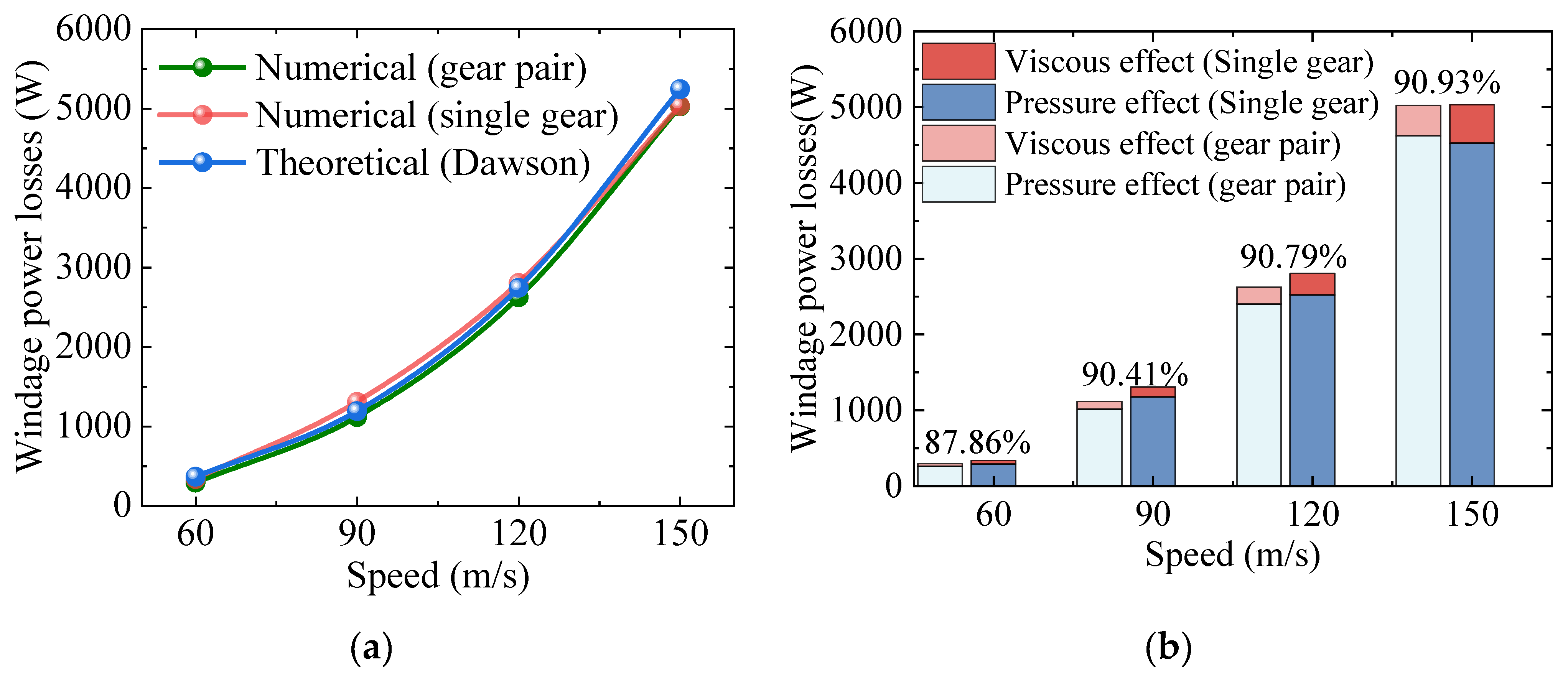
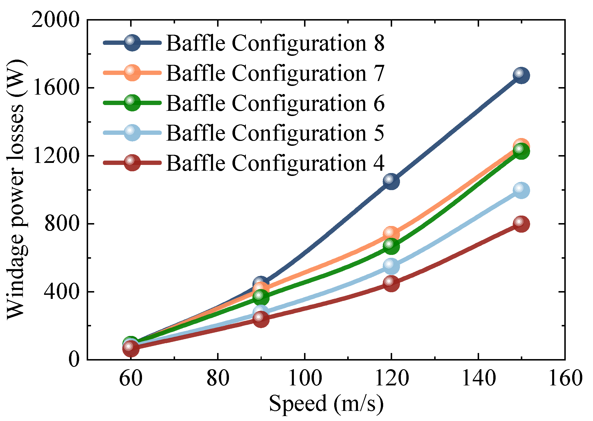
  • The numerical calculation results of WPL are in good agreement with Dawson’s theoretical calculation results, with an average error of 6%. The reliability of the dynamic mesh method and models is proved. With the increase in pitch velocity, the WPL increases rapidly and reaches more than 5 kW at 150 m/s, which is much higher than at low speed. Thus, it is important to accurately calculate the WPL of the high-speed gears.
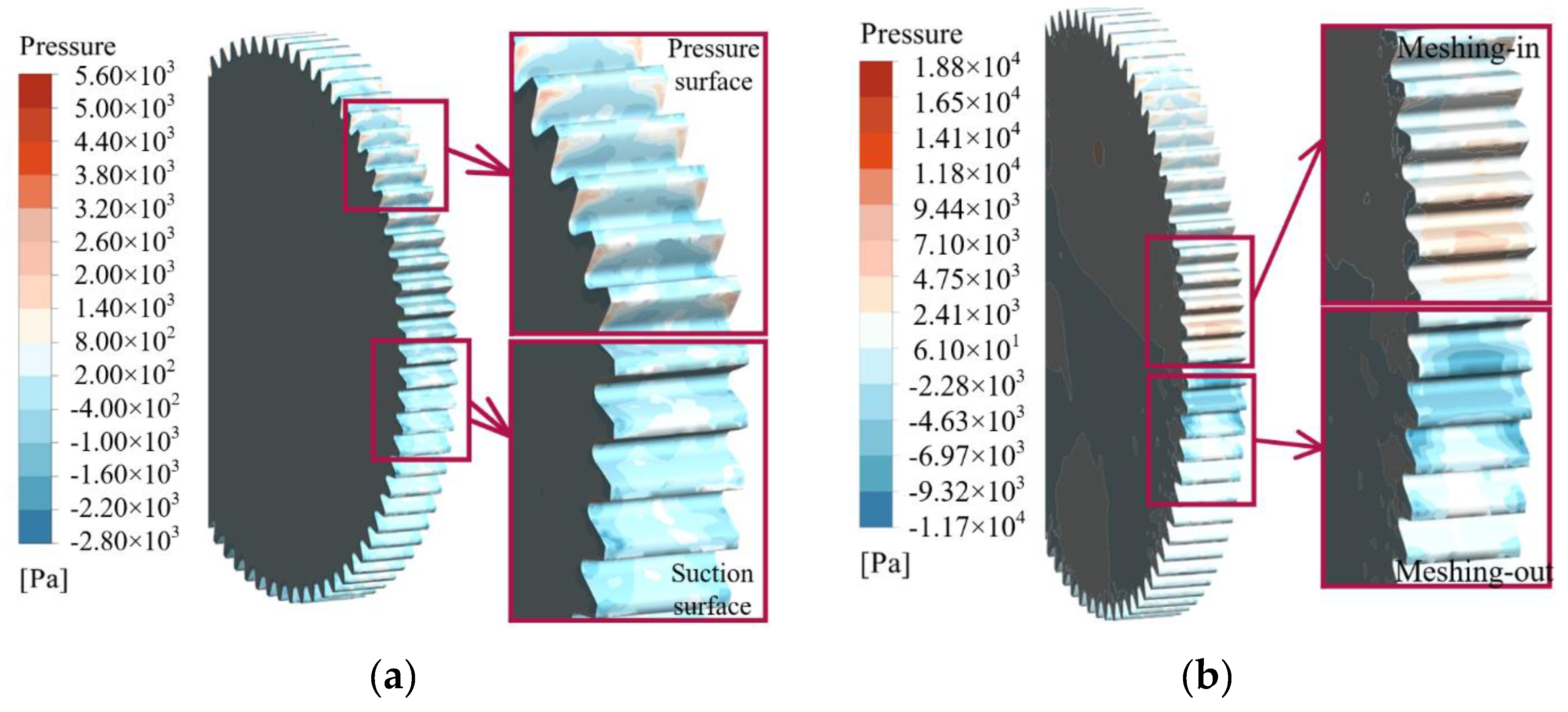
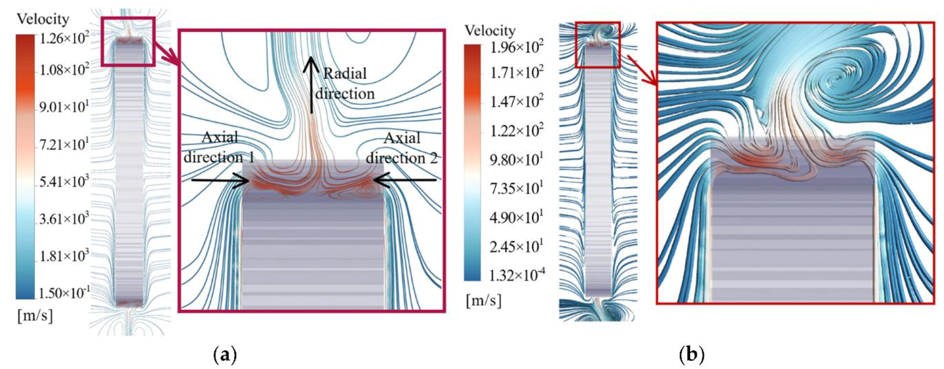
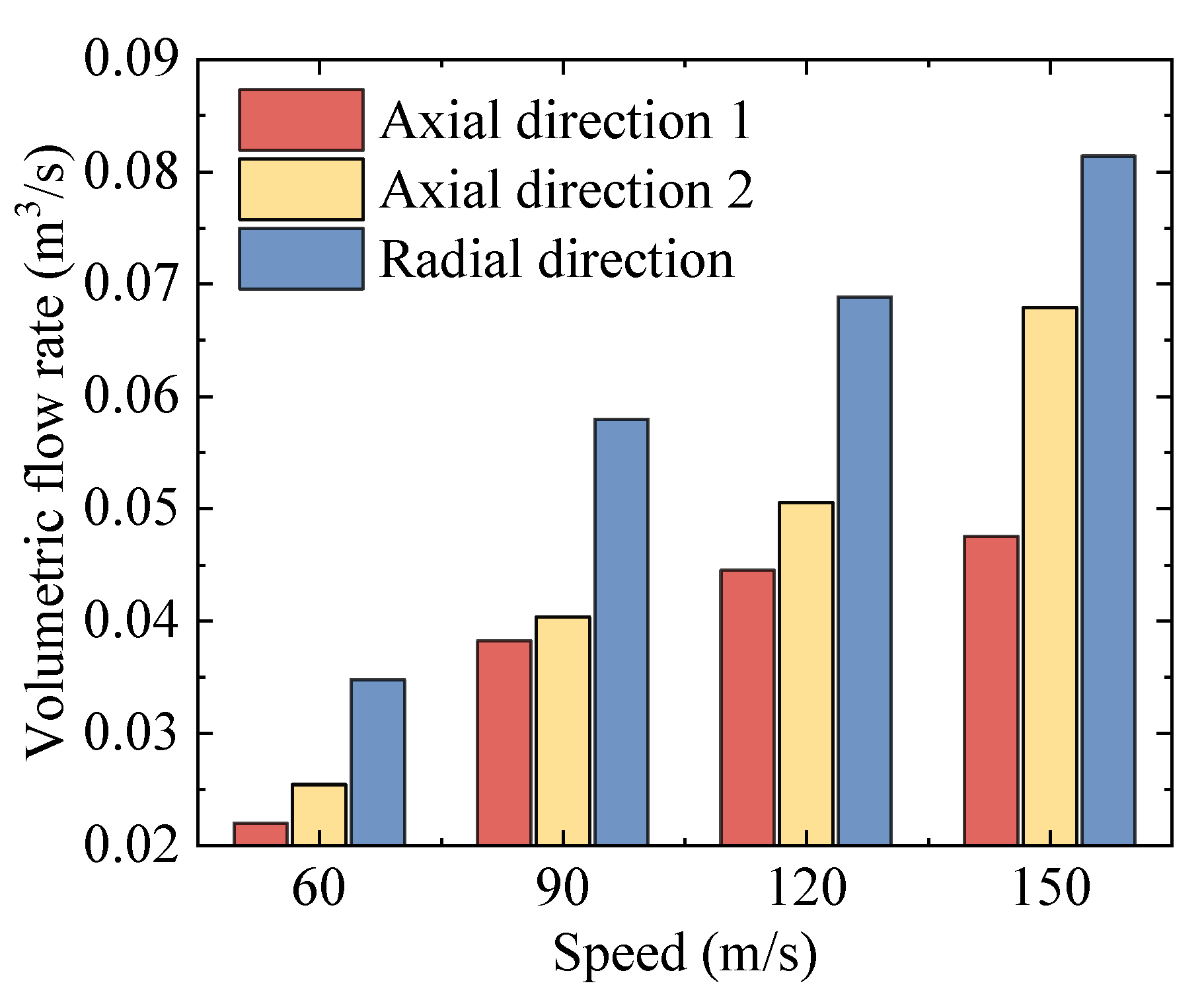
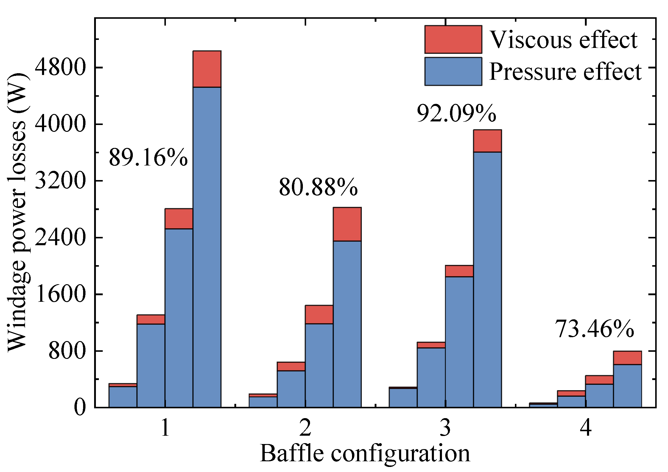
  • Pressure loss accounts for the main part of WPL, which has a positive correlation with the volumetric flow rate between teeth.
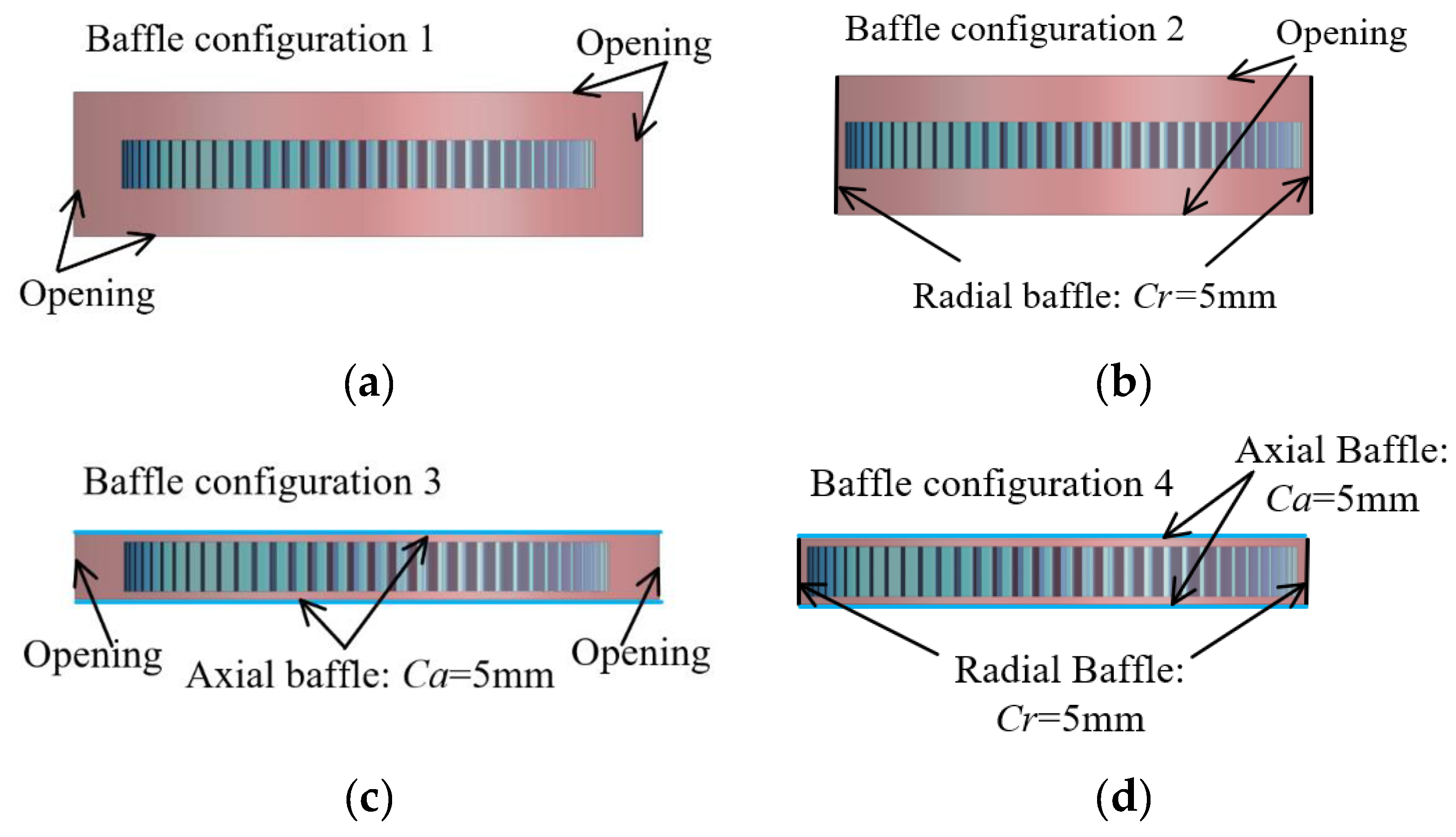
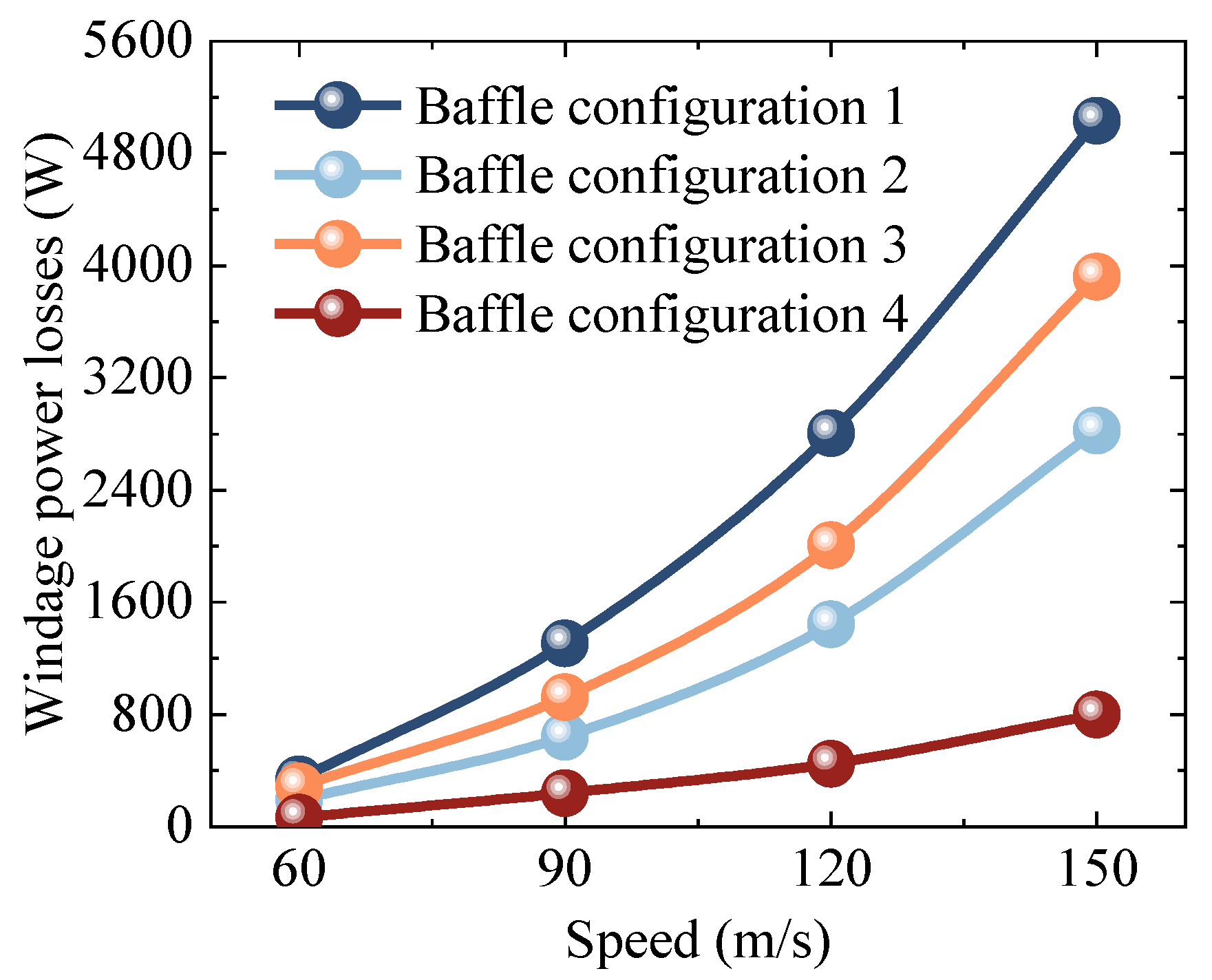
  • The radial baffle mainly reduces the pressure loss, while the power loss caused by the viscous effect is mainly affected by the axial baffle. The radial baffles perform better than axial baffles, and smaller clearance achieves a better result in reducing WPL. The combination configuration of the radial baffle and axial baffle reduces WPL to 16% compared with the non-baffle configuration.
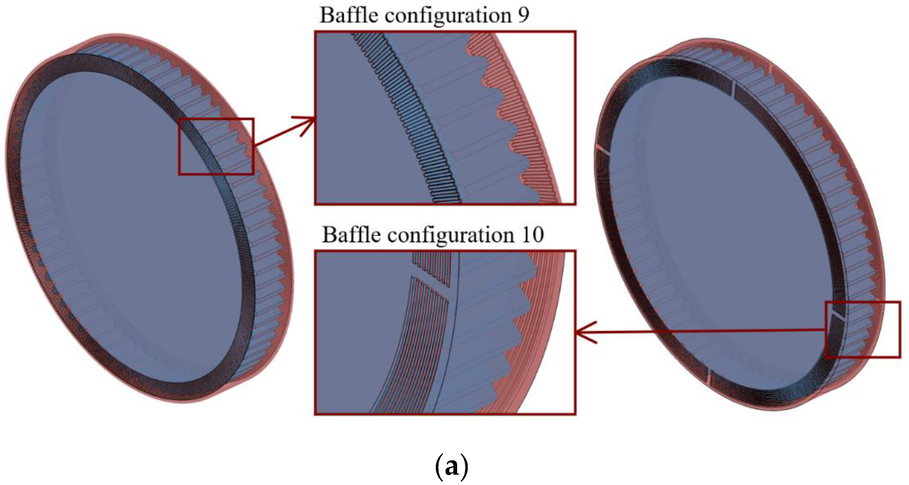
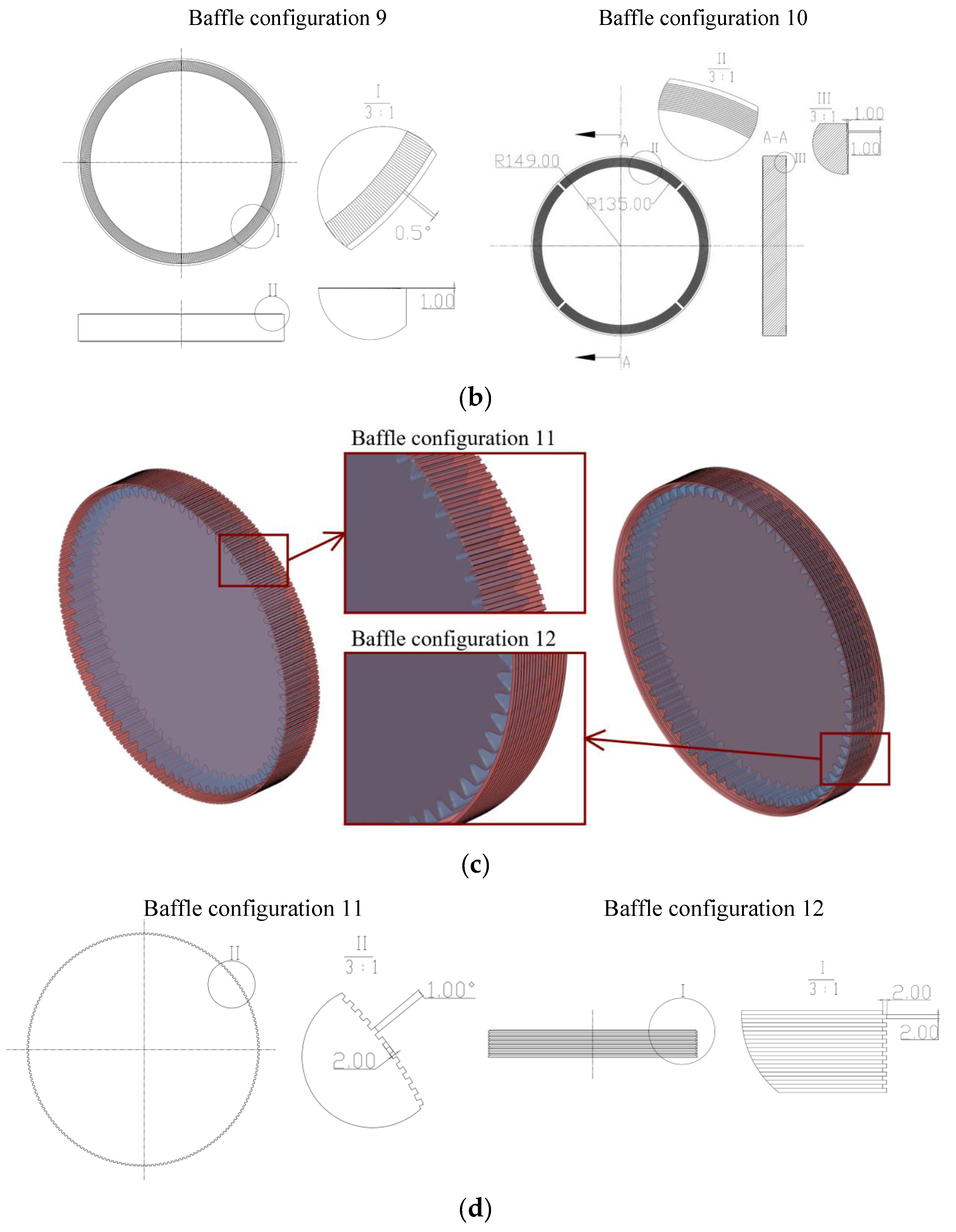
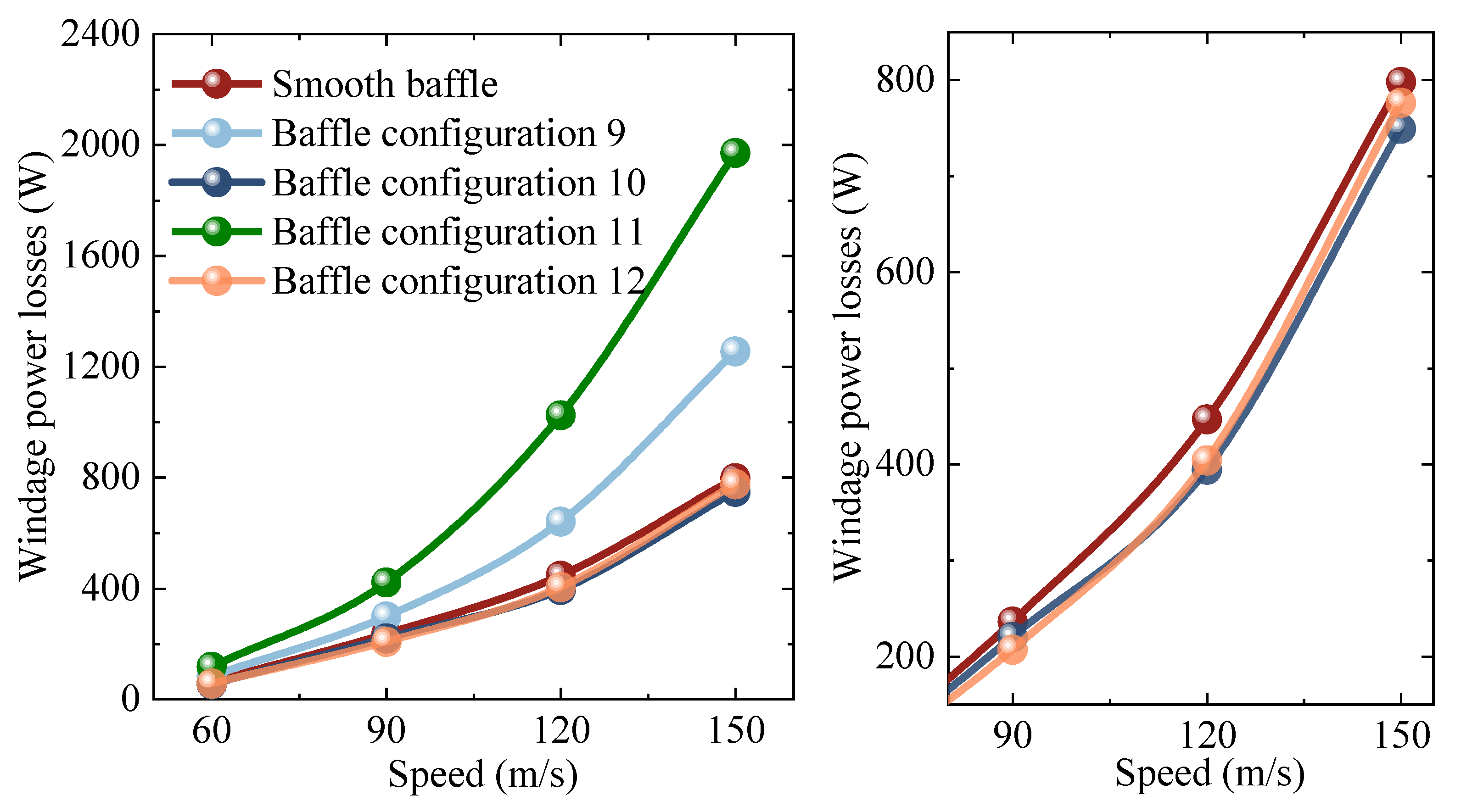
  • The baffles with circular grooves can further promote the reduction of WPL by 8.2% compared with smooth baffles, while the straight grooves will weaken the effect of the baffle.
Based on the study on the windage effect of a high-speed gear and the influence of a baffle, in this paper, further efforts are underway to explore the windage characteristics and power loss in the oil-gas two-phase flow field.

Author Contributions

Conceptualization, Y.Z. and X.H.; methodology, Y.Z. and H.Z.; formal analysis, Y.Z. and H.Z.; investigation, J.Z.; data curation, Y.Z. and J.Z.; writing—original draft preparation, Y.Z.; supervision, H.Z. and X.H.; funding acquisition, X.H. and H.Z. All authors have read and agreed to the published version of the manuscript.

Funding

This research was funded by the National Key Research and Development Program of China (Grant No. 2020YFB2008100), the National Natural Science Foundation of China (Grant No. 52105060) and the Postgraduate Research and Practice Innovation Program of NUAA (Grant No. xcxjh20210515).

Institutional Review Board Statement

Not applicable.

Informed Consent Statement

Not applicable.

Data Availability Statement

All the data are shown in the tables and figures of this paper.

Acknowledgments

The author gratefully acknowledges the financial support of the National Key Research and Development Program of China (Grant No. 2020YFB2008100), the National Natural Science Foundation of China (Grant No. 52105060) and the Postgraduate Research and Practice Innovation Program of NUAA (Grant No. xcxjh20210515).

Conflicts of Interest

The authors declare no conflict of interest.

References

  1. Petry-Johnson, T.T.; Kahraman, A.; Anderson, N.E.; Chase, D.R. An experimental investigation of spur gear efficiency. J. Mech. Des. 2008, 130, 062601. [Google Scholar] [CrossRef] [Green Version]
  2. Ambarisha, V.K.; Parker, R.G. Nonlinear dynamics of planetary gears using analytical and finite element models. J. Sound Vib. 2007, 302, 557–595. [Google Scholar] [CrossRef]
  3. Fernandes, C.M.C.G.; Marques, C.M.P.; Martins, R.C.; Seabra, J.H.O. Gearbox power loss. Part III: Application to a parallel axis and a planetary gearbox. Tribol. Int. 2015, 88, 317–326. [Google Scholar] [CrossRef]
  4. Kahnamouei, J.T.; Yang, J. Development and verification of a computationally efficient stochastically linearized planetary gear train model with ring elasticity. Mech. Mach. Theory 2021, 155, 104061. [Google Scholar] [CrossRef]
  5. Marchesse, Y.; Ruzek, M.; Ville, F.; Velex, P. On windage power loss reduction achieved by flanges. Forschung im Ingenieurwesen 2021, 85, 1–6. [Google Scholar] [CrossRef]
  6. Massini, D.; Fondelli, T.; Andreini, A.; Facchini, B.; Tarchi, L.; Leonardi, F. Experimental and numerical investigation on windage power losses in high speed gears. J. Eng. Gas Turb. Power 2018, 140, 082508. [Google Scholar] [CrossRef]
  7. Winfree, D.D. Reducing gear windage losses from high speed gears and applying these principles to actual running hardware. In Proceedings of the ASME International Design Engineering Technical Conferences & Computers & Information in Engineering Conference, Portland, OR, USA, 4–7 August 2013. [Google Scholar]
  8. Ruzek, M.; Marchesse, Y.; Ville, F.; Velex, P. Windage power loss reductions in high-speed gear pairs. Forschung im Ingenieurwesen 2019, 83, 387–392. [Google Scholar] [CrossRef]
  9. Ruzek, M.; Ville, F.; Velex, P.; Boni, J.B.; Marchesse, Y. On windage losses in high-speed pinion-gear pairs. Mech. Mach. Theory 2019, 132, 123–132. [Google Scholar] [CrossRef]
  10. Delgado, I.R.; Hurrell, M.J. Baseline experimental results on the effect of oil temperature on shrouded meshed spur gear windage power loss. In Proceedings of the ASME 2017 International Design Engineering Technical Conferences and Computers and Information in Engineering Conference, Cleveland, OH, USA, 6–9 August 2017. [Google Scholar]
  11. Delgado, I.; Hurrell, M. Experimental investigation of shrouding on meshed spur gear windage power loss. In Proceedings of the American Helicopter Society’s 73rd Annual Forum, Fort Worth, TX, USA, 9–11 May 2017. [Google Scholar]
  12. Zhu, X.; Dai, Y.; Ma, F. Development of a quasi-analytical model to predict the windage power losses of a spiral bevel gear. Tribol. Int. 2020, 146, 106258. [Google Scholar] [CrossRef]
  13. Pallas, S.; Marchesse, Y.; Changenet, C.; Ville, F.; Velex, P. A windage power loss model based on CFD study about the volumetric flow rate expelled by spur gears. Mech. Ind. 2012, 13, 317–323. [Google Scholar] [CrossRef]
  14. Dawson, P.H. Windage loss in larger high-speed gears. Proc. Inst. Mech. Eng. A-J. Pow. 1984, 198, 51–59. [Google Scholar] [CrossRef]
  15. Heingartner, P.; Mba, D. Determining power losses in helical gear mesh: Case study. In Proceedings of the ASME 2003 Design Engineering Technical Conferences and Computers and Information in Engineering Conference, Chicago, IL, USA, 2–6 September 2003. [Google Scholar]
  16. Anderson, N.E.; Loewenthal, S.H. Spur-Gear-System Efficiency at Part and Full Load. NASA Technical Paper No. 1622; 1980; Volume 79. Available online: https://ntrs.nasa.gov/citations/19800009206 (accessed on 15 April 2022).
  17. Al-Shibl, K.; Simmons, K.; Eastwick, C.N. Modelling windage power loss from an enclosed spur gear. Proc. Inst. Mech. Eng. A-J. Pow. 2007, 221, 331–341. [Google Scholar] [CrossRef] [Green Version]
  18. Hill, M.J.; Kunz, R.F.; Noack, R.W.; Long, L.N.; Morris, P.J.; Handschuh, R.F. Application and validation of unstructured overset CFD technology for rotorcraft gearbox windage aerodynamics simulation. In Proceedings of the 64th Annual Forum of the American Helicopter Society, Montreal, QC, Canada, 29 April–1 May 2008. [Google Scholar]
  19. Concli, F.; Gorla, C.; Torre, A.D.; Montenegro, G. Windage power losses of ordinary gears: Different CFD approaches aimed to the reduction of the computational effort. Lubricants 2014, 2, 162–176. [Google Scholar] [CrossRef]
  20. Zhu, X.; Dai, Y.; Ma, F. On the estimation of the windage power losses of spiral bevel gears: An analytical model and CFD investigation. Simul. Model. Pract. Theory 2021, 110, 102334. [Google Scholar] [CrossRef]
  21. Dai, Y.; Xu, L.; Zhu, X.; Ouyang, B. Application of an unstructured overset method for predicting the gear windage power losses. Eng. Appl. Comp. Fluid 2021, 15, 130–141. [Google Scholar] [CrossRef]
  22. Fondelli, T.; Andreini, A.; Facchini, B. Numerical investigation on windage losses of high-speed gears in enclosed configuration. AIAA J. 2018, 56, 1910–1921. [Google Scholar] [CrossRef]
  23. Hill, M.J.; Kunz, R.F.; Medvitz, R.B.; Handschuh, R.F.; Long, L.N.; Noack, R.W.; Morris, P.J. CFD analysis of gear windage losses: Validation and parametric aerodynamic studies. J. Fluid Eng.-T. ASME 2011, 133, 031103. [Google Scholar] [CrossRef] [Green Version]
  24. He, A.; Deng, R.; Xiong, Y. CFD study on the windage power loss of high speed gear. IOP Conf. Ser.: Mater. Sci. Eng 2019, 473, 012044. [Google Scholar] [CrossRef]
  25. Li, S.; Li, L. Computational investigation of baffle influence on windage loss in helical geared transmissions. Tribol. Int. 2021, 156, 106852. [Google Scholar] [CrossRef]
  26. Dai, Y.; Ma, F.; Zhu, X.; Jia, J. Numerical simulation investigation on the windage power loss of a high-speed face gear drive. Energies 2019, 12, 2093. [Google Scholar] [CrossRef] [Green Version]
  27. Zhu, X.; Dai, Y.; Ma, F. CFD modelling and numerical simulation on windage power loss of aeronautic high-speed spiral bevel gears. Simul. Model. Pract. Theory 2020, 103, 102080. [Google Scholar] [CrossRef]
  28. Zhang, Y.; Li, L.; Zhao, Z. Optimal design of computational fluid dynamics: Numerical calculation and simulation analysis of windage power losses in the aviation. Processes 2021, 9, 1999. [Google Scholar] [CrossRef]
Figure 1. Computational domain and baffle settings: (a) Computational domain; (b) Axial baffle; (c) Radial baffle.
Machines 10 00416 g001
Figure 2. Axial clearance and radial clearance: (a) Three-dimensional model; (b) Engineering drawing.
Machines 10 00416 g002
Figure 3. Meshing of computational domain.
Machines 10 00416 g003
Figure 4. Fluid domain of a gear pair.
Machines 10 00416 g004
Figure 5. WPL: (a) Comparison of numerical results and theoretical results obtained by the formula of Dawson; (b) Proportion of the pressure and the viscous effect.
Machines 10 00416 g005
Figure 6. Pressure surface and suction surface: (a) Simulation of a single gear; (b) Simulation of a gear pair.
Machines 10 00416 g006
Figure 7. Streamline in the axial cross-section: (a) Simulation of a single gear; (b) Simulation of a gear pair.
Machines 10 00416 g007
Figure 8. Volumetric flow rate drawn or expelled between the teeth in the simulation of a single gear.
Machines 10 00416 g008
Figure 9. Four baffle configurations: (a) Baffle configuration 1: non-baffle; (b) Baffle configuration 2: radial baffle only; (c) Baffle configuration 3: axial baffle only; (d) Baffle configuration 4: combined baffle comprising axial baffle and radial baffle.
Machines 10 00416 g009
Figure 10. WPL of different baffle configurations.
Machines 10 00416 g010
Figure 11. The streamline and velocity vector between the teeth: (a) Baffle configuration 1; (b) Baffle configuration 2; (c) Baffle configuration 3; (d) Baffle configuration 4.
Machines 10 00416 g011aMachines 10 00416 g011b
Figure 12. Proportion of the pressure and the viscous effect in different baffle configurations.
Machines 10 00416 g012
Figure 13. WPL of different baffle clearances.
Machines 10 00416 g013
Figure 14. Grooved baffle configurations: (a) Baffle configuration 9: straight grooves on the axial baffle and Baffle configuration 10: circular grooves on the axial baffle; (b) Engineering drawings of Baffle configuration 9 and 10; (c) Baffle configuration 11: straight grooves on the radial baffle and Baffle configuration 12: circular grooves on the radial baffle; (d) Engineering drawings of Baffle configuration 11 and 12.
Machines 10 00416 g014aMachines 10 00416 g014b
Figure 15. WPL of different grooved baffle configurations.
Machines 10 00416 g015
Table 1. Basic parameters of spur gear.
ParameterValue
Pitch diameter D (mm)288
Tooth width B (mm)30
Pressure angle α (°)20
Modulus m (mm)4
Table 2. Baffle configurations with different axial clearances and radial clearances.
Baffle ConfigurationCa (mm)Cr (mm)
455
5510
6515
7105
8155
Publisher’s Note: MDPI stays neutral with regard to jurisdictional claims in published maps and institutional affiliations.

