
Object Tracking for an Autonomous Unmanned Surface Vehicle


Abstract
:1. Introduction
2. Materials and Methods
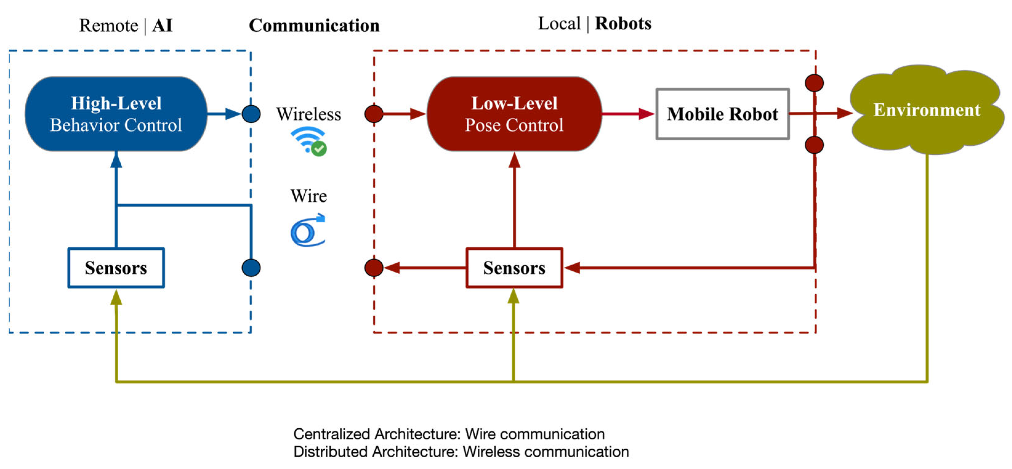
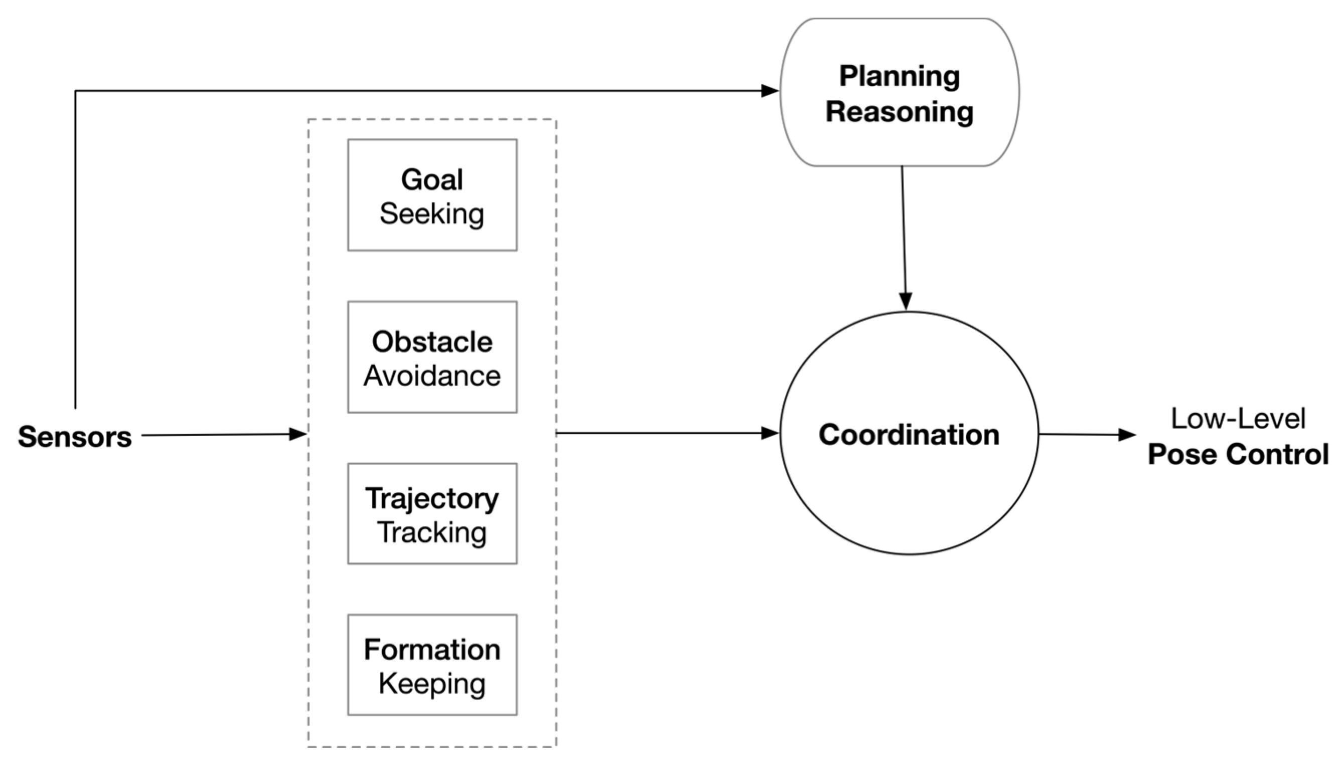
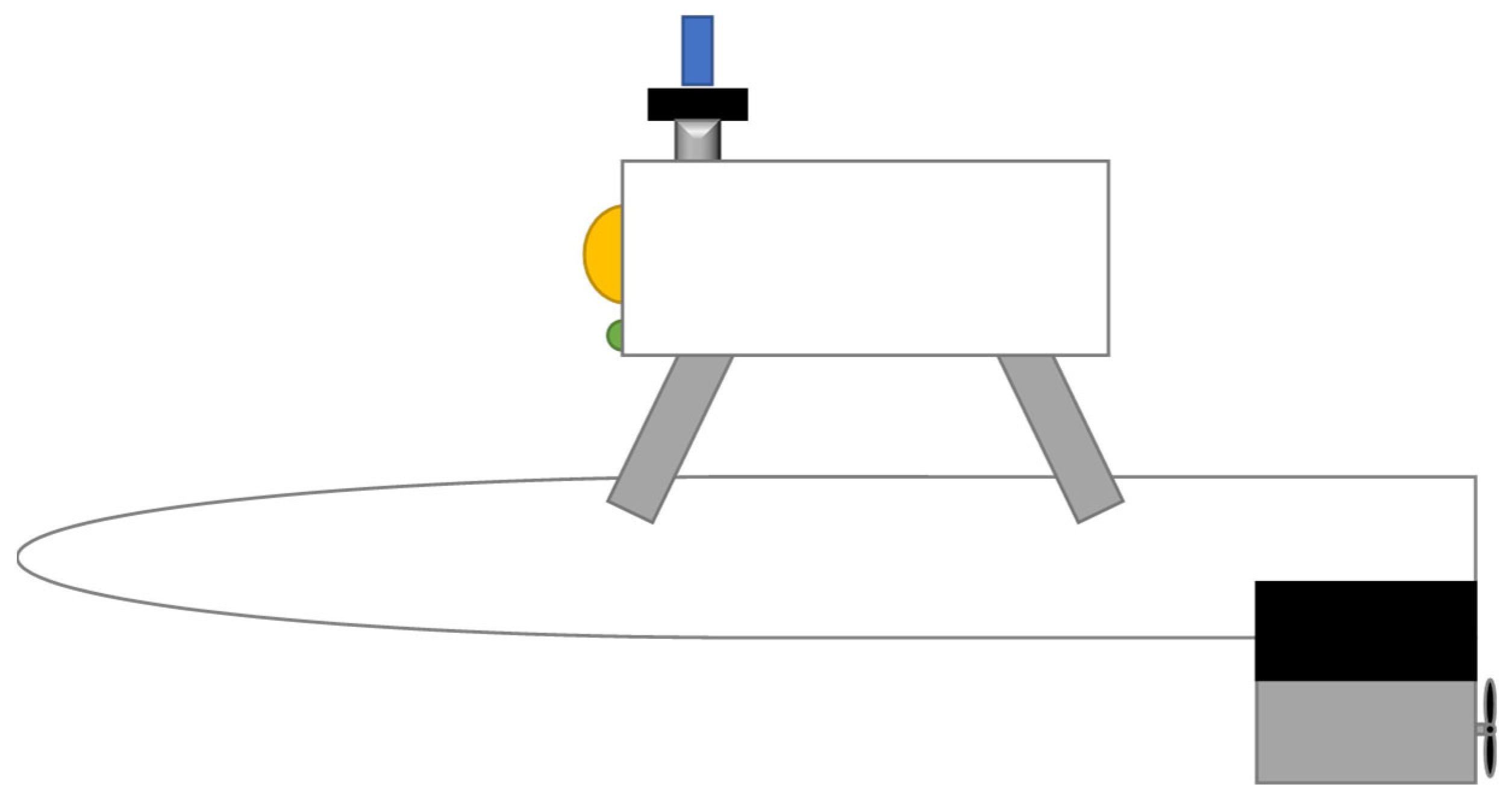
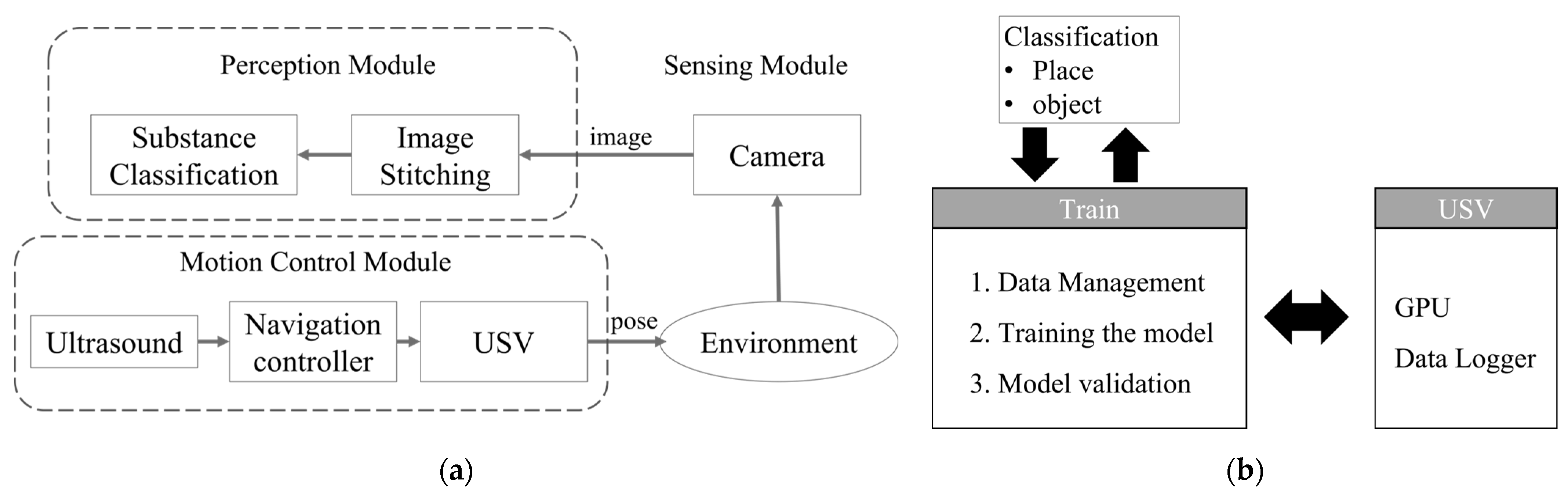
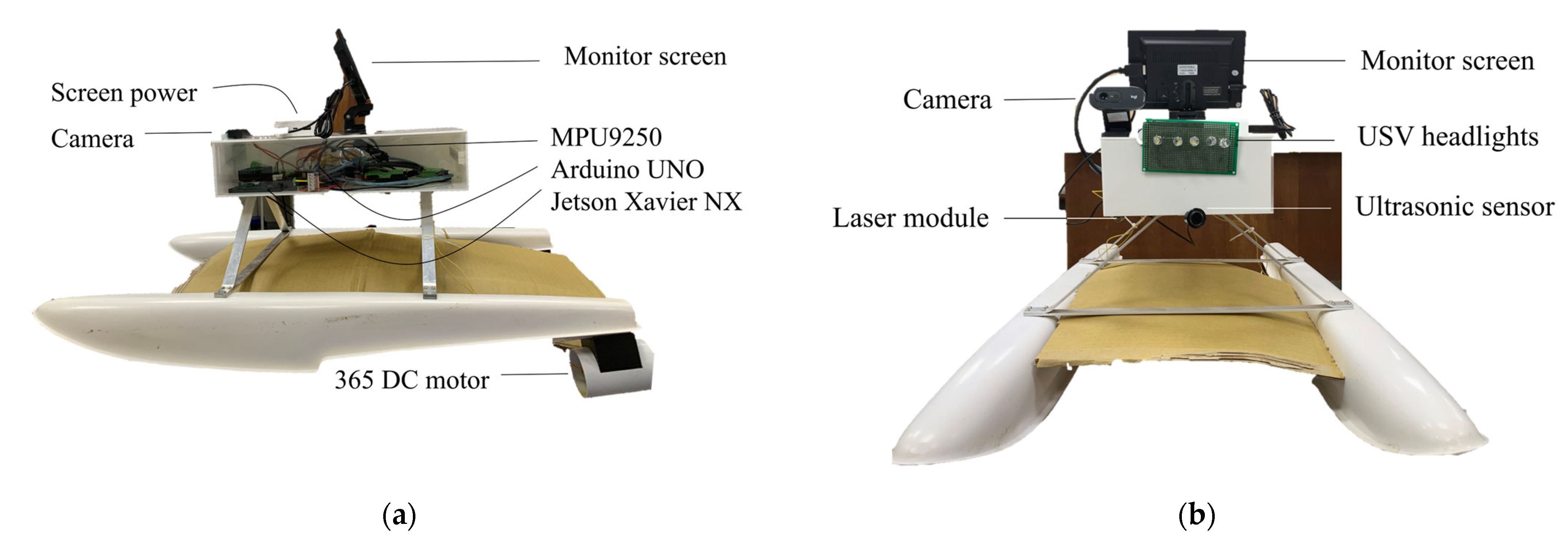
2.1. Robot System
2.2. Algorithm
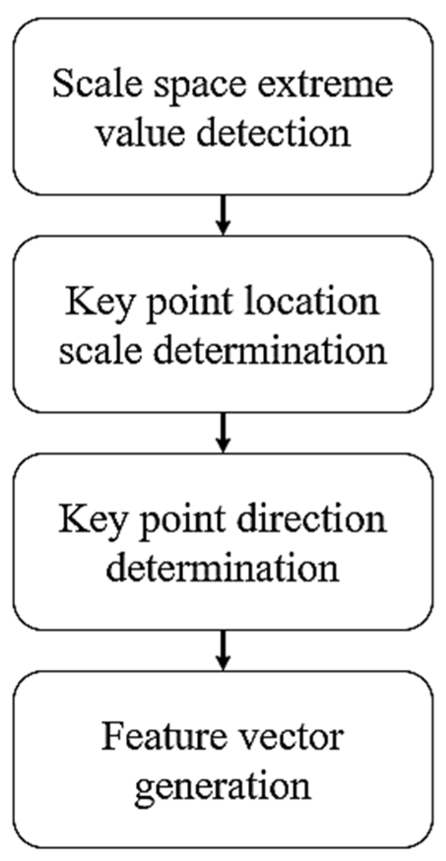
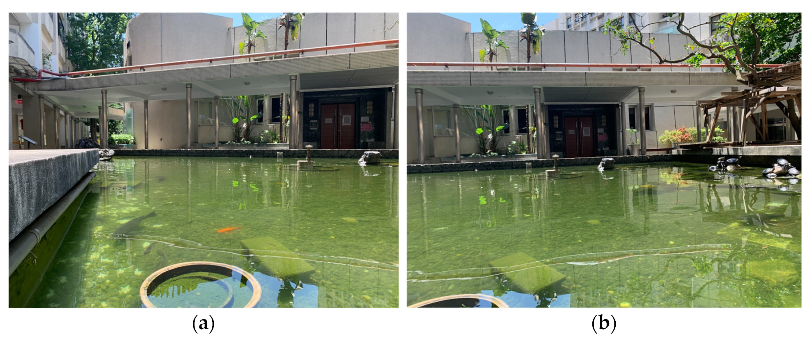
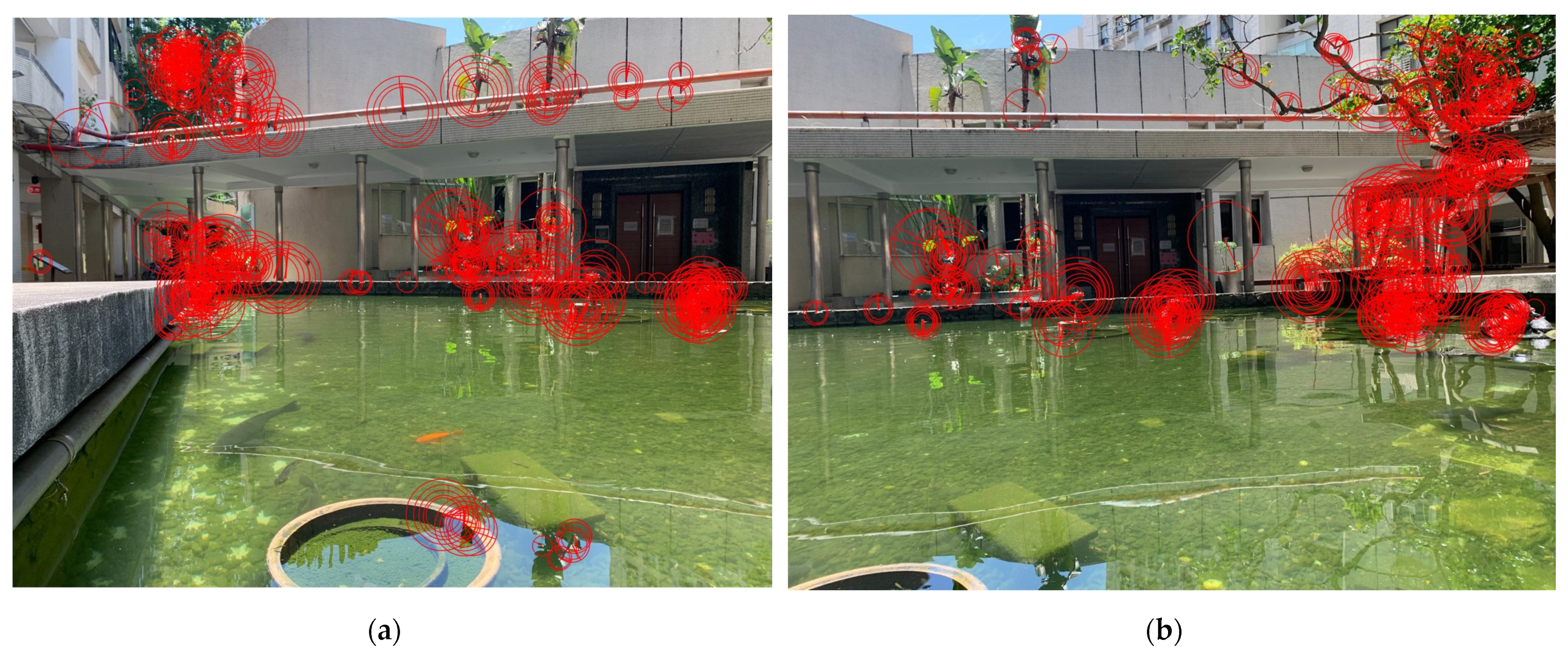
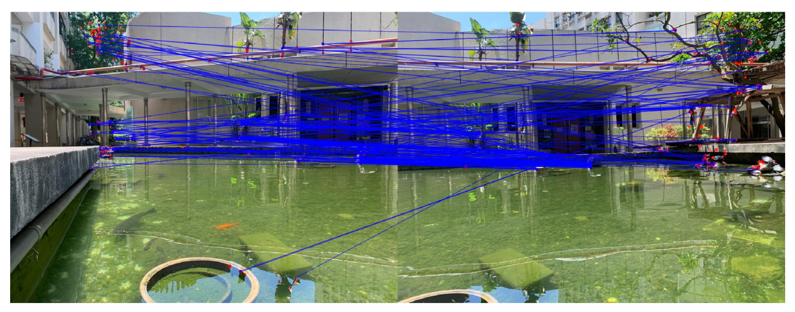
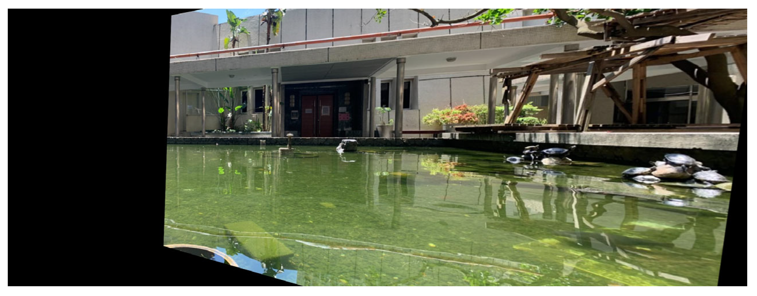
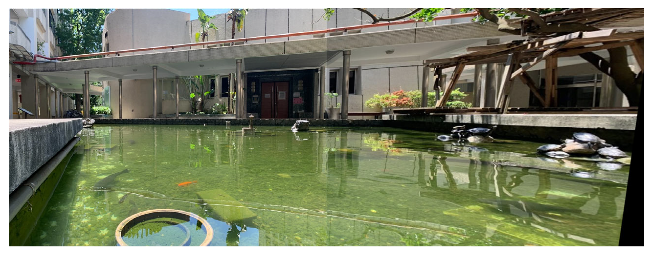
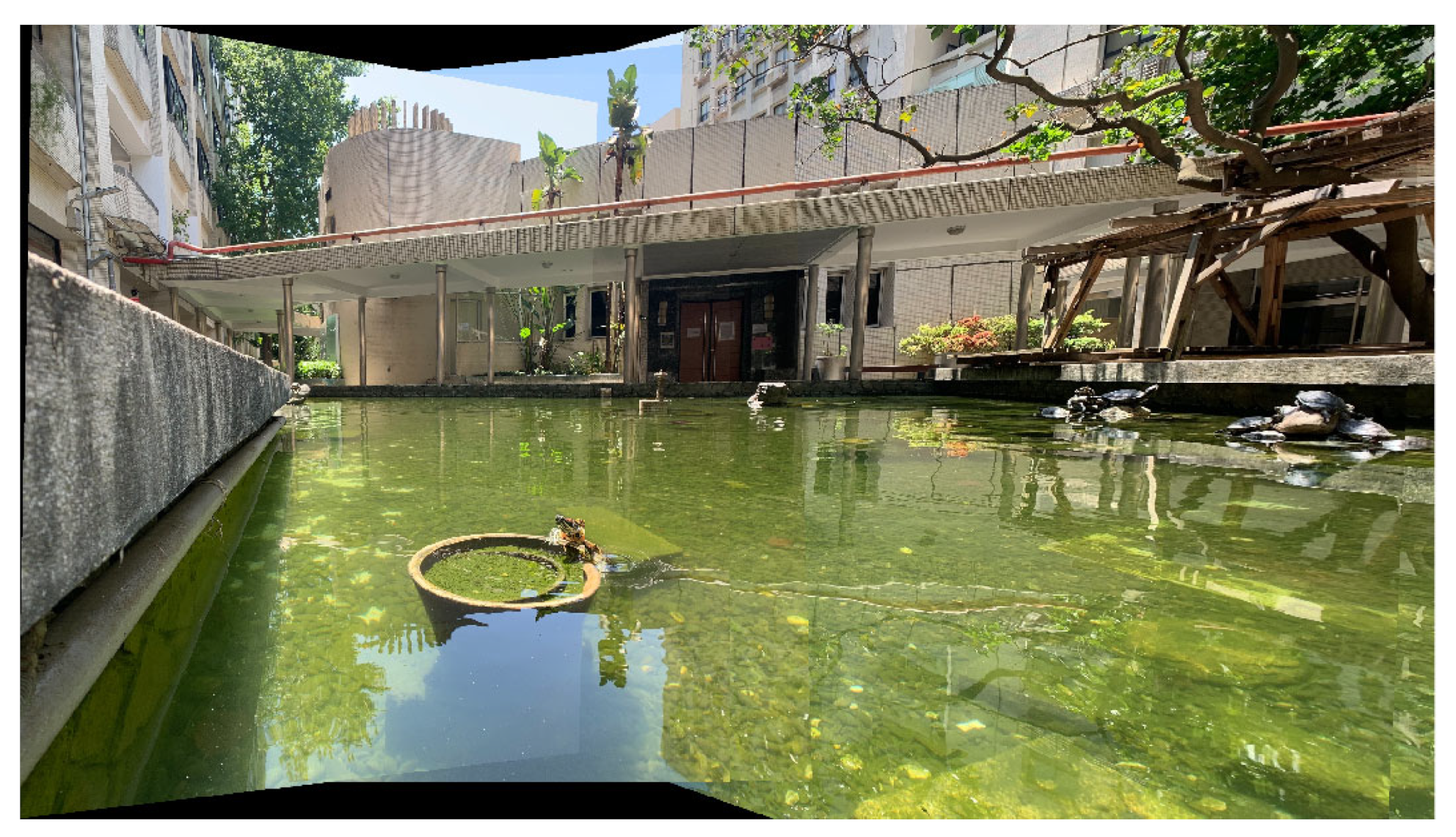
2.2.1. Feature-Based Panoramic Image Stitching
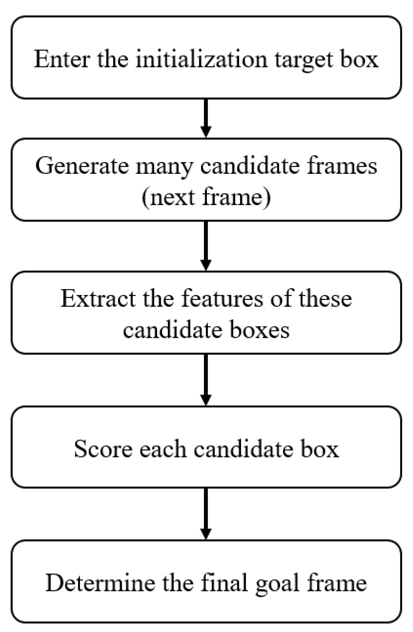
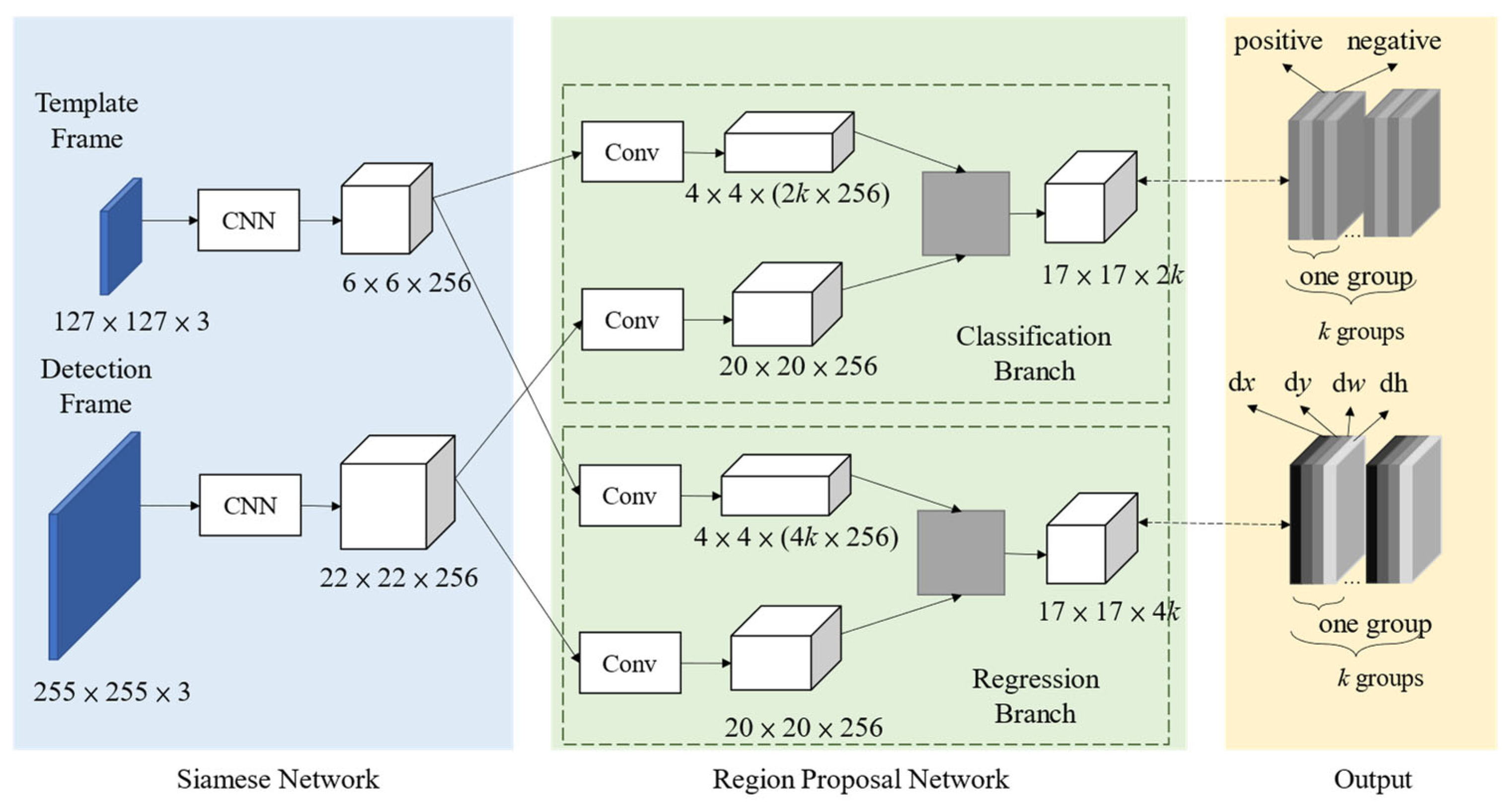
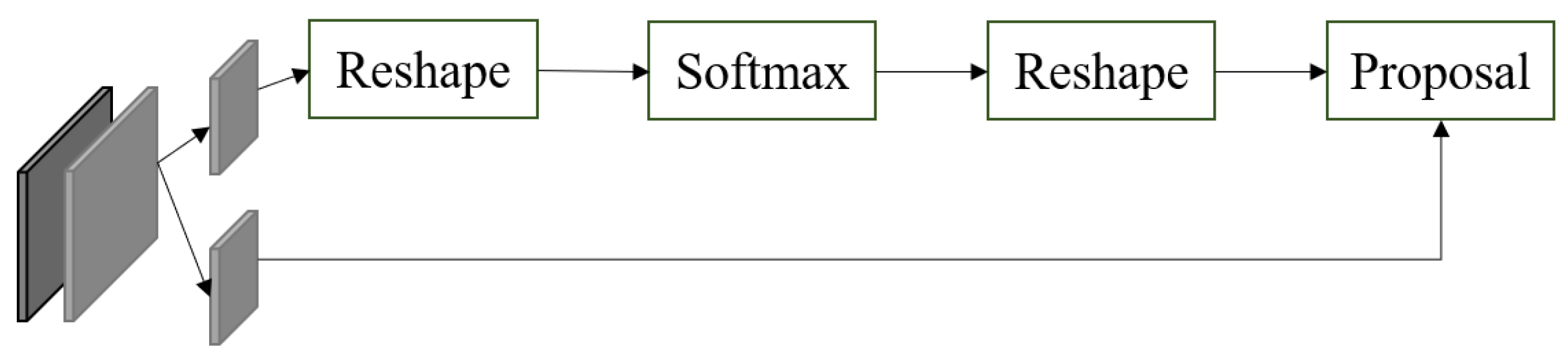
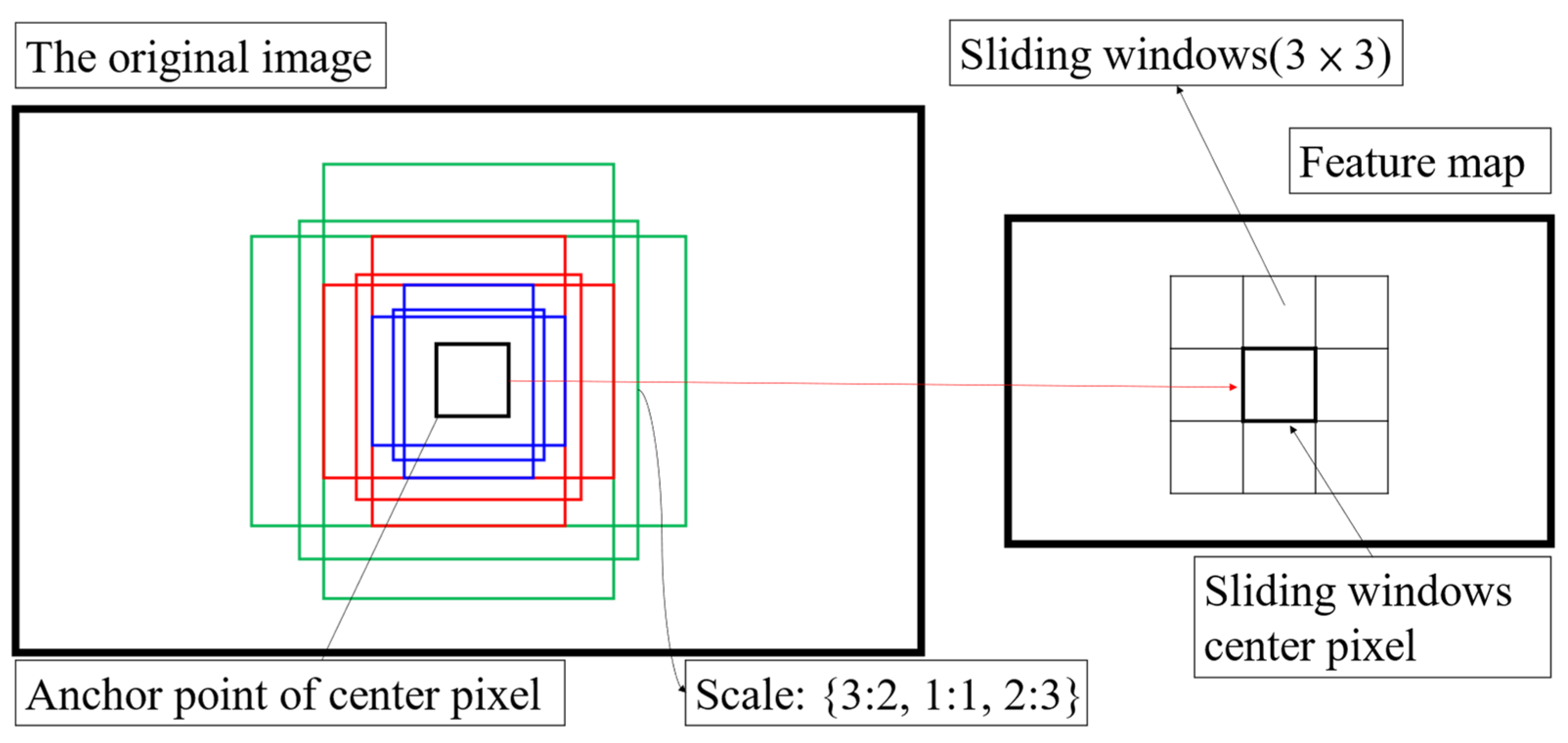
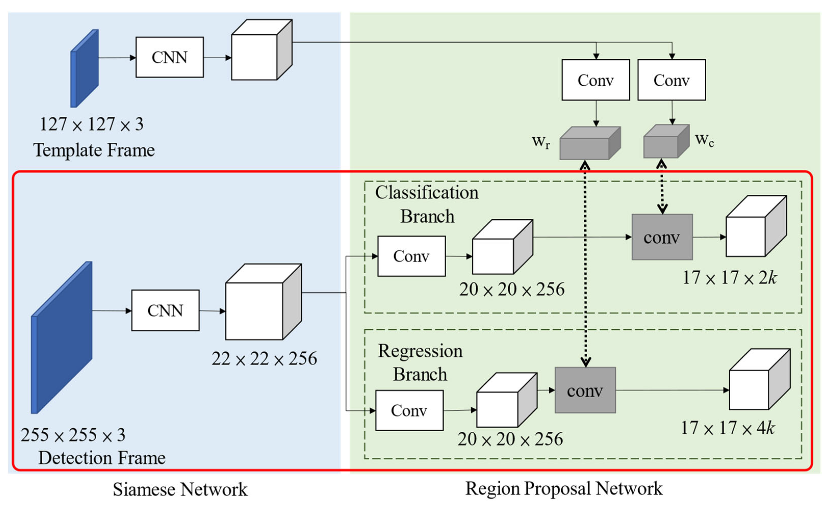
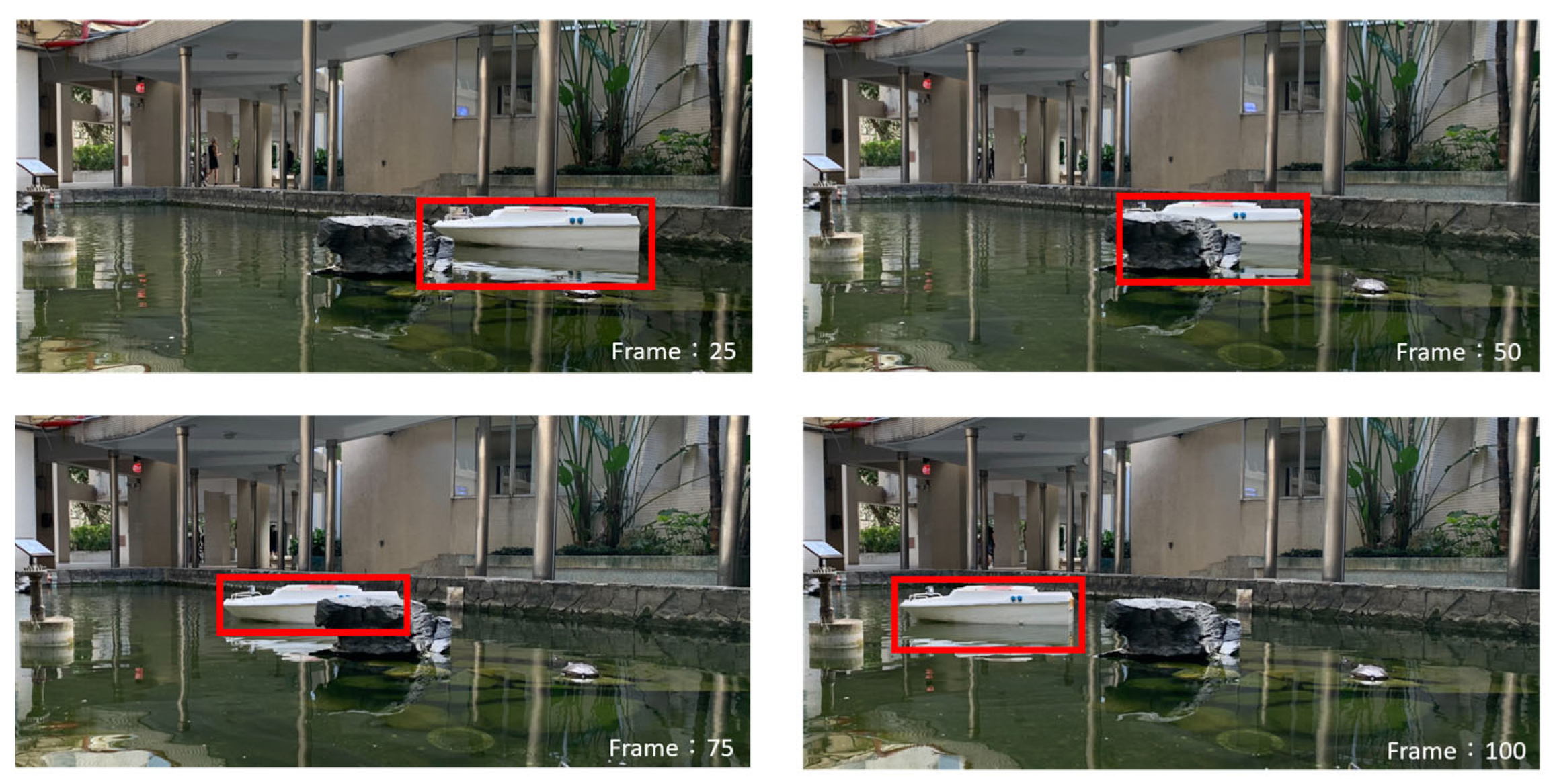
2.2.2. Siamese-Based Target Tracking
| Algorithm 1 Keyframe detection | |
| Inputs: | f, the frame of the input video stream; MAMf, the motion appearance mask of f; MAMf–1, the motion appearance mask of f − 1; tstop, the temporal threshold for detecting stop; |MAMf∣ denotes the total number of ls in MAMf; |
| Outputs: | lf, the label of the keyframe; |
| 1. | if |MAMf∣ > |MAMf−1∣ |
| 2. | lf = SPLIT |
| 3. | else if |MAMf∣ < |MAMf−1∣ |
| 4. | lf = JOIN |
| 5. | else if MAMf ^ MAMf−1 ≠ 0 |
| 6. | lf = MOVE |
| 7. | else /*MAMf = MAMf−1 */ |
| 8. | stop-count ← stop-count + 1 |
| 9. | if stop-count > tstop |
| 10. | lf = SPLIT |

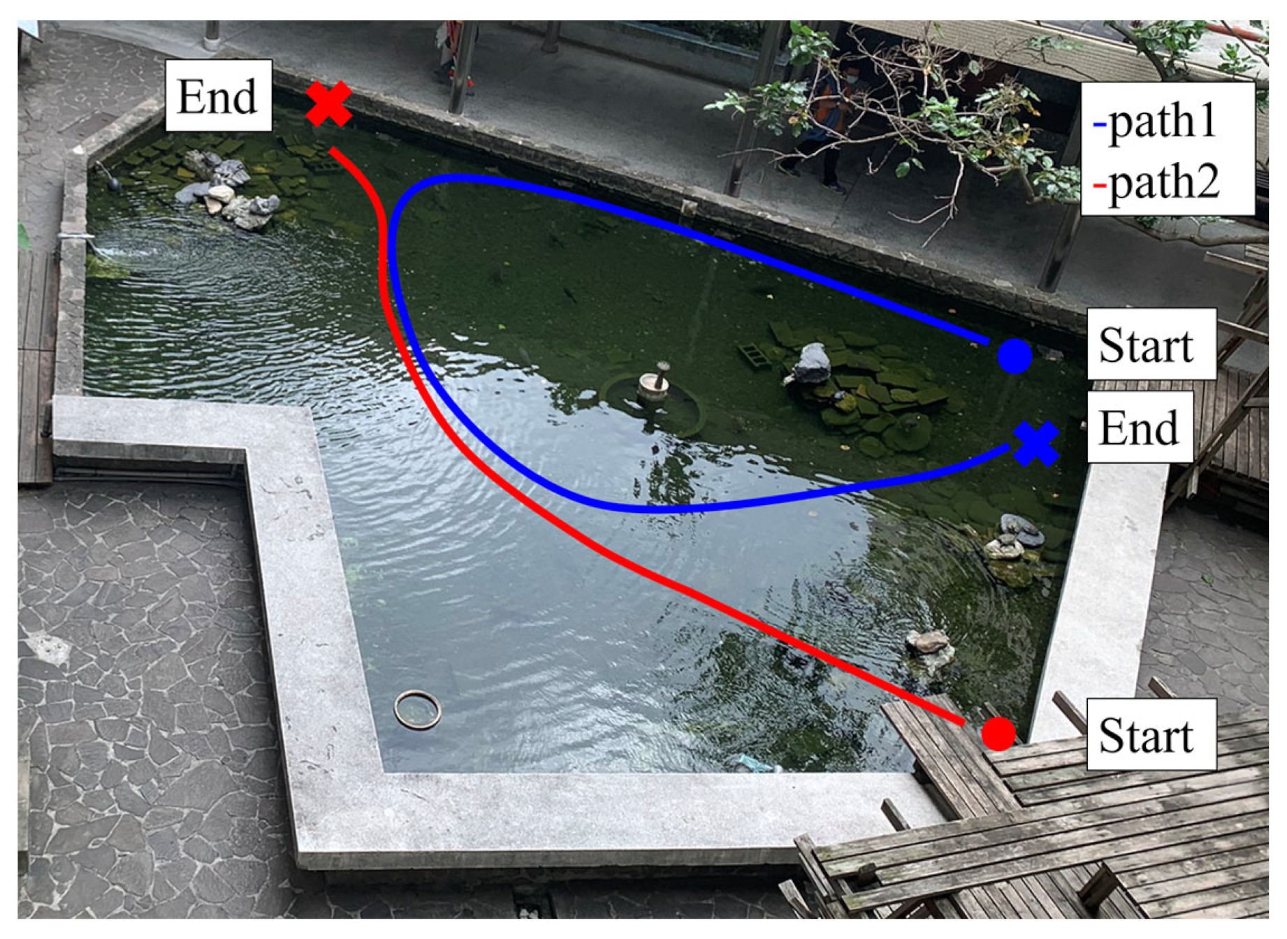
3. Results

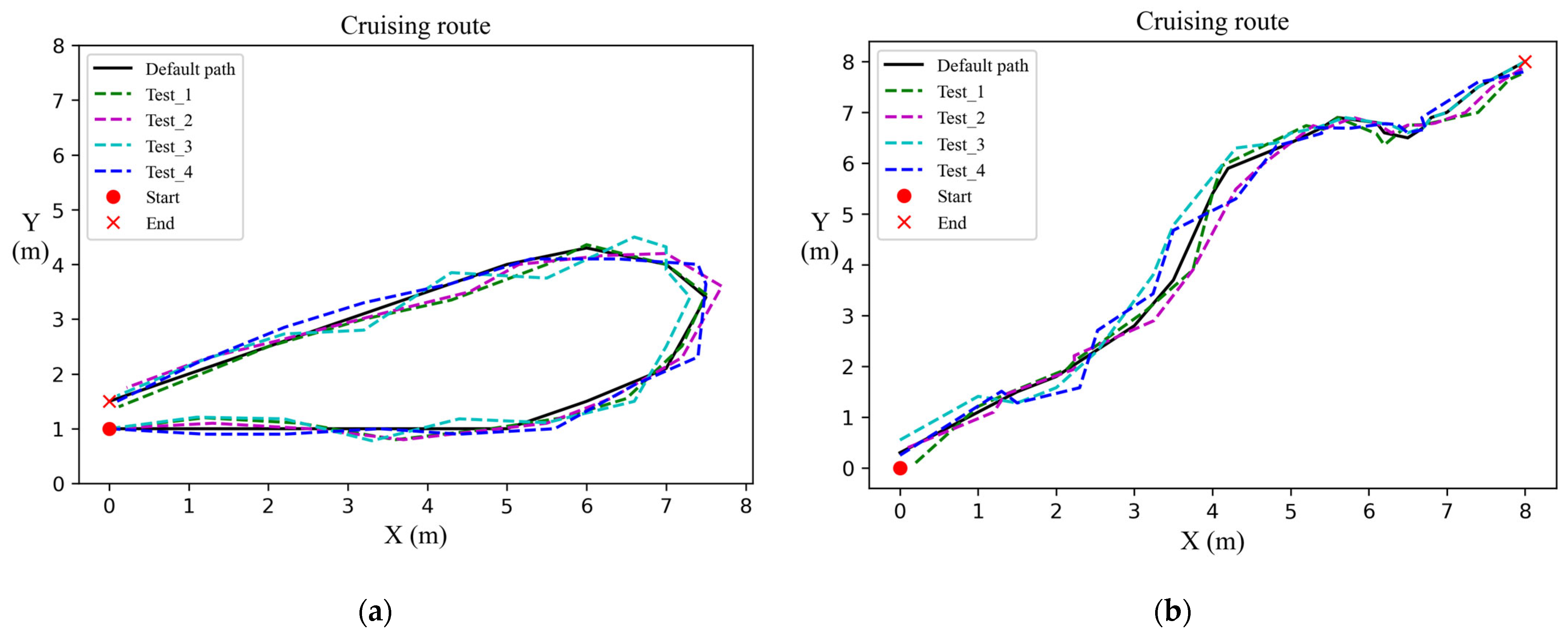
| Trajectory | Path1 | Path2 |
|---|---|---|
| Metric | ATE | |
| Test_1 | 3.745 | 4.045 |
| Test_2 | 3.749 | 3.704 |
| Test_3 | 7.341 | 19.363 |
| Test_4 | 6.958 | 4.499 |
| Avg. Err. | 5.473 | 7.903 |


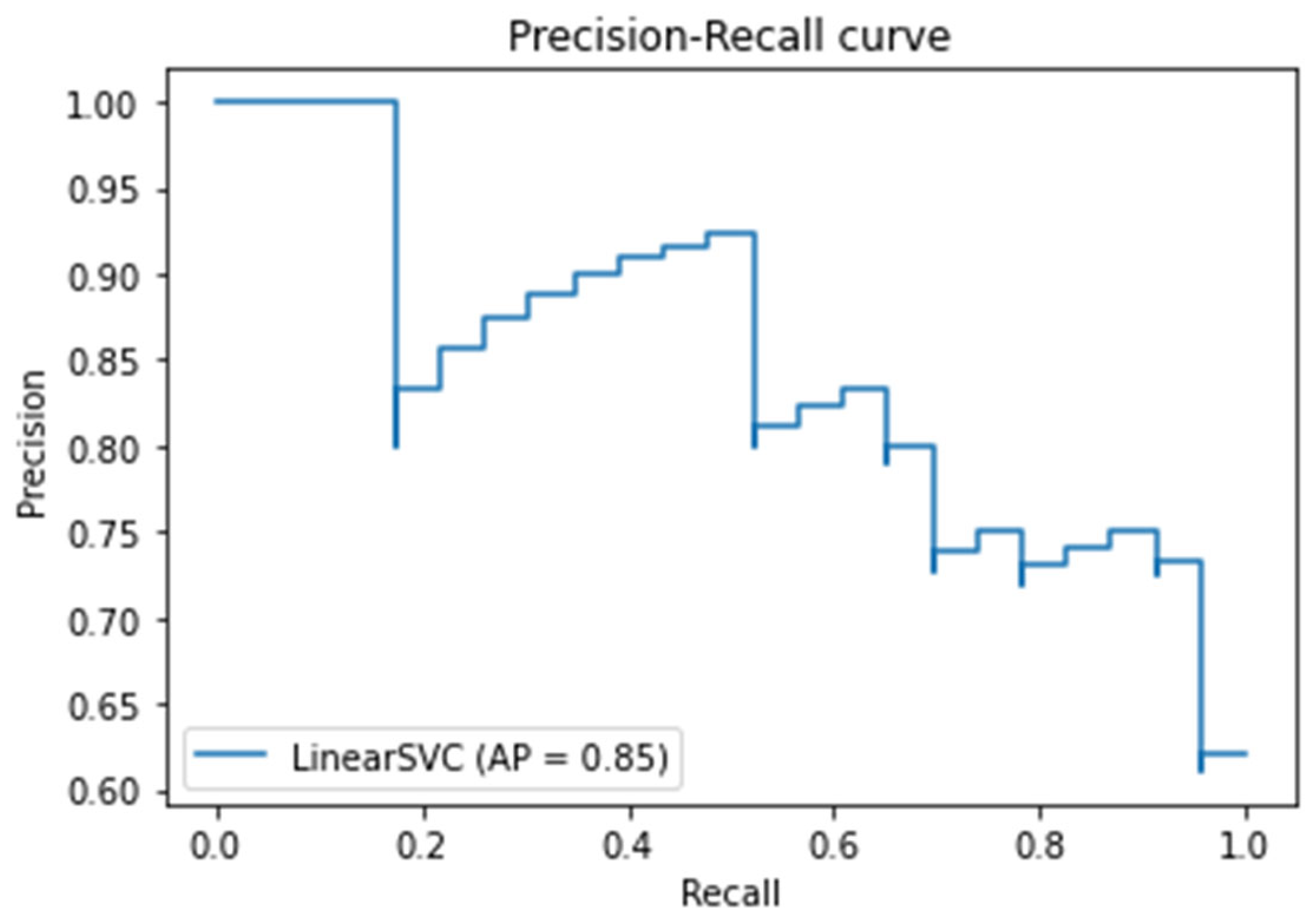
| Data Set | Precision | Recall | F1 Scores |
|---|---|---|---|
| Daytime | 0.85 | 0.61 | 0.711 |
| Night | 0.74 | 0.82 | 0.778 |


| Day-Time Data Set | Predicted | ||
|---|---|---|---|
| Positive | Negative | ||
| Actual | Positive | 1250 | 782 |
| Negative | 221 | 575 | |
| Night-Time Data Set | Predicted | ||
|---|---|---|---|
| Positive | Negative | ||
| Actual | Positive | 751 | 166 |
| Negative | 263 | 323 | |

4. Discussion
5. Conclusions
Author Contributions
Funding
Institutional Review Board Statement
Informed Consent Statement
Data Availability Statement
Conflicts of Interest
References
- Suzuki, N.; Kitajima, H.; Kaba, H.; Suzuki, T.; Suto, T.; Kobayashi, A.; Ochi, F. An Experiment of Real-Time Data Transmission of Sonar Images from Cruising UUV to Distant Support Vessel via USV: Development of Underwater Real-Time Communication System (URCS) by Parallel Cruising. In Proceedings of the OCEANS 2015—Genova, Genova, Italy, 18–21 May 2015; pp. 1–6. [Google Scholar]
- Simetti, E.; Turetta, A.; Casalino, G.; Cresta, M. Towards the Use of a Team of USVs for Civilian Harbour Protection: The Problem of Intercepting Detected Menaces. In Proceedings of the OCEANS’10 IEEE SYDNEY, Sydney, NSW, Australia, 24–28 May 2010; pp. 1–7. [Google Scholar]
- Kent, B.M.; Ehret, R.A. Rethinking Intelligence, Surveillance, and Reconnaissance in a Wireless Connected World. In Proceedings of the IEEE International Symposium on Antennas and Propagation, Chicago, IL, USA, 8–14 July 2012; pp. 1–2. [Google Scholar]
- Duan, L.; Luo, B.; Li, Q.-Y.; Yu, G.-H. Research on intelligence, surveillance and reconnaissance mission planning model and method for naval fleet. In Proceedings of the Chinese Control and Decision Conference, Yinchuan, China, 28–30 May 2016; pp. 2419–2424. [Google Scholar]
- Alshbatat, A.I.N.; Alhameli, S.; Almazrouei, S.; Alhameli, S.; Almarar, W. Automated Vision-based Surveillance System to Detect Drowning Incidents in Swimming Pools. In Proceedings of the Advances in Science and Engineering Technology International Conferences, Dubai, United Arab Emirates, 4 February–9 April 2020; pp. 1–5. [Google Scholar]
- Uz, S.S.; Ames, T.J.; Memarsadeghi, N.; McDonnell, S.M.; Blough, N.V.; Mehta, A.V.; McKay, J.R. Supporting Aquaculture in the Chesapeake Bay Using Artificial Intelligence to Detect Poor Water Quality with Remote Sensing. In Proceedings of the IEEE International Geoscience and Remote Sensing Symposium, Waikoloa, HI, USA, 26 September–2 October 2020; pp. 3629–3632. [Google Scholar]
- Lambrou, T.P.; Anastasiou, C.C.; Panayiotou, C.; Polycarpou, M.M. A Low-Cost Sensor Network for Real-Time Monitoring and Contamination Detection in Drinking Water Distribution Systems. IEEE Sens. J. 2014, 14, 2765–2772. [Google Scholar] [CrossRef]
- Yunsheng, F.; Yutong, S.; Guofeng, W. On Model Parameter Identification and Trajectory Tracking Control for USV Based on Backstepping. In Proceedings of the 36th Chinese Control Conference, Dalian, China, 26–28 July 2017; pp. 4757–4761. [Google Scholar]
- Wang, P.; Wang, J. A Tracking Method Based on Target Classification and Recognition. In Proceedings of the IEEE Advanced Information Technology, Electronic and Automation Control Conference, Chengdu, China, 20–22 December 2019; pp. 255–259. [Google Scholar]
- Xu, Y.; Xu, K.; Wan, J.; Xiong, Z.; Li, Y. Research on Particle Filter Tracking Method Based on Kalman Filter. In Proceedings of the IEEE Advanced Information Management, Communicates, Electronic and Automation Control Conference, Xi’an, China, 25–27 May 2018; pp. 1564–1568. [Google Scholar]
- Gundogdu, E.; Alatan, A.A. Method for learning deep features for correlation based visual tracking. In Proceedings of the Signal Processing and Communications Applications Conference, Antalya, Turkey, 9–11 June 2017; pp. 1–4. [Google Scholar]
- Ge, Y.; Zhong, L.; Qiang, Z.J. Research on Underactuated USV Path Following Algorithm. In Proceedings of the Information Technology, Networking, Electronic and Automation Control Conference, Chongqing, China, 12–14 June 2020; pp. 2141–2145. [Google Scholar]
- Ge, Y.; Zhong, L.; Qiang, Z.J. Research on USV Heading Control Method Based on Kalman Filter Sliding Mode Control. In Proceedings of the Cambridge Crystallographic Data Centre, Hefei, China, 29 April 2020; pp. 1547–1551. [Google Scholar]
- Han, J.; Cho, Y.; Kim, J. Coastal SLAM with Marine Radar for USV Operation in GPS-Restricted Situations. IEEE J. Ocean. Eng. 2019, 44, 300–309. [Google Scholar] [CrossRef]
- Zhou, X.; Wu, P.; Zhang, H.; Guo, W.; Liu, Y. Learn to Navigate: Cooperative Path Planning for Unmanned Surface Vehicles Using Deep Reinforcement Learning. IEEE Access 2019, 7, 165262–165278. [Google Scholar] [CrossRef]
- Mane, S.; Mangale, S. Moving Object Detection and Tracking Using Convolutional Neural Networks. In Proceedings of the International Confederation of Contamination Control Societies, Madurai, India, 21 September 2018; pp. 1809–1813. [Google Scholar]
- Inoue, Y.; Ono, T.; Inouer, K. Situation-Based Dynamic Frame-Rate Control for on-Line Object Tracking. In Proceedings of the International Japan-Africa Conference on Electronics, Communications and Computations, Alexandria, Egypt, 17–19 December 2018; pp. 119–122. [Google Scholar]
- Koskowich, B.J.; Rahnemoonfai, M.; Starek, M. Virtualot—A Framework Enabling Real-Time Coordinate Transformation & Occlusion Sensitive Tracking Using UAS Products, Deep Learning Object Detection & Traditional Object Tracking Techniques. In Proceedings of the IEEE International Symposium on Geoscience and Remote Sensing, Valencia, Spain, 23–27 July 2018; pp. 6416–6419. [Google Scholar]
- Liu, Y.; Meng, Z.; Zou, Y.; Cao, M. Visual Object Tracking and Servoing Control of a Nano-Scale Quadrotor: System, Algorithms, and Experiments. IEEE/CAA J. Autom. Sin. 2021, 8, 344–360. [Google Scholar] [CrossRef]
- Zhou, Y.; Wang, T.; Hu, R.; Su, H.; Liu, Y.; Liu, X.; Suo, J.; Snoussi, H. Multiple Kernelized Correlation Filters (MKCF) for Extended Object Tracking Using X-Band Marine Radar Data. IEEE Trans. Signal Process. 2019, 67, 3676–3688. [Google Scholar] [CrossRef]
- Varfolomieiev, A.; Lysenko, O. Modification of the KCF tracking method for implementation on embedded hardware platforms. In Proceedings of the International Conference Radio Electronics & Info Communications, Kiev, Ukraine, 11–16 September 2016; pp. 1–5. [Google Scholar]
- Kalal, Z.; Mikolajczyk, K.; Matas, J. Tracking-Learning-Detection. IEEE Trans. Pattern Anal. Mach. Intell. 2012, 34, 1409–1422. [Google Scholar] [CrossRef] [PubMed] [Green Version]
- Dattathreya; Han, S.; Kim, M.-J.; Maik, V.; Paik, J. Keypoint-based object tracking using modified median flow. In Proceedings of the IEEE International Conference on Consumer Electronics-Asia, Seoul, Korea, 26–28 October 2016; pp. 1–2. [Google Scholar]
- Jiu-Cai, J.; Jie, Z.; Feng, S. Modelling, manoeuvring analysis and course following for two unmanned surface vehicles driven by a single propeller and double propellers. In Proceedings of the 27th Chinese Control and Decision Conference, Qingdao, China, 23–25 May 2015; pp. 4932–4937. [Google Scholar]
- Sun, S.; Wang, N.; Liu, Y.; Dai, B. Fuzzy heading control of a rotary electric propulsion ship with double propellers. In Proceedings of the Proceedings of the 33rd Chinese Control Conference, Nanjing, China, 28–30 July 2014; pp. 4598–4602. [Google Scholar] [CrossRef]
- Raimondi, F.M.; Trapanese, M.; Franzitta, V.; Viola, A.; Colucci, A. A innovative semi-immergible USV (SI-USV) drone for marine and lakes operations with instrumental telemetry and acoustic data acquisition capability. In Proceedings of the OCEANS 2015—Genova, Genova, Italy, 18–21 May 2015; pp. 1–10. [Google Scholar]
- Zhu, Q. Design of control system of USV based on double propellers. In Proceedings of the IEEE International Conference of IEEE Region 10 (TENCON 2013), Xi’an, China, 26–29 August 2013; pp. 1–4. [Google Scholar]
- Nuari, R.; Utami, E.; Raharjo, S. Comparison of Scale Invariant Feature Transform and Speed Up Robust Feature for Image Forgery Detection Copy Move. In Proceedings of the International Conference on Information Technology, Information Systems and Electrical Engineering, Yogyakarta, Indonesia, 20–21 November 2019; pp. 107–112. [Google Scholar]
- Uddin, M.Z.; Khaksar, W.; Torresen, J. Activity Recognition Using Deep Recurrent Neural Network on Translation and Scale-Invariant Features. In Proceedings of the IEEE International Conference on Image Processing, Yogyakarta, Indonesia, 8 October 2018; pp. 475–479. [Google Scholar]
- Al-Shuibi, A.; Aldarawani, A.; Al-Homaidi, H.; Al-Soswa, M. Survey on Image Retrieval Based on Rotation, Translation and Scaling Invariant Features. In Proceedings of the First International Conference of Intelligent Computing and Engineering, Hadhramout, Yemen, 15–16 December 2019; pp. 1–11. [Google Scholar]
- Hou, W.; Li, D.; Xu, C.; Zhang, H.; Li, T. An Advanced k Nearest Neighbor Classification Algorithm Based on KD-tree. In Proceedings of the IEEE International Conference of Safety Produce Informatization, Chongqing, China, 10–12 December 2018; pp. 902–905. [Google Scholar]
- Zhang, J.; Shi, H. Kd-Tree Based Efficient Ensemble Classification Algorithm for Imbalanced Learning. In Proceedings of the International Conference on Machine Learning, Big Data and Business Intelligence, Taiyuan, China, 8–10 November 2019; pp. 203–207. [Google Scholar]
- Wei, L.; Ding, M.; Zhang, X. Single Target Tracking Using Reliability Evaluation and Feature Selection. In Proceedings of the International Symposium on Computational Intelligence and Design, Hangzhou, China, 14–15 December 2019; pp. 228–231. [Google Scholar]
- Mitchell, A.E.; Smith, G.E.; Bell, K.L.; Rangaswamy, M. Single target tracking with distributed cognitive radar. In Proceedings of the IEEE Radar Conference, Seattle, WA, USA, 8–12 May 2017; pp. 285–288. [Google Scholar]
- Li, B.; Yan, J.; Wu, W.; Zhu, Z.; Hu, X. High Performance Visual Tracking with Siamese Region Proposal Network. In Proceedings of the IEEE/CVF Conference on Computer Vision and Pattern Recognition, Salt Lake City, UT, USA, 18–23 June 2018; pp. 8971–8980. [Google Scholar]
- Zhou, H.; Ni, B. Tracking of drone flight by neural network Siamese-RPN. In Proceedings of the International Conference on Engineering, Applied Sciences and Technology, Chiang Mai, Thailand, 1–4 July 2020; pp. 1–3. [Google Scholar]
- Fan, H.; Ling, H. Siamese Cascaded Region Proposal Networks for Real-Time Visual Tracking. In Proceedings of the IEEE/CVF Conference on Computer Vision and Pattern Recognition, Long Beach, CA, USA, 15–20 June 2019; pp. 7944–7953. [Google Scholar]
- Huang, F.; Yu, L.; Shen, T.; Jin, L. Chinese Herbal Medicine Leaves Classification Based on Improved AlexNet Convolutional Neural Network. In Proceedings of the IEEE 4th Advanced Information Technology, Electronic and Automation Control Conference, Chengdu, China, 20–22 December 2019; pp. 1006–1011. [Google Scholar]
- Beeharry, Y.; Bassoo, V. Performance of ANN and AlexNet for weed detection using UAV-based images. In Proceedings of the International Conference on Emerging Trends in Electrical, Electronic and Communications Engineering, Réduit, Mauritius, 28–30 November 2020; pp. 163–167. [Google Scholar]
- Fairuz, S.; Habaebi, M.H.; Elsheikh, E.M.A. Finger Vein Identification Based on Transfer Learning of AlexNet. In Proceedings of the International Conference on Computer and Communication Engineering, Hyderabad, India, 22–27 October 2018; pp. 465–469. [Google Scholar]
- Shih, K.-H.; Chiu, C.-T.; Lin, J.-A.; Bu, Y.-Y. Real-Time Object Detection with Reduced Region Proposal Network via Multi-Feature Concatenation. IEEE Trans. Neural Netw. Learn. Syst. 2020, 31, 2164–2173. [Google Scholar] [CrossRef] [PubMed]
- Xu, S.S.-D.; Huang, H.-C.; Chiu, T.-C.; Lin, S.-K. Biologically-inspired learning and adaptation of self-evolving control for networked mobile robots. Appl. Sci. 2019, 9, 1034. [Google Scholar]
- Lindner, L.; Sergiyenko, O.; Rivas-Lopez, M.; Ivanov, M.; Rodriguez-Quinonez, J.C.; Hernandez-Balbuena, D.; Flores-Fuentes, W.; Tyrsa, V.; Muerrieta-Rico, F.N.; Mercorelli, P. Machine vision system errors for unmanned aerial vehicle navigation. In Proceedings of the 2017 IEEE 26th International Symposium on Industrial Electronics (ISIE), Edinburgh, UK, 19–21 June 2017; pp. 1615–1620. [Google Scholar] [CrossRef]
- Ivanov, M.; Sergyienko, O.; Tyrsa, V.; Lindner, L.; Flores-Fuentes, W.; Rodríguez-Quiñonez, J.; Hernandez, W.; Mercorelli, P. Influence of data clouds fusion from 3D real-time vision system on robotic group dead reckoning in unknown terrain. IEEE/CAA J. Autom. Sin. 2020, 7, 368–385. [Google Scholar] [CrossRef]
- Lindner, L.; Sergiyenko, O.; Rivas-Lopez, M.; Valdez-Salas, B.; Rodriguez-Quinonez, J.C.; Hernandez-Balbuena, D.; Flores-Fuentes, W.; Tyrsa, V.; Barrera, M.; Muerrieta-Rico, F.N.; et al. Machine vision system for UAV navigation. In Proceedings of the 2016 International Conference on Electrical Systems for Aircraft, Railway, Ship Propulsion and Road Vehicles & International Transportation Electrification Conference (ESARS-ITEC), Toulouse, France, 2–4 November 2016; pp. 1–6. [Google Scholar] [CrossRef]


| Tracker | Accuracy (ρA(i)) | Robustness (ρR(i)) | EAO (Φ) |
|---|---|---|---|
| SiamRPN | 0.601 | 0.337 | 0.318 |
| ECO | 0.484 | 0.276 | 0.281 |
| C-COT | 0.536 | 0.184 | 0.378 |
| DaiSiamRPN | 0.601 | 0.337 | 0.327 |
| Tracker | Success (OS) | Precision |
|---|---|---|
| SiamRPN | 0.694 | 0.914 |
| ECO | 0.691 | 0.910 |
| C-COT | 0.671 | 0.898 |
| DaiSiamRPN | 0.658 | 0.881 |
Publisher’s Note: MDPI stays neutral with regard to jurisdictional claims in published maps and institutional affiliations. |
© 2022 by the authors. Licensee MDPI, Basel, Switzerland. This article is an open access article distributed under the terms and conditions of the Creative Commons Attribution (CC BY) license (https://creativecommons.org/licenses/by/4.0/).
Share and Cite
Lee, M.-F.R.; Lin, C.-Y. Object Tracking for an Autonomous Unmanned Surface Vehicle. Machines 2022, 10, 378. https://doi.org/10.3390/machines10050378
Lee M-FR, Lin C-Y. Object Tracking for an Autonomous Unmanned Surface Vehicle. Machines. 2022; 10(5):378. https://doi.org/10.3390/machines10050378
Chicago/Turabian StyleLee, Min-Fan Ricky, and Chin-Yi Lin. 2022. "Object Tracking for an Autonomous Unmanned Surface Vehicle" Machines 10, no. 5: 378. https://doi.org/10.3390/machines10050378