Article

RTSDM: A Real-Time Semantic Dense Mapping System for UAVs

Guangxi Key Laboratory of Intelligent Control and Maintenance of Power Equipment, School of Electrical Engineering, Guangxi University, Nanning 530004, China
*
Author to whom correspondence should be addressed.
Machines 2022, 10(4), 285; https://doi.org/10.3390/machines10040285
Submission received: 15 February 2022 / Revised: 29 March 2022 / Accepted: 11 April 2022 / Published: 18 April 2022
(This article belongs to the Topic Motion Planning and Control for Robotics)

Abstract

:
Intelligent drones or flying robots play a significant role in serving our society in applications such as rescue, inspection, agriculture, etc. Understanding the scene of the surroundings is an essential capability for further autonomous tasks. Intuitively, knowing the self-location of the UAV and creating a semantic 3D map is significant for fully autonomous tasks. However, integrating simultaneous localization, 3D reconstruction, and semantic segmentation together is a huge challenge for power-limited systems such as UAVs. To address this, we propose a real-time semantic mapping system that can help a power-limited UAV system to understand its location and surroundings. The proposed approach includes a modified visual SLAM with the direct method to accelerate the computationally intensive feature matching process and a real-time semantic segmentation module at the back end. The semantic module runs a lightweight network, BiSeNetV2, and performs segmentation only at key frames from the front-end SLAM task. Considering fast navigation and the on-board memory resources, we provide a real-time dense-map-building module to generate an OctoMap with the segmented semantic map. The proposed system is verified in real-time experiments on a UAV platform with a Jetson TX2 as the computation unit. A frame rate of around 12 Hz, with a semantic segmentation accuracy of around 89% demonstrates that our proposed system is computationally efficient while providing sufficient information for fully autonomous tasks such as rescue, inspection, etc.

1. Introduction

Fully autonomous UAVs (unmanned aerial vehicles) need to understand their environments in detail. In many cases, connecting the semantic information with the 3D position information of the surroundings is critical for high-level decision-making. For example, if a rescue drone can understand its surroundings regarding self-location and accessible fire escapes, it will make more reasonable action plans to help survivors [1]. In precision agriculture, drones also need to understand the surrounding environment in real time; therefore, real-time semantic mapping is significant and worth exploring in this type of drone application [2].
Most UAVs use GPS (global positioning system) signals to locate themselves, but the GPS is often inaccessible due to signal blockage in enclosed environments such as caves and buildings. In these cases, SLAM (simultaneous localization and mapping) [3] technology is advantageous as it provides self-location and spatial information about the environment but relies only on on-board sensors. SLAM based on LiDAR (light detection and ranging) is a traditional approach in enclosed environments [4,5,6]. However, the high cost and additional weight of LiDAR make it unaffordable for small drones. Thus, vision-based SLAM is a more competitive option because it provides plenty of information to understand the field of view and has a compact size and reasonable price [7]. With a simple camera sensor, the UAV can locate itself and create a map of the environment using the visual SLAM, and the vision is also suitable for extracting semantic information to help the UAV to further understand its surroundings.
The visual SLAM technology [8], which provides real-time position information and a 3D map of the environment, was developed to serve in robotics and artificial intelligence applications [9]. In robotic or vehicular applications, the localization of the agent is considered as the original function of a visual SLAM system. In terms of localization-focused visual SLAM, PTAM (parallel tracking and mapping) [10], a milestone SLAM system, innovatively proposed a framework of a front-end tracking thread and a back-end map-building thread, and became the reference standard for many subsequent systems. On the basis of the PTAM framework, the ORB-SLAM (Oriented FAST and rotated BRIEF SLAM) series [11,12,13] proposed by Mur-Artal and Tardós was based around the calculation of ORB [14] feature points. It used three threads to complete the SLAM task and achieved good robust performance due to its strong loopback detection [15] based on a binary bag of words [16]. However, the feature points method used required a great deal of computation, so the system was difficult to run smoothly on a power-limited platform such as a UAV. Therefore, Forster et al. proposed SVO (semi-direct monocular visual odometry) [17] for UAVs, which was based on the sparse direct method of visual odometry and achieved a significant generating speed. However, in order to improve the operating speed, the system did not have back-end optimization and loop closure detection to correct the drift, so the error was large. To solve this problem, the LSD-SLAM (large-scale direct SLAM) [18] proposed by Engel, like the ORB-SLAM, had a complete SLAM framework with the ability to operate in large-scale spaces of tens or even hundreds of meters, indoors or outdoors. It not only used the direct method in the front end to achieve a fast tracking speed but also used a back end including optimization and loopback detection to improve global accuracy. However, a slight shortcoming was that it could only generate semi-dense maps, which did not contain sufficient information. In order to further improve the localization accuracy of SLAM, IMU (inertial measurement unit) data were also introduced into the SLAM framework for fusion with visual information, and some of the latest VISLAM (visual inertial SLAM) studies [19,20] have achieved good positioning results.
In addition, visual SLAM in other applications, e.g., in VR (virtual reality), may focus on map reconstruction in a small-scale indoor space of a few meters in size. Some outstanding visual SLAM methods focused on mapping have been proposed. The Kinect Fusion [21] method proposed by Newcombe, used the RGB-D (RGB and depth) camera to achieve object-level 3D reconstruction. The Dynamic Fusion [22] method, also proposed by Newcombe, enabled the 3D reconstruction of dynamic objects on the basis of Kinect Fusion. To further improve the Fusion series, Whelan et al. proposed Elastic Fusion [23], using various methods to achieve real-time scene reconstruction at the room size. Some other methods have also been proposed in recent years. CodeMapping [24], proposed by Hidenobu Matsuki, used a VAE (variational autoencoder) which was conditioned on intensity, sparse depth, and reprojection error images from sparse SLAM to predict a dense depth image and completed the framework for dense mapping based on CodeSLAM [25]. DeepRelativeFusion [26], proposed by Shing Yan Loo, also achieved dense reconstruction by using relative depth prediction with a monocular camera. These mapping-focused SLAM methods provide accurate and smooth maps, and are therefore frequently associated with semantic segmentation.
CNNs (convolutional neural networks) have proven to be successful in the field of image semantic segmentation. Early semantic segmentation networks such as the FCNs (fully convolutional networks) [27] proposed by Jonathan Long converted fully connected layers into convolution layers for precise and detailed segmentation tasks, and the architecture proposed laid the foundation for later related work. SegNet [28], proposed by Vijay Badrinarayanan recorded the index of the maximum value through the maximum pooling operation in the encoding part and then implemented nonlinear upsampling by the corresponding pooling index in the decoding part. Such a network structure achieved a degree of lightweighting on the basis of FCNs. Furthermore, the DeepLab series [29,30,31,32] proposed a null convolution combined with a CRF (conditional random field), and the semantic segmentation performance of the network was improved to an extent through the posterior process. However, the semantic segmentation task, which produced a dense, pixel-level classification process, required a larger computational effort than the target recognition task. These traditional semantic segmentation networks have a shortfall in terms of speed. With the development of semantic segmentation, some lightweight networks have been proposed. The image cascade network ICNet [33] proposed by Hengshuang Zhao, using cascaded feature fusion units combined with cascaded label guidance, achieved fast semantic segmentation of images by progressively recovering and refining segmentation predictions, with a low computational effort. The bi-directional segmentation network BiSeNet [34] proposed by Changqian Yu contained two components, the spatial path and context path, which were used to solve the problems of missing spatial information and a shrinking perceptual field. With the help of the feature fusion module and attention refining module, the network achieved high-speed real-time semantic segmentation. These latest efforts dramatically reduced memory and increased speed while maintaining accuracy, offering the possibility of deployment on small systems such as UAVs.
Some pioneer studies established the foundation of combining semantic segmentation CNNs with visual SLAM [35]. Previously proposed representative semantic mapping systems related to our system are shown in Table 1. Semantic Fusion [36], proposed by J. McCormac, which was based on Elastic Fusion [23], achieved semantic 3D dense map reconstruction by obtaining pixel semantic information from a deconvoluted semantic segmentation network. Co-Fusion [37], proposed by M. Runz in 2017, used semantic information to track moving objects and reconstruct dynamic objects, like Dynamic Fusion [22]. M. Runz further proposed Mask Fusion [38] in 2018, which was a system based on Co-Fusion [37], using Mask-RCNN [39] as its semantic segmentation network and executing semantic segmentation and SLAM in two separate threads to achieve real-time mapping. The latest method, SCFusion [40], proposed by Shun-Cheng Wu, completed semantic scene reconstruction in an incremental and real-time manner, based on an input sequence of depth maps. However, these previous fusion series, like their SLAM framework, were only suitable for small indoor scenes. Inspired by semantic fusion, Xuanpeng [41] used a better network (DeepLab [29]) to predict semantic information and projected it onto LSD-SLAM [18], which is a real-time monocular visual SLAM suitable for large scales. The system finally obtained a semi-dense 3D map with accurate semantic labels. For achieving real-time semantic reconstruction in drones, Yuanjie [42] used VINS-Mono [43] as their SLAM framework and YOLO9000 [44] as their CNN. They achieved the real-time reconstruction called sparse fusion, which meant that the target objects were dense but the others were sparse. However, neither the semi-dense map nor the sparse fusion map were sufficient for fully autonomous tasks. DS-SLAM [45], proposed by Chao Yu, used ORB-SLAM2 [12] as its framework and added the dense mapping thread and the semantic segmentation thread. It used SegNet [28] as its CNN to segment each image and created a dense map with semantic information. The system could run in real time on the PC platform or in some ground robots, but it was difficult for it to run smoothly in power-limited system such as UAVs. In summary, a semantic SLAM for fully autonomous tasks in UAVs remains a challenging problem. Therefore, real-time dense map building with semantic information which can lead the UAV to complete further autonomous tasks is essential. This forms the goal of our research.
We expect that when a UAV equipped with a camera performs fully autonomous tasks, it knows its location and understands its surrounding scene, knowing the location of, e.g., doors, windows, and especially people. Thus, it can use this specific information to plan the most reasonable actions in further research. To achieve this goal, we propose a real-time semantic mapping system for power-limited UAVs in this study. In this system, ORB-SLAM2 [12] was used as the basic visual SLAM framework due to its highly robust performance at large scales and in intense interference scenes. The direct method was used to accelerate the process of ORB [14] feature extraction and matching in ORB-SLAM2, which enabled the UAV to reduce the large amount of computational effort when estimating the camera pose. A recent lightweight network, BiSeNetV2 [46], was embedded in the framework to receive key frames to perform the semantic segmentation task. A dense mapping module was provided to generate an OctoMap [47] that is flexible and can be used for navigation. A simple example of our system is shown in Figure 1.
We evaluated the system on a UAV platform with a Jetson TX2 as the computation unit. The system showed a frame rate of around 12 Hz, which demonstrated that the system has the real-time capability to meet the task requirements and is more versatile in terms of applicability than some classic methods.
In summary, the contributions of this paper are threefold:
(1)
We proposed a real-time semantic mapping system which has faster pose tracking and the ability to build a dense map with object-specific semantic information over a large area.
(2)
The front end of the system was accelerated by using the direct method to reduce computational effort, a recent lightweight CNN was embedded into the system framework to perform the semantic segmentation task, and the resulting dense map was represented as a smaller, more flexible OctoMap, which occupies less memory than a point cloud.
(3)
The system was tested on a UAV, and its ability to build a semantically dense map in real-time on a small system with limited computational power was experimentally demonstrated.

2. Methods

2.1. Framework of the System

During the UAV operation, the large scale of the scenario, the harsh environmental factors, and the unstable flight of the UAV place certain requirements on the robustness of the SLAM framework. ORB-SLAM2 [12], as a mature visual SLAM, was designed around ORB feature points and contains three threads: tracking, local mapping, and loop closing. These threads ensure that the system can perform well indoors or outdoors, in large-scale or small-scale scenarios, and that it can output reliable pose estimation even when the robot performs violent movements or the external environment is harsh. Moreover, it was important that the system supported both monocular, binocular, and RGB-D sensors. Dense map building requires depth information for the image [48], and although monocular and binocular sensors can calculate depth values through triangulation, this consumes a great deal of computational resource and time [49,50]. In contrast, RGB-D sensors can obtain depth information directly through the hardware, without consuming the CPU’s computational resources, so the RGB-D camera was clearly the best choice for the real-time dense-map-building task in a small system [51,52]. In summary, ORB-SLAM2, which has strong robustness in various scenarios and supports an RGB-D camera, was chosen as our basic visual SLAM framework.
Our system framework is shown in Figure 2. Based on the ORB-SLAM2 framework, the front end used the direct method to accelerate the feature point method used by the original framework to obtain the camera’s pose. After the key frames were selected, a semantic segmentation thread and a dense 3D reconstruction thread, which were not available in the original framework, were added. The former thread received the key frame and predicted the key frame with pixel-level semantic labels through a semantic segmentation CNN. The latter thread generated an OctoMap of discrete points using the semantic key frame from the former thread, depth information from the RGB-D camera, and the camera pose information from the SLAM system. Moreover, after using a statistical filter to remove isolated noise points on the map and a voxel grid filter for downsampling to save space, the OctoMap was further optimized to give a better visual effect.

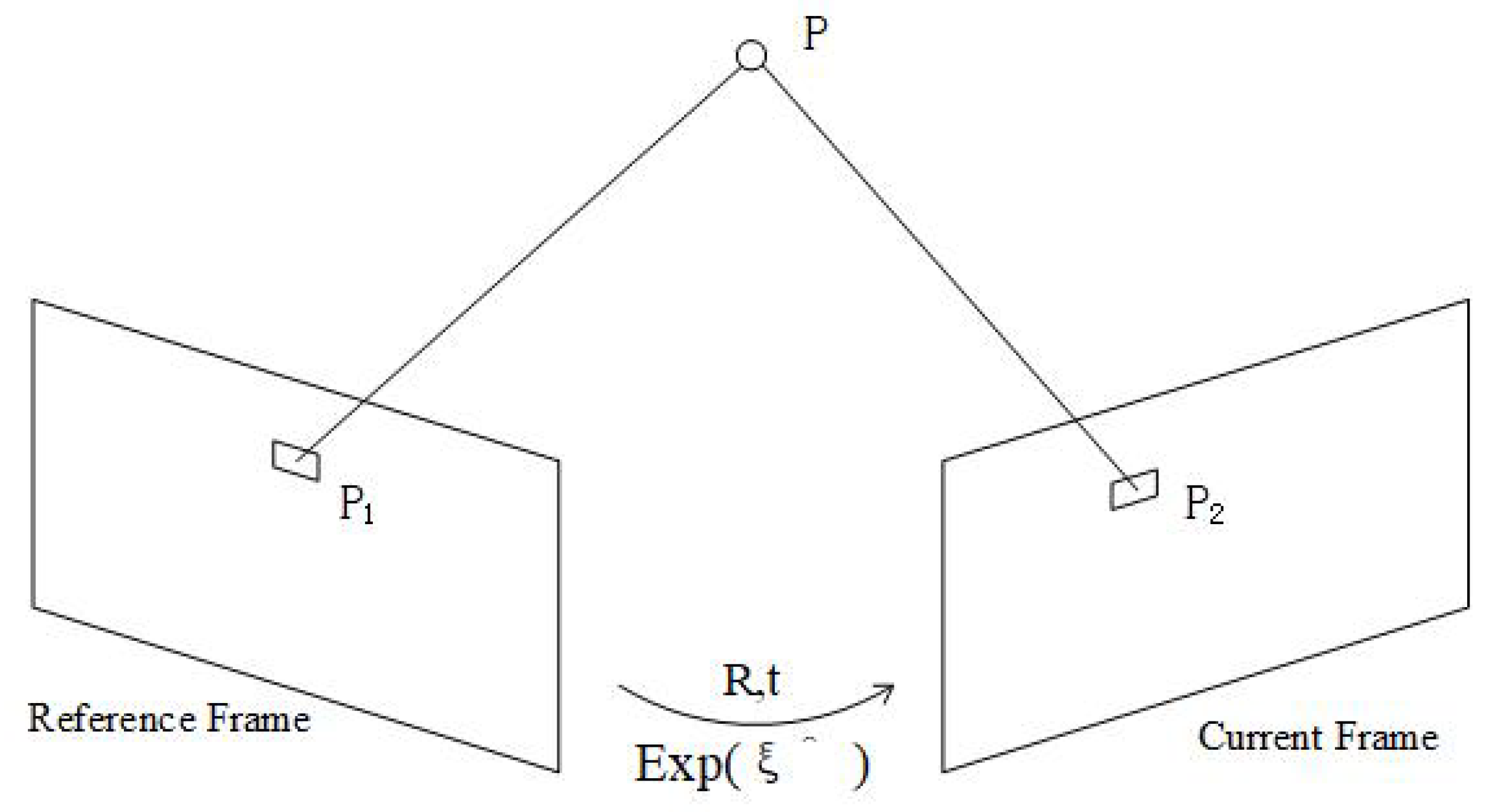
2.2. Pose Estimation by the Direct Method

To address the fact that the process of feature point extraction and matching in ORB-SLAM2 consumed too much computational resource, we used the direct method to estimate the camera’s pose.
In the ORB-SLAM2 system, after the visual odometer captures the image sequence from the camera, the image is processed by extracting the Oriented FAST [53] key points, and then the BRIEF [54] descriptors are calculated for the next step of matching the feature points between frames. When the matching is completed, the camera’s pose can be solved by using the opposite pole geometry or the perspective-n-point (PnP) method [55,56,57]. In contrast, the direct method used in our framework also extracted key points from the image but skipped the steps of calculating the descriptors and using the matched feature points for pose-solving.
The direct method for the pose solution procedure was proposed and developed some time ago [58], and the process we used for the pose solution was similar to the process used in SVO [17]. As shown in Figure 3, the approach uses the initial key frame as a reference frame, then extends a feature point P 1 obtained in the reference frame to a position in 3D space with the same depth as the corresponding map point. The extension point at that position is P. Then the extension point P is projected onto a new frame, the current frame, and the corresponding projection point P 2 on the current frame is obtained. The equations for the projections of the two points are shown in Equations (1) and (2):
P 1 = D 1 Z 1 K P
P 2 = D 1 Z 2 K ( R P + t ) = D 1 Z 2 K e x p ( ξ ^ ) P
where point P is the extension point in 3D space, Z 1 and Z 2 are the depth coordinate values of the extended point P in 3D space in the reference frame and current frame coordinate system, K is the internal reference of the camera, ξ is the Lie algebra [59] of the camera pose R and t, and D is the conversion matrix of the chi-square to non-chi-square coordinates in Equation (3):
D = 1 0 0 0 1 0
In the direct method, the photometric error between the two projection points P 1 and P 2 is used as the basis for optimizing the camera pose, and the equation for calculating the photometric error is shown in Equation (4):
e = I 1 ( P 1 ) I 2 ( P 2 )
Under the assumption of constant gray-scale, numerous feature points are taken to optimize the two-parameter number of this error, and the whole problem of estimating the camera pose becomes Equation (5):
m i n J ( ξ ) = i = 1 N e i T e i
Solving this optimization problem means solving the variation relationship between the error e and camera pose ξ . The Jacobian matrix of the error with respect to the pose Lie algebra can be derived after using the perturbation model of the Lie algebra. The Jacobian matrix is shown in Equation (6):
J = I 2 u u δ ξ
where I 2 / u is the pixel gradient at u, and u / δ ξ , which is shown in Equation (7), is the product of the derivative of the projection equation with respect to the 3D point in the camera coordinate system and the derivative of the transformed 3D point with respect to the transform in two terms:
u δ ξ = f x Z 0 f x X Z 2 f x X Y Z 2 f x + f x X 2 Z 2 f x Y Z 0 f y Z f y Y Z 2 f y f y Y 2 Z 2 f y X Y Z 2 f y X Z
Finally, the Gauss–Newton method, which is shown in Equation (8), is used to iteratively solve for the estimated camera pose information:
( i = 1 N J i T J i ) δ ξ * = i = 1 N J i T e i
The direct method of solving the camera pose has a significant speed advantage over the feature point method.

2.3. Semantic Segmentation

The CNN prediction model was implemented in the C++-based framework CAFFE [60], which was better embedded into the SLAM system. The lightweight network BiSeNetV2 [46] was used as our semantic segmentation network. The network structure of BiSeNetV2 is termed a bilateral segmentation network, and the entire network is divided into two branches: the semantic branch and the detail branch. The semantic branch has a deep layer and narrow channel count, which allows for fast downsampling and more contextual semantic information, and the narrow channel count facilitates speed. The detail branch is the opposite, with a shallow layer and wide channels, so that attention can be focused on local details to reduce the loss of detail. Finally, the features of the two branches are merged by a designed bootstrap aggregation layer to achieve a complementary fusion of features. This efficient network architecture provides an excellent balance between speed and accuracy. We used this network for our semantic segmentation task and adapted its data loading section to fit the form of our dataset.
BiSeNetV2 accepts the key frames from the front end of the framework and performs a pixel-level semantic segmentation. The pixels of the target object on the key frame image are segmented and colored, while the rest of the background remains in its original RGB color, and thus the key frames are overlapped with semantic information for the next thread to perform semantic mapping.

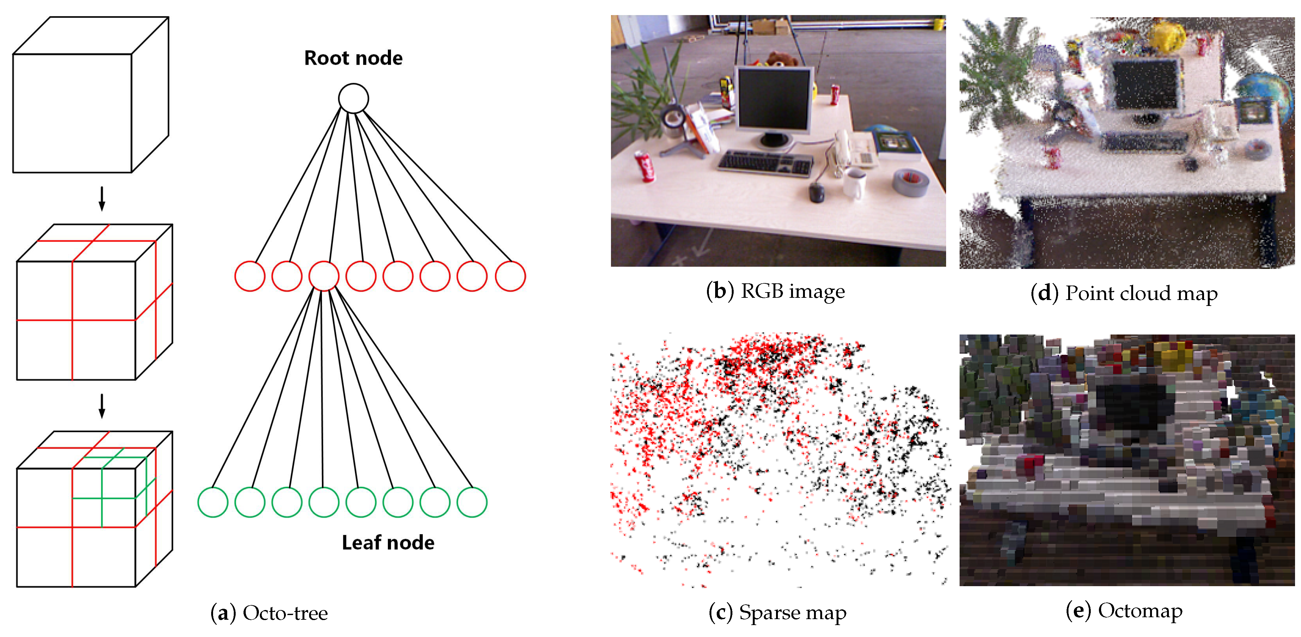
2.4. OctoMap Building

In conventional systems, the dense build map was often represented as a point cloud map, but a dense point cloud map usually required a large storage space, which made it impossible to model large-scale environments with limited memory. Therefore, the OctoMap [47], which is more flexible and efficient in compression and storage compared to the point cloud map, was chosen as our dense map representation. Moreover, the OctoMap can handle moving objects and can be used for navigation tasks. Therefore, the map information generated by our system was stored in an OctoMap.
The principle of the octo-tree is shown in Figure 4. It is a common practice in 3D reconstruction to model a 3D space as many voxels. By cutting each face of a square into two equal slices, the square will then become eight smaller squares of the same size. The process can be seen as expanding a root node into eight leaf nodes. When the process is repeated over and over again, the space is subdivided into smaller spaces, until the highest accuracy of modeling is achieved. We apply this process throughout the whole space, and the resulting map is the OctoMap.
In the octo-tree, information is stored in a node about whether it is occupied or not. When all the leaf nodes of a root node are occupied or not, there is no need to expand the root node. When adding information to the map, the actual objects are often connected together, and the gaps are also connected together, so most root nodes do not need to be expanded to leaf nodes. In contrast, a point cloud map acquires information about every point in an area of space, even if there are no objects in it. Therefore, the octo-tree map representation saves a great deal of storage space compared to a point cloud map.
Among the items of information stored in the node, the log odds is used to quantify the probability of a voxel being occupied. This approach can also be used to reduce the impact of dynamic objects. For example, when using P to represent the probability of a voxel being occupied, the value α of the log odds can be expressed as in Equation (9):
α = l o g i t ( p ) = l o g ( p 1 p )
After the inversion, we have Equation (10):
p = l o g i t 1 ( α ) = 1 1 + e x p ( α )
The result observed for a voxel at time t is denoted by Z t , and the value of the log odds from the beginning to time t is denoted by L ( n | Z 1 : t ) . Then, the value of the log odds for a voxel at time t + 1 is as shown in the Equation (11):
L ( n | Z 1 : t + 1 ) = L ( n | Z 1 : t 1 ) + L ( n | Z t )
This formula indicates that when a voxel is repeatedly observed to be occupied, the log-odds value of that voxel will increase; otherwise, it decreases, and only when the log-odds value of the voxel is greater than a predefined threshold can the voxel be considered occupied and visualized in the OctoMap. Thus, those voxels which are observed to be occupied several times are considered to be stably occupied voxels. Using this approach, the map reconstruction problem in a dynamic environment can be better handled.
The semantic information obtained by the CNN is also incorporated into the OctoMap. The voxels in the OctoMap are associated with several colors, and each color represents a semantic label. For example, the red voxels represent the box and the green voxels represent the door. In this way, the dense semantic OctoMap can provide a basis for UAVs to perform advanced tasks such as understanding scenes and navigation.

2.5. Experimental Setup

A complete semantic mapping system consists of visual SLAM, semantic segmentation, and mapping. Therefore, the proposed system was needed in order to evaluate all these aspects, including the SLAM estimated pose accuracy and the semantic segmentation accuracy. In order to ensure that the system can run in real time on the UAV, the operational performance of the system must also be tested on the UAV platform.

2.5.1. Visual SLAM Pose Accuracy Evaluation

The global dense map generated in real time is obtained by stitching the local map with the solved camera poses, so the accuracy of the global map depends on the accuracy of the camera pose obtained in the visual SLAM system. In our SLAM framework, the direct method was used to accelerate the ORB feature process in the ORB-SLAM2 framework. To ensure that our framework did not lose too much pose accuracy while improving the speed, we selected four representative datasets from the publicly available RGB-D datasets of TUM (Technical University of Munich) [61], to compare the pose accuracy of our framework with the ORB-SLAM2 framework. In the first dataset, RGBD_f3_longhouse, the camera sensor was moved along a large circle through a household and office scene with considerable texture and structure, without too much shaking, for 21.4 m. The end of the trajectory overlapped with the beginning, so that there was a large loop closure. This dataset was used to validate the basic ability of the visual SLAM framework to perform the localization task. In the next dataset, RGBD_f2_kidnap, the camera sensor was artificially obscured several times during a number of 14.7 m runs for testing algorithms that can recover from tracking problems. In the third dataset, RGBD_f2_no_loop, the camera sensor crossed an industrial hall to obtain a 26.1 m long trajectory. The camera sensor did not close the loop at the end, and therefore this dataset could be used to verify the cumulative drift of the SLAM system. In the last dataset, RGBD_f2_hemisphere, the camera sensor was rotated and pointed towards the ceiling several times to verify the robustness of the visual SLAM algorithm in such a violent motion process.
Since the 3D map was created by the key frames selected from all images, in addition to the pose accuracy comparison of all frames, we also performed pose accuracy comparisons for the key frames. Both visual SLAM frameworks were run 5 times on our chosen datasets on a computer with a 3.59 GHz Intel Core CPU and 16 GB of memory.

2.5.2. Self-Built Dataset and Network Training

We used the UAV with a RGB-D camera to acquire a small RGB dataset for an indoor site containing chairs, boxes, and doors. We expected that after training with the semantic segmentation network, the UAV would have the ability to add object-specific semantic information to the map during the next reconstruction experiment in a large indoor scene. The dataset contained a total of 2278 RGB images with a resolution of 960 × 540. We used 1832 images as the training set and the remaining 446 as the test set. We used the LabelMe tool to manually annotate this dataset with ground-truth labels for the three semantic categories of chairs, boxes, and doors.
With the self-built dataset we used four lightweight CNNs: SegNet [28], DeepLabV3+ [32], ICNet [33], and BiSeNetV2 [46] for training, to find the one that best suited our system. Uniformly, for optimization, we used standard stochastic gradient descent with a learning rate of 0.01, a momentum of 0.9, and a weight decay of 5 × 10 4 . We used a batch size of 8 and trained all the networks for 200 epochs on an Nvidia Titan X.

2.5.3. UAV Platform and Operational Performance

To test the performance of the proposed system on a real robot, we built a UAV platform as shown in Figure 5 to conduct flight experiments in a real environment. The UAV was based on a F450 quadrotor airframe, equipped with a Pixhawk running ArduPilot firmware as autopilot, and an XBee radio module for GCS (ground control station) telemetry. The primary payload of the UAV was an embedded AI (artificial intelligence) system, Nvidia Jetson TX2, which was connected to a RealSense D435 camera. The RealSense D435 is an RGB-D camera. It is able to generate RGB images and corresponding depth images. The RealSense D435 was rigidly mounted on the front part of the UAV to capture forward-looking images.
First, to test the real-time capability, the runtime performances of our visual SLAM framework, the ORB-SLAM2, and the four networks were tested on the Nvidia-Jetson-TX2-embedded carrier board on our UAV platform. The embedded carrier board was equipped with a dual-core Nvidia Denver 2 64-bit CPU and a 56-core Nvidia Pascal GPU.
Then, the proposed semantic mapping system was placed on the UAV platform, using the RealSense D435 camera on board as the visual sensor and setting the frame rate of the camera to 30 FPS. The UAV platform performed 5 flight experiments around an indoor site to verify its ability to build the semantic map. The experimental site was about 25 m long, 10 m wide, and 10 m high. Four chairs, six boxes, and two doors were placed in the site as semantic segmentation targets.

3. Experimental Results and Analysis

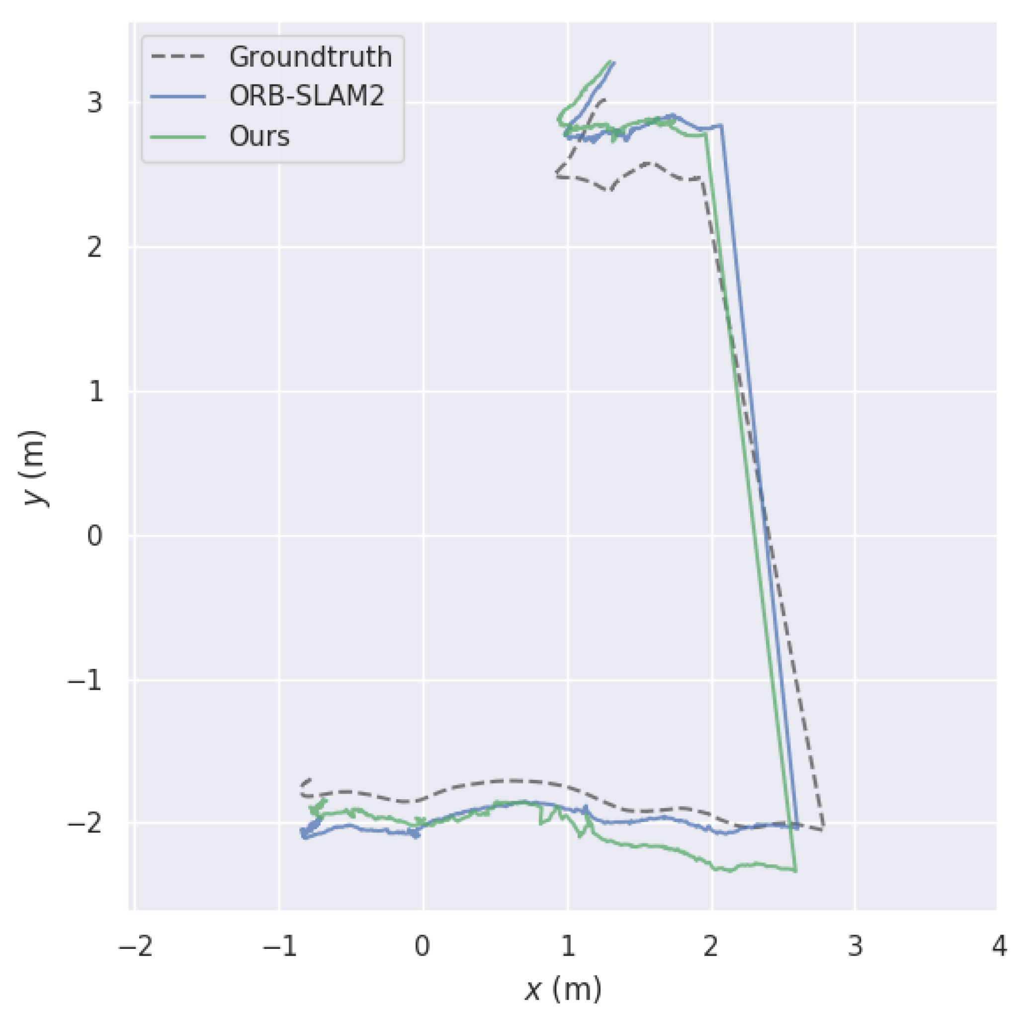
3.1. SLAM Pose Accuracy Evaluation

We used the RMSE (root mean square error) of the ATE (absolute trajectory error) [61] to evaluate the accuracy, and Table 2 shows the error results for the estimated pose of the two visual SLAM algorithms compared to the ground truth. Figure 5, Figure 6, Figure 7 and Figure 8 show the comparison of pose trajectories between the ground truth, the ORB-SLAM2, and the proposed system on the different datasets selected. The blue lines represent the estimated trajectory of the ORB-SLAM2, the green lines represent the estimated trajectory of our method, and the gray dashed lines represent the ground truth.
In the RGBD_f3_longhouse dataset, the camera sensor moved without shaking and the entire motion trajectory occurred in a closed loop. As shown in Figure 6, our system and ORB-SLAM2 maintained an accurate pose estimation in a smooth moving environment, and both showed a global optimization, allowing the whole trajectory to be globally corrected through the loopback detection at the back end of the framework. As shown in Table 2, compared with the ORB-SLAM2, the accuracy of our system was not much degraded.
In the RGBD_f2_kidnap dataset, the camera sensor was artificially occluded halfway through the motion to verify the relocalization capability of the SLAM system after the loss of tracking. As shown in Figure 7, our system and ORB-SLAM2 experienced a loss of tracking after the lens was obscured but accomplished the relocalization at the same location after a long period of lost tracking and continued the task. Our system completed the relocalization simultaneously with the ORB-SLAM2 in the second half, and in the first half of the unlost phase, the smooth movement of the camera sensor highlighted the advantage of the direct method for pose estimation during high-frame-rate motion. Hence, our system showed a considerable improvement in the accuracy of the pose in this dataset, as shown in Table 2.
In the RGBD_f2_noloop dataset, the whole trajectory of the camera sensor had no closed loop, so the SLAM system could not perform loopback detection. This was set up to detect the cumulative error of the SLAM system. As shown in Figure 8, our system and ORB-SLAM2 produced a large cumulative error due to the inability to perform loopback detection, and both deviated from the ground-truth trajectory. The constant camera shake during acquisition of this dataset and the requirement for camera continuity in the direct method resulted in some degradation of the pose accuracy for our system compared to ORB-SLAM2, as shown in Table 2.
In the RGBD_f2_hemisphere dataset, the camera was artificially moved up and down several times during the running process, to verify the robustness of the SLAM system to large dithering. As shown in Figure 9, our system did not deviate much from the global pose estimation, like ORB-SLAM2, but during the large movements of the camera our system often lost track. This was because the direct method has a requirement for camera continuity, which led to a decrease in the pose accuracy of our system in this dataset compared to ORB-SLAM2, as shown in Table 2.
By comparing with ORB-SLAM2, we found that our system had almost the same pose estimation accuracy in an environment with stable camera operation, and our system inherited the same capability as ORB-SLAM2 in terms of relocalization and loopback detection functions. However, in our system we used the direct method to accelerate the feature point extraction and matching process of ORB-SLAM2, which conferred an improvement in the accuracy of our system in high-continuity images but also reduced the robustness of our system in the dithering process.

3.2. Semantic Segmentation Accuracy Evaluation

We evaluated the accuracy of the BiSeNetV2 network used in our system against the accuracy of the SegNet, DeepLabV3+, and ICNet networks on our self-built dataset. Here, we give the following accuracy metrics [62]: IoU (intersection over union) for each class, which is the ratio of the intersection of the true value and predicted value to the union, mIoU, which is the IoU averaged over all classes, and MPA (mean pixel accuracy), which is the proportion of correctly classified pixels out of all ground-truth-labeled pixels, averaged over all classes. As the standard metric for semantic segmentation, IoU was chosen to be evaluated for each classification (box, chair, and door) in our self-built dataset, and the MIoU is also given. In addition, we also give another simple evaluation metric, the MPA, as a reference.
The results of the evaluation for the self-built dataset are summarized in Table 3. We observed that SegNet [28], as one of the classical lightweight semantic segmentation networks, had a better performance on our dataset compared to the 60% mIoU measured on the CamVid dataset [63]. DeepLabV3+ [32] and ICNet [33], as excellent lightweight networks developed in recent years, both show significant improvements over SegNet in terms of accuracy. BiSeNetV2 [46], as the latest lightweight network, has the best performance for both mIoU and MPA evaluation metrics. The increase in mIoU and mPA means that the semantic mapping system has higher accuracy in recognizing specific objects, which is a great help in improving the success rate of intelligent robot tasks. This is an important reason for choosing BiSeNetV2.
We also note that all four networks had better segmentation accuracy performance on our self-built dataset compared to the 60–75% mIoU results generally achieved on the CamVid dataset. This is because the final segmentation accuracy of the semantic segmentation network varies greatly depending on the dataset and parameter settings. The self-built dataset consisted of continuous frames, and the high continuity between frames led to high similarity between images in the training set and test set, so that the desired segmentation accuracy was obtained after training. This also further confirmed the feasibility of applying the semantic information obtained by the CNN in map reconstruction.

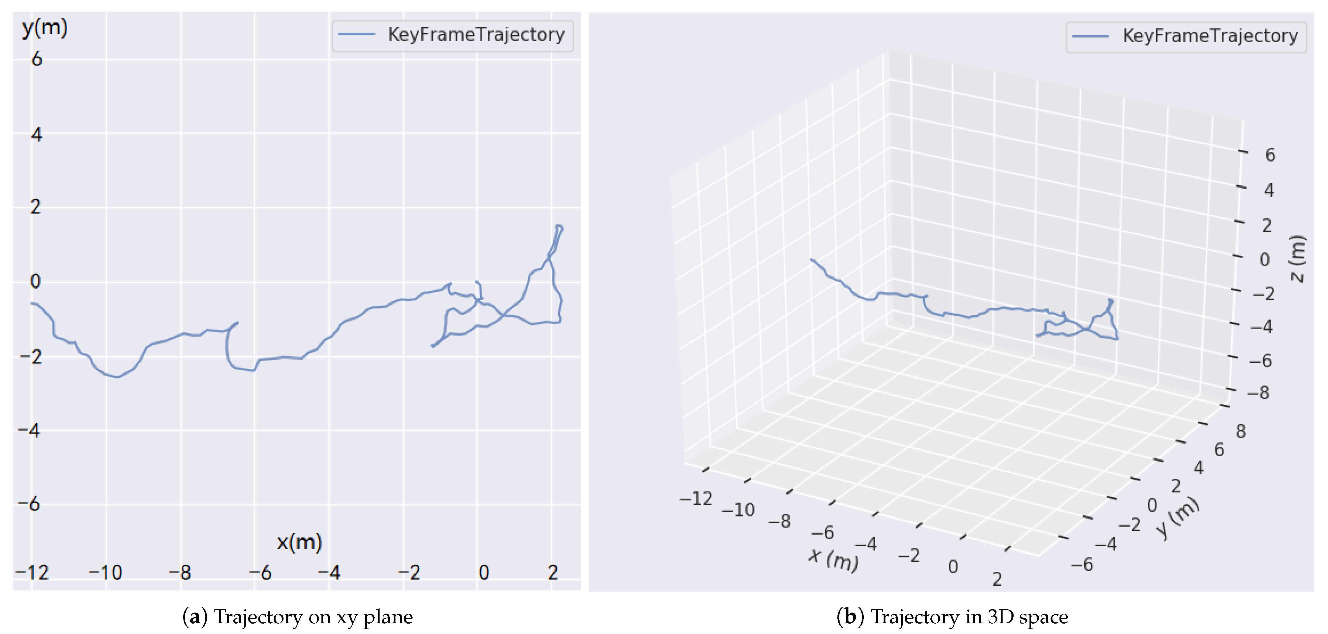
3.3. Operational Performance

Since only the tracking thread at the front end of the ORB-SLAM2 framework is needed to process each frame in real time, and the optimization and loop closing thread at the back end are not, the speed of ORB-SLAM2 mainly depends on its tracking thread at the front end. In our system, the direct method is only used for acceleration in the tracking thread, so we compared the speed before and after the direct method acceleration only in the tracking thread of the original ORB-SLAM2 framework. The results are shown in Table 4.
When the tracking thread at the front end of the system performed frame-to-frame real-time pose tracking, the ORB-SLAM2 [12] framework took an average of 0.09698 ms per frame to track. After using the direct method to accelerate the original framework, the average tracking time per frame was reduced to 0.05777 ms, representing a reduction of approximately 40%.
At the back end of the system for the semantic segmentation task of key frames, SegNet [28], as a classic lightweight network, took an average time of 173.57 ms to segment an image, making it difficult to meet the real-time demand. DeepLabV3+ [32] and ICNet [33], as excellent lightweight networks developed in recent years, dramatically reduced the average time to 53.73 ms and 67.76 ms for a single frame. The latest network, BiSeNetV2 [46], further reduced the average time of a single frame to 34.71 ms, which was sufficient to meet our system’s need for real-time performance. Therefore, BiSeNetV2 was chosen to be the semantic segmentation network of our system.
The trajectory maps of the estimated pose of the UAV platform flying in the experimental site are shown in Figure 10, and the semantic mapping results are shown in Figure 11.
It can be seen from Figure 10 that the UAV did not fly in a straight line. In order to obtain more site information, the UAV turned several times during the flight, and the trajectory was also uneven due to the jitter of the UAV itself.
Figure 11 shows the processing steps of the semantic mapping. During the flight of the UAV, RGB images acquired from different viewpoints entered the system, and the semantic segmentation of specific objects in the images was performed by a back-end semantic segmentation thread. The segmentation result was mapped to the images, and the dense map creation thread completed the reconstruction of the 3D dense OctoMap by using the images with semantic information. The global mapping result over the whole scene demonstrated the ability of our system to achieve large-scale semantic mapping.

4. Discussion

With the growing popularity of deep learning methods, many studies have introduced CNN models to a visual SLAM framework to improve or replace a particular module [8]. Clearly, visual CNN and visual SLAM have different evaluation metrics [62]. The former is evaluated by annotated labels, which are usually based on an offline dataset. In contrast, evaluating the SLAM algorithm requires real-time position information, which can only be captured by external measurement (i.e., a motion capture system). Since this paper targeted large-scene RTSDM, it was difficult to obtain the position ground truth in real time. However we could evaluate the CNN semantic performances and evaluate the SLAM position accuracy separately on the public dataset. Therefore, in Section 3.2 and Section 3.3 we evaluated the semantic accuracy of the selected CNNs on the self-built dataset and compared their computational complexity on the UAV platform. Then, the performance of the SLAM algorithm was evaluated through the public TUM dataset [61], which provides ground-truth pose information from a large motion capture system. The current evaluation did not provide the comparison of pose estimation in a real-time experiment, but this will be investigated in future work.
Notably, in the release of ORB-SLAM3 [13], IMU data were introduced to improve the global accuracy. The introduction of IMU data provides extra pose estimation and will theoretically lead to a considerable improvement in the accuracy of our 3D maps. The remaining problem is whether the computational complexity is acceptable for RTSDM on an embedded platform. Therefore, we will investigate introducing IMU data to the RTSDM framework or renewing the framework on the basis of ORB-SLAM3.

5. Conclusions

We proposed a real-time visual SLAM-based dense 3D semantic reconstruction system. The system acquires image data from an RGB-D camera for pose estimation and 3D map reconstruction. In the pose calculation process, we used the direct method to accelerate the original feature point method, which improves the tracking speed of each frame by about 40%. Next, we used a recent lightweight semantic segmentation CNN, BiSeNetV2, with a mIoU of 89.1 and an average segmentation time of 34.71 ms, to precisely segment the target objects during the UAV task. Finally, we replaced the dense point cloud with a more flexible OctoMap that consumed less memory and could be used for advanced navigation tasks, to further reduce the burden on our system. We tested the performance of the proposed system by using a UAV platform to conduct flight experiments in an indoor site. The frame rate of 12Hz demonstrated that the system has the ability to maintain real-time performance when completing a semantic mapping task.

Author Contributions

Conceptualization, Z.L., J.Z. and F.S.; methodology, Z.L. and X.Z.; software, Z.L.; validation, Z.L. and X.Z.; investigation, Z.L., X.Z. and J.Z; resources, Z.L., S.W. and P.L.; data curation, Z.L., S.W. and P.L.; writing—original draft preparation, Z.L. and J.Z.; writing—review and editing, Z.L. and J.Z.; supervision, J.Z. and F.S.; project administration, F.S.; funding acquisition, F.S. All authors have read and agreed to the published version of the manuscript.

Funding

This research was funded by the National Natural Science Foundation of China, grant numbers 61720106009 and 61773359.

Institutional Review Board Statement

Not applicable.

Informed Consent Statement

Not applicable.

Data Availability Statement

The TUM public dataset used in this study are available at https://vision.in.tum.de/data/datasets/rgbd-dataset/download. The self built dataset used in this study are not publicly available due to the data also forms part of an ongoing study.

Acknowledgments

The authors would like to thank Chenggen Wu, Yang Wang, Pei Gao, Jiong Zheng, Linkun Song, and Delin Pang for helping to build the dataset.

Conflicts of Interest

The authors declare no conflict of interest.

References

  1. Yavuz, D.; Akbıyık, H.; Bostancı, E. Intelligent drone navigation for search and rescue operations. In Proceedings of the 2016 24th Signal Processing and Communication Application Conference (SIU), Zonguldak, Turkey, 16–19 May 2016; IEEE: Piscataway, NJ, USA, 2016; pp. 565–568. [Google Scholar]
  2. Aslan, M.F.; Durdu, A.; Sabanci, K.; Ropelewska, E.; Gültekin, S.S. A comprehensive survey of the recent studies with uav for precision agriculture in open fields and greenhouses. Appl. Sci. 2022, 12, 1047. [Google Scholar] [CrossRef]
  3. Cadena, C.; Carlone, L.; Carrillo, H.; Latif, Y.; Scaramuzza, D.; Neira, J.; Reid, I.; Leonard, J.J. Past, present, and future of simultaneous localization and mapping: Toward the robust-perception age. IEEE Trans. Robot. 2016, 32, 1309–1332. [Google Scholar] [CrossRef] [Green Version]
  4. Ji, Z.; Singh, S. Loam: Lidar odometry and mapping in real-time. In Proceedings of the Robotics: Science and Systems Conference, Berkeley, CA, USA, 12–16 July 2014. [Google Scholar]
  5. Shan, T.; Englot, B. Lego-loam: Lightweight and ground-optimized lidar odometry and mapping on variable terrain. In Proceedings of the 2018 IEEE/RSJ International Conference on Intelligent Robots and Systems (IROS), Madrid, Spain, 1–5 October 2019. [Google Scholar]
  6. Lin, J.; Zhang, F. Loam livox: A fast, robust, high-precision lidar odometry and mapping package for lidars of small fov. In Proceedings of the International Conference on Robotics and Automation (ICRA), virtually, 31 May–31 August 2020; pp. 3126–3131. [Google Scholar]
  7. Di, K.; Wan, W.; Zhao, H.; Liu, Z.; Wang, R.; Zhang, F. Progress and applications of visual slam. J. Geod. Geoinf. Sci. 2019, 2, 38. [Google Scholar]
  8. Jia, Y.; Yan, X.; Xu, Y. A survey of simultaneous localization and mapping for robot. In Proceedings of the 2019 IEEE 4th Advanced Information Technology, Electronic and Automation Control Conference (IAEAC), Chengdu, China, 20–22 December 2019; IEEE: Piscataway, NJ, USA, 2019; Volume 1, pp. 857–861. [Google Scholar]
  9. Aslan, M.F.; Durdu, A.; Yusefi, A.; Sabanci, K.; Sungur, C. A tutorial: Mobile robotics, slam, bayesian filter, keyframe bundle adjustment and ros applications. In Robot Operating System (ROS); Springer: Cham, Switzerland, 2021; pp. 227–269. [Google Scholar]
  10. Klein, G.; Murray, D. Parallel tracking and mapping for small ar workspaces. In Proceedings of the IEEE & Acm International Symposium on Mixed & Augmented Reality, Nara, Japan, 13–16 November 2008. [Google Scholar]
  11. Mur-Artal, R.; Montiel, J.M.M.; Tardos, J.D. Orb-slam: A versatile and accurate monocular slam system. IEEE Trans. Robot. 2015, 31, 1147–1163. [Google Scholar] [CrossRef] [Green Version]
  12. Mur-Artal, R.; Tardós, J. Orb-slam2: An open-source slam system for monocular, stereo, and rgb-d cameras. IEEE Trans. Robot. 2017, 33, 1255–1262. [Google Scholar] [CrossRef] [Green Version]
  13. Campos, C.; Elvira, R.; Rodríguez, J.; Montiel, J.; Tardós, J. Orb-slam3: An accurate open-source library for visual, visual-inertial and multi-map slam. IEEE Trans. Robot. 2021, 37, 1874–1890. [Google Scholar] [CrossRef]
  14. Rublee, E.; Rabaud, V.; Konolige, K.; Bradski, G.R. Orb: An efficient alternative to sift or surf. In Proceedings of the IEEE International Conference on Computer Vision, ICCV 2011, Barcelona, Spain, 6–13 November 2011. [Google Scholar]
  15. Mur-Artal, R.; Tardós, J. Fast relocalisation and loop closing in keyframe-based slam. In Proceedings of the IEEE International Conference on Robotics & Automation, Hong Kong, China, 31 May–7 June 2014. [Google Scholar]
  16. Galvez-Lpez, D.; Tardos, J.D. Bags of binary words for fast place recognition in image sequences. IEEE Trans. Robot. 2012, 28, 1188–1197. [Google Scholar] [CrossRef]
  17. Forster, C.; Pizzoli, M.; Scaramuzza, D. Svo: Fast semi-direct monocular visual odometry. In Proceedings of the IEEE International Conference on Robotics & Automation, Hong Kong, China, 31 May–7 June 2014. [Google Scholar]
  18. Ruso, D.C.; Engel, J.; Cremers, D. Large-scale direct slam for omnidirectional cameras. In Proceedings of the IEEE/RSJ International Conference on Intelligent Robots & Systems, Hamburg, Germany, 28 September–2 October 2015. [Google Scholar]
  19. Gurturk, M.; Yusefi, A.; Aslan, M.F.; Soycan, M.; Durdu, A.; Masiero, A. The ytu dataset and recurrent neural network based visual-inertial odometry. Measurement 2021, 184, 109878. [Google Scholar] [CrossRef]
  20. Yusefi, A.; Durdu, A.; Aslan, M.F.; Sungur, C. Lstm and filter based comparison analysis for indoor global localization in uavs. IEEE Access 2021, 9, 10054–10069. [Google Scholar] [CrossRef]
  21. Newcombe, R.A.; Izadi, S.; Hilliges, O.; Molyneaux, D.; Fitzgibbon, A.W. Kinectfusion: Real-time dense surface mapping and tracking. In Proceedings of the IEEE International Symposium on Mixed & Augmented Reality, Basel, Switzerland, 26–29 October 2012. [Google Scholar]
  22. Newcombe, R.A.; Fox, D.; Seitz, S.M. Dynamicfusion: Reconstruction and tracking of non-rigid scenes in real-time. In Proceedings of the 2015 IEEE Conference on Computer Vision and Pattern Recognition (CVPR), Boston, MA, USA, 7–12 June 2015. [Google Scholar]
  23. Whelan, T.; Leutenegger, S.; Salas-Moreno, R.; Glocker, B.; Davison, A.J. Elasticfusion: Dense slam without a pose graph. In Proceedings of the Robotics: Science & Systems, Rome, Italy, 13–17 July 2015. [Google Scholar]
  24. Matsuki, H.; Scona, R.; Czarnowski, J.; Davison, A.J. Codemapping: Real-time dense mapping for sparse slam using compact scene representations. IEEE Robot. Autom. Lett. 2021, 6, 7105–7112. [Google Scholar] [CrossRef]
  25. Bloesch, M.; Czarnowski, J.; Clark, R.; Leutenegger, S.; Davison, A.J. Codeslam—Learning a compact, optimisable representation for dense visual slam. In Proceedings of the IEEE Conference on Computer Vision and Pattern Recognition, Salt Lake City, UT, USA, 18–23 June 2018; pp. 2560–2568. [Google Scholar]
  26. Loo, S.Y.; Mashohor, S.; Tang, S.H.; Zhang, H. Deeprelativefusion: Dense monocular slam using single-image relative depth prediction. In Proceedings of the 2021 IEEE/RSJ International Conference on Intelligent Robots and Systems (IROS), Prague, Czech Republic, 27 September–1 October 2021; IEEE: Piscataway, NJ, USA, 2020; pp. 6641–6648. [Google Scholar]
  27. Long, J.; Shelhamer, E.; Darrell, T. Fully convolutional networks for semantic segmentation. IEEE Trans. Pattern Anal. Mach. Intell. 2015, 39, 640–651. [Google Scholar]
  28. Badrinarayanan, V.; Kendall, A.; Cipolla, R. Segnet: A deep convolutional encoder-decoder architecture for image segmentation. IEEE Trans. Pattern Anal. Mach. Intell. 2017, 39, 2481–2495. [Google Scholar] [CrossRef] [PubMed]
  29. Chen, L.-C.; Papandreou, G.; Kokkinos, I.; Murphy, K.; Yuille, A.L. Semantic image segmentation with deep convolutional nets and fully connected crfs. arXiv 2014, arXiv:1412.7062. [Google Scholar]
  30. Chen, L.C.; Papandreou, G.; Kokkinos, I.; Murphy, K.; Yuille, A.L. Deeplab: Semantic image segmentation with deep convolutional nets, atrous convolution, and fully connected crfs. IEEE Trans. Pattern Anal. Mach. Intell. 2018, 40, 834–848. [Google Scholar] [CrossRef] [PubMed] [Green Version]
  31. Chen, L.C.; Papandreou, G.; Schroff, F.; Adam, H. Rethinking atrous convolution for semantic image segmentation. arXiv 2017, arXiv:1706.05587. [Google Scholar]
  32. Chen, L.-C.; Zhu, Y.; Papandreou, G.; Schroff, F.; Adam, H. Encoder-decoder with atrous separable convolution for semantic image segmentation. In Proceedings of the European Conference on Computer Vision (ECCV), Munich, Germany, 8–14 September 2018. [Google Scholar]
  33. Zhao, H.; Qi, X.; Shen, X.; Shi, J.; Jia, J. Icnet for real-time semantic segmentation on high-resolution images. arXiv 2017, arXiv:1704.08545. [Google Scholar]
  34. Yu, C.; Wang, J.; Peng, C.; Gao, C.; Yu, G.; Sang, N. Bisenet: Bilateral segmentation network for real-time semantic segmentation. In Proceedings of the European Conference on Computer Vision (ECCV), Munich, Germany, 8–14 September 2018; pp. 325–341. [Google Scholar]
  35. Milz, S.; Arbeiter, G.; Witt, C.; Abdallah, B.; Yogamani, S. Visual slam for automated driving: Exploring the applications of deep learning. In Proceedings of the IEEE Conference on Computer Vision and Pattern Recognition (CVPR) Workshops, Salt Lake City, UT, USA, 18–23 June 2018. [Google Scholar]
  36. Mccormac, J.; Handa, A.; Davison, A.; Leutenegger, S. Semanticfusion: Dense 3d semantic mapping with convolutional neural networks. In Proceedings of the 2017 IEEE International Conference on Robotics and Automation (ICRA), Singapore, 29 May–3 June 2016. [Google Scholar]
  37. Runz, M.; Agapito, L. Co-fusion: Real-time segmentation, tracking and fusion of multiple objects. In Proceedings of the 2017 IEEE International Conference on Robotics and Automation (ICRA), Singapore, 29 May–3 June 2017. [Google Scholar]
  38. Runz, M.; Buffier, M.; Agapito, L. Maskfusion: Real-time recognition, tracking and reconstruction of multiple moving objects. In Proceedings of the 2018 IEEE International Symposium on Mixed and Augmented Reality (ISMAR), Munich, Germany, 16–20 October 2018. [Google Scholar]
  39. He, K.; Gkioxari, G.; Dollár, P.; Girshick, R. Mask r-cnn. In Proceedings of the IEEE International Conference on Computer Vision, Venice, Italy, 22–29 October 2017; pp. 2961–2969. [Google Scholar]
  40. Wu, S.-C.; Tateno, K.; Navab, N.; Tombari, F. Scfusion: Real-time incremental scene reconstruction with semantic completion. In Proceedings of the 2020 International Conference on 3D Vision (3DV), Fukuoka, Japan, 25–28 November 2020; pp. 801–810. [Google Scholar]
  41. Li, X.; Belaroussi, R. Semi-dense 3d semantic mapping from monocular slam. arXiv 2016, arXiv:1611.04144. [Google Scholar]
  42. Dang, Y.; Chen, P.; Liang, R.; Huang, C.; Tang, Y.; Yu, T.; Yang, X.; Cheng, K.T. Real-time semantic plane reconstruction on a monocular drone using sparse fusion. IEEE Trans. Veh. Technol. 2019, 68, 7383–7391. [Google Scholar] [CrossRef]
  43. Qin, T.; Li, P.; Shen, S. Vins-mono: A robust and versatile monocular visual-inertial state estimator. IEEE Trans. Robot. 2018, 34, 1004–1020. [Google Scholar] [CrossRef] [Green Version]
  44. Redmon, J.; Farhadi, A. Yolo9000: Better, faster, stronger. arXiv 2016, arXiv:1612.08242. [Google Scholar]
  45. Yu, C.; Liu, Z.; Liu, X.; Xie, F.; Yang, Y.; Wei, Q.; Fei, Q. Ds-slam: A semantic visual slam towards dynamic environments. In Proceedings of the 2018 IEEE/RSJ International Conference on Intelligent Robots and Systems (IROS), Madrid, Spain, 1–5 October 2018. [Google Scholar]
  46. Yu, C.; Gao, C.; Wang, J.; Yu, G.; Shen, C.; Sang, N. Bisenet v2: Bilateral network with guided aggregation for real-time semantic segmentation. Int. J. Comput. Vis. 2021, 129, 3051–3068. [Google Scholar] [CrossRef]
  47. Hornung, A.; Wurm, K.M.; Bennewitz, M.; Stachniss, C.; Burgard, W. Octomap: An efficient probabilistic 3d mapping framework based on octrees. Auton. Robot. 2013, 34, 189–206. [Google Scholar] [CrossRef] [Green Version]
  48. Nieto, J.; Guivant, J.; Nebot, E. Denseslam: Simultaneous localization and dense mapping. Int. J. Robot. Res. 2006, 25, 711–744. [Google Scholar] [CrossRef]
  49. Zhang, B.; Zhu, D. A stereo slam system with dense mapping. IEEE Access 2021, 9, 151888–151896. [Google Scholar] [CrossRef]
  50. Pizzoli, M.; Forster, C.; Scaramuzza, D. Remode: Probabilistic, monocular dense reconstruction in real time. In Proceedings of the 2014 IEEE International Conference on Robotics and Automation (ICRA), Hong Kong, China, 31 May–7 June 2014; IEEE: Piscataway, NJ, USA, 2014; pp. 2609–2616. [Google Scholar]
  51. Hermans, A.; Floros, G.; Leibe, B. Dense 3d semantic mapping of indoor scenes from rgb-d images. In Proceedings of the 2014 IEEE International Conference on Robotics and Automation (ICRA), Hong Kong, China, 31 May–7 June 2014; pp. 2631–2638. [Google Scholar]
  52. Henry, P.; Krainin, M.; Herbst, E.; Ren, X.; Fox, D. Rgb-d mapping: Using depth cameras for dense 3d modeling of indoor environments. In Experimental Robotics; Springer: Berlin/Heidelberg, Germany, 2014; pp. 477–491. [Google Scholar]
  53. Rosten, E. Machine learning for very high-speed corner detection. In Proceedings of the ECCV’06, Graz, Austria, 7–13 May 2006. [Google Scholar]
  54. Calonder, M.; Lepetit, V.; Strecha, C.; Fua, P. Brief: Binary robust independent elementary features. In Proceedings of the Computer Vision—ECCV 2010, 11th European Conference on Computer Vision, Proceedings Part IV, Heraklion, Greece, 5–11 September 2010. [Google Scholar]
  55. Gao, X.-S.; Hou, X.-R.; Tang, J.; Cheng, H.-F. Complete solution classification for the perspective-three-point problem. IEEE Trans. Pattern Anal. Mach. Intell. 2003, 25, 930–943. [Google Scholar]
  56. Lepetit, V.; Moreno-Noguer, F.; Fua, P. Epnp: An accurate o (n) solution to the pnp problem. Int. J. Comput. Vis. 2009, 81, 155. [Google Scholar] [CrossRef] [Green Version]
  57. Penate-Sanchez, A.; Andrade-Cetto, J.; Moreno-Noguer, F. Exhaustive linearization for robust camera pose and focal length estimation. IEEE Trans. Pattern Anal. Mach. Intell. 2013, 35, 2387–2400. [Google Scholar] [CrossRef] [Green Version]
  58. Irani, M.; Anandan, P. About direct methods. In International Workshop on Vision Algorithms; Springer: Berlin/Heidelberg, Germany, 1999; pp. 267–277. [Google Scholar]
  59. Varadarajan, V.S. Lie Groups, Lie Algebras, and Their Representations; Springer Science & Business Media: Berlin, Germany, 2013; Volume 102. [Google Scholar]
  60. Jia, Y.; Shelhamer, E.; Donahue, J.; Karayev, S.; Long, J.; Girshick, R.; Guadarrama, S.; Darrell, T. Caffe: Convolutional architecture for fast feature embedding. In Proceedings of the 22nd ACM international conference on Multimedia, Orlando, FL, USA, 3–7 November 2014; pp. 675–678. [Google Scholar]
  61. Sturm, J.; Engelhard, N.; Endres, F.; Burgard, W.; Cremers, D. A benchmark for the evaluation of rgb-d slam systems. In Proceedings of the 2012 IEEE/RSJ International Conference on Intelligent Robots and Systems (IROS), Vilamoura-Algarve, Portugal, 7–12 October 2012. [Google Scholar]
  62. Garcia-Garcia, A.; Orts-Escolano, S.; Oprea, S.; Villena-Martinez, V.; Garcia-Rodriguez, J. A review on deep learning techniques applied to semantic segmentation. arXiv 2017, arXiv:1704.06857. [Google Scholar]
  63. Brostow, G.J.; Fauqueur, J.; Cipolla, R. Semantic object classes in video: A high-definition ground truth database. Pattern Recognit. Lett. 2009, 30, 88–97. [Google Scholar] [CrossRef]
Figure 1. Dense semantic mapping: The figure shows an example of our system. The RGB images and depth images are used to reconstruct 3D environments, and the door, box, and chair in the RGB images are colored with respect to semantic information in green, red, and blue, respectively, by semantic segmentation. Finally, the semantic information is combined with the 3D reconstructed map and presented in the form of an OctoMap.
Machines 10 00285 g001
Figure 2. The framework of our system. The blue boxes represent the important data to be processed in the system, the red boxes represent the new parts added to the original framework, and the white boxes include the local mapping thread, loop closing thread, and place recognition parts, which are the same as ORB-SLAM2.
Machines 10 00285 g002
Figure 3. Direct Method. By minimizing photometric errors between the reference frame and the current frame, the poses e x p ( ξ ^ ) are constantly optimized, resulting in very fast speeds as the time for calculating the feature point descriptors is eliminated.
Machines 10 00285 g003
Figure 4. Explanation of the octo-tree method and its properties.(a) Octo-tree: just as a tree root can grow leaves, a large voxel can be subdivided into multiple small voxels, and the 3D space composed of multiple voxels can also be subdivided to present more information [47]. (b) RGB input image: an example input image in the public dataset TUM [61]. (c) Sparse map: a map composed of sparse feature points in the original ORB-SLAM2 [12] as input to (b). Clearly, it is difficult for humans to recognize the map content. (d) Point cloud map: a form of dense map generated using the images in (b). Humans can recognize the map content, but the large storage space and inability to navigate make it unsuitable for small intelligent robots. (e) OctoMap: the dense map form used by our system, which is computationally economic and also efficient for navigation [47].
Machines 10 00285 g004
Figure 5. Our UAV platform equipped with several sensors.
Machines 10 00285 g005
Figure 6. The comparison of the trajectories for the ground truth, ORB-SLAM2, and our method on dataset RGBD_f3_longhouse.
Machines 10 00285 g006
Figure 7. The comparison of the trajectories for the ground truth, ORB-SLAM2, and our method on dataset RGBD_f2_kidnap.
Machines 10 00285 g007
Figure 8. The comparison of the trajectories for ground truth, ORB-SLAM2, and our method on dataset RGBD_f2_no_loop.
Machines 10 00285 g008
Figure 9. The comparison of the trajectories for ground truth, ORB-SLAM2, and our method on dataset RGBD_f2_hemisphere.
Machines 10 00285 g009
Figure 10. The estimated trajectories in 2D/3D space. Note: the mapping system only uses key frames for reconstruction, so only the trajectories of key frames on the xy plane and in 3D space are displayed.
Machines 10 00285 g010
Figure 11. Processing steps and results for the proposed RTSDM. The input images in (a) were acquired by the camera and entered into the system for 2D semantic segmentation as shown in (b), the semantic information was superimposed on the input images as shown in (c), then the system built the local 3D maps of the input images as shown in (d). Finally, the 3D semantic mapping result over the experimental site as shown in (e) was obtained by stitching the pose information.
Machines 10 00285 g011
Table 1. Semantic mapping systems related to our system.
MethodLarge ScaleDense MapComputational Economic
Semantic Fusion [36]
Co-Fusion [37]
Mask Fusion [38]
Xupeng’s [41]
Yuanjie’s [42]
DS-SLAM [45]
Ours
Table 2. The RMSE of the ATE (m) for all frames and key frames of two frameworks.
MethodATE
ORB-SLAM2OursORB-SLAM2_KOurs_K
RGBD_f3_longhouse0.01120.01510.01040.0145
RGBD_f2_kidnap0.08040.04170.05540.0344
RGBD_f2_no_loop0.26940.25770.31870.3320
RGBD_f2_hemisphere0.12630.13930.12040.1403
Table 3. Semantic segmentation results (%) for each class on self-built dataset.
Segmentation MethodIoU_BoxIoU_ChairIoU_DoormIoUmPA
SegNet72.789.781.880.089.3
ICNet84.494.782.785.988.8
DeepLabV3+83.191.883.885.392.1
BiSeNetV286.395.588.189.194.1
Table 4. Runtime test results (ms) per frame on the UAV platform.
ModuleVisual SLAMCNN
ThreadTrackingSemantic Segmentation
Time(ms)ORB-SLAM296.98SegNet173.57
ICNet67.76
Ours57.77DeepLabV3+53.73
BiSeNetV234.71
Publisher’s Note: MDPI stays neutral with regard to jurisdictional claims in published maps and institutional affiliations.

