Article

Integration of Design, Manufacturing, and Service Based on Digital Twin to Realize Intelligent Manufacturing

1
School of Economics and Management, Shanghai Maritime University, Shanghai 201306, China
2
School of Computer and Information Engineering, Henan University of Economics and Law, Zhengzhou 450016, China
3
China Institute of FTZ Supply Chain, Shanghai Maritime University, Shanghai 201306, China
4
College of Electronics and Information Engineering, Tongji University, Shanghai 201804, China
5
Shanghai Institute of Intelligent Science and Technology, Tongji University, Shanghai 201804, China
*
Author to whom correspondence should be addressed.
Machines 2022, 10(4), 275; https://doi.org/10.3390/machines10040275
Submission received: 24 February 2022 / Revised: 3 April 2022 / Accepted: 7 April 2022 / Published: 12 April 2022
(This article belongs to the Special Issue Digital Twin Applications in Smart Manufacturing)

Abstract

:
Complex product design, manufacturing, and service are the key elements of a product’s life cycle. However, the traditional manufacturing processes of design, manufacturing, and service are independent of each other, so lack deep integration. The emergence of digital twins offers an opportunity to accelerate the integration of complex product design, manufacturing, and services. For intelligent manufacturing, physical entity and virtual entity transformation can be realized through digital information. A collaborative framework for complex product design, manufacturing, and service integration based on digital twin technology was proposed. The solutions of process integration, data flow, modeling and simulation, and information fusion were analyzed. The core characteristics and key technologies of service-oriented manufacturing, design for service and manufacturing, and manufacturing monitoring based on the deep integration of the digital twin were discussed. Finally, the feasibility of the framework was verified by a self-balancing multistage pump manufacturing case. The performance of the upgraded pump under the framework was tested, and the test results proved the effectiveness of the integrated framework.

1. Introduction

With the integration of the new generation of information technology (NGIT) and the traditional manufacturing industry, the market demand for customization and personalization is increasing [1]. Different from traditional manufacturing, intelligent manufacturing (IM) focuses on the product lifecycle (PLC) [2]. Based on advanced technology, intelligent perception realizes intelligent design, manufacturing, and service, which is the deep integration of information and intelligent technology [3].The fierce competition of globalization and the demand for customization has led to a shortening of PLC, necessitating a rapid response to market fluctuations [4]. IM is the general trend of full integration of information technology applications with industrialization. It can incorporate multiple domains, encourages collaboration between departments, and leads to a high level of integration.
With the development of information technologies and advanced manufacturing technologies, the digitalization of PLC is accelerating [5]. Digital advances provide new ways to optimize the design process, shorten the PLC, and produce products that better meet market needs [6]. In PLC, the focus is on design, manufacturing, and service (DMS). Focus on the scope, mainly complex products. Complex products have the characteristics of multiple crossdisciplines, multiple collaborative departments, and high integration. Its design manufacturing and service are an extremely complex process [3]. As a large amount of multisource heterogeneous data generated by complex products are difficult to directly incorporate, the physical entity (PE) link fracture leads to PLC not being effectively integrated. In this paper, for the complex product design, manufacturing and service, and uses DMS to represent the integration of these three stages.
To deal with these challenges, many scholars have noted the advantages of the integration of DMS with abundant data [7], cases [8], modes [9], integration platforms [10], and simulation systems [11]. With the development of NGIT, more rational layouts, effective integration, and scientific methods are brought together to form an efficient PLC. The possibility of DMS in the virtual entity (VE) was explored through computer-aided engineering [12], digital mock-up [13], computer-aided design software, and virtual manufacturing/ prototypes [14]. These technologies gradually begin to realize the intelligent integration of DMS through the interaction between VE and PE. However, regardless of the computer-aided engineering, digital mock-up, or virtual prototype, all attach great importance to the data in PE. In other words, the study is conducted in ideal situations; the possible and dynamic outcomes of the PE are not tracked in realtime, resulting in the results deviating from real situations. Therefore, the links in PLC still have different degrees of disconnection in the previous study. The large amount of data directly generated by PLC is not in realtime, and so often cannot be integrated effectively. This leads to the repeatability of information being low, dynamic feedback ability being in sufficient, and information islands forming. The cycle iteration and integration innovation within the PLC cannot be effectively realized. The integrated framework system proposed in this paper tries to solve the current confusion. In addition, the current research on DMS integration for complex products is relatively scant, so we cannot meet the requirements of an NGIT background. Therefore, the possibility of integrating DMS between VE and PE should be studied to eliminate the limitations only based on PE to improve the efficiency of DMS in the context of NGIT.
The emergence of the digital twin (DT) [15] offers an opportunity to eliminate the mentioned obstacles [16]. DT is a concept that has origins from PLC [17]. In the broad context of CPS, the DT paradigm fits in well with the PLC perspective [18]. As a kind of advanced technology that makes full use of models, data, and multidisciplinary integration, DT is an important starting point for realizing the deep integration of information. It provides an effective means of integration innovation in IM [19]. In particular, DT is more than just pure data; it also includes models and algorithms, which ensure a maximum concordance between PE and VE [20]. DT applies to different links of PLC, such as design, manufacturing, and service [21], and can provide realtime and accurate perception, dynamic control, and information services for IM. Therefore, it is possible to transfer from traditional, expensive physical trials to DT-based digital trials. DT has become a reality in many fields, such as the DT shop-floor, biotechnology, logistics, and construction [22]. Therefore, a framework for DMS-DT is proposed in this paper. Therefore, the research scope of this paper focuses on the manufacturing field of complex products. For complex products with high research and development (R&D) costs, large scale, high technical content, single or small batch customization, and high integration degree, the DMS-DT integration framework is proposed.
This paper is structured as follows: Section 2 reviews related works, including those on DMS, PLC, and DT. Section 3 introduces the DMS integration system from the perspective of DT. A DMS collaborative integration framework based on a DT driver is constructed. Section 4 elaborates on the operation of the mode of DMS integration driven by DT, discussing the core characteristics and key technologies of the actual process. Section 5 presents the development and application of a self-balancing multistage pump that verifies the scientific and feasibility of the model. The conclusions and prospects for future research are presented in Section 6, which provides theoretical and practical support for the further development and application of DT toward IM.

2. Literature Review

There were two key concepts mentioned in the introduction, namely DMS and DT. To realize the integration of PLC, design, manufacturing, and service are the most important links. Complex product design is the first stage of IM, which can provide support for manufacturing, processing, equipment, service, operations and maintenance. To realize the integration of DMS-DT, the research process of the integration of DMS should be determined first. DT is an important starting point to achieving the objective of IM. DT and DMS try to build more rapid or more accurate models to advance IM. This section will involve an overall review of the relevant literature to highlight the research focus of this paper.

2.1. Integration of PLC

To solve the scientific problem of PLC deep integration, many experts and scholars have worked on PLC management optimization, resource allocation, data circulation, product design manufacturing service operation maintenance decommissioning, and other stages of mutual integration. With the trend of IM accelerating to information, network and intelligence, PLC increasingly reflects any restrictions of the different links. The traditional linear and serial product development process is unable to meet the urgent needs of innovation development in IM. Tao et al. [23] proposed a product design method, product manufacturing method, and product service method driven by DT to make full use of cyber-physical data to serve PLC. In particular, the model and case study of the three stages is independent. Da Luz et al. [24] proposed a methodology for lifecycle assessment through an assessment matrix that considers the impact categories and the phases of PLC. Myrodia et al. [25] developed a configuration lifecycle management maturity model that can be used to accomplish the integration of organizational knowledge and tools. This research has some reference significance for the integration research on DMS in this paper. Bicocchi et al. [26] discussed the architecture of digital factories and proposed a service-oriented and data-sharing architecture framework. Kong et al. [27] constructed a multilayer PLC integrated framework for low-carbon parts design with consideration of design characteristics, processing technology, processing characteristics, operation characteristics, and carbon emission characteristics. Uysal et al. [28] combined intelligent digital mesh, enterprise architecture, and software product line engineering approaches to produce an IM development framework. Kleinekorte et al. [29] proposed a lifecycle assessment approach for the chemical industry, extending the scope to the process, the product itself, and the supply chain. To realize data information sharing of PLC, Mandolini et al. [30] tried to define a standard model of lifecycle data. Li et al. [31] proposed a multiproduct lifecycle remanufacturing system and reviewed it.
Reviewing the mentioned literature, we see that PLC has made some achievements in theoretical research and the practical application of related theories and technologies. However, most of these studies separate design, manufacturing, and service in PLC, resulting in unit isolation, data fragmentation, and system integration stagnation, and they fail to fully tap the potential of PLC for manufacturing enterprises. Moreover, the existing achievements cannot fully meet the requirements of PLC integration against the backdrop of NGIT. Therefore, new methods are urgently needed to promote the deep integration of PLC, especially DMS to promote the overall upgrade of PLC.

2.2. Model of DT

DT is defined as a technique capable of digital mapping and virtual model construction of all elements, such as structure, function, material, geometric parameters, process state, etc. [32]. DT technology has been widely used in aspects of the lifecycle such as collaborative design, assembly and manufacturing, process control, quality control, and so on. To realize the DT, Grieves proposed a universal DT model, called a three-dimensional DT model [17]. It provides a development direction for a DT system to carry out multidisciplinary co-simulation; model lightweight technology accurately and in realtime; and realize the simulation verification and iterative decision making of IM. However, with the continuous enrichment of relevant theories and technologies, as well as the continuous upgrading and innovation of application requirements, the application of DT presents information, data, universality, intelligence, and other requirements. Borangiu et al. [33] proposed a four-dimensional DT model, which covers the data acquisition and transmission module, virtual module, prediction module, and decision module. Redelinghuys et al. [34] proposed a six-dimensional DT model, including physical data sources, local data repositories, data information transformation layers, cloud-based information repositories, and simulation and simulation modules. Tao’s team added two new dimensions of twin data and service to Grieves’ three-dimensional model, proposing a five-dimensional model [35]. Then the concept of DT shop-floor was proposed [36], and a certain base of theoretical and technical support was formed.

2.3. DT Perspectives on PLC

The above basic theoretical research and model construction exploration provides the basis for the practical applications of DT. In this paper, DT chooses PLC as the carrier, and its technology can be applied to PLC stages. We consider that the main stages of PLC are design, manufacturing, and service, because it mainly depends on the above three stages. This section introduces the application status of DT in three stages: design, manufacturing, and service.

2.3.1. Applications in the Design Stage

The deep integration of DT in the design stage promotes the rapid response and dynamic process in the intelligent manufacturing design stage, enriches the design content, and shorts the complex product design cycle. The application of DT in the design stage fully embodies the integration and iterative optimization of the data information model and physical model. Tao et al. [23] believe that DT can take the PLC into account in the design process and make decisions to increase the efficiency of the entire PLC at different design stages. Liu et al. [37] proposed the configuration design-motion planning-control development-optimization decoupling design architecture based on DT, and expounded the iteration logic of a design model. Lai et al. [38] proposed an enabling technology based on DT, and illustrated the shape performance of integrated DT for structural analysis of complex heavy equipment, with a boom crane as an example. Gu et al. [39] believe that DT is powerful for addressing these challenges for requirement conversion, and proposed a DT-driven requirement conversion architecture. The framework is beneficial to customer participation and suitable for the dynamic environment in the design stage. Polini et al. [40] introduced a DT technology to support the lightweight design of assemblies in composite material, and constructed a model framework, information flow, and computing tools for product design. Damjanovic and Behrendt [41] designed a DT demonstrator using an open-source method. In summary, design based on DT can predict the performance of a product or system, identify potential problems, and point out optimization directions, which may not be possible with traditional design.

2.3.2. Applications in the Manufacturing Stage

Traditional manufacturing refers to the industrial process of transforming raw materials into finished products [42]. However, with the improvement of product quality requirements and the rapid development of market response, the manufacturing industry is changing from a primary process to an intelligent process, which is commonly referred to as the transformation to IM [43]. IM requires a closed-loop manufacturing process and data information interaction. The core of DT is to realize the communication and interaction between PE and VE through the data flow.
The technological development represented by DT is a key factor in realizing IM. Wang et al. [2] proposed a DT-based manufacturing framework for the integration of manufacturing and service of complex products. Wu et al. [44] proposed an innovative application model of a DT-driven ship intelligent manufacturing system, focusing on the analysis of the operation mechanism, implementation process, and architecture of the model, thereby providing a reference for enterprise practice. Zhu et al. [45] proposed a DT-based thin-walled part manufacturing system, which can manage and control product progress and changes in realtime. Wang et al. [46] discussed the visualization methods of data information in the product lifecycle and proposed a DT-based visualization framework for flexible manufacturing systems. Guo et al. [47] proposed a flexible cell manufacturing method based on DT. In the method design, decoupling and multi-objective optimization based on event mechanisms are adopted. Tao and Zhang [48] discussed and proposed the concept of the DT shop-floor, which includes four key components: a physical workshop, virtual workshop, workshop service system, and workshop DT data. Park et al. [49] designed an approach based on DT to solve the problem of personalized production and distributed manufacturing systems. This method can trace past data information, store, and call, providing information to support future decisions. Sun et al. [50] proposed a DT-driven method for the assembly and debugging of high-precision products, assembly prediction, and assembly and debugging process optimization. Mykoniatis and Harris [51] described the realization of a DT emulator for the modular production system of automatic mechatronics.

2.3.3. Applications in the Service Stage

In the traditional service stage, products are often scattered and discontinuous, and difficult to track, so it is difficult to uniformly manage, aggregate, and access data. DT for the digital transformation of services offers considerable advantages, including smart scheduled maintenance, realtime monitoring, remote controlling, and predicting functionalities [52]. NASA [53] has studied the fault prediction and elimination method of a complex system model based on DT and has successfully applied it to aircraft and rockets [54]. The AIR Force Research Laboratory has developed an aircraft structural life prediction model based on DT by combining ultra-high-fidelity virtual aircraft with models that influence flight structure deviation and temperature calculation [53]. Tao et al. [55] believe that DT can be used for operation and maintenance prediction, which is helpful to understand the degradation and abnormal events in the manufacturing process. Wang et al. [56] proposed a DT-based recycling system for waste electrical and electronic equipment, which supports PLC manufacturing and remanufacturing. Duan et al. [57] proposed a DT-based monitoring framework to solve the problems of low visual monitoring ability and poor effect of blade rotor test bench, which provides a reference for equipment monitoring. Niu et al. [58] proposed a hybrid method of service-based DT and a digital threading platform to implement advanced manufacturing services using an embedded crowd sourcing mechanism. Zhang et al. [59] designed a new two-layer distributed dynamic shop scheduling architecture based on DT scheduling of shop floor and multibusiness units.
This review found that there are still some problems to be solved to fully explore the potential of DT in IM, although some studies and enterprise practices have explored DT and PLC. Previous studies on DT have mainly focused on product design, production management, and quality control, especially workshop maintenance of major equipment, such as DT shop-floor, equipment life prediction, product status monitoring and fault diagnosis, predictive maintenance, etc. DT technology makes it possible to execute PLC in the VE completely. However, previous research has mainly constructed models for each stage (design, manufacturing, and service) separately. There are few studies on the integration of the three phases, and even fewer on DMS-DT. However, research on DMS integration, especially against the backdrop of NGIT, is necessary for PLC optimization and circulation. Therefore, this paper proposes a DMS-DT integration framework to fill the research gap.

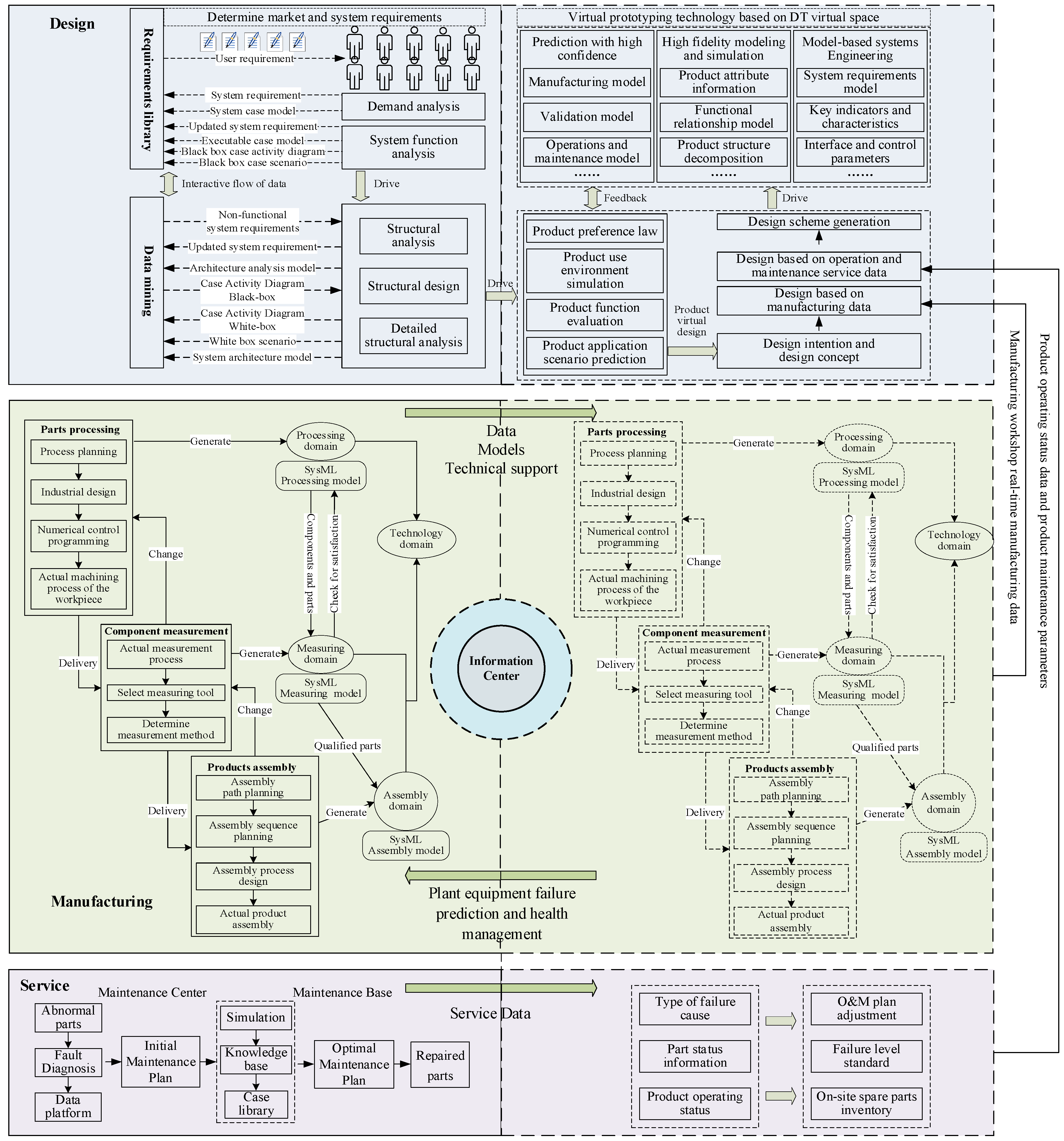
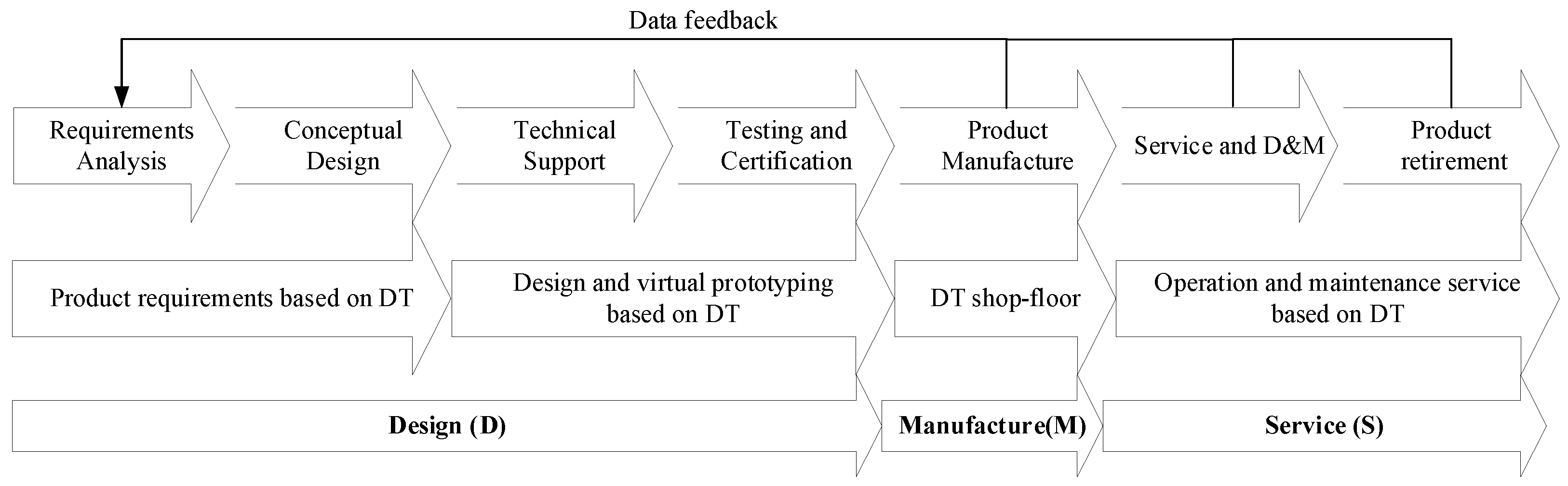
3. Integrated Framework of DMS-DT

Traditionally, design, manufacturing, and service are separate from each other. The manufacturer’s task is completed when the product is delivered to the user. Designers and after-sales services rarely consider the manufacturing information, resulting in a lack of communication between design, manufacturing, and service; it is extremely easy to form an “information island” [2]. Based on the interaction and relationship between DMS and DT, an integrated framework is proposed in this section. DT makes the integration of DMS more concrete, and the technologies involved in the DMS-DT framework more feasible. The role of DT in DMS is mainly reflected in three aspects: complex product design, manufacturing, and service. (See Figure 1.)
The integrated framework mainly includes five modules: Intelligent design module, Manufacturing module, Service module, Virtual space simulation, and Information center. The first three modules constitute DT physical space, corresponding to PE in the five-dimensional DT model. Virtual space simulation constitutes DT virtual space, corresponding to VE in the five-dimensional DT model. Information center corresponds to DD in the five-dimensional DT model. The information link module corresponds to CN in the five-dimensional DT model. With the impetus of DT technology, the integration of PE and VE and in-depth information exchange are realized. By the integration of manufacturing and service based on DT, the data in the data service center is constantly updated to predict product failures and scheduled maintenance plans, guide the intelligent design module to update and improve the design scheme, and realize the transformation and upgrading of DMS.
DT runs through the whole process of PLC: design, verification, manufacturing, and service. It is well known that the concept of DT was originally proposed for PLC and residual life prediction. The integration of DMS can realize the interconnectivity of PLC elements. DT can realize PE-VE mapping of PLC stages. In the design stage, all the influencing factors, including market demand, user comments, cost, etc., can be run by the designer through DT to verify the accuracy of the design prototype. In the manufacturing stage, with the help of the DT shop-floor, the product concept design formed in the design stage can be updated through VE assembly information, quality control information, spatial structure information, and so on. In the service stage, the framework of DMS-DT enables us to enhance users’ satisfaction. Manufacturers and suppliers can provide realtime guidance and operational updates based on user responses and the environment. Furthermore, it can provide predictive services and maintenance for users and intervene before failures occur to improve their overall satisfaction. The specific functions of each plate in the DMS-DT framework are as follows.

3.1. Intelligent Design Module

An intelligent design module follows the traditional design process, including determining requirements, scheme design, technical design, prototype trial production, etc. The traditional complex product design process is verified by a virtual prototype. After the designer submits the design models, drawings, and related documents to the manufacturing department, the design process is completed. Complex product design based on the DMS integration framework is different from traditional design. Manufacturing-based design, and service-based design are all guided in a closed-loop way at this stage. This process of information transmission and fusion is carried out, involves the PE and VE in Figure 1.
Determining the requirements, scheme design, and technical design determines the product’s function and performance. The product development process explores the potential needs of users, creatively using scientific and technological knowledge (such as the literature, patents, technology, etc.) to innovate or improve products in terms of function and structure. These are the basic steps that are synchronized with the traditional design stage. In addition, the intelligent design module involved in the framework in Figure 1 makes manufacturing-based design the basis of R&D. In the manufacturing stage, manufacturing resources such as materials, energy, and technology are processed and utilized through the integration of DMS and DT. Designing new products or innovating and improving on existing products from a manufacturing perspective focus on the product validation stage. After the product’s conceptual design is completed, the DT shop-floor is used to simulate the production process and evaluate the performance of the product prototype based on the coupling characteristics of the material and structure of the prototype. One must pinpoint the defects that do not meet the design requirements and address the defects iteratively. On this basis, the pilot production is carried out in the physical workshop, and the performance of the product is tested to verify whether the prototype meets the design requirements. If not, iterative feedback is required to modify the design draft and revalidate it.
The integration of DMS-DT proposed in this paper covers and absorbs feedback from the service and manufacturing stages into the design, which can further reflect and express the needs of users. One can further improve the flow of data throughout the PLC to improve satisfaction and efficiency. Complex product optimization mainly happens in the prototype testing and production stages, as design engineers can provide geometric dimensions, assembly steps, process rationality, address manufacturing deviation, etc. In this framework, prototype testing and simulation can be completed in the DT virtual space of the intelligent design module. Meanwhile, the service-based design supports the identification or prediction of the operating state, faults, and functions of the complex product, thus supporting the update and optimization of the design.

3.2. Manufacturing Module

Dynamic communication within a manufacturing system plays a decisive role in the timeliness, stability, and reliability of the system. A manufacturing system based on DT can effectively promote the deep integration of information and physics and achieve the purpose of data dynamic interaction. In the integration framework shown in Figure 1, the manufacturing process based on DT involves PE and VE. To analyze the complex logic system and interaction relations in the manufacturing stage, the basic elements of the system and the relationships between the elements should be determined first. In terms of industrial engineering systems theory, the components of a manufacturing system can often be analyzed as people, machines, materials, methods, and environment (4M1E). Factors of production constitute subunits or subsystems, which in turn act as components of more complex systems. The interaction between subunits can be divided into intra-unit interactions and unit diplomatic interactions based on different levels and objects. The former is relatively simple and singular, while the latter is more complicated due to factors such as a wide scope and many participants. Figure 2 lists the common elements and interactions within a manufacturing system.
The manufacturing process, part of the daily production and processing of a workshop, includes the manufacturing equipment, material transportation system, resource allocation, staff, manufacturing environment, and other interactive factors. Production workshop equipment efficiency, operational specifications, performance, material transport efficiency, operator standardization, environmental factors, etc., all require auxiliary monitoring equipment. Thus, there is a need for realtime information tracking and supervision. Monitoring devices can be configured with sensors, controllers, cameras, and sound sensors. For information awareness, data is tracked, collected, stored, and dynamically transmitted to the information center in realtime. Meanwhile, in the VE of DT, entities are transformed into data through the model, including equipment flow, material performance, environmental elements, virtual personnel, etc., combined with the PE model to form the factor relations mapping VE.

3.3. Service Module

Service in PE mainly monitors the normal operation of products and collects service data. It not only collects, analyzes, and uses the data generated in the process, but also adjusts the operation and maintenance plan after receiving feedback from the information center to ensure the normal operation of the complex product. This paper focuses on the complex product service stage, which not only includes the product services provided for customers but also includes the operation, maintenance, repair and service after the product is put into use. It can be understood as a relatively broad concept of service. The data provided by service includes all product running data, component consumption data, component status data, fault causes and classifications, fault degrees and maintenance degrees, and usage of spare parts. The running status of a product refers to whether the product has faults or other unexpected conditions during the operation. Component status information and component loss are important basis for tracking and predicting product failure causes. Information on the fault type, fault level, and fault cause in product operation, as well as data on spare parts preparation, provides an important reference for the virtual service unit to make the operation and maintenance plan. Meanwhile, the service center is an important place that completes parts maintenance tasks. The efficiency of the center directly affects the efficiency of the product service. The service center performs physical maintenance on product components based on the maintenance plan formulated by the virtual service. The service center is divided into product operation field maintenance and maintenance base maintenance according to the maintenance plan of the maintenance mode and maintenance degree of classification. If maintenance is needed on-sites, such as performance testing and parts replacement, itis carried out directly in the production workshop. If maintenance is required at the maintenance base, one can transportation the faulty parts to the maintenance base, e.g., for regular disassembly, system maintenance, and parts replacement.
According to the status parameters and information data obtained from the information center, the simulation is carried out on the parts that need to be monitored and maintained, and then a targeted operations and maintenance scheme is formulated to implement the service of the VE. Based on the related data, relationships, and rules in the knowledge base, the virtual service unit considers the maintenance cost, time cost, resource optimization, process integration, and implementation path to obtain the optimal maintenance plan. Generally speaking, the optimal maintenance plan includes a maintenance path, maintenance degree, maintenance cost, consumed resources, product life, and other information elements. Maintenance is varied and complex in different situations. In the process of product operation, one needs to pay attention to daily maintenance, and may need to replace parts regularly. In the process of service operation and maintenance, some cases need to be handled on site, and some cases need to be returned to the site for handling. After an optimal maintenance plan is developed for the information center, the virtual service unit guides the maintenance unit in the PE to perform physical maintenance according to the optimal maintenance plan. The service unit provides simulated on-site maintenance and optimized maintenance solutions, enabling realtime interaction and integration between a VE and a PE device.

3.4. Virtual Space Simulation

DT rings are virtual rings that correspond to and map to product lifecycle rings. The VE and model established by DT in the user demand stage are called demand DT. The VE and model established in the complex product design stage are called the design DT or product DT and are mainly embodied in complex product virtual prototypes. The workshop production process design model of VE and total factor, called the workshop DT body, includes virtual models of production equipment, process equipment, material virtual prototypes, virtual models of the logistics transportation system, human resources, and virtual prototype models; all elements need to be compatible with each other to ensure coordinated operations and support the effective operation of the workshop production line. In the complex product service stage, the geometric dimensions and manufacturing parameters of a single product generated in the product virtual prototype and manufacturing stage are jointly submitted to users, forming the DT of service, supporting the analysis and judgment of the service status and helping to identify complex product faults and predict performance.

3.5. Information Center

As the data carrier and conversion center of DMS-DT, the information center circulates, stores, and exchanges the information generated by each module. The information center is divided into four core modules: data circulation collection, data storage management, data conversion processing, and data practice application. It collects corresponding data from design plants, manufacturing plants, service systems, and VE. Information centers obtain complex product status data and component status data from services, PLC data from manufacturers, and complex product design parameters from designers. In addition, the information center collates and transforms simulation data from simulation systems in virtual space. After data fusion processing, these data can be uniformly stored in the information center and fed back to each module according to the actual demand to improve the operation and use efficiency of the module. To sum up, the information center not only collects and stores data but also is the overall application and conversion center of PLC data. It can filter and organize data from each module and store it as a knowledge base. The knowledge base can provide a decision reference and a service basis for VE conceptual design, virtual prototype testing, and virtual operation and maintenance scheme formulation. In addition, the PE manufacturing process can be monitored for fault prediction in realtime, which can then guide future product design and service. Importantly, it is the flow of information in the information center that designs the connection scheme and data interaction mechanism to achieve the PE interaction VE. An information center based on DT technology provides a data fusion processing platform for DMS with all elements and processes. The DMS-DT integration effect is realized to eliminate information islands and realize the perfect docking of design, manufacturing, and service.

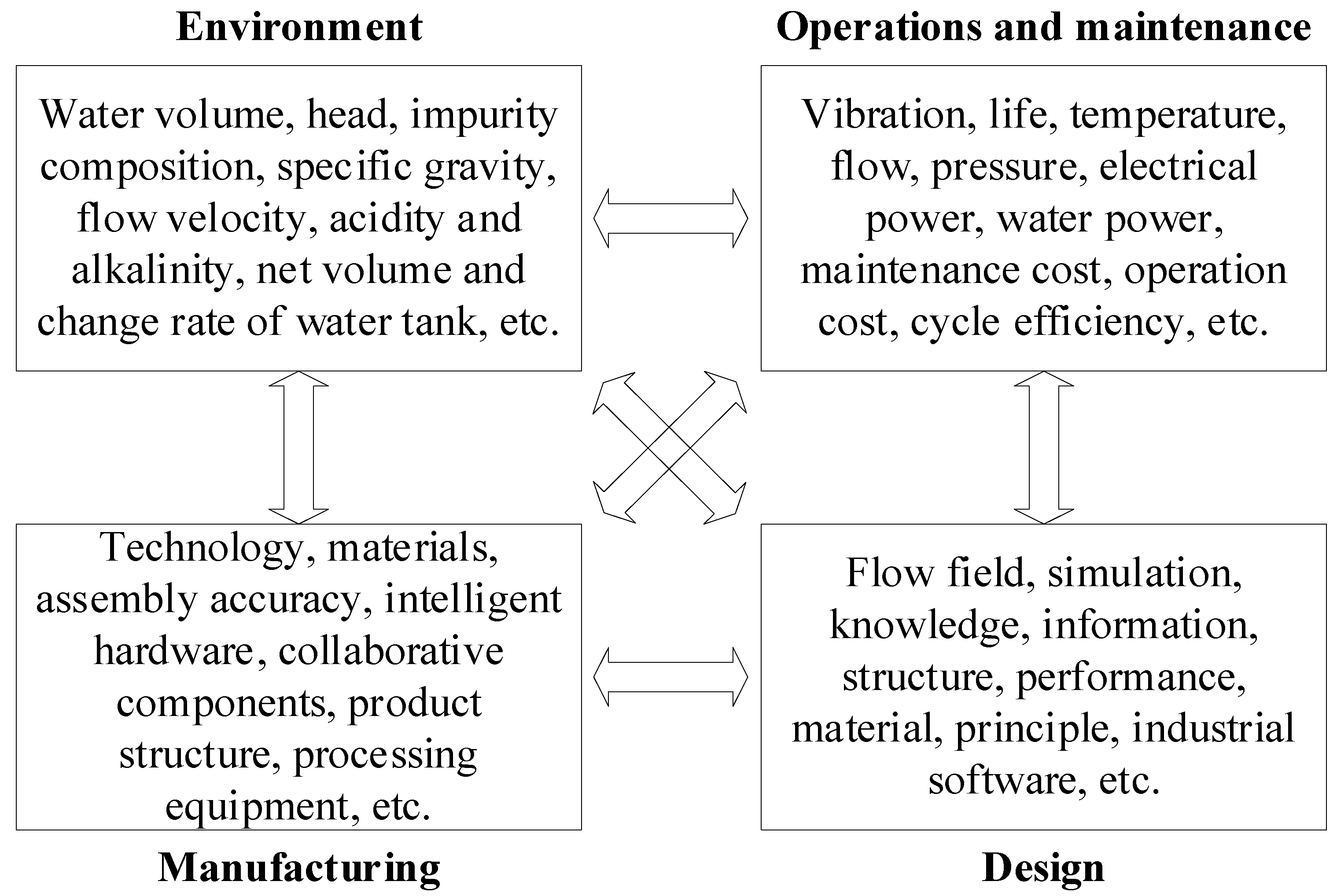
4. Key Technologies for and Core Characteristics of DMS-DT

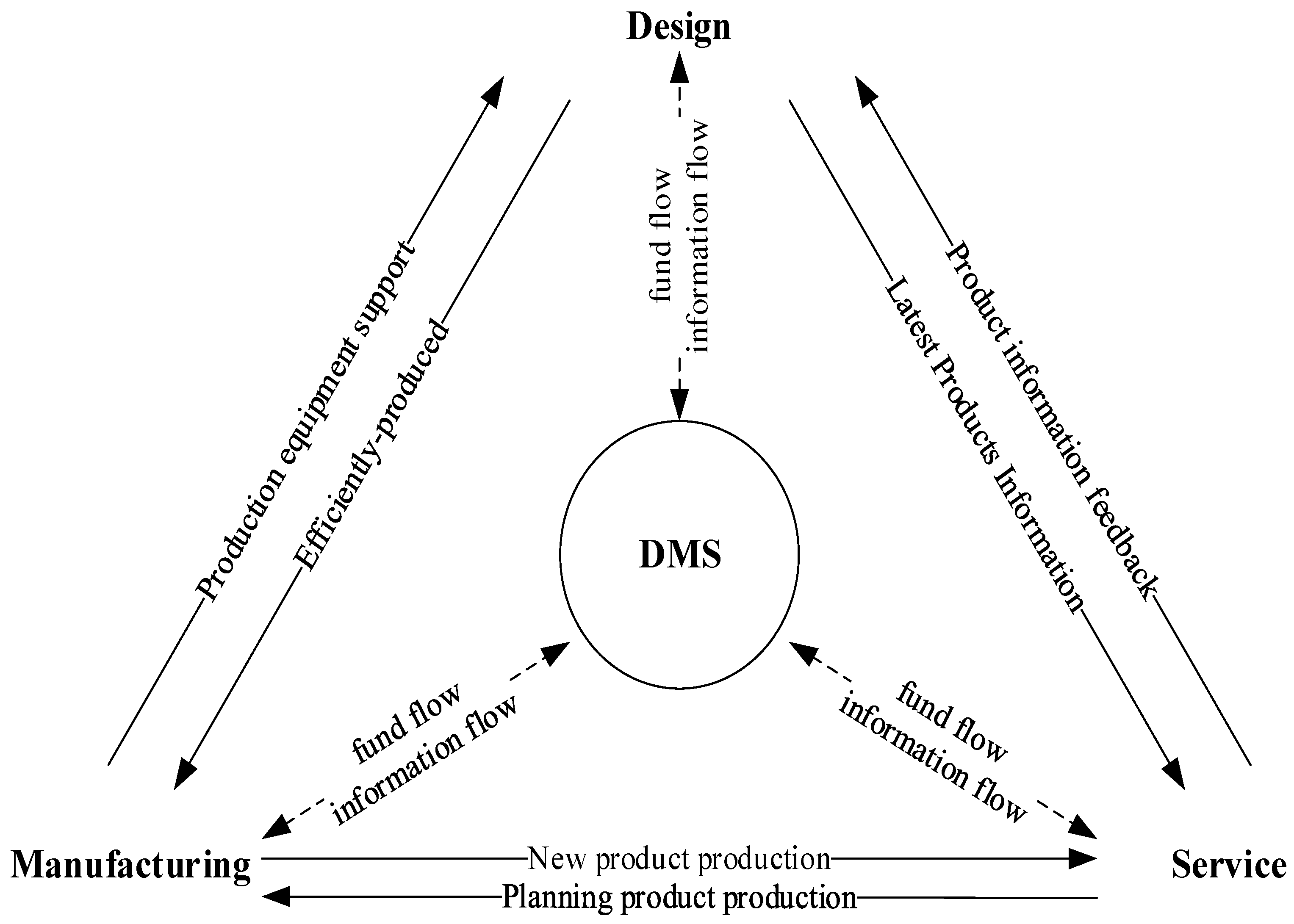
4.1. Integration of DMS

The integration of DMS can help enterprises to optimize the lifecycle through the technological innovation of the R&D department, the component manufacturing and assembly of the manufacturing department, and the service of downstream departments to undertake engineering projects based on products. As shown in Figure 3, the DMS integration mode aims at added value; integrates decentralized R&D, manufacturing, product, and service resources; and creates a virtuous cycle of demand-driven innovation and technology-driven innovation through cooperation with enterprises upstream and downstream of the industrial chain. It is a beneficial exploration of the innovation operation paradigm in the context of IM. R&D and design in DMS explore the potential needs of users, creatively making use of scientific and technological knowledge (such as literature, patents, technology, etc.) to innovate and improve products in terms of function and structure. Manufacturing is the basis of enterprise R&D and manufacturing. Through the processing and utilization of manufacturing resources such as materials, energy, technology, and information, new products can be produced, or existing products can be innovatively improved. The service process refers to the marketing department of the enterprise through advertising, brand, packaging, sales, and after-sales links, to provide products and services to users.

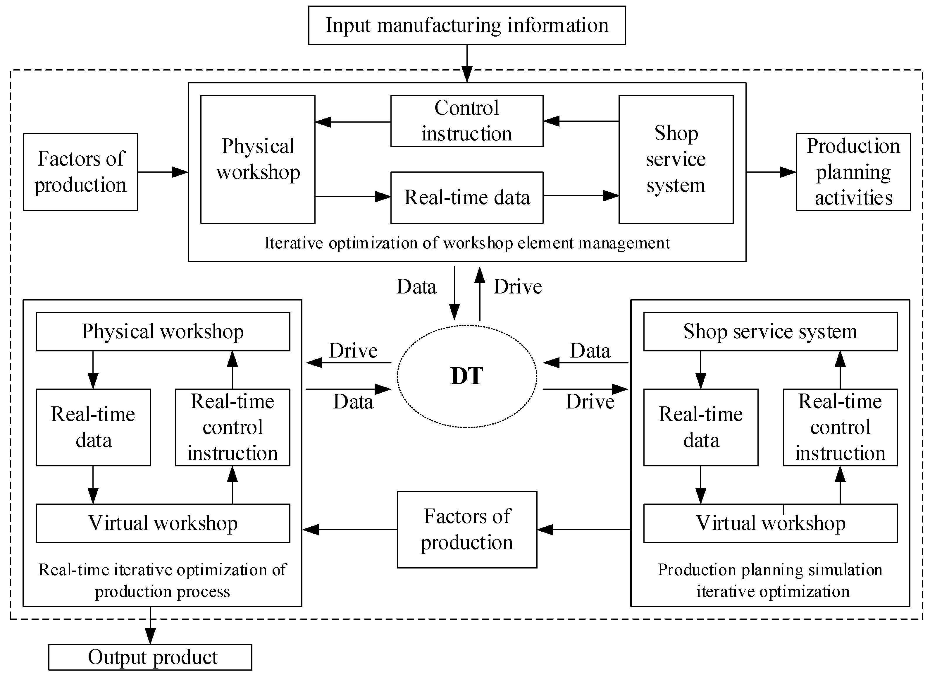
4.2. Implementation Mechanism Based on DMS-DT

The integrated framework of DMS-DT can be resolved as an integrated closed loop of DMS and DT, as shown in Figure 4. The integrated closed loop of DMS covers the three stages of design, manufacturing, and service, including user demand, scheme design, technical design, virtual prototype, manufacturing process, production process, service, etc. It includes function-oriented design, demand-oriented design, manufacturing-oriented design, and service-oriented design. The closed loop of DT includes demand DT, design DT, workshop total factor DT, service DT, and other information data carriers. In the integrated framework of DMS-DT, the integrated closed loop of DMS is a physical loop, which is equivalent to PE. The closed loop of DT is the virtual loop, which is equivalent to the VE. They form the PE-VE interaction iterative optimization in DMS.

4.3. Product Design Method Based on DMS-DT

The influence of DMS-DT on the product design stage is mainly reflected in the following three aspects.

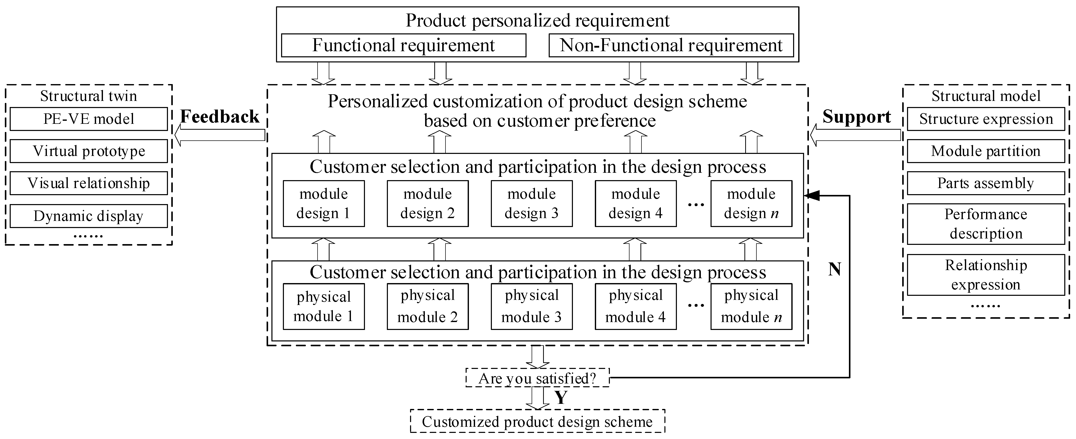
4.3.1. Identification of Design Requirements Based on DMS-DT

Rapid identification, function mapping, and market prediction of IM requirements are realized based on DMS-DT, thus providing decision support for the design, as shown in Figure 5. The demand identification and mapping based on DMS-DT can create personalized, realtime interaction. It can predict demand satisfaction of product behaviors in DMS so that engineers can master possible changes in users and demand in advance. Rapid virtual health analysis and PLC deductions are then performed to avoid the delays and cost increases associated with unpredictable design changes. Finally, DMS-DT is used to integrate the data and realize the combination and superposition in the VE to solve potential conflicts between requirements in the design.
For demand analysis and forecast based on DMS-DT, all the parameters in the PE will have a corresponding digital mapping in VE. The manufacturing, operation, and service of products also realize digital transformation. Each usage behavior trajectory is accurately mapped through DT to form the data information set of “product manufacturing” and “product service”. Then, through data analysis and information mining, we can acquire information on product usage preferences, environment, life, complete operation parameters, and even service defects. Based on the behavior characteristics of products, a simulation analysis with high confidence is carried out in VE to predict the product preference migration rules, deduce the future product usage scenarios, and evaluate the impact of new product functions. In conclusion, the user-oriented personalized demand mining and customized service in intelligent manufacturing can be realized.

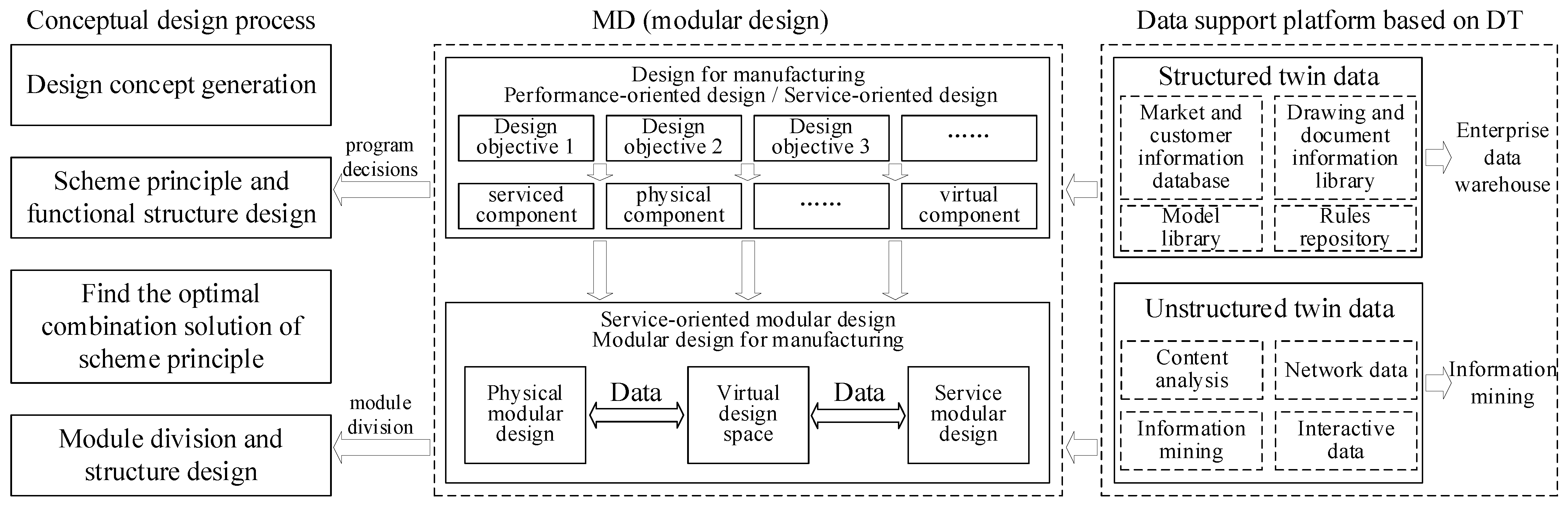
4.3.2. Product Conceptual Design Based on DMS-DT

Product conceptual design can be summarized as design intention generation, scheme principle functional structure design, searching for the optimal combination of original understanding, module division, and structural design. However, in traditional design, designers pay more attention to qualitative analysis and ignore the collection and application of real product data, which limits the efficiency of problem solving. Product conceptual design based on DMS-DT can make up for this deficiency. DT, as a realtime simulation of the whole element of the PE in the VE, runs through the whole lifecycle of the product PLC and provides a feasible way for designers to realize the technology. The conceptual design based on DMS-DT is shown in Figure 6. In traditional design, the decision is made based on a modular design, and the design, manufacturing, and service are independent of each other. The conceptual design driven by DMS-DT is based on a DT data platform to manage structured DT data and unstructured DT data so that design data can run through DMS. Not only are customers fully involved in product planning, but manufacturers can also interact with designers virtually, which surpasses geographical and spatial barriers and improves efficiency with longer time and depth.
Based on DMS-DT conceptual design, the real user data, product manufacturing parameters, service function data, and historical design data of DT can provide abasis for designers to determine the product system level and improve problem solving in design concept generation. In addition, DMS-DT-based design supports scheme decisions and module divisions of conceptual design, manufacturing-oriented design, and service-oriented design. Manufacturing-oriented design, by finding service components and physical components to meet different design goals, and combining these component requirements, can achieve the highest user satisfaction, while maximizing the manufacturer’s profit. Service-oriented design is mainly used to find the lowest-cost products and services in the configuration design system according to the optimal demand scheme. It is composed of as many physical modules and service modules that can meet the needs of specific market segments as possible.

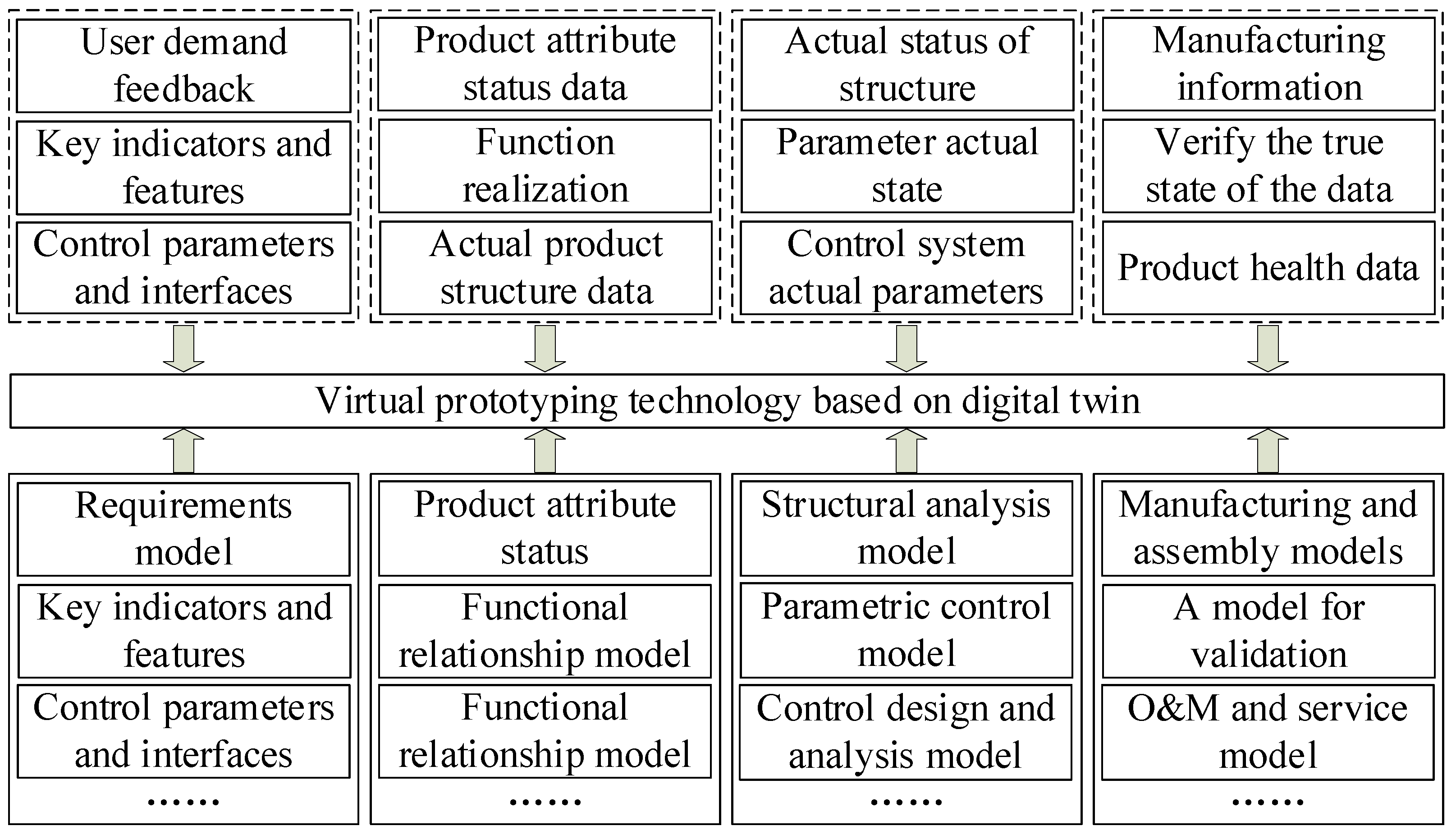
4.3.3. Virtual Prototype Based on DMS-DT

A virtual prototype is a digital model that can reflect the authenticity of a physical prototype. Engineers can describe the structure, shape, physical parameters, material composition, and basic functions through a virtual prototype, and define the product digitally before the actual production of a physical product. Based on the integration of technical data and management capabilities, a virtual prototype based on DMS-DT can map the actual processing, assembly, operation, maintenance, and other real states of products in the PE in realtime, thus providing a virtual platform for DMS. To realize the above functions, based on DT, a virtual prototype not only needs to realize the digital replication of design objects in the VE but also must establish an information model of product design, process analysis, processing, assembly, inspection, and so on. More important is the feedback that can describe the PE of product manufacturing, operation, maintenance, and so on. For example, in the processing process, these would be the real processing sequence, the resources consumed by different processes, the fixtures used, the time required, etc.
Figure 7 shows the technical framework required to implement virtual prototyping based on DMS-DT. DMS-DT enables virtual prototype technology to form a complete closed loop. Through the virtual prototype based on DMS-DT, we improved the design and subsequent fabrication, inspection, operation, and maintenance. The VE can obtain high realtime data from PE, through high-fidelity modeling simulation and analysis, and can, in turn, monitor, diagnose, and predict the possible state of the PE product. Finally, the integration of information physics is realized.

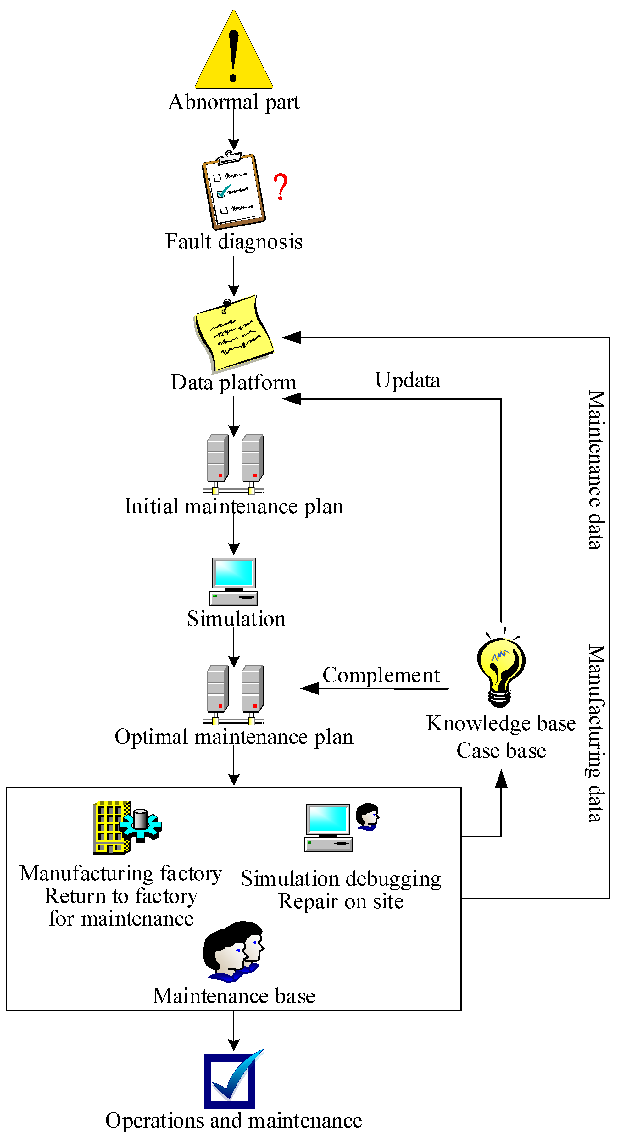
4.4. Product Service Method Based on DMS-DT

The deep integration of product DMS requires making full use of resources, data, platform, and information, and is an important basis for the realization of DMS-DT. If an exception occurs during service, the fault information can be sent to the manufacturer promptly. During the manufacturing stage, the workshop service platform optimizes the virtual working and physical running state according to the production planning, maintenance, and verification adjusted during the simulation. The implementation route of service based on DMS-DT is shown in Figure 8.
The information center receives service data and synchronizes the data with designers and manufacturers. According to the requirements of service, designers design, and update products from the design end, and accurately carry out timely product update plans based on service. The manufacturer develops appropriate manufacturing service plans according to the different floor plans, assembly station distribution, and staffing of the manufacturing plant. If the manufacturer receives service requirements, it checks the manufacturer’s corresponding spare parts to meet the requirements of the operation site or service manufacturer. If the inventory meets the spare parts requirements, it checks the manufacturer’s corresponding spare parts. If the stock meets the requirement of spare parts, it can be arranged. Otherwise, the task is transformed into an emergency order, and call plans and call models produce unplanned and scheduled plans. Then, the DMS scheduling scheme is simulated and optimized for the realtime data of the VE information center equipment and material resources. After repeated demand feedback and simulation optimization, design optimization and manufacturing efficiency improvement based on service data are realized.

5. Application Case

The self-balancing multistage pump has the characteristics of multiple collaborative departments, and high integration and complex process. It conforms to the definition of complex products in manufacturing industry. In this paper, an enterprise has MD500-90×7 self-balancing multistage pump. According to the market demand, it is necessary to carry out product upgrades. DMS-DT framework is adopted in this process. In cooperation with enterprises, we have developed a kind of drainage device for ultra-high lift and large flow, MD650-80×12P. In the process of R&D and production of MD650-80×12P, we can verify the scientific practicality of DMS-DT framework. Moreover, it is worth paying attention to whether the PLC of MD650-80×12P self-balancing multistage pump based on DMS-DT compared with MD500-90×7 is effectively optimized. What is the industrial performance of the MD650-80×12P self-balancing multistage pump? Through the verification of these problems, it can prove the feasibility and scientific nature of product development and upgrade based on DMS-DT.

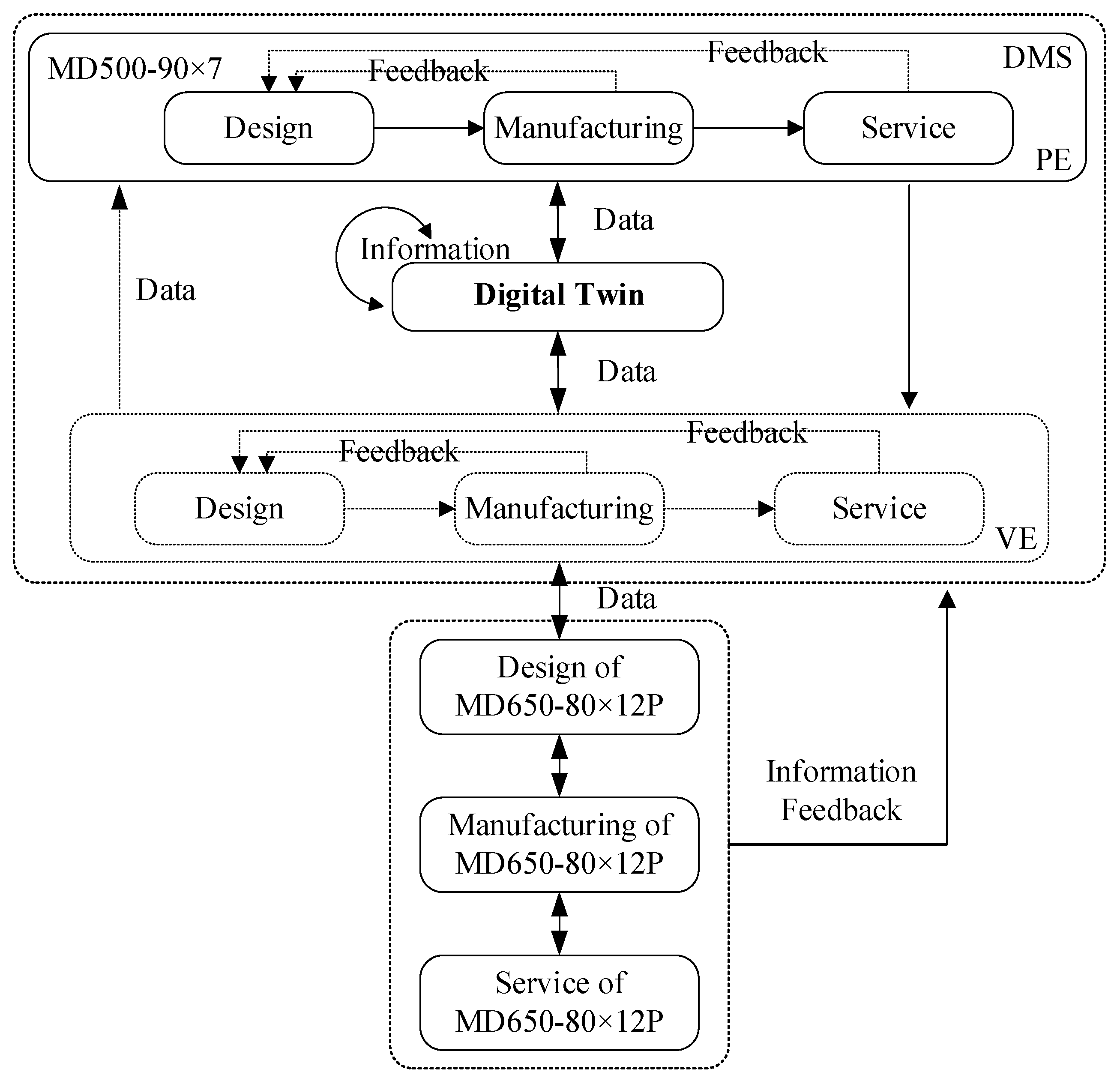
5.1. Development of Self-Balancing Multistage Pump Based on DMS-DT

As a typical representative of large centrifugal pump manufacturers in China, Henan Zheng Pump Technology, its products widely serve coal mines, electric power, and other industries. DMS-DT is an integrated application system of DMS and DT. Through the construction and verification of DMS-DT, the theoretical method is transformed into practical application. Take the MD500-90×7 and MD650-80×12P self-balancing multistage pump as an example to develop and upgrade the product within the manufacturer.

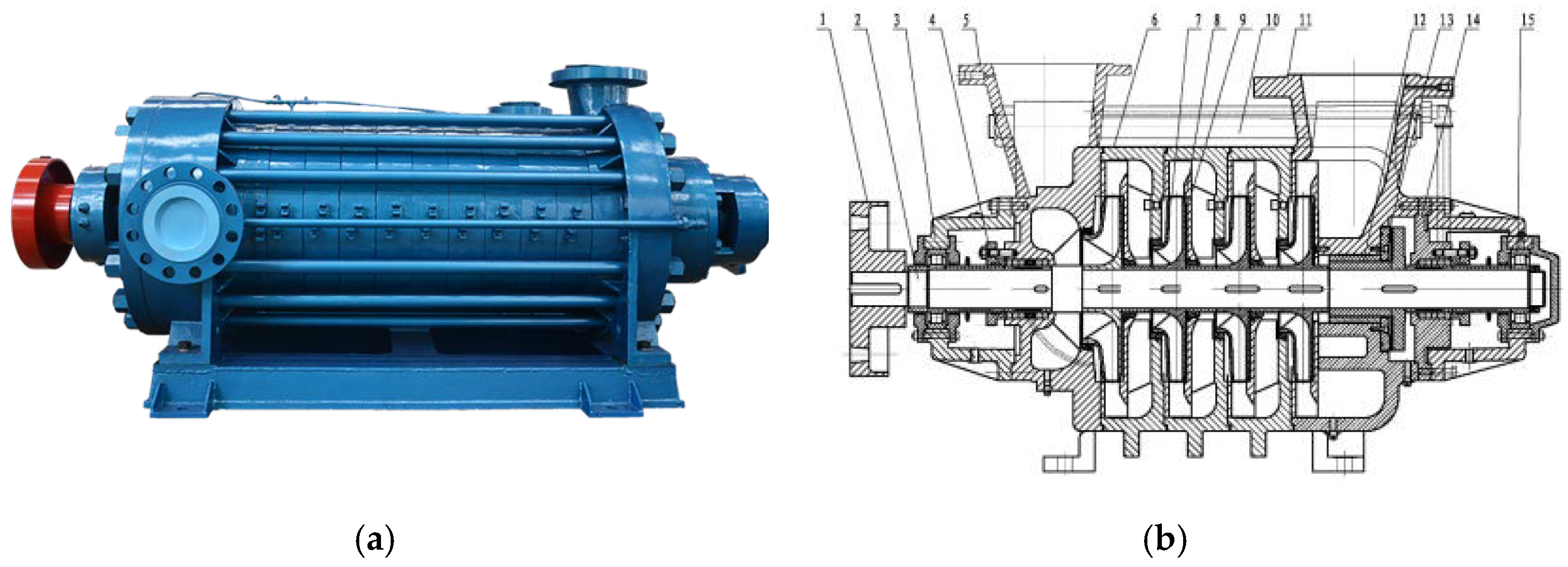
5.1.1. Parameter Analysis of MD500-90×7

In terms of structure, MD500-90×7 is mostly a segment-type multistage pump with an impeller in the same direction, as shown in Figure 9. The multistage pump is composed of two or more two centrifugal pump flow components through the series to achieve fluid transport. On the flow channel structure, the medium pressure relief port of the first stage flow component is communicated with the inlet of the second stage flow component, and the medium pressure relief port of the second stage flow component is communicated with the inlet of the third stage flow component. The main components are the suction section, impeller, radial guide vane, middle section, pressure water section, etc. The suction section is located in front of the inlet of the first stage impeller, and the fluid is sucked into the impeller from the inlet pipe, and then the radial guide vane collects the fluid flowing out of the impeller and delivers it to the inlet of the next stage impeller, to convert the fluid velocity energy into pressure energy, and the fluid is discharged along the pressure water section after the last stage of the multistage pump guide vane. The MD500-90×7 self-balancing multistage pump is composed of four systems, a stator system, rotor system, bearing system, and shaft seal system, as shown in Figure 9.
Table 1 shows the main technical parameters of the MD500-90×7 self-balancing multistage pump.

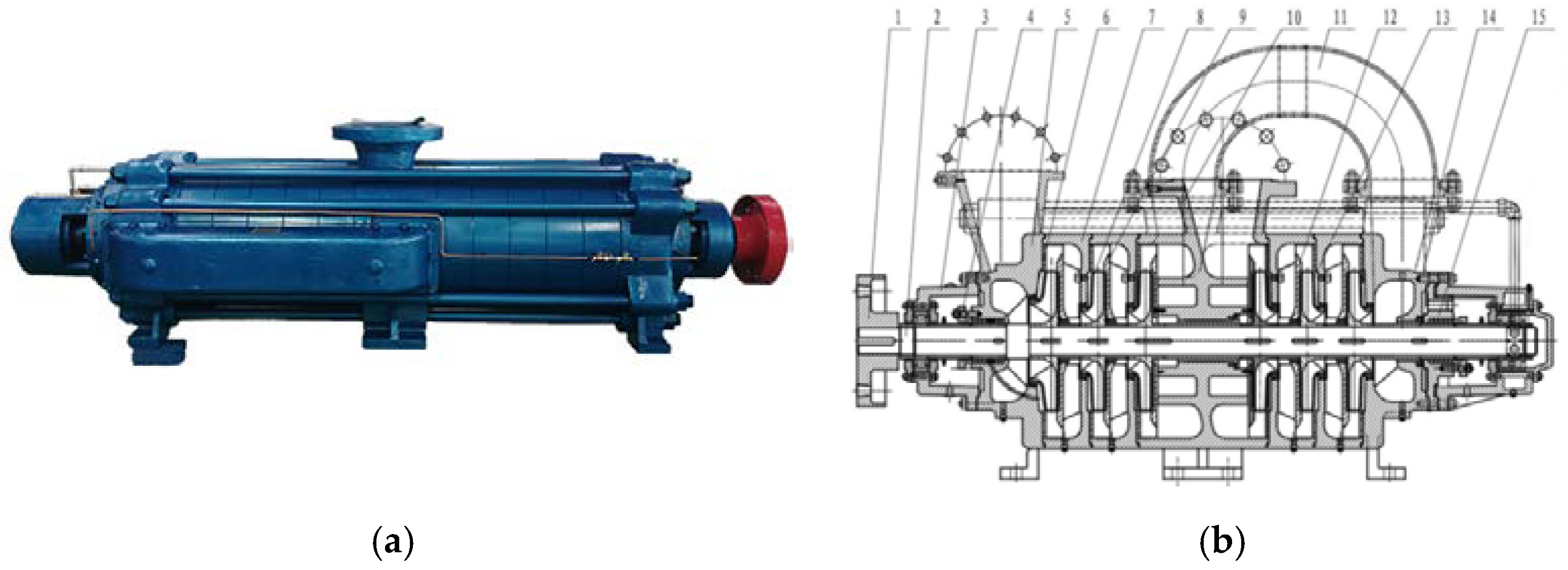
5.1.2. Development of MD650-80×12P Based on DMS-DT

According to the application framework in Figure 1 proposed in Section 3, we review the application framework of DMS-DT self-balancing multistage pump development. From design to manufacturing and formal operations, the whole physical process related to DMS is based on the DMS-DT framework. The information center is the transfer center of design parameters, manufacturing parameters, and service parameters to realize the mapping and interaction between synchronized data and models.
By establishing a DT platform based on DMS, we integrated the self-balancing multistage pump-related software and tools such as design, manufacturing, simulation, testing, data processing, dynamic demonstration, failure prediction, control, and scheduling management. Thus, the construction of a DMS-DT application scenario of MD650-80×12P self-balancing multistage pump was realized MD650-80×12P.
The build detail diagram is shown in Figure 1. Figure 10 based on Figure 1 shows the process of R&D based on DMS-DT from MD500-90×7 to MD650-80×12P.
In this paper, DMS-DT is built for the intelligent R&D and manufacturing of MD650-80×12P self-balancing multistage pump. During the DMS of MD500-90×7, the service data of the product can be fully fed back to the design and manufacturing stage. In the design stage, the operating status data of the product can be fully understood for the update and optimization of MD650-80×12P. The data is transmitted to VE synchronically through DT, and the flow data of DMS of MD500-90×7 is constructed. Based on this, the product MD650-80×12P was upgraded by a virtual prototype. Thus, the PLC of MD650-80×12P is shortened from the design. In addition, the manufacturing and service information about MD500-90×7 can also be synchronized to the entire development process of MD650-80×12P to promote and accelerate the realization of the product. Since driven by DT, a self-balancing multistage pump can completely break through the design, manufacturing, and service, meeting the feasibility and consistency requirements of DMS-DT.

5.1.3. Parameter Analysis of MD650-80×12P

Structurally, the self-balancing multistage pump adopts a segmented multistage pump with an asymmetrical impeller arrangement, as shown in Figure 11. It is under the drive of motor rotation, the liquid work, which allows it to increase energy, the volume in the liquid pool is increased by transferring it through the inlet section of the pump, the impeller, guide vane, transition pipe, secondary water section, and impeller, and it flows out via the vertical outlet.
The self-balancing multistage pump is composed of four systems, a stator system, rotor system, bearing system, and shaft seal system, as shown in Figure 10:
  • Stator system: mainly consists of an inlet section, middle section, outlet section, secondary inlet section, positive guide vane, anti-guide vane, decompression device, transition pipe, and other parts. The suction inlet is horizontal and the outlet is vertical.
  • Rotor system: it mainly consists of a shaft, impeller, anti-impeller, throttling and decompression device, and shaft sleeve. The shaft transfers power to the impeller to make it work. The driving end uses a cylindrical roller bearing, while the end uses an angular contact ball bearing. The replaceable bushing is installed at both ends of the shaft to protect it.
  • Bearing system: mainly rolling bearings, bearings using a “solid-traveling” dry oil lubrication structure, and a driving end using cylindrical roller bearings or angular contact ball bearings.
  • Shaft seal system: packing seal or mechanical seal, mainly by the water inlet section and tail cover of the sealing function, and water ring. Seal the liquid in the working room to play the role of water sealing, water cooling, and lubrication, among which the sealing water comes from the pressure water in the pump.
Table 2 shows the main technical parameters of the MD650-80×12P self-balancing multistage pump.

5.2. Product Life Cycle Efficiency Statistics

In this paper, an integrated framework based on DMS-DT covering all elements of design, manufacturing, and service is developed. The design parameters, manufacturing parameters, and operating parameters (equipment state parameters, working object parameters, and environmental parameters) of the pump are collected by DMS-DT. Related parameters are also shown in Figure 12, as follows.
Design parameters: hydraulic model selection (water wheel, guide vane), design efficiency, vibration calculation, strength calculation, purchased parts brand and specification, etc.
Manufacturing parameters: material details, process, processing tools, assembly tolerance, quality data, outsourcing manufacturers and specifications, etc.
Operation parameters: pump flow, inlet and outlet pressure, vibration, noise, start and stop time, vibration time function, efficiency time function; Voltage, current, power factor, and useful power of the motor; Water level change, water quality change, slime content, etc.
The above parameters are cardinality data, and the integrated relationship among design, manufacturing, and service data is opened through DMS. Data interconnection is realized through DT. Thus, DMS-DT can achieve comprehensive improvement in design, manufacturing, and service, and reduce the cost of PLC by shortening the time.
In the R&D process of MD650-80×12P, the integration and circulation of DMS-DT have effectively improved the R&D and production efficiency of water pumps and reduced maintenance costs. In terms of design and manufacturing, the time efficiency is effectively improved by 20% compared with MD500-90×7. Supported by data on design and manufacturing, maintenance costs and expenses were reduced by 22% compared with MD500-90×7, and operational service efficiency was significantly improved. The above data comes from the actual monitoring statistics of the workshop.

5.3. Industrial Performance Verification of MD650-80×12P

This chapter focuses on testing the industrial performance of the MD650-80×12P self-balancing multistage pump. The objective of the industrial operation test, technical parameters of the industrial test, basis, and method of the industrial operation test, and analysis of test results are established. Finally, the conclusions about the industrial test operation of the MD650-80×12P self-balancing multistage pump are given.

5.3.1. Industrial Test Objectives

The performance of the MD650-80×12P self-balancing multistage pump developed and manufactured based on DMS-DT was as follows:
  • The water pump was an excellent hydraulic model, and the flow passage of the shell flow parts was refined to ensure smooth flow and small hydraulic losses. Compared with the efficiency of the traditional hydraulic model, the efficiency of the whole machine increased by 2 percentage points.
  • High efficiency and high reliability were achieved through the impeller and guide vane of the best collocation, as well as a reasonable gap with a wide axial throttling design so that the pump can still maintain a high degree of stability and high efficiency after long-term operation.
  • Under the condition of sewage with 0.1–1% solid particle content, there is no overhaul for 5000 h, and the efficiency decrease is less than 5%. Under the condition of sewage with a solid particle content of 1–1.5%, there is no overhaul for 3000 h, and the efficiency decrease is less than 6%.
  • When in the range of 0.7–1.3 times flow, the pump shaft power should not exceed the rated power of the electric pump.
  • The performance parameters of the pump meet the above technical requirements. The efficiency meets the requirements of GB/T 13007-2011 [60]. The vibration intensity of the pump should conform to the provisions of grade C in GB/T 29531-2013 [61]. The noise of the pump shall comply with the provisions of grade C in GB/T 29529-2013 [62].

5.3.2. Drainage System Layout and Technical Parameters

Since each mine drainage system is different, but drainage systems are built on similar and universal principles, we can take the mine drainage system of Shaanxi Zheng Tong Coal as an example to introduce the general layout and design of mine drainage systems. According to the special hydrological environment and drainage demand characteristics of the mine, the project plans to adopt the MD650-80(P) self-balancing multistage pump as the main drainage equipment. Figure 13 shows several self-balancing multistage pump control platforms in the mine drainage system.

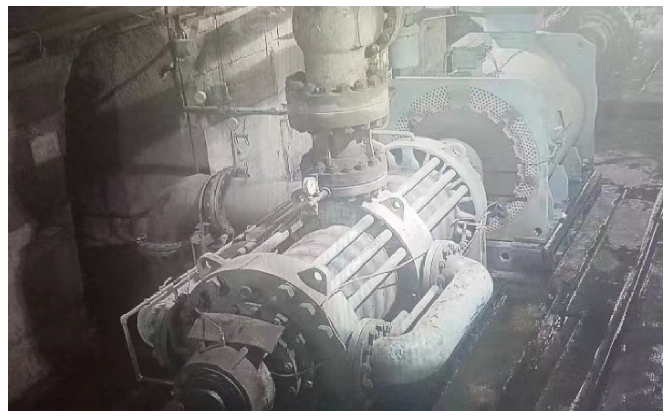
5.3.3. Industrial Operation Tests and Results Analysis

According to the industrial test objectives, corresponding inspection items are formulated for multistage pumps, and the specific inspection results of the corresponding items are shown in Table 3. The flow rate, outlet pressure, inlet pressure, vibration displacement, current, voltage, and bearing temperature of the equipment are monitored by an ultrasonic flow meter, precision pressure gage, vacuum meter, vibration acceleration sensor, ammeter, voltmeter, and temperature sensor, respectively.
The MD650-80×12P self-balancing multistage pump was tested by the Coal Industry Energy Saving and Safety Monitoring Center of Henan Coal Academy of Sciences, and the specific test results are shown in Table 4.

5.3.4. Hydraulic Performance Test and Result Analysis of Self-Balancing Multistage Pump

In addition to the above industrial operation tests, hydraulic performance tests were carried out on multistage pumps and self-balancing multistage pumps in this project. The hydraulic performance tests were carried out at the Open Turbo machinery Facility (OTF) of Henan Zheng Pump. The test bench is a water pump testing platform by the GB/T 3216-2016 [64] national standard identified by the National Industrial Pump Quality Supervision and Inspection Center. Table 5 shows the hydraulic performance data of the MD650-80×12P self-balancing multistage pump.
According to the data in Table 4, the relationship curves between head H, shaft power P, efficiency η, and flow Q were calculated at a certain speed n. According to the hydraulic performance test results of the MD650-80×12P self-balancing multistage pump, the operational efficiency of this type of multistage pump is 82.5%, higher than the qualified standard, and the efficiency is improved compared with the efficiency of the traditional hydraulic model.

5.3.5. Analysis of Industrial Operation Results

According to the above technical performance indicators of a multistage pump and a self-balancing multistage pump, the industrial operation results of MD650-80×12P self-balancing multistage pump are as follows:
  • The MD650-80×12P self-balancing multistage pump is a high-efficiency hydraulic model, and the rapid molding and precision casting technology effectively ensures smooth hydraulic flow, reduces hydraulic loss, and improves the efficiency of the whole machine.
  • Under the conditions of clean water and continuous operation for 6000 h without overhaul, the efficiency drop is not more than 4%. Under the condition of sewage with 0.1–1.5% solid particle content, the efficiency decreases by less than 6% after continuous operation for 4000 h without overhaul.
  • When in the range of 0.7–1.3 times flow, the shaft power of the pump should not exceed the rated power of the electric pump.
  • The performance parameters of the machine meet the above technical requirements, and the efficiency is higher than GB/T 13007-2011 [60]. The vibration intensity of the pump should conform to the provisions of grade C in GB/T 29531-2013 [61]. The noise of pump shall comply with the provisions of grade C in GB/T 29529-2013 [62].

6. Conclusions

By integrating the connotations and goals of DMS and DT, we found that DT is the core implementation technology of IM and DMS is the effective carrier. The main contributions of this paper are as follows. (a) An integration framework based on DMS-DT was proposed, and corresponding key technologies were discussed. (b) The implementation process of DMS integration optimization was discussed from the perspective of PLC. Based on DT, the cross-domain circulation of PLC data was realized. (c) The rationality of the DMS-DT framework was verified by taking the development and manufacture of a self-balancing multistage pump as an example. The product performance of the MD650-80×12P self-balancing multistage pump was tested, and the product development of DMS-DT was verified.
In the process of research, there are some shortcomings in the research while expanding the analysis of the problem. Details are as follows:
  • DT as an emerging technology has not been fully implemented, especially in small and medium-sized enterprises. The first half of this paper focuses on the construction of the DMS-DT theoretical framework. Comparatively speaking, the framework is built based on the assumption of DT landing application. However, in practical application, the technical level of the DMS-DT integration framework cannot fully support the theoretical level.
  • Along with problem 1, problem 2 is manifested in the proof process of actual cases. Due to the limitation of DT technology application, data collection and collation in cases are incomplete. Meanwhile, it can be understood that the efficiency can be improved under the condition that DT technology has not played a full role. It can be predicted that the future potential of DT in the field of manufacturing needs to be further explored.
  • The comparison of parameters in this study can compare the efficiency improvement of products. However, the improvement of production efficiency and the overall lifecycle is not limited to the comparison of using parameters, and the comparison itself is a topic worthy of research.
The framework structure, implementation mechanism, operation flow, and interaction mechanism of DMS-DT were discussed. We have researched the integration problem of PLC. With the promotion of DT technology, the prospect of integration optimization will be further expanded. Future work will concentrate on the following aspects:
  • The DMS-DT framework itself is integration research. Integration itself involves the efficiency of problem, the integration framework is the same. The integration of the DMS framework and the calculation of its integration efficiency is a problem worthy of continuous attention. How to optimize the integration mode, integration effect and integration approach of design manufacturing and service at the grass-roots level. Future research is worthy of further expansion.
  • The mechanism design of the integration framework is also worth paying attention to in the future. The integration of PLC in many fields will inevitably lead to multiparticipant problem products and naturally lead to multiparticipant balanced game problems. The information mechanism between multi-participant subjects, the division mechanism of the degree of participation of the main body, and the information disclosure mechanism between various stages are all worthy of an in-depth discussion in the future.
  • With the integration of DT technology and DMS, virtual space will play more roles in PLC in the future. Therefore, virtual prototyping technology, virtual modeling, and simulation technology will be key topics in the future research field.
In addition, the data construction and management in DMS-DT, modeling problems in ultra-high fidelity in DMS-DT, the simulation of DMS-DT, and more applications will also be topics worth discussing in the future.

Author Contributions

Conceptualization, L.F. and L.Z.; methodology, L.Z.; software, L.F.; validation, L.F. and J.W.; formal analysis, K.-Y.L.; investigation, L.Z.; resources, K.-Y.L.; data curation, L.F.; writing—original draft preparation, L.Z.; writing—review and editing, K.-Y.L.; visualization, J.W.; supervision, J.W.; project administration, J.W. and K.-Y.L. All authors have read and agreed to the published version of the manuscript.

Funding

This research was funded by the Innovation Method Fund of China, grant number 2018IM020300; the Innovation Method Fund of China, grant number 2019IM020200; the Joint Funds of National Natural Science Foundation of China, grant number U1904210-4; and the Shanghai Science and Technology Program, grant number 20040501300.

Data Availability Statement

Not applicable.

Conflicts of Interest

The authors declare no conflict of interest.

References

  1. Liu, M.; Fang, S.; Dong, H.; Xu, C. Review of digital twin about concepts, technologies, and industrial applications. J. Manuf. Syst. 2020, 58, 346–361. [Google Scholar] [CrossRef]
  2. Semenkov, K.; Promyslov, V.; Poletykin, A.; Mengazetdinov, N. Validation of Complex Control Systems with Heterogeneous Digital Models in Industry 4.0 Framework. Machines 2021, 9, 62. [Google Scholar] [CrossRef]
  3. Wang, Y.; Ren, W.; Li, Y.; Zhang, C. Complex product manufacturing and operation and maintenance integration based on digital twin. Int. J. Adv. Manuf. Technol. 2021, 117, 361–381. [Google Scholar] [CrossRef]
  4. Huang, S.; Wang, G.; Lei, D.; Yan, Y. Toward digital validation for rapid product development based on digital twin: A framework. Int. J. Adv. Manuf. Technol. 2022, 119, 2509–2523. [Google Scholar] [CrossRef]
  5. He, B.; Bai, K.-J. Digital twin-based sustainable intelligent manufacturing: A review. Adv. Manuf. 2020, 9, 1–21. [Google Scholar] [CrossRef]
  6. Zheng, M.; Tian, L. A Hierarchical Integrated Modeling Method for the Digital Twin of Mechanical Products. Machines 2021, 10, 2. [Google Scholar] [CrossRef]
  7. Kumar, S.; Manjrekar, V.; Singh, V.; Kumar Lad, B. Integrated yet distributed operations planning approach: A next genera-tion manufacturing planning system. J. Manuf. Syst. 2020, 54, 103–122. [Google Scholar] [CrossRef]
  8. Hedberg, T.D.; Sharp, M.E.; Maw, T.M.M.; Helu, M.M.; Rahman, M.M.; Jadhav, S.; Whicker, J.J.; Feeney, A.B. Defining requirements for integrating information between design, manufacturing, and inspection. Int. J. Prod. Res. 2021, 1–21. [Google Scholar] [CrossRef]
  9. Xie, Y.; Lian, K.; Liu, Q.; Zhang, C.; Liu, H. Digital twin for cutting tool: Modeling, application and service strategy. J. Manuf. Syst. 2020, 58, 305–312. [Google Scholar] [CrossRef]
  10. Siiskonen, M.; Malmqvist, J.; Folestad, S. Integrated product and manufacturing system platforms supporting the design of personalized medicines. J. Manuf. Syst. 2020, 56, 281–295. [Google Scholar] [CrossRef]
  11. Zhou, Y.; Song, Y.; Xing, T.; Wang, Y.; Zhang, Q.; Shao, L.; Du, F.; Ding, S. Parametric modeling method for integrated design and manufacturing of radial compressor impeller. Int. J. Adv. Manuf. Technol. 2020, 112, 1007–1021. [Google Scholar] [CrossRef]
  12. Molinaro, R.; Singh, J.-S.; Catsoulis, S.; Narayanan, C.; Lakehal, D. Embedding data analytics and CFD into the digital twin concept. Comput. Fluids 2020, 214, 104759. [Google Scholar] [CrossRef]
  13. Song, I.-H.; Chung, S.-C. Synthesis of the digital mock-up system for heterogeneous CAD assembly. Comput. Ind. 2009, 60, 285–295. [Google Scholar] [CrossRef]
  14. McHugh, R.; Zhang, H. Virtual prototyping of mechatronics for 21st century engineering and technology. Int. J. Eng. Res. Innov. 2011, 3, 1–12. [Google Scholar]
  15. Grieves, M. Digital Twin: Manufacturing Excellence through Virtual Factory Replication. White Pap. 2015, 1, 1–7. [Google Scholar]
  16. Tao, F.; Qi, Q. Make more digital twins. Nature 2019, 573, 490–491. [Google Scholar] [CrossRef] [Green Version]
  17. Grieves, M.; Vickers, J. Digital Twin: Mitigating Unpredictable, Undesirable Emergent Behavior in Complex Systems. In Transdisciplinary Perspectives on Complex Systems; Franz-Josef, K., Shannon, F., Anabela, A., Eds.; Springer: Berlin/Heidelberg, Germany, 2017; pp. 85–113. [Google Scholar]
  18. Schneider, G.F.; Wicaksono, H.; Ovtcharova, J. Virtual engineering of cyber-physical automation systems: The case of con-trol logic. Adv. Eng. Inform. 2019, 39, 127–143. [Google Scholar] [CrossRef]
  19. Sun, X.; Liu, S.; Bao, J.; Li, J.; Liu, Z. A Performance Prediction Method for a High-Precision Servo Valve Supported by Digi-tal Twin Assembly-Commissioning. Machines 2021, 10, 11. [Google Scholar] [CrossRef]
  20. Fujii, T.Y.; Hayashi, V.T.; Arakaki, R.; Ruggiero, W.V.; Bulla Jr, R.; Hayashi, F.H.; Khalil, K.A. A Digital Twin Architecture Model Applied with MLOps Techniques to Improve Short-Term Energy Con-sumption Prediction. Machines 2021, 10, 23. [Google Scholar] [CrossRef]
  21. Lin, T.Y.; Jia, Z.; Yang, C.; Xiao, Y.; Lan, S.; Shi, G.; Zeng, B.; Li, H. Evolutionary digital twin: A new approach for intelligent industrial product development. Adv. Eng. Inform. 2021, 47, 101209. [Google Scholar] [CrossRef]
  22. Van DerHorn, E.; Mahadevan, S. Digital Twin: Generalization, characterization and implementation. Decis. Support. Syst. 2021, 145, 113524. [Google Scholar] [CrossRef]
  23. Tao, F.; Sui, F.; Liu, A.; Qi, Q.; Zhang, M.; Song, B.; Guo, Z.; Lu, S.C.-Y.; Nee, A.Y.C. Digital twin-driven product design framework. Int. J. Prod. Res. 2018, 57, 3935–3953. [Google Scholar] [CrossRef] [Green Version]
  24. Da Luz, L.M.; de Francisco, A.C.; Piekarski, C.M.; Salvador, R. Integrating life cycle assessment in the product development process: A methodological approach. J. Clean. Prod. 2018, 193, 28–42. [Google Scholar] [CrossRef]
  25. Myrodia, A.; Randrup, T.; Hvam, L. Configuration lifecycle management maturity model. Comput. Ind. 2019, 106, 30–47. [Google Scholar] [CrossRef]
  26. Bicocchi, N.; Cabri, G.; Mandreoli, F.; Mecella, M. Dynamic digital factories for agile supply chains: An architectural ap-proach. J. Ind. Inf. Integr. 2019, 15, 111–121. [Google Scholar] [CrossRef] [Green Version]
  27. Kong, L.; Wang, L.; Li, F.; Lv, X.; Li, J.; Ma, Y.; Chen, B.; Guo, J. Multi-layer integration framework for low carbon design based on design features. J. Manuf. Syst. 2021, 61, 223–238. [Google Scholar] [CrossRef]
  28. Uysal, M.P.; Mergen, A.E. Smart manufacturing in intelligent digital mesh: Integration of enterprise architecture and soft-ware product line engineering. J. Ind. Inf. Integr. 2021, 22, 100202. [Google Scholar] [CrossRef]
  29. Kleinekorte, J.; Fleitmann, L.; Bachmann, M.; Kätelhön, A.; Barbosa-Póvoa, A.; Von Der Assen, N.; Bardow, A. Life Cycle Assessment for the Design of Chemical Processes, Products, and Supply Chains. Annu. Rev. Chem. Biomol. Eng. 2020, 11, 203–233. [Google Scholar] [CrossRef] [Green Version]
  30. Mandolini, M.; Marconi, M.; Rossi, M.; Favi, C.; Germani, M. A standard data model for life cycle analysis of industrial products: A support for eco-design initiatives. Comput. Ind. 2019, 109, 31–44. [Google Scholar] [CrossRef]
  31. Li, K.; Liu, J.; Fu, H.; Zhao, N. An integrated system with multiple product lifecycles for remanufacturing (IS-MPLR): New opportunities and challenges. Int. J. Comput. Integr. Manuf. 2021, 34, 20–40. [Google Scholar] [CrossRef]
  32. Zhang, Z.; Zhu, Z.; Zhang, J.; Wang, J. Construction of Intelligent Integrated Model Framework for the Workshop Manu-facturing System Via Digital Twin. Int. J. Adv. Manuf. Technol. 2022, 118, 3119–3132. [Google Scholar] [CrossRef]
  33. Borangiu, T.; Oltean, E.; Răileanu, S.; Anton, F.; Anton, S.; Iacob, I. Embedded Digital Twin for ARTI-Type Control of Semi-Continuous Production Processes; Springer: Berlin/Heidelberg, Germany, 2020. [Google Scholar]
  34. Redelinghuys, A.J.H.; Basson, A.H.; Kruger, K. A six-layer architecture for the digital twin: A manufacturing case study implementation. J. Intell. Manuf. 2019, 31, 1383–1402. [Google Scholar] [CrossRef]
  35. Tao, F.; Liu, W.; Zhang, M.; Hu, T.L.; Qi, Q.L. Five-dimension digital twin model and its ten applications. Comput. Integr. Manuf. Syst. 2019, 25, 1–18. [Google Scholar]
  36. Qi, Q.; Tao, F.; Hu, T.; Anwer, N.; Liu, A.; Wei, Y.; Wang, L.; Nee, A. Enabling technologies and tools for digital twin. J. Manuf. Syst. 2021, 58, 3–21. [Google Scholar] [CrossRef]
  37. Liu, Q.; Leng, J.; Yan, D.; Zhang, D.; Wei, L.; Yu, A.; Zhao, R.; Zhang, H.; Chen, X. Digital twin-based designing of the configuration, motion, control, and optimization model of a flow-type smart manufacturing system. J. Manuf. Syst. 2020, 58, 52–64. [Google Scholar] [CrossRef]
  38. Lai, X.; Wang, S.; Guo, Z.; Zhang, C.; Sun, W.; Song, X. Designing a Shape–Performance Integrated Digital Twin Based on Multiple Models and Dynamic Data: A Boom Crane Example. J. Mech. Des. 2021, 143, 071703. [Google Scholar] [CrossRef]
  39. Gu, Y.; Zhang, S.; Qiu, L. Digital Twin Driven Requirement Conversion in Smart Customized Design. IEEE Access 2021, 9, 64414–64426. [Google Scholar] [CrossRef]
  40. Polini, W.; Corrado, A. Digital twin of composite assembly manufacturing process. Int. J. Prod. Res. 2020, 58, 5238–5252. [Google Scholar] [CrossRef]
  41. Damjanovic-Behrendt, V.; Behrendt, W. An open source approach to the design and implementation of Digital Twins for Smart Manufacturing. Int. J. Comput. Integr. Manuf. 2019, 32, 366–384. [Google Scholar] [CrossRef]
  42. Esmaeilian, B.; Behdad, S.; Wang, B. The evolution and future of manufacturing: A review. J. Manuf. Syst. 2016, 39, 79–100. [Google Scholar] [CrossRef]
  43. Lattanzi, L.; Raffaeli, R.; Peruzzini, M.; Pellicciari, M. Digital twin for smart manufacturing: A review of concepts towards a practical industrial implementation. Int. J. Comput. Integr. Manuf. 2021, 34, 567–597. [Google Scholar] [CrossRef]
  44. Wu, Q.; Mao, Y.; Chen, J.; Wang, C. Application Research of Digital Twin-Driven Ship Intelligent Manufacturing System: Pipe Machining Production Line. J. Mar. Sci. Eng. 2021, 9, 338. [Google Scholar] [CrossRef]
  45. Zhu, Z.; Xi, X.; Xu, X.; Cai, Y. Digital Twin-driven machining process for thin-walled part manufacturing. J. Manuf. Syst. 2021, 59, 453–466. [Google Scholar] [CrossRef]
  46. Fan, Y.; Yang, J.; Chen, J.; Hu, P.; Wang, X.; Xu, J.; Zhou, B. A digital-twin visualized architecture for Flexible Manufacturing System. J. Manuf. Syst. 2021, 60, 176–201. [Google Scholar] [CrossRef]
  47. Guo, H.; Chen, M.; Mohamed, K.; Qu, T.; Wang, S.; Li, J. A digital twin-based flexible cellular manufacturing for optimization of air conditioner line. J. Manuf. Syst. 2021, 58, 65–78. [Google Scholar] [CrossRef]
  48. Tao, F.; Zhang, M. Digital Twin Shop-Floor: A New Shop-Floor Paradigm Towards Smart Manufacturing. IEEE Access 2017, 5, 20418–20427. [Google Scholar] [CrossRef]
  49. Park, K.T.; Nam, Y.W.; Lee, H.S.; Im, S.J.; Noh, S.D.; Son, J.Y.; Kim, H. Design and implementation of a digital twin application for a connected micro smart factory. Int. J. Comput. Integr. Manuf. 2019, 32, 596–614. [Google Scholar] [CrossRef]
  50. Sun, X.; Bao, J.; Li, J.; Zhang, Y.; Liu, S.; Zhou, B. A digital twin-driven approach for the assembly-commissioning of high precision products. Robot. Comput. Manuf. 2020, 61, 101839. [Google Scholar] [CrossRef]
  51. Mykoniatis, K.; Harris, G.A. A digital twin emulator of a modular production system using a data-driven hybrid modeling and simulation approach. J. Intell. Manuf. 2021, 32, 1899–1911. [Google Scholar] [CrossRef]
  52. Aheleroff, S.; Xu, X.; Zhong, R.Y.; Lu, Y. Digital Twin as a Service (DTaaS) in Industry 4.0: An Architecture Reference Model. Adv. Eng. Inform. 2020, 47, 101225. [Google Scholar] [CrossRef]
  53. Glaessgen, E.; Stargel, D. The Digital Twin Paradigm for Future NASA and U.S. Air Force Vehicles. In Proceedings of the 53rd AIAA/ASME/ASCE/AHS/ASC Structures, Structural Dynamics and Materials Conference, Honolulu, HI, USA, 23–26 April 2012. [Google Scholar] [CrossRef] [Green Version]
  54. Liu, S.; Bao, J.; Lu, Y.; Li, J.; Lu, S.; Sun, X. Digital twin modeling method based on biomimicry for machining aerospace components. J. Manuf. Syst. 2021, 58, 180–195. [Google Scholar] [CrossRef]
  55. Tao, F.; Cheng, J.; Qi, Q.; Zhang, M.; Zhang, H.; Sui, F. Digital twin-driven product design, manufacturing and service with big data. Int. J. Adv. Manuf. Technol. 2017, 94, 3563–3576. [Google Scholar] [CrossRef]
  56. Wang, X.V.; Wang, L. Digital twin-based WEEE recycling, recovery and remanufacturing in the background of Industry 4. Int. J. Prod. Res. 2018, 57, 3892–3902. [Google Scholar] [CrossRef]
  57. Duan, J.-G.; Ma, T.-Y.; Zhang, Q.-L.; Liu, Z.; Qin, J.-Y. Design and application of digital twin system for the blade-rotor test rig. J. Intell. Manuf. 2021, 1–17. [Google Scholar] [CrossRef]
  58. Niu, X.; Qin, S. Integrating crowd-/service-sourcing into digital twin for advanced manufacturing service innovation. Adv. Eng. Inform. 2021, 50, 101422. [Google Scholar] [CrossRef]
  59. Zhang, J.; Deng, T.; Jiang, H.; Chen, H.; Qin, S.; Ding, G. Bi-level dynamic scheduling architecture based on service unit digital twin agents. J. Manuf. Syst. 2021, 60, 59–79. [Google Scholar] [CrossRef]
  60. GB/T 13007-2011; Centrifugal Pump-Efficiency. Administration of Quality Supervision, Inspection and Quarantine of People’s Republic of China: Beijing, China, 2011.
  61. GB/T 29531-2013; Methods of Measuring and Evaluating Vibration of Pumps. Administration of Quality Supervision, Inspection and Quarantine of People’s Republic of China: Beijing, China, 2013.
  62. GB/T 29529-2013; Methods of Measuring and Evaluating Noise of Pumps. Administration of Quality Supervision, Inspection and Quarantine of People’s Republic of China: Beijing, China, 2013.
  63. GB/T 13469-2021; Economical Operation for Centrifugal, Mixed Flow and Axial Flow Pump Systems. State Administration for Market Regulation, Standardization Administration of PRC: Beijing, China, 2021.
  64. GB/T 3216-2016; Rotodynamic Pumps–Hydraulic Performance Acceptance Tests—Grades 1, 2 and 3. State Administration for Market Regulation, Standardization Administration of PRC: Beijing, China, 2016.
Figure 1. DMS-DT integration framework.
Machines 10 00275 g001
Figure 2. The operational mechanism of DT shop-floor [48].
Machines 10 00275 g002
Figure 3. Design–Manufacturing–Service integration framework.
Machines 10 00275 g003
Figure 4. The decomposition form of the DMS-DT integration framework.
Machines 10 00275 g004
Figure 5. Identification of design requirements based on DMS-DT.
Machines 10 00275 g005
Figure 6. Product conceptual design based on DMS-DT.
Machines 10 00275 g006
Figure 7. Virtual prototype design based on DMS-DT.
Machines 10 00275 g007
Figure 8. The implementation route of service based on DMS-DT.
Machines 10 00275 g008
Figure 9. MD500-90×7 self-balancing multistage pump. (a) Drawing of the MD500-90×7 self-balancing multistage pump. (b) Design of the MD500-90×7 self-balancing multistage pump. 1—Coupling components; 2—Shaft; 3—Bearing assembly; 4—Machine sealing gland; 5—Suction segment; 6—Middle; 7—Impeller; 8—Diffusor sleeve; 9—Guide vane; 10—Draw-in bolt; 11—Water exit interval; 12—Balancing sleeve; 13—Balancing drum; 14—The machine seal letter body; 15—Antifriction bearing.
Machines 10 00275 g009
Figure 10. The process of development based on DMS-DT from MD500-90×7 to MD650-80×12P.
Machines 10 00275 g010
Figure 11. MD650-80×12P self-balancing multistage pump. (a) Drawing of the MD650-80×12P self-balancing multistage pump. (b) Design of the MD650-80×12P self-balancing multistage pump. 1—Coupling components; 2—Shaft; 3—Bearing assembly; 4—Stuffingboxgland; 5—Suction segment; 6—Sealing ring; 7—Middle; 8—Impeller; 9—Guide vane; 10—Water exit interval; 11—Bend; 12—Returnguidevanes; 13—Secondary inlet section; 14—Stuffing box body; 15—Bearing.
Machines 10 00275 g011
Figure 12. Influence parameters of self-balancing multistage pump development.
Machines 10 00275 g012
Figure 13. Several self-balancing multistage pump platforms.
Machines 10 00275 g013
Table 1. The main technical parameters of MD500-90×7 self-balancing multistage pump.
Number202006135
Pump nameplate parametersModelMD500-90×7
Rated flow (m3/h)500
Rated head (m)630
Speed (r/min)1480
Efficiency (%)80
Motor nameplate parametersModelYB2-5602-4
Rated power (KW)1400
Voltage (V)6000
Electricity (A)159
Rated power factor0.88
Rated efficiency (%)96.3
Speed (r/min)1490
Other parametersInside diameter of inlet pipe (m)300
Inside diameter of outlet pipe (m)250
Rows of high (m)610
Table head (m)0.9
Table 2. The main technical parameters of the MD650-80×12P self-balancing multistage pump.
Number202006135
Pump nameplate parametersModelMD650-80×12P
Rated flow (m3/h)650
Rated head (m)960
Speed (r/min)1480
Efficiency (%)82
Motor nameplate parametersModelYB2-7103-4
Rated power (KW)2500
Voltage (V)10,000
Electricity (A)170.9
Rated power factor0.88
Rated efficiency (%)96
Speed (r/min)1490
Other parametersInside diameter of inlet pipe (m)300
Inside diameter of outlet pipe (m)300
Rows of high (m)925
Table head (m)1
Table 3. Industrial testing: preliminary inspection items.
Check the ProjectMonitoring ResultsMonitoring
1Pumps and motors should not be eliminated by state decree. The system should run under normal conditions during the test.Non obsolete productConform to the standard
2Pump inlet pressure gage, pump outlet pressure gage, and pump and motor nameplates should be complete and intact. The motor with rated power ≥ 45 kW should be equipped with an ammeter, voltmeter, energy meter, etc.Reasonably equipped and complete
Normal operation
Within verification period
Conform to the standard
3Pump operating conditions should meet the requirements of GB/T 13469-2021 [63].The operating conditions meet the requirementsConform to the standard
4Pump shaft seal is normal during operation.Running normallyConform to the standard
5The balanced water application line of the multistage pump leads back to the suction end of the pump.Balance water pipes are properly connectedConform to the standard
6The pipeline should meet the requirements of GB/T 13469-2021 [63].Meet the requirementsConform to the standard
7The liquid conveying system of the pump under test shall have a complete operation ledger, performance curve, modification record, and other technical files.The operation record is complete and correct. Complete technical filesConform to the standard
NOTE: All other standards are met.
Table 4. Industrial test results of MD650-80×12P self-balancing multistage pump.
Monitored UnitEquipment ModelNumber
Henan Zheng PumpMD650-80×12P202006135
NameSymbolUnitData Sources and FormulasResult
1Import pipe diameterd1mMeasured0.3
2Outlet pipe diameterd2mMeasured0.3
3Inlet pressureP1MPaMeasured−0.047
4Outlet pressureP2MPaMeasured9.4
5Distance between inlet and outlet pressure gagesZ2Z1mMeasured1
6Suction heightHxmMeasured4
7Drainage heightHpmCheck information925
8The actual row highHcmHc = Hx + Hx929
9Conversion coefficient of inclined pipeline θ /Check information1.037
10Process pressurePgMPaCheck information9.4
11System backwater end pressurePcMPaCheck information0
12Pump flowQm3/hMeasured660
13Liquid densityρkg/m3Standard values1000
14Pump headHm H = 10 6 ( P 2 P 1 ) ρ g + ( Z 2 Z 1 ) + 8 π 2 g ( 1 d 2 4 1 d 1 4 ) ( Q 3600 ) 2 964
15Pump effective powerPukW P u = ( ρ g Q 3600 H ) / 1000 1732.7
16Motor input powerPgrkWMeasured2187.8
17Motor efficiencyηd%Check information96
18Transmission efficiencyηc%Check information100
19Pump shaft powerPzkW P Z = P g r η d η c 2100.2
20Pump operating efficiencyηx% η x = ρ g Q H 1000 × 3600 P g r 82.5
Table 5. Hydraulic performance data of MD650-80×12P self-balancing multistage pump.
Equipment model: MD650-80×12P
Rated flow: 650 m3/h; Rated head: 560 m; Shaft power: 1208.4 kPa
Rated speed: 1480 r/min; Rated efficiency: 82%
Pump Parameters
Inlet Pressure (kPa)Outlet Pressure (kPa)Speed (r/min)Traffic (m3/h)Lift (m)
Measured ValuesCalculated ValuesMeasured ValuesCalculated Values
1−15.9003365.0009960.5000.743346.152764.313
2−16.1003302.00099695.900142.574339.746750.923
3−16.3003159.000994184.200274.372325.181721.481
4−16.3003015.000993247.100368.397310.493690.142
5−16.3002895.000991289.200431.729298.253664.676
6−16.6002768.000991337.500503.985285.329636.260
7−16.6002599.000991390.300583.008268.091598.183
8−16.7002527.000991411.900615.273260.757581.819
9−17.0002455.000990436.500652.282253.444565.958
10−17.0002396.000991451.600674.506247.426551.962
11−17.2002317.000991484.300723.419239.388534.139
12−17.3002230.000990505.100755.175230.525515.298
13−17.3002059.000990532.500795.819213.083475.924
14−17.7001952.000989559.300836.632202.209452.461
--------------------------------
Electrical Parameters
Water Power (kW)Output Power (kW)Pump Efficiency (%)
Measured ValuesCalculate the ValueMeasured ValuesCalculate the Value
10.4711.546203.020666.1100.23
288.730291.563254.460836.14434.87
3163.122539.091282.690934.24557.70
4208.940692.393300.210994.84769.60
5234.898781.481313.7301043.74574.87
6262.251873.273330.0101098.90479.47
7284.956949.742349.1001163.52881.63
8292.500974.884353.6201178.59382.72
9301.2751005.349365.5901219.96682.41
10304.2961013.893371.1901236.77981.98
11315.7291052.306388.1001293.51381.35
12317.0971059.749400.5501338.65379.17
13309.0051031.454411.3701373.14875.12
14307.9951030.891430.9401442.40271.47
------------------------
Publisher’s Note: MDPI stays neutral with regard to jurisdictional claims in published maps and institutional affiliations.

