
A Path Tracking Method of a Wall-Climbing Robot towards Autonomous Inspection of Steel Box Girder


Abstract
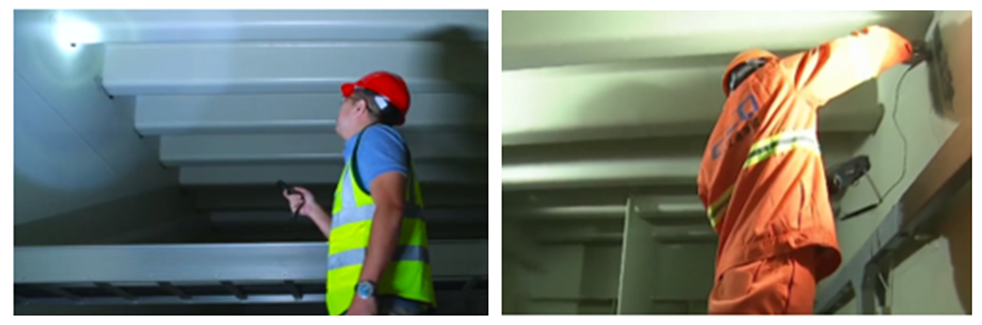
:1. Introduction
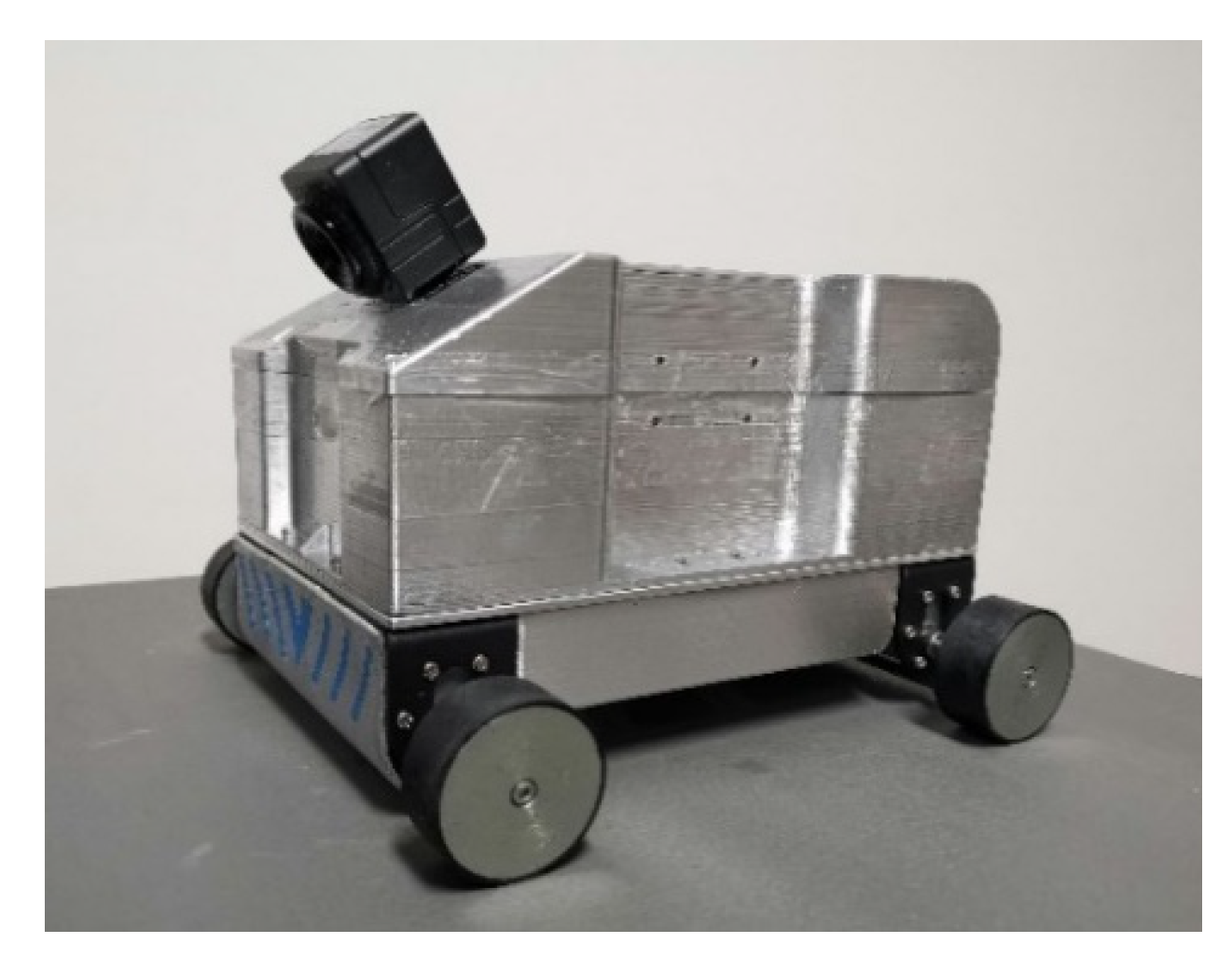
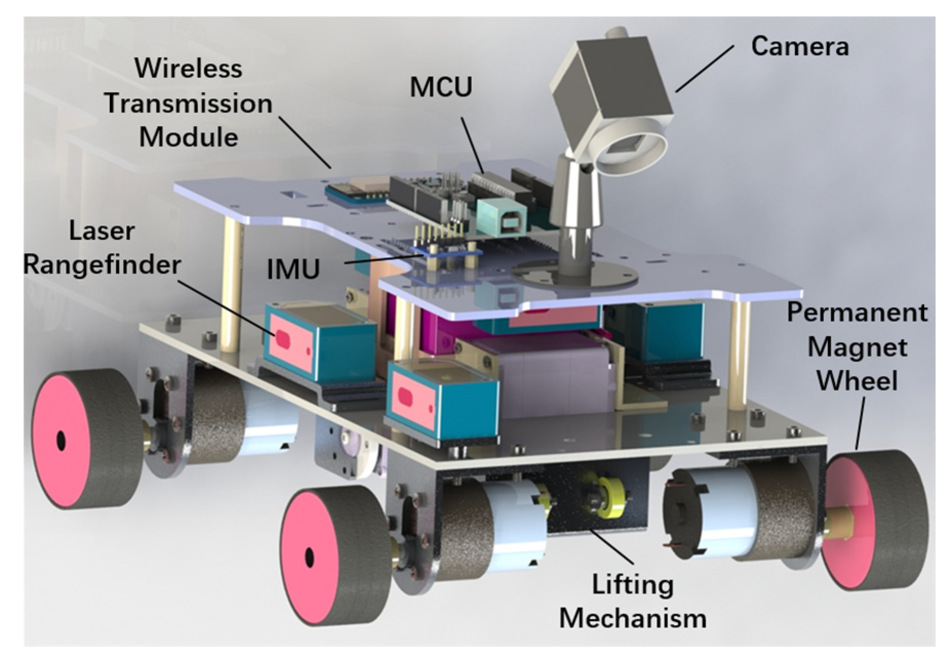
2. Prototype
3. Modeling and Solution
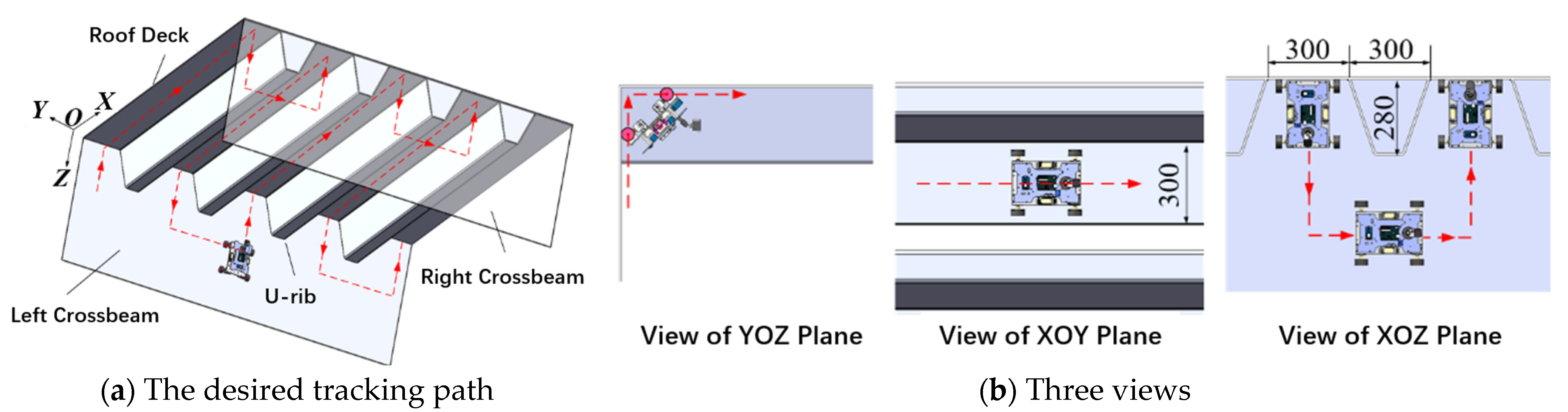
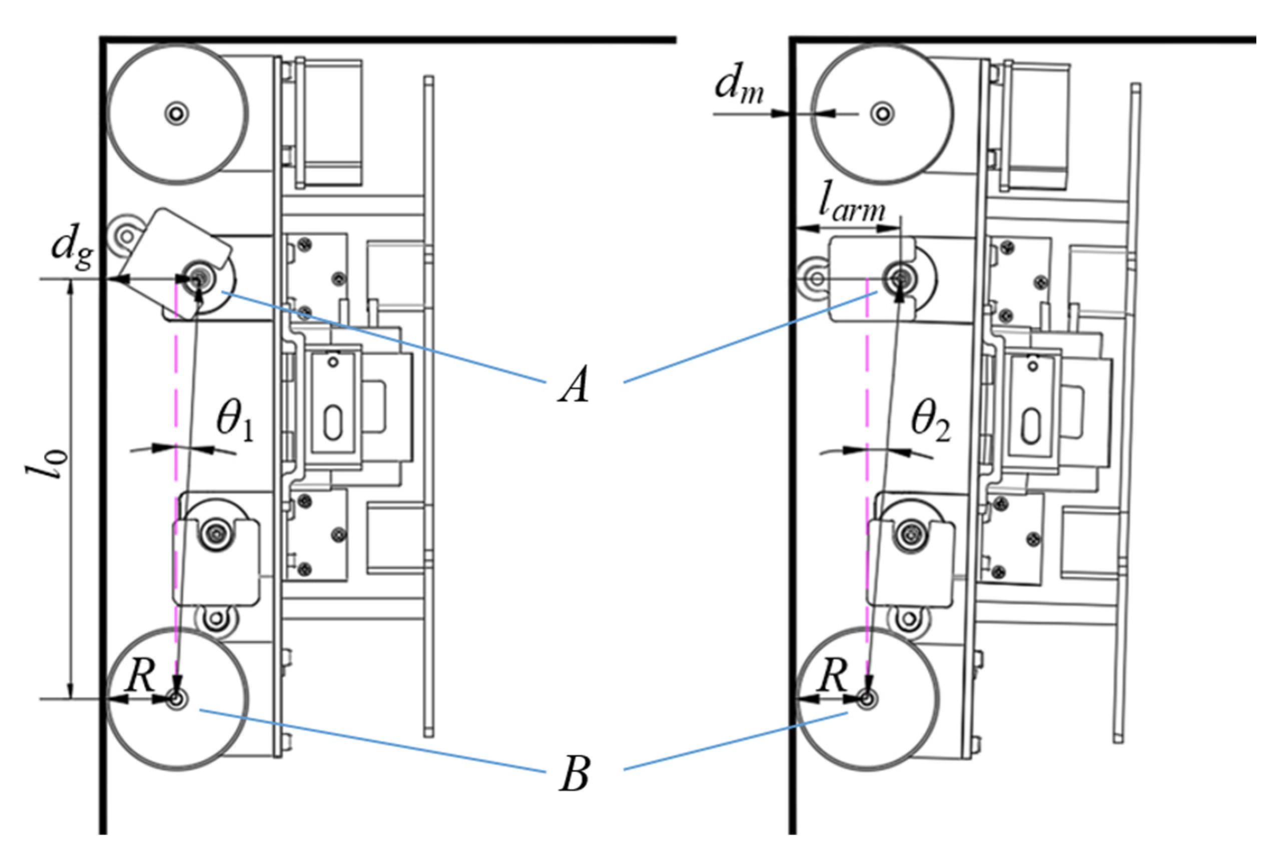
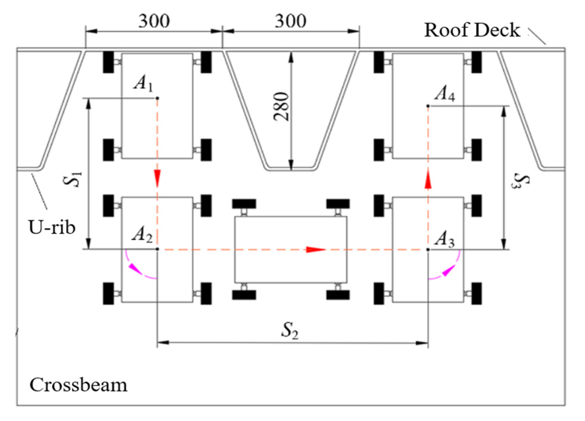
3.1. Crossing a 90° Concave Corner
- θ1—the angle between line AB and the left crossbeam when the lifting mechanism starts to rotate,
- θ2—the angle between line AB and the left crossbeam when the lifting mechanism is reset,
- l0—the vertical distance between A and B,
- larm—the arm length of the lifting mechanism,
- dg—the vertical distance from A to the left crossbeam,
- R—the wheel radius.
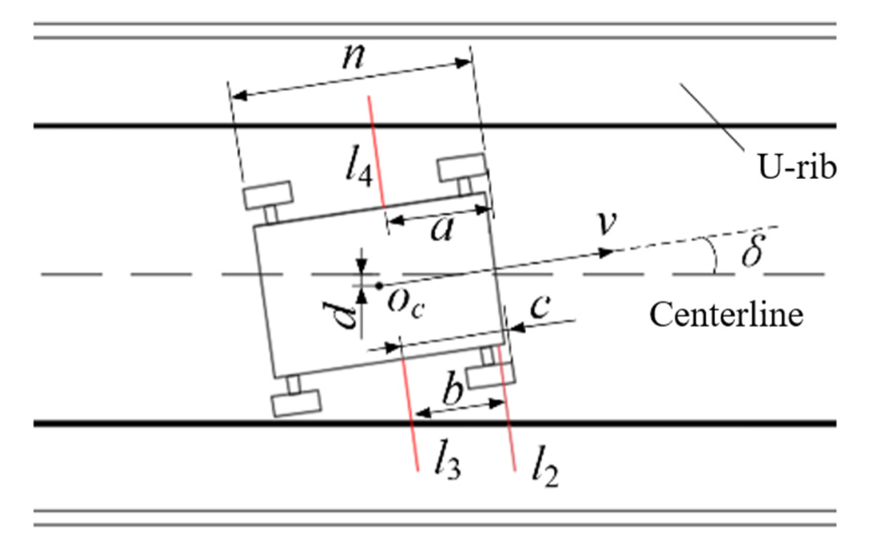
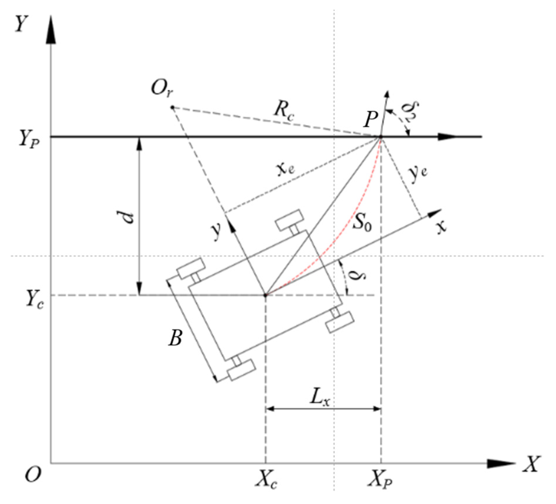
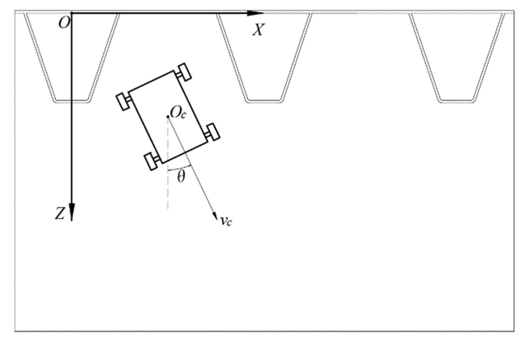
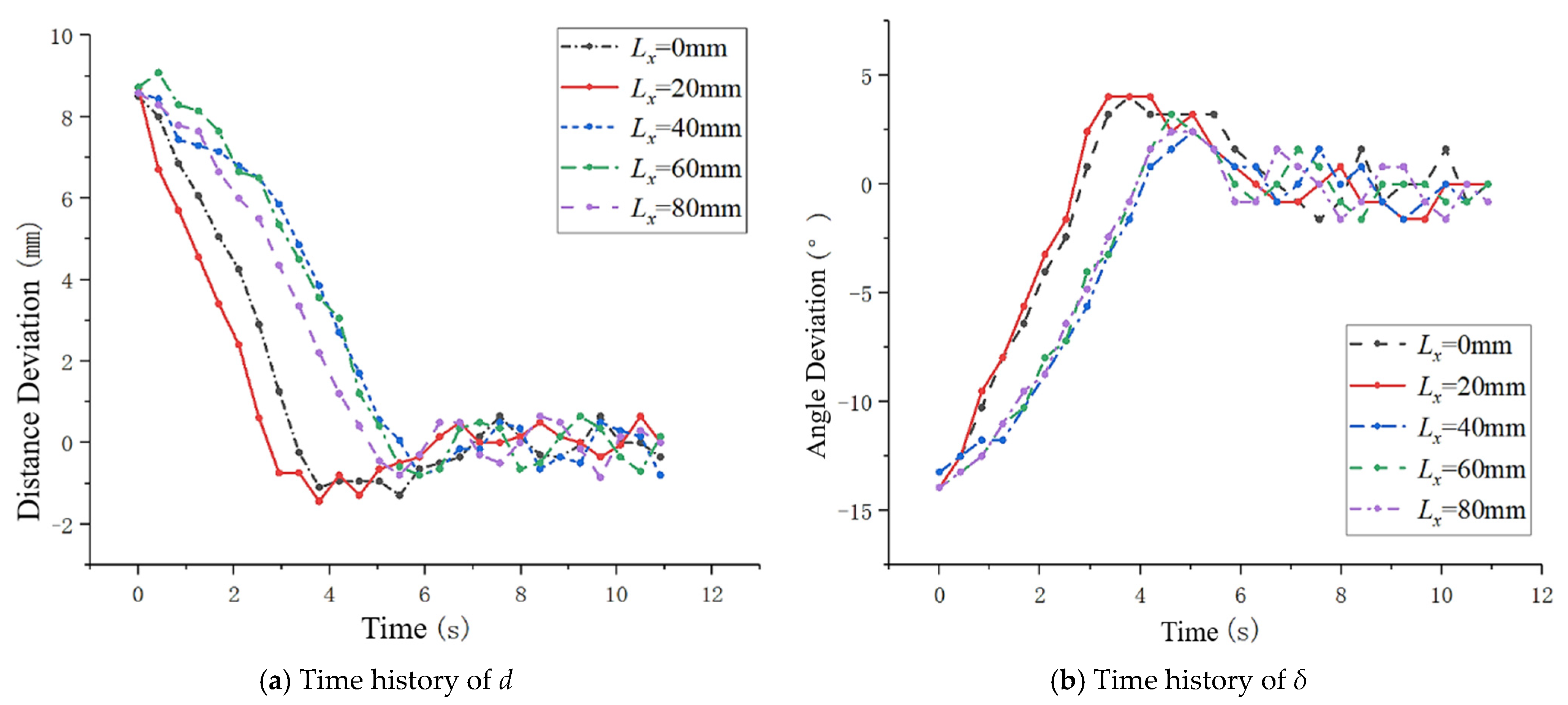
3.2. Tracking the Lane’s Centerline
- a—the distance from laser rangefinder l4 to the front wheel,
- b—the distance between laser rangefinder l2 and l3,
- c—the distance from laser rangefinder l3 to the front wheel,
- n—the length of the wall-climbing robot.
- xe—the abscissa of point P in coordinate system {XOY},
- ye—the ordinate of point P in coordinate system {XOY},
- δ—the yaw deviation,
- Lx—the horizontal distance between Oc and P, which is called the preview distance,
- Rc—the turning radius of Oc.
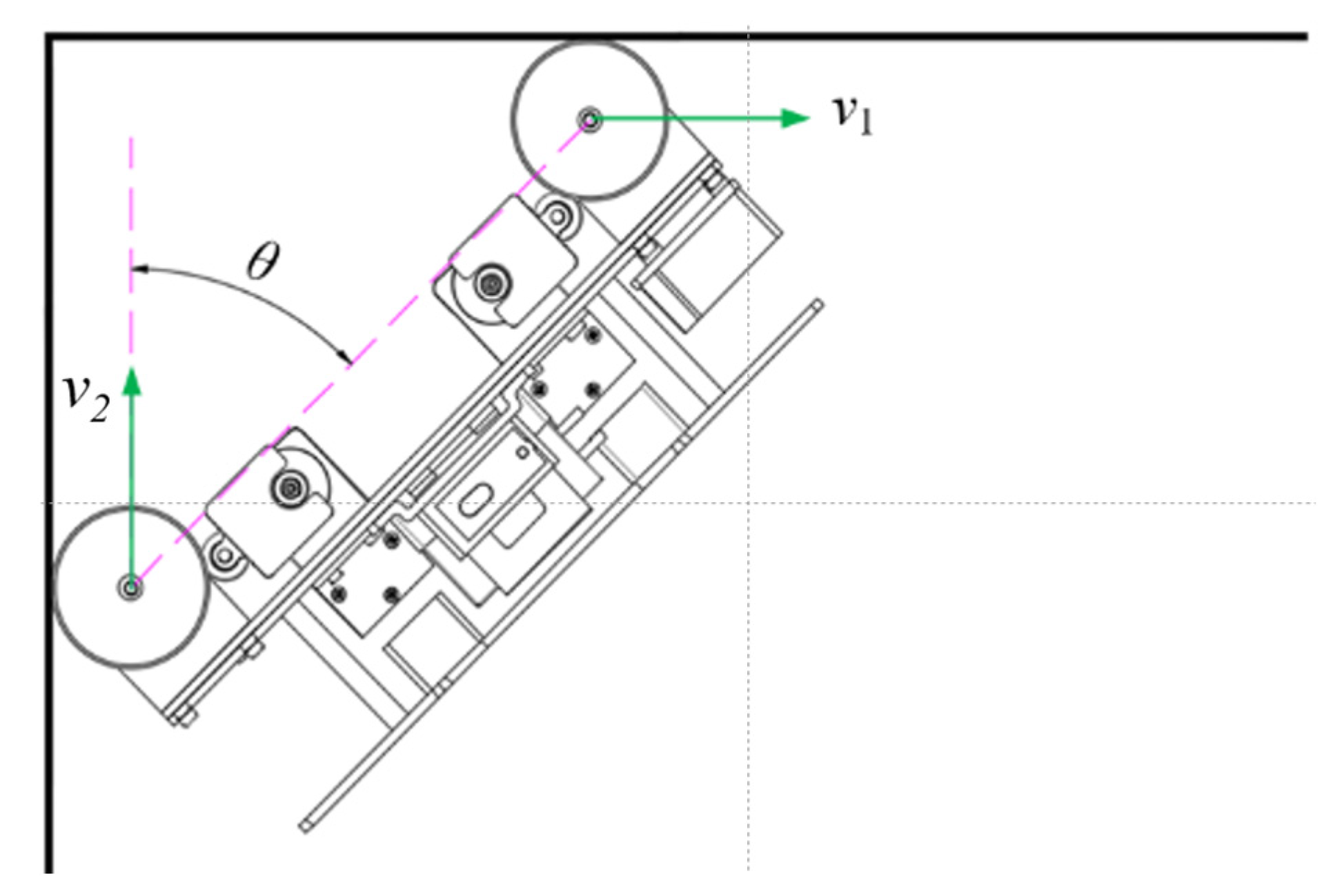
- δ2—the angle between speed direction and the centerline path.
- vl—the speed of the left wheel,
- vr—the speed of the right wheel,
- B—the distance between the left and right wheels.
3.3. Steering to an Adjacent Lane
4. Experiment
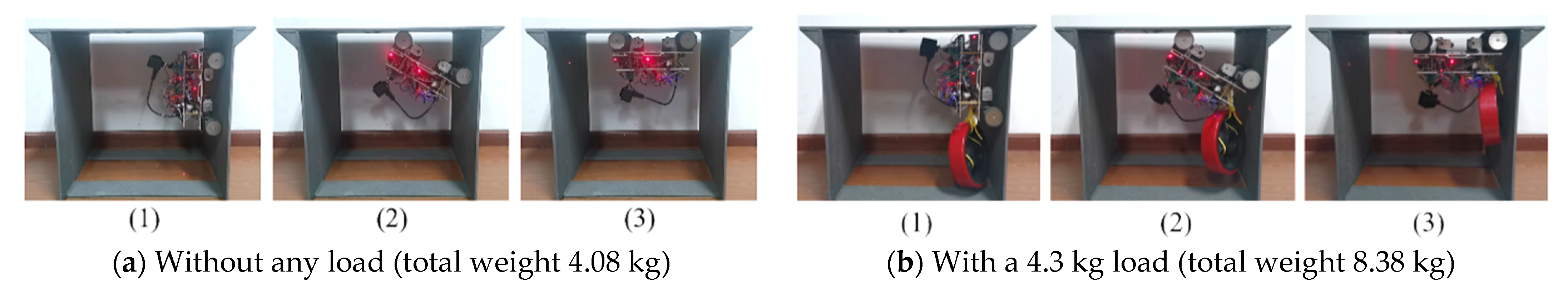
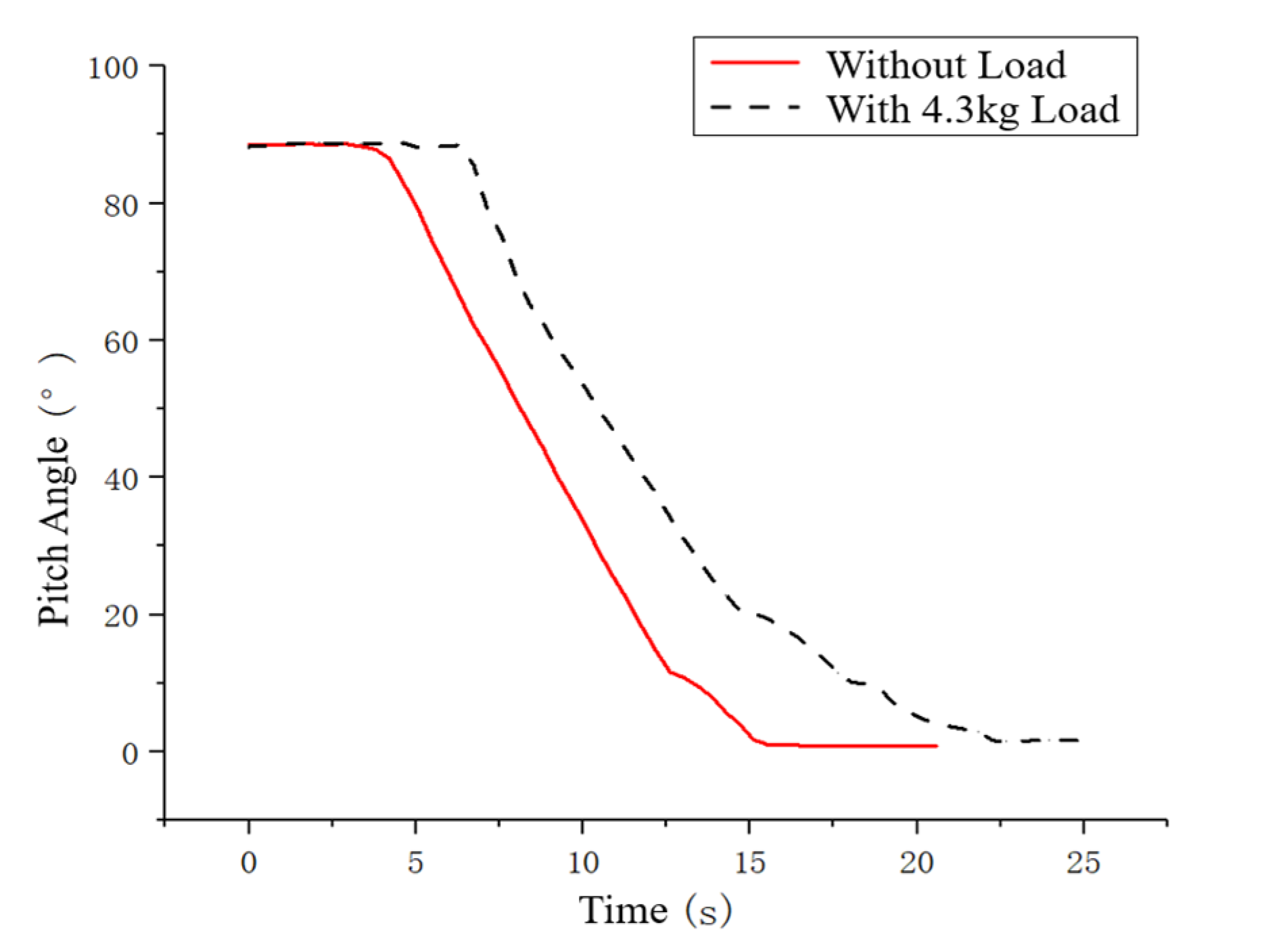
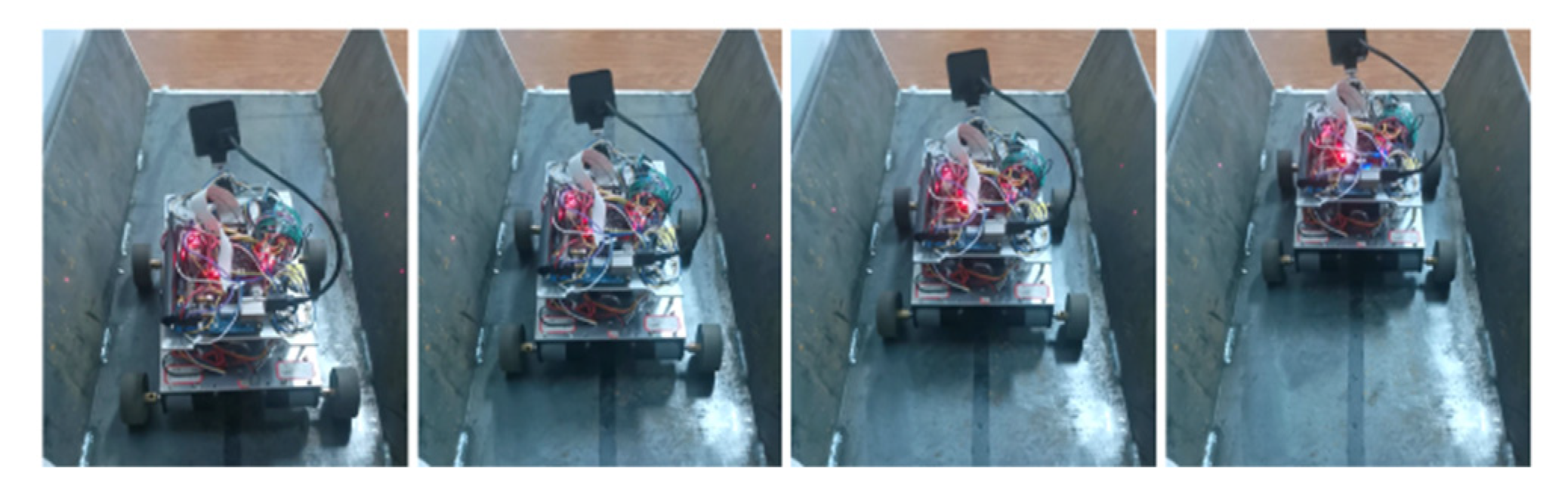
4.1. Experiment on Crossing a 90° Concave Corner
4.2. Experiment on Tracking the Lane’s Centerline
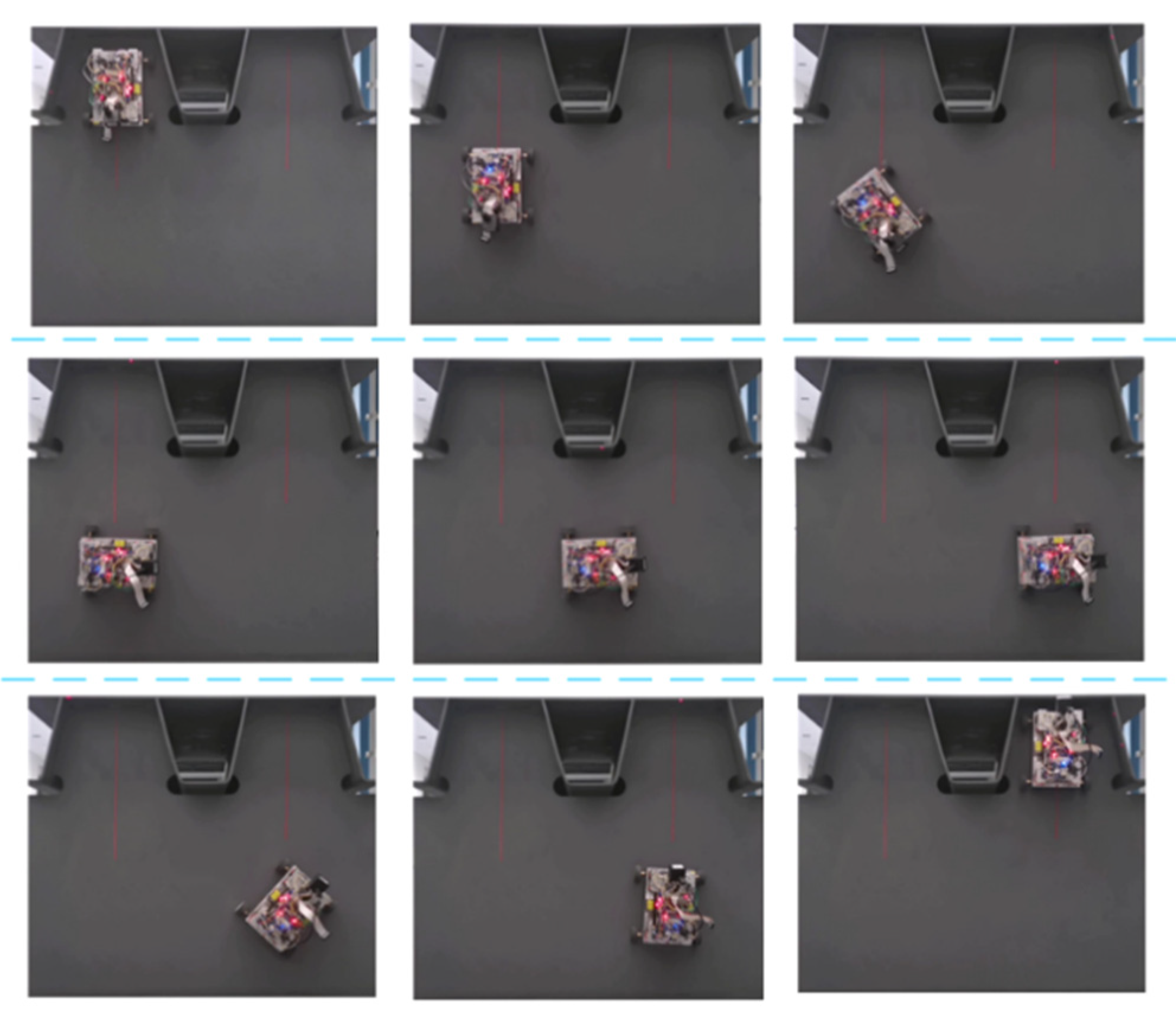
4.3. Experiment on Steering into an Adjacent Lane
5. Conclusions
Author Contributions
Funding
Institutional Review Board Statement
Informed Consent Statement
Data Availability Statement
Conflicts of Interest
References
- Jiang, Z.-S.; Qu, T.; Lu, L.; Ji, B.-H. Research on typical defects analysis of steel box girder and its testing and maintenance technology. J. Disaster Prev. Mitig. Eng. 2011, 31, 572–577. [Google Scholar]
- Qing-hua, Z.; Chuang, C.; Chuan, W.; Jun, L.; Yi-zhi, B. Research on Intelligent Monitoring and Assessment System for Fatigue Damage of Orthotropic Steel Deck Structural System. China J. Highw. Transp. 2018, 31, 66. [Google Scholar]
- Pagano, D.; Liu, D. An approach for real-time motion planning of an inchworm robot in complex steel bridge environments. Robotica 2017, 35, 1280–1309. [Google Scholar] [CrossRef]
- Nguyen, S.T.; Pham, A.Q.; Motley, C.; La, H.M. A practical climbing robot for steel bridge inspection. In Proceedings of the 2020 IEEE International Conference on Robotics and Automation (ICRA), Paris, France, 31 May–31 August 2020; pp. 9322–9328. [Google Scholar]
- Bui, H.-D.; Nguyen, S.; Billah, U.H.; Le, C.; Tavakkoli, A.; La, H.M. Control framework for a hybrid-steel bridge inspection robot. In Proceedings of the 2020 IEEE/RSJ International Conference on Intelligent Robots and Systems (IROS), Las Vegas, NV, USA, 24 October 2020–24 January 2021; pp. 2585–2591. [Google Scholar]
- Liu, Q.; Liu, Y. An approach for auto bridge inspection based on climbing robot. In Proceedings of the 2013 IEEE International Conference on Robotics and Biomimetics (ROBIO), Shenzhen, China, 12–14 December 2013; pp. 2581–2586. [Google Scholar]
- Wang, R.; Kawamura, Y. Development of climbing robot for steel bridge inspection. Ind. Robot Int. J. 2016, 43, 429–447. [Google Scholar] [CrossRef]
- Li, B.; Ushiroda, K.; Yang, L.; Song, Q.; Xiao, J. Wall-climbing robot for non-destructive evaluation using impact-echo and metric learning SVM. Int. J. Intell. Robot. Appl. 2017, 1, 255–270. [Google Scholar] [CrossRef]
- Sirken, A.; Knizhnik, G.; McWilliams, J.; Bergbreiter, S. Bridge risk investigation diagnostic grouped exploratory (BRIDGE) bot. In Proceedings of the 2017 IEEE/RSJ International Conference on Intelligent Robots and Systems (IROS), Vancouver, BC, Canada, 24–28 September 2017; pp. 6526–6532. [Google Scholar]
- Nguyen, S.T.; La, H.M. Development of a steel bridge climbing robot. In Proceedings of the 2019 IEEE/RSJ International Conference on Intelligent Robots and Systems (IROS), Macau, China, 3–8 November 2019; pp. 1912–1917. [Google Scholar]
- La, H.M.; Dinh, T.H.; Pham, N.H.; Ha, Q.P.; Pham, A.Q. Automated robotic monitoring and inspection of steel structures and bridges. Robotica 2019, 37, 947–967. [Google Scholar] [CrossRef] [Green Version]
- Wallace, R.S.; Stentz, A.; Thorpe, C.E.; Moravec, H.P.; Whittaker, W.; Kanade, T. First Results in Robot Road-Following. In Proceedings of the 9th IJCAI, Los Angeles, CA, USA, 20 August 1985; pp. 1089–1095. [Google Scholar]
- Ma, R.; Li, S.; Fu, W. An Improved Algorithm Based on Pure Pursuit Model for Path Tracking. Meas. Control 2011, 30, 93–96. [Google Scholar]
- Morales, J.; Martínez, J.L.; Martínez, M.A.; Mandow, A. Pure-pursuit reactive path tracking for nonholonomic mobile robots with a 2D laser scanner. EURASIP J. Adv. Signal Process. 2009, 2009, 935237. [Google Scholar] [CrossRef] [Green Version]
- Kanayama, Y.; Kimura, Y.; Miyazaki, F.; Noguchi, T. A stable tracking control method for an autonomous mobile robot. In Proceedings of the IEEE International Conference on Robotics and Automation, Cincinnati, OH, USA, 13–18 May 1990; pp. 384–389. [Google Scholar]
- O’Connor, M.L. Carrier-Phase Differential GPS for Automatic Control of Land Vehicles; Stanford University: Stanford, CA, USA, 1998. [Google Scholar]
- Cui, S.M.; Zhang, C.; Wang, J.F.; Zhang, K. Research on path tracking control for vision based intelligent vehicle. Appl. Mech. Mater. 2011, 63, 305–308. [Google Scholar] [CrossRef]
- Zhang, L.; Wu, G.; Guo, X. Path tracking using linear time-varying model predictive control for autonomous vehicle. J. Tongji Univ. Nat. Sci. 2016, 44, 1595–1603. [Google Scholar]
- Jazar, R.N. Vehicle Dynamics: Theory and Application; Springer: Berlin/Heidelberg, Germany, 2017. [Google Scholar]
- Rajamani, R. Lateral vehicle dynamics. In Vehicle Dynamics and Control; Springer: Berlin/Heidelberg, Germany, 2012; pp. 15–46. [Google Scholar]
- Lu, Y.; Liu, H.; Guo, J.; Chen, Z.; Xiang, G.; Liu, Y. Heading Feedback Correction Algorithm for Indoor Pedestrian Navigation Based on Waist MEMS-IMU. J. Chin. Inert. Technol. 2017, 25, 725–730, 737. [Google Scholar]
- Ren, H.; Kazanzides, P. Investigation of attitude tracking using an integrated inertial and magnetic navigation system for hand-held surgical instruments. IEEE/ASME Trans. Mechatron. 2010, 17, 210–217. [Google Scholar] [CrossRef]
- Aghili, F.; Salerno, A. Driftless 3-D attitude determination and positioning of mobile robots by integration of IMU with two RTK GPSs. IEEE/ASME Trans. Mechatron. 2011, 18, 21–31. [Google Scholar] [CrossRef]
- Rui, L.; Duan, J. A path tracking algorithm of intelligent vehicle by preview strategy. In Proceedings of the 32nd Chinese Control Conference, Xi’an, China, 26–28 July 2013; pp. 5630–5635. [Google Scholar]
- Zhang, S.; Zhao, X.; Zhu, G.; Shi, P.; Hao, Y.; Kong, L. Adaptive trajectory tracking control strategy of intelligent vehicle. Int. J. Distrib. Sens. Netw. 2020, 16, 1550147720916988. [Google Scholar] [CrossRef]


| d > 0 | d < 0 | |
|---|---|---|
| δ > 0 | Oc is on the right side of the centerline, and the robot heads to the left of the centerline. | Oc is on the left side of the centerline, and the robot heads to the left of the centerline. |
| δ < 0 | Oc is on the right side of the centerline, and the robot heads to the right of the centerline. | Oc is on the left side of the centerline, and the robot heads to the right of the centerline. |
Publisher’s Note: MDPI stays neutral with regard to jurisdictional claims in published maps and institutional affiliations. |
© 2022 by the authors. Licensee MDPI, Basel, Switzerland. This article is an open access article distributed under the terms and conditions of the Creative Commons Attribution (CC BY) license (https://creativecommons.org/licenses/by/4.0/).
Share and Cite
Song, W.; Wang, Z.; Wang, T.; Ji, D.; Zhu, S. A Path Tracking Method of a Wall-Climbing Robot towards Autonomous Inspection of Steel Box Girder. Machines 2022, 10, 256. https://doi.org/10.3390/machines10040256
Song W, Wang Z, Wang T, Ji D, Zhu S. A Path Tracking Method of a Wall-Climbing Robot towards Autonomous Inspection of Steel Box Girder. Machines. 2022; 10(4):256. https://doi.org/10.3390/machines10040256
Chicago/Turabian StyleSong, Wei, Zhijian Wang, Tong Wang, Daxiong Ji, and Shiqiang Zhu. 2022. "A Path Tracking Method of a Wall-Climbing Robot towards Autonomous Inspection of Steel Box Girder" Machines 10, no. 4: 256. https://doi.org/10.3390/machines10040256