1. Introduction
The globoidal cam indexing mechanism has the advantages of a compact structure, high indexing precision, strong bearing capacity, and good high-speed performance. Consequently, the globoidal cam mechanism plays a pivotal role in mechanical transmission, so it has been widely used in the automatic tool changer (ATC) of computer numerical control (CNC), tobacco machinery, packaging machinery, aerospace, automatic machine tools, and in other fields [
1,
2]. The globoidal indexing cam is a key component in ATC. Because ATC requires a high precision globoidal cam profile, the manufacture and tolerance detection of a high-grade globoidal cam has been a difficult problem for domestic enterprises [
3,
4]. The globoidal cam profile is a non-developable surface in space, which is difficult to process. The profile error of the globoidal cam will directly reduce the output accuracy of the ATC and seriously affect the grasping and positioning accuracy of the manipulator. Five-axis CNC machine tools are generally used for the machining of globoidal cams, so the processing strategy of five-axis CNC machine tools is extremely important. By optimizing the machining strategy, the machining quality of the workpiece can be improved. Amaia Calleja studied the optimal machining strategy for blade turning and milling and tested different strategies and inclination angles to obtain the best blade machining parameters and toolpath strategies [
5]. Therefore, in the manufacturing process, the CNC machine tool should be analyzed in detail to ensure the machining accuracy of the globoidal cam. It is of great practical significance to study the machining error and detection of globoidal cam [
6,
7].
There are several scholars who have studied the machining error of globoidal cams. H.Y. Cheng analyzed the error transfer of globoidal indexing cam mechanism systematically and established the error transfer equation. At the same time, he analyzed the sensitivity made by output precision to each error and established the sensitivity equation [
8]. An improved optimal deviation method to study the more reasonable allocation of globoidal cam mechanism tolerance was proposed by Yang Shiping [
9]. Yin Mingfu researched the influence caused by the center distance error of a globoidal indexing cam machine tool on cam profile error and gave the changing trend of error [
10]. Ji Shuting researched the influence caused by the center distance error of the globoidal indexing cam special machining on the cam profile machining error and drew the influence coefficient curve. She revealed the result that the center distance error leads to the error of globoidal indexing cam profile [
11,
12]. Based on the above research, the influence caused by two rotation shaft errors, three vertical errors, and three linear displacement errors of globoidal indexing cam special machining on the machining error of the globoidal indexing cam profile has been analyzed [
13]. Tang Lin measured in the three-coordinate measuring machine (CMM) and introduced the concept of profile tolerance and helix tolerance [
14]. P.D. Lin and J.F. Hsieh researched the conversion between the measurement coordinates and the theoretical position, to determine the measuring benchmark [
15]. Song Lijuan proposed reversely obtaining the manufacturing tolerance by measuring results [
16], but she did not research the specific contents. Lin Xiaojun proposed a method to compensate the radius by reconstructing the equidistant surface [
17].
However, the measuring speed of the current CMM method is slow and complex. It cannot meet the measurement requirements of globoidal cams in the production line, and it is difficult to fundamentally solve the problem of radius compensation. To solve the incongruity error of the normal vector of globoidal cams in non-equal-diameter machining, Hu Dongfang improved the tool axis vector by using the space linear regression algorithm and the ruled surface generation principle and realized the optimization of the tool path [
18,
19]. In addition, an adaptive compensation method for tool position error was also proposed, which greatly improves the machining accuracy of the globoidal cam in unequal diameter machining. Hammoudi Abderazek applied seven meta-heuristic optimization algorithms to design the disk cam mechanism, formulated three objective design problems, and studied the influence of the selection of the motion law of the follower on the optimal design of the mechanism [
20]. Nguyen proposed a general framework for the kinematic design of cam mechanisms based on non-uniform rational B-splines (NURBS) to reduce inertial forces and vibration trends in cam dynamics of high-speed cam systems [
21]. Sateesh represented the displacement function with NURBS based on standard displacement curves of the follower [
22]. Xia Bizhong realized the design of the cam profile by combining the sixth-order classical spline and the general polynomial spline. After experimental verification, the improved cam profile demonstrated better performance [
23]. In 2018, our team published the conference paper “Analysis and Detection Method for Machining Error of Globoidal Indexing Cam Profile” [
24] and proposed a globoidal cam error detection method based on equidistant contour. Since then, the research has continued, and the globoidal cam design–machining–measuring integrated technology has been formed. In order to ensure the integrity of the research content, the content of the machining error analysis of the machine tool in the 2018 conference paper is included in this paper.
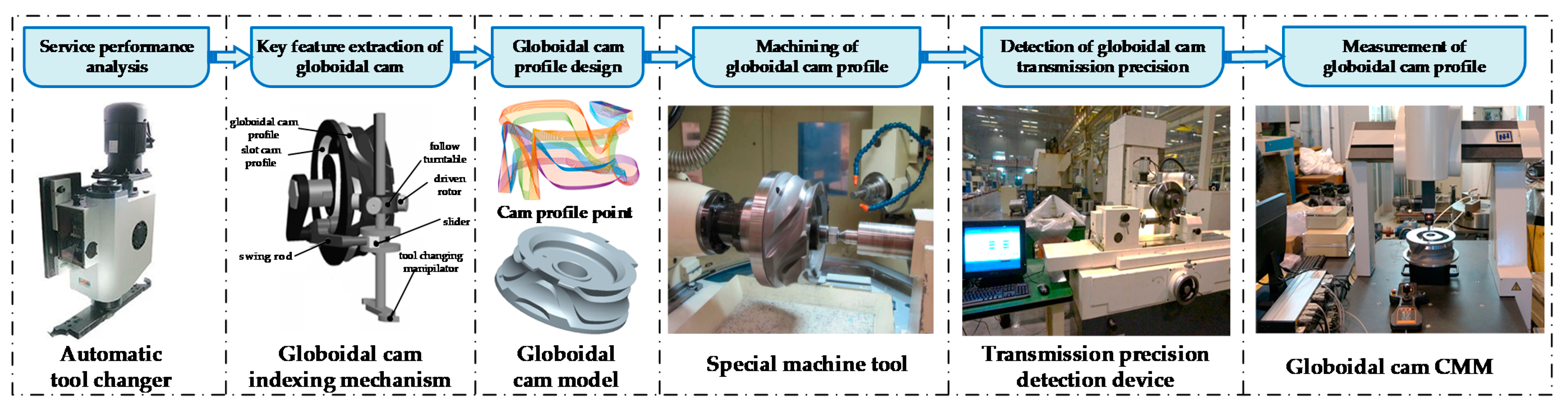
In this paper, we propose a general method of globoidal indexing cam profile machining error analysis and traceability. According to the working principle of the globoidal cam machine, the mathematical model of the globoidal cam profile error is established by using the multi-body system theory. An error evaluation and traceability method based on the equidistant model characteristic line of the globoidal cam is proposed. This method can be used for error compensation in the machining process of the globoidal cam to improve the machining accuracy. The integrated technology of globoidal cam design, manufacture, and measurement is shown in
Figure 1.
The remainder of the paper is organized as follows. An analysis model of globoidal cam machining error based on multi-body system theory is established in
Section 2. The error evaluation and traceability of globoidal cam machining errors are provided out in
Section 3. Finally, the integration of design–machining–measuring–evaluation and traceability of the globoidal cam was realized in the factory, and the experimental research on the profile error detection globoidal cam is introduced in detail in
Section 4, while conclusions are drawn in
Section 5.
3. Evaluation and Traceability of Machining Error of Globoidal Cam
3.1. Measurement Method of Machining Error of Globoidal Cam
By analyzing the characteristics of the globoidal cam profile and the function of CMM, the measurement scheme of the equidistant profile model is proposed. The four-axis measurement system is composed of CMM and the turntable.
As shown in the
Figure 4, the measurement of the characteristic line of the globoidal cam equidistant profile at the specified angle can be realized, the probe radius compensation can be avoided, and the measurement speed and accuracy can be improved. In the actual measurement, the probe is directly compared with the corresponding points on the equidistant profile model of the globoidal cam to complete the error evaluation and traceability.
3.2. Evaluation of Machining Error of Globoidal Cam
The definition of the characteristic lines of the globoidal cam profile surface is given here:
is the axial section when the cam is transferred to
a. When
, the axial section
is the reference plane, and the reference plane remains unchanged in the process of cam rotation. The intersection line of
and
is defined as the characteristic line. The characteristic lines will be on the axial section, and the coordinate points of the working profile that meet the conditions form the axial section characteristic line. The coordinate system for solving the characteristic line of the globoidal cam profile and the axial section profile is shown in
Figure 5.
The planning of the globoidal cam measurement characteristic line is as follows:
- (1)
Measuring characteristic lines in the dwell segments:
- (a)
[358°, 2°], four characteristic lines are planned with 1° as a unit;
- (b)
[52°, 122.5°], 10 characteristic lines are planned with 5° as a unit;
- (c)
[237.5°, 308°], 10 characteristic lines are planned with 5° as a unit.
- (2)
Measuring characteristic lines in the indexing segments:
- (a)
[2°, 52°], 10 characteristic lines are planned with 5° as a unit;
- (b)
[122.5°, 237.5°], 23 characteristic lines are planned with 5° as a unit;
- (c)
[308°, 358°], 10 characteristic lines are planned with 5° as a unit.
To realize error evaluation, three models are established, namely the ideal model, the actual model, and the measured model. In the process of error evaluation, it is necessary to reduce the difference between the measured model and the actual model and to find out the error between the actual model and the ideal model, and then judge whether the cam is qualified. For the error of globoidal cam, different methods are developed to evaluate the error according to different characteristics.
3.2.1. Error Evaluation of the Characteristic Line of the Dwell Segments
The characteristic line of the dwell segments is a straight line. Since the maximum error value of the straight line is generally at the endpoint, the two-point method is used to solve the error. The specific process is:
- (a)
Fit the measurement points to a straight line as the evaluation benchmark;
- (b)
Solve the coordinates of the endpoints of the theoretical characteristic line;
- (c)
Find the distance from the two ends of the theoretical characteristic line to the actual characteristic line, and judge whether it is within the tolerance range.
According to the definition of the axial section and the characteristic line, the characteristic line equation can be expressed as in (9).
Find the distance from the two endpoints to the measured characteristic line, then the larger value is the profile error of the characteristic line at the
α angle, as in (12).
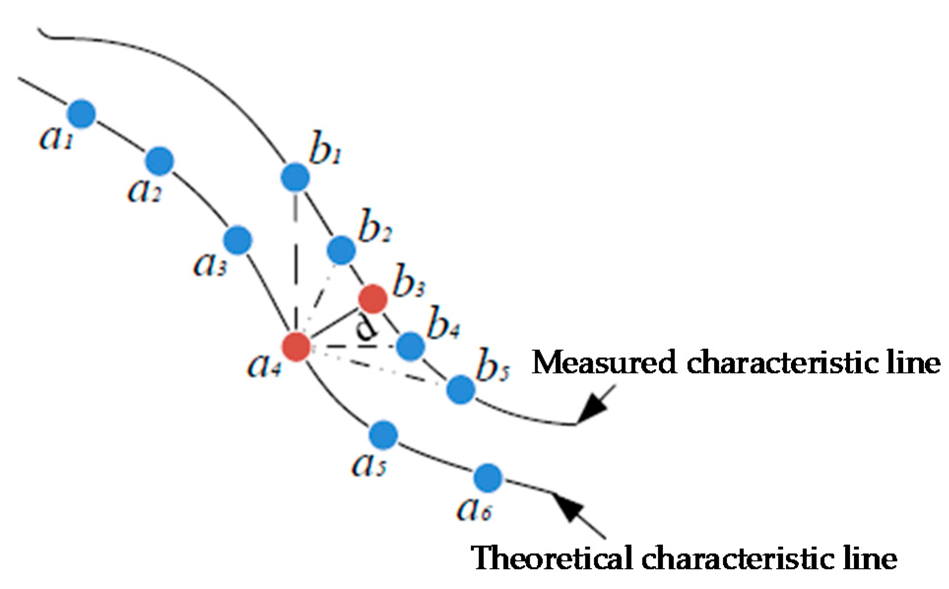
3.2.2. Evaluation of the Error of the Characteristic Line of the Indexing Segments
The characteristic line of the indexing segments is a curve, and the minimum area evaluation is used for error evaluation, as shown in
Figure 6. The specific process is:
- (a)
Use NURBS to fit the actual measurement points into a curve, as the error evaluation benchmark;
- (b)
Solve the coordinates of the theoretical characteristic points;
- (c)
Use the segmentation search method to determine the shortest distance from the theoretical characteristic point to the actual characteristic curve, and judge whether it is within the tolerance range.
For the theoretical characteristic point
, there is only one point
located on the measured characteristic line, so that the distance between
and the measured characteristic line is minimized, as in (13).
According to the definition of line profile error, the maximum distance from each theoretical characteristic point to the measured characteristic point is taken as the line profile error, as in (14).
3.2.3. Evaluation of Surface Profile Error
In this paper, the section method is used as the evaluation method of the surface profile error. The indexing segments and the dwell segments need to be evaluated for the surface profile respectively. Solve the errors of multiple globoidal cam characteristic lines separately and take the maximum value of these errors as the surface profile error.
After the error evaluation, it is necessary to judge whether the globoidal cam meets the accuracy requirements. If it meets the requirements, there is no need to trace the error. If it does not meet the requirements, it is necessary to trace the error to the test results.
3.3. Traceability of Machining Errors of Globoidal Cam
Errors are grouped according to machine tool error sensitivity. In the evaluation process of the error in the dwell segments, the errors that have no effect on the profile machining of the globoidal cam in the dwell segments can be temporarily ignored, and the source of the influential errors can be traced. The rest of the errors are traceable in the indexing segments.
The sequential quadratic programming algorithm has the advantages of fast convergence speed and high computational efficiency. In this paper, it is used as an optimization algorithm for error tracing. The optimization model needs to be established first. The general mathematical problem model of nonlinear constraints is as in (16).
: Decision variables
: Objective function
: Inequality constraint function
: Equality constraint function
The optimization model of processing error traceability is as follows.
- (1)
Design variables: The design variables of error traceability are all errors of machine tool processing, and the method of segmental traceability is adopted.
- (2)
Constraints: The constraints of this optimization model need to ensure that the calculation point is located on the globoidal cam profile. The error model of the globoidal cam profile is summarized as in (17).
where
is the theoretical profile point coordinates (
x, y, z) of the globoidal cam with error. α is the cam angle, B is the tool depth, and X is the cam profile error.
- (3)
Objective function: An objective function based on least squares theory is proposed, as in (19).
where
n is the number of measurement points.
,
, and
are the coordinate values of the points after alignment adjustment, which are called actual coordinate values. When using the sequential quadratic programming method to trace the source of the error, it is finally necessary to obtain a set of error values to maximize the value of the fitness function
f(x). At this time, this set of errors is the error traceability result.
4. Experimental Research on Profile Error Detection for Globoidal Cam
To verify the correctness and feasibility of the machining error analysis and traceability method of the globoidal indexing cam, the accuracy of the indexing transmission was tested by the rolling experiment of the globoidal cam. If it does not meet the requirements, a CMM can be used to detect the machining error of the working profile of the globoidal cam, feeding back the error traceability results to the processing link, to improve the machining quality of the cam through error compensation. Thus, the integrated method of globoidal cam design, machining, and measurement is realized. This experiment was carried out in the production and processing workshop of Beiyi Machine Tool Co., Ltd. (Xiantao, China), and the experimental object is the TC40 globoidal cam.
4.1. Testing Experiment of Globoidal Cam Indexing Transmission Accuracy
The globoidal cam indexing transmission detection system is shown in
Figure 7, including a rolling globoidal cam detector, a control cabinet, and an industrial computer. The transmission accuracy detection system of the globoidal cam indexing mechanism can detect the transmission accuracy of various types of globoidal cams. The rolling globoidal cam detector has five motion axes, namely
X, Y, Z, A, and
B, among which
X and
Y are manual axes,
Z and
A are
AC motor drive axes, and the
B axis is a servo motor drive axis.
A and
B axes are equipped with photoelectric encoders, and
X, Y, and
Z axes are equipped with grating rulers. The control and measurement process of the transmission accuracy detection realizes the control of each axis motor through the measurement and control software of the industrial computer and collects and displays the signals of each grating ruler and encoder.
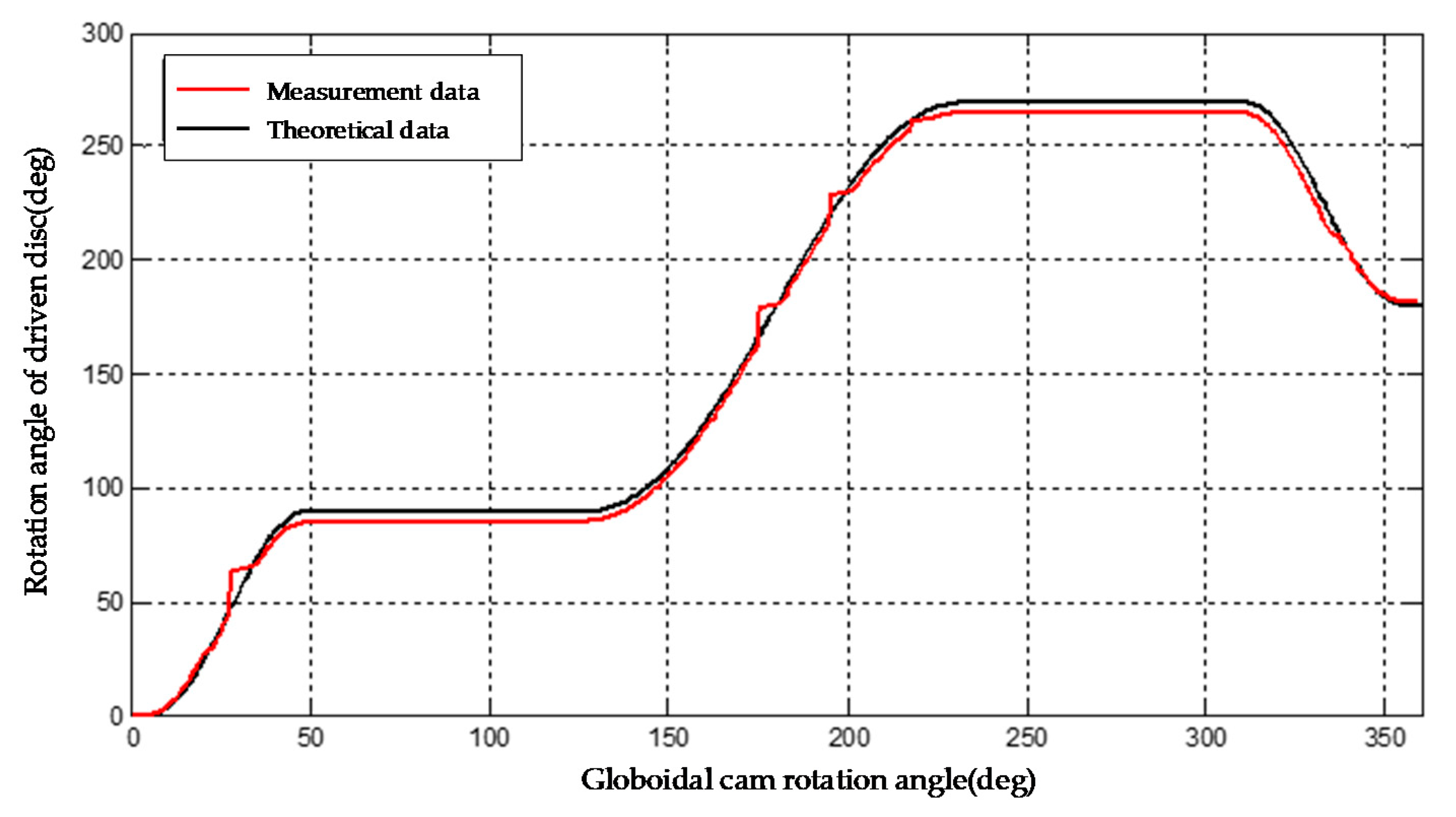
After completing the field detection experiment, the collected data need to be analyzed and processed. The encoder data collected by the globoidal cam transmission accuracy detection system need to be phase-matched with the shaft rotation angle of the globoidal cam and the driven shaft rotation angle, then compared with the theoretical motion law curve to analyze the transmission accuracy. In this example, the modified sinusoidal motion law can be used to calculate the relationship between globoidal cam angle α and the rotational angle β of the driven turntable at different motion positions.
Through the comparison between the globoidal cam I transmission curve and the theoretical transmission curve, as shown in
Figure 8, it can be analyzed that there are obvious differences with the theoretical curve, especially in the two dwell segments, and the angular displacement of the follower is obviously small. There are many factors affecting the transmission accuracy of the globoidal cam. The globoidal cam profile error caused by machining is the main factor affecting the transmission accuracy. This requires measuring and evaluating the machining error of the globoidal cam profile and improving the machining quality after the traceability and compensation of the machining error.
4.2. Measurement Experiment Process
The experimental device for measuring the error of the globoidal cam profile is shown in
Figure 9. The device mainly consists of a three-coordinate measuring machine, a turntable system, and a globoidal cam to be measured. The model of the CMM is NHC-Y564, and the measuring stroke is as follows: X-axis-500 mm, Y-axis-600 mm, Z-axis-400 mm. The turntable system includes a turntable, positioning module, circular grating angle measurement system, driving stepper motor, turntable controller, and driver. The turntable is controlled by a stepping motor, a single-chip microcomputer is used as the main control chip of the stepping motor control system, and the rotation angle of the turntable is displayed in real time through a circular grating angle measurement system. It can meet the measurement requirements of TC40 and TC50 series of globoidal cams. The model of globoidal cam to be tested is TC40, and its size parameter is as follows: thickness 97 mm, maximum diameter 265 mm.
Measure the characteristic points on the characteristic line of the specific cam angle position after the theoretical model matches the angle position of the cam to be measured. After all characteristic points are measured, adjust the turntable to the next position to be measured through the turntable control panel, read the angle displayed by the digital display, rotate and match the theoretical model, and complete the measurement of the next characteristic line. Repeat the above process until all characteristic lines are measured. According to the measurement plan of the characteristic line, the globoidal cam is measured in sections according to the above measurement process. After the measurement is completed, the measurement results are exported. The error evaluation and traceability at different periods are carried out according to the actual measurement data.
The measurement result of CMM is composed of two parts: the coordinate value of the theoretical characteristic point and the coordinate value of the measured characteristic point. The data format of results is
PT (X, Y, Z). By exporting a file in PDF format, the measuring position of the probe is displayed as shown in
Figure 10a and the measuring data are shown in
Figure 10b.
4.3. Error Evaluation for Globoidal Cam
4.3.1. Evaluation of the Error of the Characteristic Line of the Indexing Segment
In the period of indexing segment 1, the cam angle range is [2°, 52°], and 10 characteristic lines are planned at 5° intervals. In the actual measurement, it is not necessary to precisely control the rotation angle of the turntable. When the turntable stops, record the relative angle measured by the circular grating relative to the reference axis section, and calculate the theoretical characteristic line according to the cam rotation angle to match the measured data to complete the error evaluation. In the period of indexing segment 1, taking the third characteristic line
(cam rotation angle α = 15.15°) as an example, the evaluation process of the contour error of the indexing segment line is introduced in detail. The measurement data of the characteristic points are shown in
Table 4.
4.3.2. Evaluation of the Characteristic Line Error of the Dwell Segment
According to the result of the characteristic line measurement plan, the cam rotation angle interval at the dwell segment 2 is [52°, 122.5°]. In order to evaluate the profile error of the dwell segment line of the globoidal cam, taking the third characteristic line
as an example, the detection is completed according to the detection process. The theoretical and measured points of the cambered cam are summarized as shown in
Table 5.
In this paper, the measurement method of the equidistant profile axis section characteristic line adopted is consistent with the section method in the surface profile error evaluation method, so the section method is adopted as the evaluation method of the globoidal cam surface profile error. The indexing segment and the dwell segment need to be evaluated for the surface profile respectively.
The detected globoidal cam profile error is within the tolerance range of the profile error determined, and it is rated as a qualified product, which is consistent with the detection result of the plug gauge in the production workshop, indicating the correctness of the assessment method.
4.4. Error Traceability for Globoidal Cam
Due to the large number of processing error factors, this paper selects 8 errors to trace the source of the error, which are as follows:
- (1)
Linear displacement error of the main shaft along X direction
- (2)
Linear displacement error of the main shaft along Y direction
- (3)
Center distance error
- (4)
Cam angle error
- (5)
Follower angle error
- (6)
Angular displacement error of A axis around X direction
- (7)
Angular displacement error of A axis around Y direction
- (8)
B axis angular displacement error around X direction
According to the method of segmental traceability of machining errors proposed in this paper, the error factors affecting the dwell are found in the dwell segments, and the other errors are found in the indexing segment. By solving various processing error sensitivity coefficients, the displacement error of the spindle along the Y direction , the angular displacement error of the A axis around the X direction , the angular displacement error of the B axis around the X direction , and the cam angle error have no effect in the dwell segment.
First, in the dwell segment, according to the measurement characteristic line, the line displacement error of the spindle along the
X direction
, the center distance error
, the follower angle error
, and the angular displacement error of the
A axis around the
Y direction
are traced to the source. Then, trace the source of the remaining four errors by using the measuring characteristic line of the indexing segment. The traceability results are shown in
Table 6.
4.5. Testing Experiment of Transmission Accuracy
According to the result of error tracing, adjust the program of the globoidal cam machining machine, carry out error compensation, and test the transmission accuracy of the globoidal cam after compensation. The transmission curve of the globoidal cam II is shown in
Figure 11, which is basically consistent with the ideal cam, and the machining quality is significantly improved compared with the globoidal cam I, which shows that the proposed method for analyzing the machining error and tracing the source of the globoidal indexing cam is feasible.
5. Discussion
The globoidal cam indexing mechanism is mainly composed of globoidal cams, turntables, boxes, camshafts, turntable shafts, bearings, and other components. The output accuracy of the globoidal cam indexing mechanism is related to the manufacture of each component and the assembly of each component. The error sources of the globoidal cam indexing mechanism are mainly the machining geometric errors of its components, as well as the assembly errors of the globoidal cam and the turntable, the camshaft, the turntable shaft, and the box. These errors have an impact on the output motion accuracy of the globoidal cam indexing mechanism.
The machining error of the globoidal cam indexing mechanism is a major factor that affects the indexing accuracy of the globoidal cam indexing mechanism, and it is also a difficult factor to analyze. In this paper, the assembly of the indexing mechanism box is not carried out, and only the machining error of the globoidal cam profile and the center distance error are analyzed. The correlation between the machining error of the globoidal cam and the transmission precision of the globoidal cam indexing mechanism, as well as the influence of the center distance adjustment on the transmission precision, are found. This provides a theoretical basis for designing the precision distribution, processing technology adjustment, and formulating the precision index system of the special processing machine tool for globoidal cams.


