Article

The Modelling and Analysis of Micro-Milling Forces for Fabricating Thin-Walled Micro-Parts Considering Machining Dynamics

1
School of Mechanical and Electrical Engineering, Harbin Institute of Technology, Harbin 150001, China
2
Department of Mechanical and Aerospace Engineering, Brunel University London, Uxbridge UB8 3PH, UK
*
Author to whom correspondence should be addressed.
Machines 2022, 10(3), 217; https://doi.org/10.3390/machines10030217
Submission received: 24 February 2022 / Revised: 14 March 2022 / Accepted: 16 March 2022 / Published: 20 March 2022

Abstract

:
In the fabrication process of thin-walled micro-parts, both micro-cutting tools and thin-walled micro-parts have the characteristics of small size and low stiffness. Therefore, the regenerative chatter during the machining process cannot be ignored. The influence of the tool runout error and actual trochoidal trajectories of the cutting edge on micro-milling forces should also be considered comprehensively. In this paper, the tool runout error in the micro-milling process is first analysed, and an instantaneous undeformed chip thickness model is established considering the runout error. On this basis, the dynamic deformation of the micro-cutting tool and thin-walled micro-part is studied, and an instantaneous, undeformed, chip-thickness model is proposed with the consideration of both the runout error and dynamic deformation. The dynamic parameters of the machining system are obtained using the receptance coupling method. Finally, thin-walled micro-part machining experiments are carried out, and the obtained results of micro-milling force simulation based on the proposed model are compared with the experimental results. The results indicate that the micro-milling force modelling, by taking the influence of machining dynamics into account, has better prediction accuracy, and the difference between the predicted resultant forces and the experimental results is less than 11%.

1. Introduction

Thin-walled micro-parts generally refer to thin-walled structures with a thickness less than 100 μm and a height-to-thickness ratio greater than 5. They are widely used in the medical, aviation, and aerospace industries [1]. Among them, Ti-6Al-4V alloy is widely used, considering its high specific strength, specific stiffness, and good biocompatibility [2]. Micro-milling technology has superior characteristics, including high processing efficiency, high machining accuracy, and a wide range of processing materials, so it is used as an effective means of thin-walled micro-part fabrication. The diameter of the micro-milling tool is typically between 100 μm and 1 mm, and usually, it has to bear more stress than the traditional cutting tool and is more prone to tool wear and breakage [3]. The stiffness of the thin-walled micro-structure is also weak, which makes the regenerative chatters nonnegligible during the machining process.
Cutting force is an important index for the machining quality and cutting tool status. Therefore, it is crucial to establish a modelling and analysis approach that can be used for predicting the cutting forces and consequently the process optimisation in thin-walled micro-part fabrication in particular. The mechanistic cutting force modelling combines the advantages of analytical and empirical methods. Therefore, it has been widely studied. The cutting force is proportional to the instantaneous undeformed chip thickness (IUCT) in the mechanistic model. Therefore, IUCT modelling is the basis for establishing the cutting force model [4]. There are differences in mechanism between the micro-milling and traditional processes, due to the scale reduction. Therefore, the traditional method for calculating the IUCT is not suitable for micro-milling. The actual trajectory of the cutting edge during the micro-milling process is trochoidal. However, the tool runout error and the dynamic deformation of the machining system can cause variations in trajectory and IUCT, so the precise modelling of IUCT remains a challenge, especially for thin-walled parts micro-milling.
Considering the differences between micro-milling and conventional milling, Bao and Tansel proposed an IUCT model based on the trochoidal trajectory of the cutting edge. The prediction accuracy of the present cutting force model is 15% higher than that of the traditional milling force model [5]. At the same time, due to the decrease in tool diameter, the ratio of tool runout to tool diameter cannot be ignored [6]. On this basis, many researchers have proposed cutting thickness models by considering tool runout [7,8,9]. Afazov’s research shows that when the feed per tooth is small, the influence of tool runout on the IUCT is more significant [10]. Some researchers pointed out that the cutting force model, considering both the influence of the helix angle and tool runout, has better prediction accuracy, and the simulated cutting force is in good agreement with the experimental values [11]. In addition, the tool runout error can result in cutting force fluctuations and uneven wear in the cutting edge [12].
Different from macro-machining, the cutting edge radius of the micro-machining tool and the IUCT are both in the micrometre scale. By using finite element analysis, some researchers have indicated that the cutting edge radius affects the deformation process of material removal [13]. In the micro-milling process, when the cutting thickness is less than the critical value, the material removal mechanism changes from a shear-dominated area to a plough-dominated area, and no chips will be formed [14,15]. It is found that there is a numerical relationship between the minimum cutting thickness and the cutting edge radius [16]. Some force models are proposed considering shearing and ploughing effects [17,18], in which the cutting force in the ploughing stage is proportional to the contact volume between the cutting tool and the workpiece [6,19].
Due to the low stiffness of micro-cutting tools and thin-walled micro-parts, regenerative chatter is unavoidable under the action of cutting force. Chen established an IUCT model that considers both tool runout and tool–workpiece dynamic deformation, according to which a micro-milling force model was established. The results show that the proposed cutting force model had better prediction accuracy than previous ones, especially when the feed rate was small [20]. Mohammad established a micro-milling force model taking ploughing effect, elastic recovery, tool runout, and dynamic characteristics into account [19]. The dynamic parameters cannot be obtained directly in micro-milling. In some studies, the finite element simulation method is used to obtain the dynamic parameters of the micro-milling system [20]. The receptance coupling method is also employed in acquiring the dynamic parameters [19,21,22,23,24].
The thickness of thin-walled micro-parts is in the micron scale, and the height-to-thickness ratio is relatively large. Therefore, except for the influence of tool runout error and the actual cutting edge trajectory, the dynamics in the micro-milling process cannot be ignored, especially the dynamics of the micro-tool. However, the relevant research on the cutting force modelling in micro-milling thin-walled parts is still nonexistent.
Hence, this paper proposes a micro-milling forces modelling method for thin-walled micro-part fabrication, and further in-depth analysis is conducted. The modelling and analysis are evaluated and validated by well-designed micro-milling experiments. The results show that the micro-milling forces modelling considering the machining system dynamics have good prediction accuracy.

2. Modelling of IUCT

The cutting force is proportional to the IUCT in the mechanistic micro-milling force model. Therefore, the calculation of the IUCT is the premise for the micro-milling forces model. In addition to the tool runout error, the influence of the tool–workpiece dynamic deformation error on the IUCT and micro-milling force cannot be ignored, as shown in Figure 1. On the basis of the traditional micro-milling force model, the influence of dynamic characteristics is taken into account. In this section, a model for the accurate IUCT calculation is presented based on the real cutting-edge trajectories of the micro-milling cutter. It can be observed that the cutting force prediction is a feedback process.

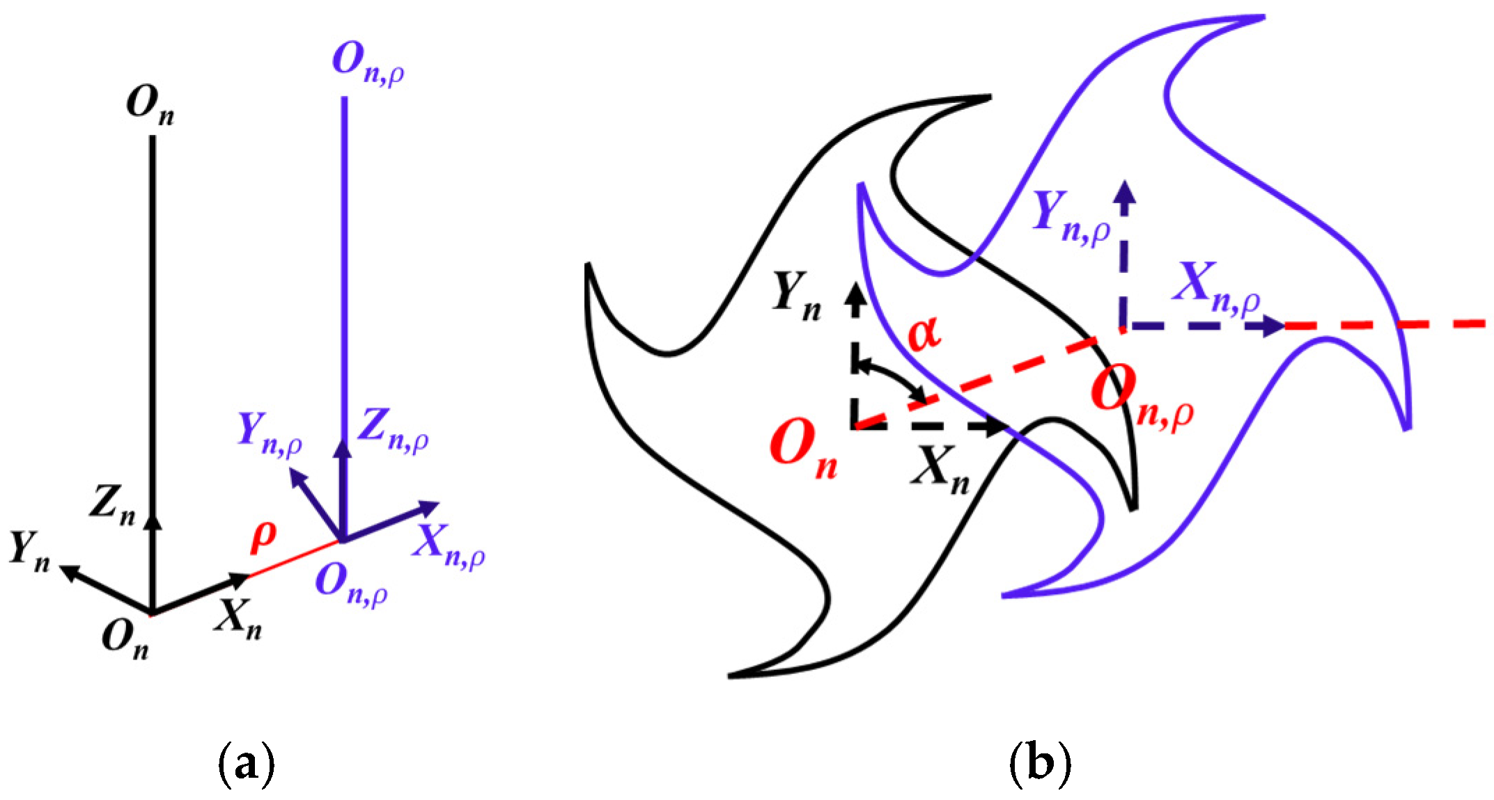
2.1. Modelling of the Cutting-Edge Trajectories

As shown in Figure 2, the micro-milling cutter is equally divided into K micro-elements along the z-axis direction. The corresponding element cutting force is acted on to each micro-element. The element cutting force has three components: radial, normal, and axial, in which the axial component is relatively small [25].
Due to the influence of the helix angle, the corresponding time of each micro-element at height z can be expressed as Equation (1).
t i ( z ) = t 0 z ω a p arccos ( 2 R 2 a p 2 tan 2 β 2 R 2 ) , z = k a p K
where β is the helix angle of the cutting tool, R is the tool radius, ω is the angular velocity of the spindle rotation, ap is the axial depth of cut, and K is the number of micro-elements.
Therefore, the angular position of the jth cutting edge at any time can be expressed as follows:
φ [ t i ( z ) ] = ω [ t i ( z ) ] z tan β R + ( j 1 ) 2 π N t , z = k a p K
where Nt denotes the tooth number.
The central position of the ith tool micro-element can be expressed as Equation (3).
x a [ t i ( z ) ] = x n [ t i ( z ) ] + x ρ [ t i ( z ) ] + x d [ t i ( z ) ] y a [ t i ( z ) ] = y n [ t i ( z ) ] + y ρ [ t i ( z ) ] + y d [ t i ( z ) ]
where xa[ti(z)] and ya[ti(z)], respectively, represent the actual coordinates of the cutting-edge centre at height z; xn[ti(z)] and yn[ti(z)], respectively, represent the nominal coordinates of the cutting-edge centre at height z. It can be expressed as follows:
x n [ t i ( z ) ] = f t i ( z ) y n [ t i ( z ) ] = 0
where xp[ti(z)] and yp[ti(z)], respectively, denote the position deviation caused by the tool runout error, as shown in Figure 3.
Additionally, they can be expressed as Equation (5).
x ρ [ t i ( z ) ] = ρ sin [ α + ω t i ( z ) ] y ρ [ t i ( z ) ] = ρ cos [ α + ω t i ( z ) ]
where ρ and α represent the runout error value and position angle of the cutting tool, respectively. xd[ti(z)] and yd[ti(z)] represent the position deviation caused by the dynamic deformation between the cutting tool and workpiece in the x and y direction, respectively.
According to the machining system dynamics, the dynamic deformation of the micro-milling tool and thin-walled micro-parts can be obtained from Equation (6).
x p [ t i ( z ) ] = 0 t F x ( ξ ) g p x ( t ξ ) d ξ , ( p = t , w ) y p [ t i ( z ) ] = 0 t F y ( ξ ) g p y ( t ξ ) d ξ , ( p = t , w )
where Fx and Fy are the cutting force in the x and y directions; gpx (p = t, w) are the impulse responses of the cutting tool and thin-walled micro-part in the x direction, respectively; gpy (p = t, w) is the impulse responses of the cutting tool and thin-walled micro-part in the y direction, respectively. Therefore, the relative displacement between the tool and workpiece can be obtained as follows:
x t w [ t i ( z ) ] = x t [ t i ( z ) ] x w [ t i ( z ) ] y t w [ t i ( z ) ] = y t [ t i ( z ) ] y w [ t i ( z ) ]
The dynamic deformation and the relative displacement of the previous cutting cycle can be expressed as Equations (8) and (9), respectively.
x p [ t i ( z ) ] = 0 t F x ( ξ ) g p x ( t ξ ) d ξ , ( p = t , w ) y p [ t i ( z ) ] = 0 t F y ( ξ ) g p y ( t ξ ) d ξ , ( p = t , w )
x t w [ t i ( z ) ] = x t [ t i ( z ) ] x w [ t i ( z ) ] y d = y t w [ t i ( z ) ] y t w [ t i ( z ) ]
On this basis, the position deviation caused by the dynamic deformation can be expressed as follows:
x d = x t w [ t i ( z ) ] x t w [ t i ( z ) ] y d = y t w [ t i ( z ) ] y t w [ t i ( z ) ]

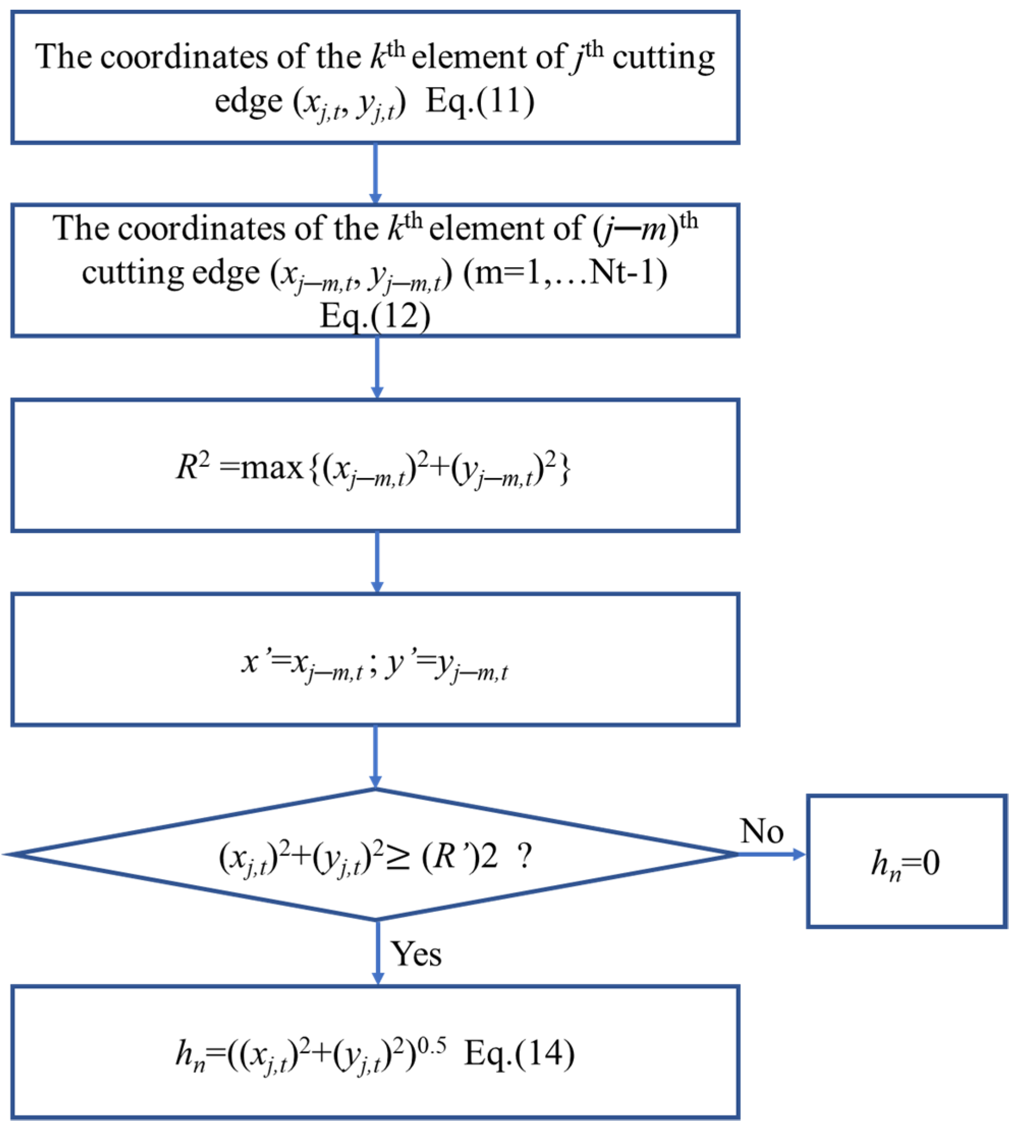
2.2. IUCT Modelling Considering the Tool Runout

Based on the cutting tool edge trajectory modelling above, the IUCT can be obtained. In the micro-milling process, there are three different forms of material removal mechanisms, as shown in Figure 4.
When the IUCT is less than the critical thickness hcr, no chips will be formed, and only elastic deform occurs. Conversely, when the IUCT is greater than the critical thickness, the material is removed by shearing. Additionally, when the IUCT approaches the critical thickness value hcr, elastic and plastic deformation occurs simultaneously. The minimum cutting thickness is determined by the method proposed by Johnson [26] and further supported by the published research results [27].
The IUCT is the distance between the current toolpath and the workpiece surface. As shown in Figure 5, Oi,j1 and Oi,j represent the central positions of the (j1)th and the jth cutting edge trajectory at the height z, respectively. I2 is the intersection point of the straight line Oi,jI1 and the (j1)th cutting edge trajectory. Therefore, the IUCT at φi,j is the distance between point I1 and point I2.
In order to calculate the IUCT, it is necessary to acquire the coordinate values of points I1 and I2. The coordinates of point I1 can be expressed as Equation (11).
[ x I 1 = x O i , j + R sin ( φ i , j ) y I 1 = y O i , j + R cos ( φ i , j )
where x O i , j and y O i , j can be obtained as follows:
x O i , j = f [ t i ( z ) ] + ρ sin ( α + ω t i ( z ) ) y O i , j = ρ cos ( α + ω t i ( z ) )
The coordinate of point I2 is expressed as Equation (12).
[ x I 2 = x O i , j 1 + R sin ( φ i , j 1 ) y I 2 = y O i , j 1 + R cos ( φ i , j 1 )
where x O i , j and y O i , j can be obtained as follows:
x O i , j 1 = f [ t i ( z ) ] + ρ sin ( α + ω t i ( z ) ) y O i , j 1 = ρ cos ( α + ω t i ( z ) )
As the three points Oi, j, I1, and I2 are on the same straight line, their relationship can be expressed as Equation (13).
tan ( φ j [ t i ( z ) ] ) = x I 1 x I 2 y I 1 y I 2
The distance between the points I1 and I2 is the IUCT that only considers the tool runout at any position angle φi,j.
h ρ = [ ( x I 1 x I 2 ) 2 + ( y I 1 y I 2 ) 2 ] 0.5
Based on Equation (12), as long as the value of t i is determined, the coordinate value of point I2 can be obtained. The Newton iteration method is employed to solve Equation (13). Additionally, the initial value of the iteration t i 0 ( z ) is selected as follows:
t i 0 = t i 2 π ω N z
Once t i is obtained, the IUCT that considers the tool runout error can be obtained by Equation (14).
The simulation flowchart for determining the IUCT is shown in Figure 6.
The tool runout error can cause variations in chip thickness, and therefore, some cutting edges may be not engaged in machining. In order to obtain the real IUCT values, the tooth skipping in the cutting process is taken into account.

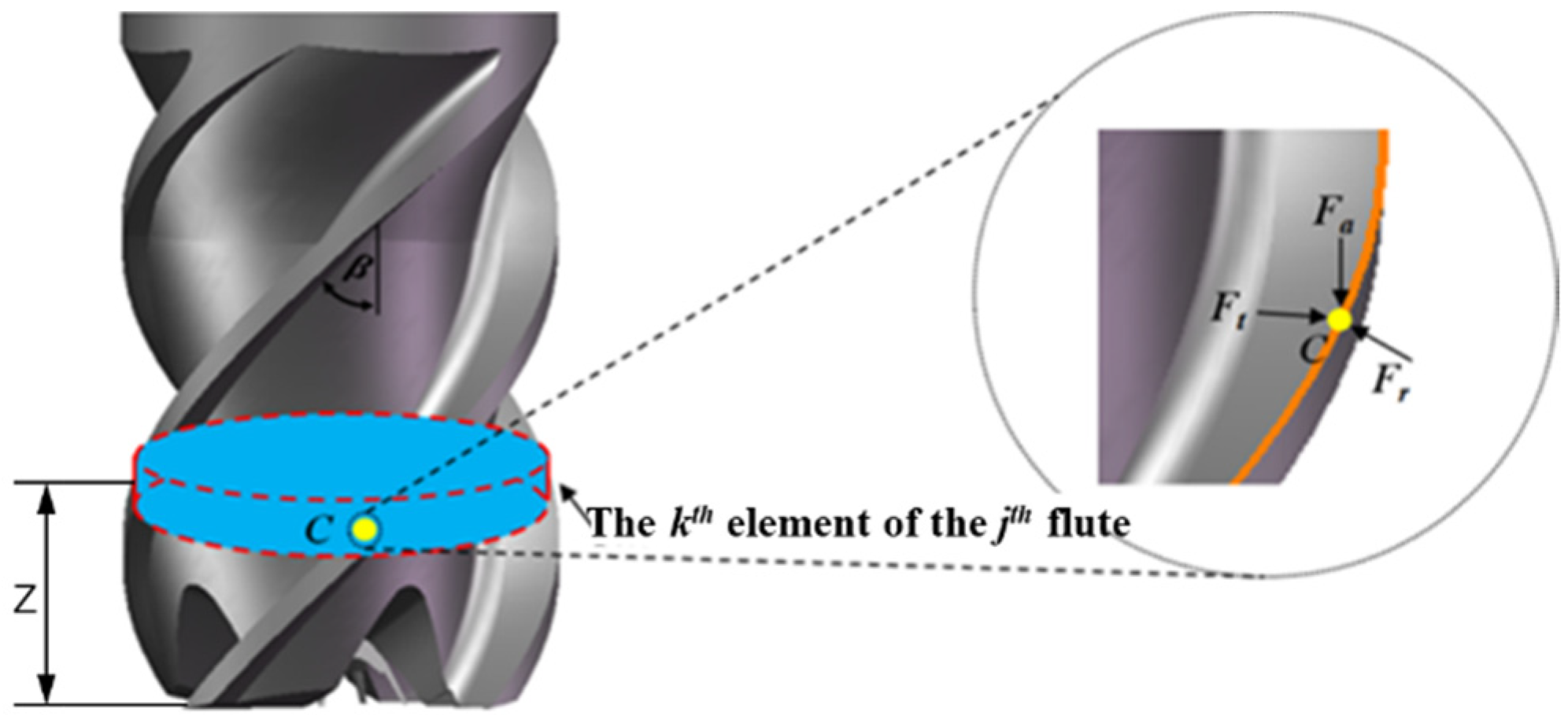
3. Micro-Milling Forces Modelling

As the IUCT is greater than the critical value, the material removal mechanism is the same as that of traditional milling. The tangential, radial, and axial forces acting on different cutter micro-elements during micro-milling are expressed in Equation (16).
{ d F t j [ t i ( z ) ] d F r j [ t i ( z ) ] d F a j [ t i ( z ) ] } = { K t c h j [ t i ( z ) ] + K t e K r c h j [ t i ( z ) ] + K r e K a c h j [ t i ( z ) ] + K a e } d z , ( h j h c r )
The cutting force elements consist of a shear force term and a friction force term, where Kte, Kre, and Kae represent the tangential, radial, and axial cutting-edge coefficients, respectively. Ktc, Krc, and Kac represent the tangential, radial, and axial cutting force coefficients, respectively. hj[ti(z)] is the IUCT, and dz is the height of the micro-element.
The tangential and radial cutting forces elements at the angular position φ can be expressed in Cartesian coordinates as Equation (17).
{ d F x j [ t i ( z ) ] d F y j [ t i ( z ) ] d F z j [ t i ( z ) ] } = [ cos φ sin φ 0 sin φ cos φ 0 0 0 1 ] { d F t j [ t i ( z ) ] d F r j [ t i ( z ) ] d F a j [ t i ( z ) ] }
After integrating the element cutting force, the total cutting force can be obtained.
( F x F y F z ) = j = 1 N t ( d F x j [ t i ( z ) ] d F y j [ t i ( z ) ] d F z j [ t i ( z ) ] )
Due to the low stiffness of the micro-cutting tool and the thin-walled micro-structure, regenerative chatter is unavoidable under the action of periodically milling force, which can cause the change in IUCT, as shown in Figure 7.
Combined with the analysis in Section 2.1, the IUCT considering both the tool runout error and the dynamic regeneration effect can be expressed as Equation (19).
h a = [ ( x I 1 x I 2 + x d ) 2 + ( y I 1 y I 2 + y d ) 2 ] 0.5

4. Validation of the Cutting Forces Modelling

4.1. Cutting Force Experiments and Runout Error Measurement

In order to verify the accuracy of the present micro-milling force model, micro-milling thin-walled experiments were carried out on a Kern five-axis machining centre, as shown in Figure 8.
The positioning accuracy of the Kern Evo machine in x, y, and z directions can reach 0.1 microns, and the spindle speed can reach up to 50,000 rpm. The workpiece was mounted on the dynamometer by means of a fixture. Additionally, its dimensions are illustrated in Figure 8, where W = 1 mm, B = 100 μm, L = 3 mm, and the height of the thin walls ws 600 μm. Table 1 lists the essential tooling parameters of the carbide micro-milling cutters used in experiments; the type of micro-milling tool was SD AFK40.
A Kistler 9256C piezoelectric dynamometer was used to measure the cutting force in x, y, and z directions. It was installed on the machine tool table. The sampling rate for force measurements was 10 kHz. The cutting force data were obtained after processing, as shown in Figure 9.
The cutting-edge radius was measured by scanning electron microscope, as shown in Figure 10. The workpiece materials were Ti-6Al-4V and Al 6061 in test 1 and test 2, respectively. To validate the proposed mechanistic model, the processing parameters used in test 1 and test 2 are shown in Table 2. The cutting parameters were selected according to the stability prediction model; chatter can be avoided using these parameters [28].
The runout error of the cutting tool was measured with a micrometre, as shown in Figure 11. The micrometre was installed on the machine table and rotated manually. During the rotation process, the result was recorded every 45°, the maximum deviation of the results was the tool runout value, and the corresponding direction angle was the runout direction angle, as shown in Figure 12 [6].

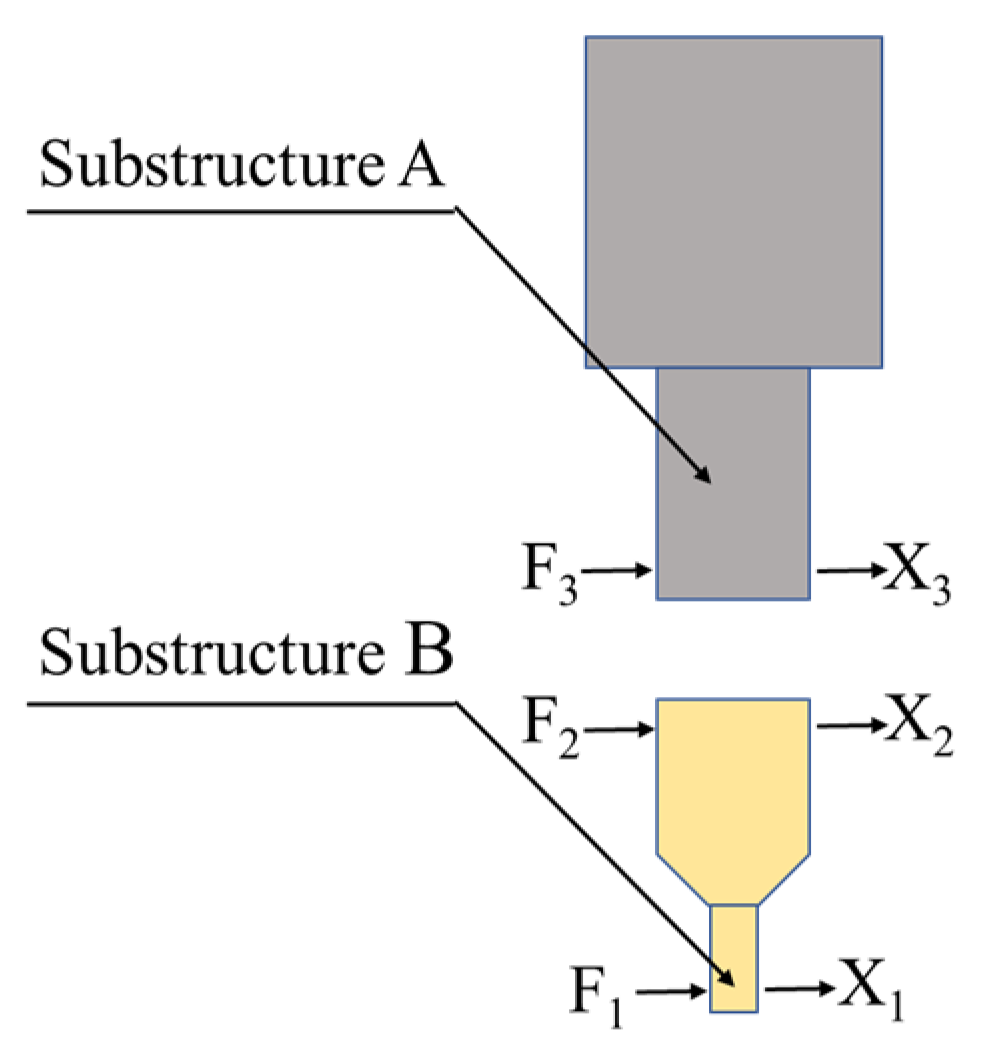
4.2. Identification of Dynamic Parameters

The cutting force model proposed in this paper requires the dynamic parameters of the micro-milling system. Since the micro-milling tool and thin-walled micro-parts are small in size and inconvenient to install sensors, the receptance coupling method was employed to determine the corresponding dynamic parameters.
The response of a structure refers to the relationship between the force exerted on the structure and the deformation of the structure. The receptance coupling method refers to dividing the structure into several substructures; then, the dynamic parameters of each substructure were obtained individually. Finally, the dynamic parameters were assembled. In the micro-milling system, the dynamic parameters of the spindle were obtained by the modal experiment, and the dynamic parameters of the micro-tool and the thin-walled micro-parts were obtained by the finite element method; then, the frequency response function of the machining system could be obtained.
As shown in Figure 13, substructure A is the spindle, and substructure B is the micro-milling cutter.
The transfer function of the whole system can be expressed as Equation (20).
G 11 = X 1 F 1 = H 11 H 12 ( H 22 + H 33 ) 1 H 21
where G and H are the transfer functions of the assembled structure and substructures, respectively [24]. X and F are the deformation and the cutting force, respectively.
In the modal experiment, the Brüel and Kjær 8206-001 impact hammer was used to generate the input excitation signal, and the Brüel and Kjær 4508-B-001 accelerometer was used to gain the output signal. The acquired signals were processed by a dynamic signal analyser, as shown in Figure 14.
The obtained modal parameters in various directions, including natural frequency ωn, stiffness K, and damping coefficients c are listed in Table 3. The subscripts of x and y, t, and w denote the tool and workpiece, respectively.
After obtaining the modal parameters, the transfer function can be expressed as follows:
H ( j ω ) = 1 K ( j ω ) = X ( j ω ) F ( j ω ) = 1 M ω n 2 + j c ω + K
where H denotes transfer function, K denotes dynamic stiffness, F denotes dynamic cutting force, and X denotes dynamic deformation. All the above variables are in the frequency domain.
Moreover, vibration isolation was performed around the machine tool. Therefore, the vibration of other equipment could not be transmitted to the machine tool, and only the vibrations caused by its inner excitation were considered in the article.

4.3. Results and Discussion

The cutting force is periodic in the process of micro-milling. Therefore, only two cycles of the simulation results were selected to compare with the experimental results. The comparison results are shown in Figure 15 and Figure 16. The cutting force model that considered the tool runout error and dynamic deformation error simultaneously is denoted as Model 1, and the cutting force model that only considers the tool runout error is denoted as Model 2, and the cutting force under the ideal condition in which there is no tool runout and chattering is denoted as Model 3. Before the cutting tests, the clamping force acting on the workpiece was measured, while no cutting was performed. It can be seen that the amplitudes of clamping forces in the x, y, and z directions are less than 0.08 N in Figure 17, which is smaller than 4.1% and 5.3% of the cutting forces amplitudes in tests 1 and 2, respectively. Therefore, the influence of the clamping force can be neglected.
It can be observed from the results that the cutting force Model 1 and the cutting force Model 2 are in good agreement with the experimental results in trend. Moreover, it can be concluded that the prediction accuracy of cutting force Model 1 is higher than that of Model 2, which means the dynamics of the machining system has a considerable influence on the cutting force. In addition, at the peaks and troughs of the cutting force, the errors between the predicted values and experimental values are relatively large, which can be caused by tool overhang measurement errors and tool geometry manufacturing errors. Due to the difficulty in identifying the bottom end of the small-diameter tool, the distance from the tool clamping position to the bottom end is difficult to measure, which results in errors during the simulation process. Additionally, the cutting forces at the peaks and troughs are relatively larger. Therefore, the deformation of the cutting tool and workpiece is greater, so are the cutting force errors.
A significant difference is observed between the experimental results and the models at the Fz force. The factors such as noise and random vibration in the micro-milling process have a considerable influence on the z-direction cutting force component due to its small amplitude. Therefore, the measurement signal fluctuates constantly. In comparison, the force signal is significantly attenuated when a low-pass filter is used for noise reduction. It can be seen from the comparison results that the measured force signal and the simulated force signal have good consistency in the overall trend.
Figure 18 shows the root mean square error between the predicted cutting force and the experimental value of test 1. From Figure 18, Model 1 is found to have smaller RMS values in the x, y, and z direction, and resultant force, generally.

5. Conclusions

In this paper, a mechanistic micro-milling forces modeling method was presented, particularly applicable for thin-walled micro-part fabrication. The modelling considers both the influence of the tool runout error and the dynamic regenerative effect. The proposed model was verified by two groups of micro-milling experiments. The cutting force model considering only the influence of the tool runout and the cutting force model under the ideal conditions were also simulated as references. The proposed cutting force model would be helpful for processing precision and machining monitoring in the process of micro-machining thin-walled parts. Based on the obtained results, the following conclusions can be drawn:
(1)
In the micro-milling of thin-walled parts, the actual trajectories of the cutting edge were analysed by considering the tool runout error and the dynamic deformation. On this basis, the instantaneous undeformed chip thickness model was established, which also considers the “tooth skipping” phenomenon.
(2)
Based on the proposed instantaneous undeformed chip thickness model, a mechanistic cutting force model was established. The tool runout errors were measured by a dial indicator. The dynamic parameters of the micro-cutter and thin-walled micro-parts were obtained by the receptance method.
(3)
The micro-milling forces were simulated by MATLAB. Additionally, the proposed model was validated by two groups of dry micro-milling experiments. The results show that the simulated cutting forces are in good consistency with the experimental results. Compared with Model 2 and Model 3, the cutting forces simulated by the proposed method were much closer to the experimental cutting forces. Additionally, the RMS errors of the resultant force between the measured values and the simulated values obtained from the proposed model were all less than 11%. It can be concluded that the cutting forces are significantly influenced by dynamic chatter and tool runout.

Author Contributions

Conceptualisation, P.W. and Q.B.; methodology, P.W.; software, P.W.; validation, Q.B., K.C., L.Z., and H.D.; formal analysis, P.W.; investigation, P.W.; resources, Q.B.; data acquisition, P.W.; writing—original draft preparation, P.W.; writing—review and editing, Q.B. and K.C.; visualisation, P.W.; supervision, Q.B. and K.C.; project administration, Q.B.; funding acquisition, Q.B. All authors have read and agreed to the published version of the manuscript.

Funding

This research work was supported by the National Natural Science Foundation of China (Grant No. 52075129).

Institutional Review Board Statement

Not applicable.

Informed Consent Statement

Not applicable.

Data Availability Statement

The datasets used or analysed during the current study are available from the corresponding author on reasonable request.

Conflicts of Interest

The authors declare no conflict of interest.

References

  1. Gao, X.; Cheng, X.; Ling, S.; Zheng, G.; Li, Y.; Liu, H. Research on optimization of micro-milling process for curved thin wall structure. Precis. Eng. 2022, 73, 296–312. [Google Scholar] [CrossRef]
  2. Li, G.; Wang, F.; Wang, H.; Cheng, J. Microstructure and Mechanical Properties of TC4 Titanium Alloy Subjected to High Static Magnetic Field. Trans Tech. Publ. 2017, 898, 345–354. [Google Scholar] [CrossRef]
  3. Zhang, Y.; Li, S.; Zhu, K. Generic instantaneous force modeling and comprehensive real engagement identification in micro-milling. Int. J. Mech. Sci. 2022, 176, 105504. [Google Scholar] [CrossRef]
  4. Lee, H.U.; Cho, D.; Ehmann, K.F. A Mechanistic model of cutting forces in micro-end-milling with cutting-condition-independent cutting force coefficients. ASME J. Manuf. Sci. Eng. 2008, 3, 031102. [Google Scholar] [CrossRef]
  5. Bao, W.Y.; Tansel, I.N. Modeling micro-end-milling operations. Part I: Analytical cutting force model. International Journal of Machine Tools and Manufacture. Int. J. Mach. Tools Manuf. 2000, 40, 2155–2173. [Google Scholar] [CrossRef]
  6. Zhang, X.; Ehmann, K.F.; Yu, T.; Wang, W. Cutting forces in micro-end-milling processes. Int. J. Mach. Tools Manuf. 2016, 107, 21–40. [Google Scholar] [CrossRef]
  7. Sahoo, P.; Patra, K. Mechanistic modeling of cutting forces in micro-end-milling considering tool run out, minimum chip thickness and tooth overlapping effects. Mach. Sci. Technol. 2018, 23, 407–430. [Google Scholar] [CrossRef]
  8. Jing, X.; Tian, Y.; Yuan, Y.; Wang, F. A runout measuring method using modeling and simulation cutting force in micro end-milling. Int. J. Adv. Manuf. Technol. 2017, 91, 4191–4201. [Google Scholar] [CrossRef]
  9. Li, G.; Li, S.; Zhu, K. Micro-milling force modeling with tool wear and runout effect by spatial analytic geometry. Int. J. Adv. Manuf. Technol. 2020, 107, 631–643. [Google Scholar] [CrossRef]
  10. Afazov, S.M.; Ratchev, S.M.; Segal, J. Modelling and simulation of micro-milling cutting forces. J. Mater. Processing Technol. 2010, 210, 2154–2162. [Google Scholar] [CrossRef]
  11. Rodríguez, P.; Labarga, J.E. A new model for the prediction of cutting forces in micro-end-milling operations. J. Mater. Processing Technol. 2013, 213, 261–268. [Google Scholar] [CrossRef]
  12. Li, K.; Zhu, K.; Mei, T. A generic IUCT model for the cutting force modeling in micromilling. Int. J. Mach. Tools Manuf. 2016, 105, 23–31. [Google Scholar] [CrossRef]
  13. Liu, K.; Melkote, S.N. Finite element analysis of the influence of tool edge radius on size effect in orthogonal micro-cutting process. Int. J. Mech. Sci. 2007, 49, 650–660. [Google Scholar] [CrossRef]
  14. Varghese, A.; Kulkarni, V.; Joshi, S.S. Modeling cutting edge degradation by chipping in micro-milling. Wear 2022, 488–489, 204141. [Google Scholar] [CrossRef]
  15. Lucca, D.A.; Rhorer, R.L.; Komanduri, R. Energy Dissipation in the Ultraprecision Machining of Copper. CIRP Ann. 1991, 40, 69–72. [Google Scholar] [CrossRef]
  16. Lai, X.; Li, H.; Li, C.; Lin, Z.; Ni, J. Modelling and analysis of micro scale milling considering size effect, micro cutter edge radius and minimum chip thickness. Int. J. Mach. Tools Manuf. 2008, 48, 1–14. [Google Scholar] [CrossRef]
  17. Sun, Z.; Zhang, T.; Li, P.; Wang, S.; To, S.; Wang, H. Analytical modelling of the trans-scale cutting forces in diamond cutting of polycrystalline metals considering material microstructure and size effect. Int. J. Mech. Sci. 2021, 204, 106575. [Google Scholar] [CrossRef]
  18. Wang, W.; Zhang, W.; Huang, D.; Wang, W. Cutting force modeling and experimental validation for micro end milling. Int. J. Adv. Manuf. Technol. 2021, 117, 933–947. [Google Scholar] [CrossRef]
  19. Malekian, M.; Park, S.S.; Jun, M.B.G. Modeling of dynamic micro-milling cutting forces. Int. J. Mach. Tools Manuf. 2009, 49, 586–598. [Google Scholar] [CrossRef]
  20. Chen, W.; Teng, X.; Huo, D.; Wang, Q. An improved cutting force model for micro milling considering machining dynamics. Int. J. Adv. Manuf. Technol. 2017, 93, 3005–3016. [Google Scholar] [CrossRef] [Green Version]
  21. Afazov, S.M.; Ratchev, S.M.; Segal, J.; Popov, A.A. Chatter modelling in micro-milling by considering process nonlinearities. Int. J. Mach. Tools Manuf. 2012, 56, 28–38. [Google Scholar] [CrossRef] [Green Version]
  22. Shi, J.; Jin, X.; Cao, H. Chatter stability analysis in Micro-milling with aerostatic spindle considering speed effect. Mech. Syst. Signal Processing 2022, 169, 108620. [Google Scholar] [CrossRef]
  23. Cao, Z.; Li, H. Investigation of machining stability in micro milling considering the parameter uncertainty. Adv. Mech. Eng. 2015, 7. [Google Scholar] [CrossRef]
  24. Mascardelli, B.A.; Park, S.S.; Freiheit, T. Substructure Coupling of Micro End Mills. In Proceedings of the ASME International Mechanical Engineering Congress and Exposition, IMECE2006, Chicago, IL, USA, 5–10 November 2006. [Google Scholar]
  25. Kanh, M. Modeling of Cutting Forces in Micro Milling Including Run-Out. Master’s Thesis, Bilkent University, Ankara, Turkey, 2014. [Google Scholar]
  26. Johnson, K.L. Contact Mechanics; Cambridge University Press: Cambridge, UK, 1985. [Google Scholar]
  27. Niu, Z.; Jiao, F.; Cheng, K. An innovative investigation on chip formation mechanisms in micro-milling using natural diamond and tungsten carbide tools. J. Manuf. Processes 2018, 31, 382–394. [Google Scholar] [CrossRef]
  28. Zhang, X.; Yu, T.; Wang, W. Chatter stability of micro end milling by considering process nonlinearities and process damping. Int. J. Adv. Manuf. Technol. 2016, 87, 2785–2796. [Google Scholar] [CrossRef]
Figure 1. Flowchart of micro-milling forces modelling.
Machines 10 00217 g001
Figure 2. Cutting force acting on the cutter micro-element.
Machines 10 00217 g002
Figure 3. Runout error of cutting tool: (a) side view of runout error; (b) top view of runout error.
Machines 10 00217 g003
Figure 4. Material removal mechanism in micro-milling.
Machines 10 00217 g004
Figure 5. Trajectory of the (j1)th and jth cutting edge.
Machines 10 00217 g005
Figure 6. Flowchart for calculating the IUCT.
Machines 10 00217 g006
Figure 7. Regenerative chatter in micro-milling.
Machines 10 00217 g007
Figure 8. Illustration of the micro-milling experiments.
Machines 10 00217 g008
Figure 9. Analysis system of cutting forces.
Machines 10 00217 g009
Figure 10. The micro-milling tool and its cutting-edge radius: (a) micro-cutter 1; (b) micro-cutter 2.
Machines 10 00217 g010
Figure 11. Tool runout measurement.
Machines 10 00217 g011
Figure 12. Runout measurement results.
Machines 10 00217 g012
Figure 13. Substructure of receptance coupling method.
Machines 10 00217 g013
Figure 14. Modal analysis and experiments.
Machines 10 00217 g014
Figure 15. Comparison of the simulated and experimental force results of test 1: (a) simulated and experimentally determined cutting forces in x direction; (b) simulated and experimentally determined cutting forces in y direction; (c) simulated and experimentally determined cutting forces in z direction.
Machines 10 00217 g015
Figure 16. Comparison of the simulated and experimental force results of test 2: (a) simulated and experimentally determined cutting forces in x direction; (b) simulated and experimentally determined cutting forces in y direction; (c) simulated and experimentally determined cutting forces in the z direction.
Machines 10 00217 g016
Figure 17. The clamping force acting on the workpiece.
Machines 10 00217 g017
Figure 18. RMS of simulated cutting force in test 1: (a) RMS of simulated cutting force in x direction; (b) RMS of simulated cutting force in y direction; (c) RMS of simulated cutting force in z direction; (d) RMS of simulated resultant cutting force.
Machines 10 00217 g018
Table 1. Material and parameters of the micro-milling cutter.
Cutter 1Cutter 2
MaterialCarbideCarbide
Helix angle 45°45°
Edge diameter1 mm0.6 mm
Tool length20.5 mm20.5 mm
Edge radius1.9 μm2.0 μm
Teeth number42
Table 2. Cutting parameters of the validation experiments.
n (r/mim)ae (μm)ap (μm)fz (μm/Tooth)
10,0001000505
25,000600205
Table 3. Modal parameters of the spindle and cutter system.
Directionωn (Hz)K (N/μm)M (Kg)c (%)
xt250050.150.8
yt250050.151.1
xw1500210.21
yw43001400.20.7
Publisher’s Note: MDPI stays neutral with regard to jurisdictional claims in published maps and institutional affiliations.

