Article

Assist-As-Needed Control Strategy of Bilateral Upper Limb Rehabilitation Robot Based on GMM

1
School of Mechanical Engineering, Taiyuan University of Science and Technology, Taiyuan 030024, China
2
Cixi Institute of BioMedical Engineering, Ningbo Institute of Materials Technology and Engineering, Chinese Academy of Sciences, Cixi 315300, China
3
Ningbo Institute of Materials Technology and Engineering, Chinese Academy of Sciences, Ningbo 315201, China
*
Authors to whom correspondence should be addressed.
Machines 2022, 10(2), 76; https://doi.org/10.3390/machines10020076
Submission received: 3 December 2021 / Revised: 7 January 2022 / Accepted: 10 January 2022 / Published: 21 January 2022
(This article belongs to the Topic Motion Planning and Control for Robotics)

Abstract

:
Robotic-assisted rehabilitation therapy has been shown to be effective in improving upper limb motor function and the daily behavior of patients with motor dysfunction. At present, the majority of upper limb rehabilitation robots can only move in the two-dimensional plane, and cannot adjust the assistance mode in real-time according to the patient’s rehabilitation needs. In this paper, according to the shortcomings of the current rehabilitation robot only moving in the two-dimensional plane, a type of bilateral mirror upper limb rehabilitation robot structure with the healthy side assisting the affected side is proposed. This can move in three-dimensional space. Additionally, an assist-as-needed (AAN) control strategy for upper limb rehabilitation training is proposed based on the bilateral upper limb rehabilitation robot. The control strategy adopts Gaussian Mixture Model (GMM) and impedance controller to maximize the patient’s rehabilitation effect. In the task’s design, there is no need to rely on the assistance of the therapist, only the patients who completed the task independently. GMM guides the rehabilitation robot to provide different assistance for the patients at different task stages and induces the patients to complete the rehabilitation training independently by judging the extent to which the patients can complete the task. Furthermore, in this paper, the effectiveness of the proposed control strategy was verified by three volunteers participating in a two-dimensional task. The experimental results show that the proposed AAN control strategy can effectively provide appropriate assistance according to the classification stage of the interaction between the patients and the rehabilitation robot, and thus, patients can better achieve the rehabilitation effect during the rehabilitation task as much as possible.

1. Introduction

According to the 2019 global health estimate report [1], stroke is the second leading cause of death in humans. As a result of stroke, most patients’ limbs have different degrees of motor dysfunction. According to the theory of plasticity in the brain, a certain number of functional reorganizations of rehabilitation, combined with effective rehabilitation control strategies, can restore limb movement function [2,3]. Clinical studies have shown [4] that rehabilitation robots can effectively improve the motor function of the patient’s limb, and even restore daily life movements.
For patients with motor dysfunction, the rehabilitation process mainly repeats a movement for a long time, in order to strengthen the movement function of the damaged parts of the body. However, continuing the same movement for a long time is exhausting, and may make the patients produce negative attitudes, leading to a decrease in the level of attention, and thus a reduction in the effectiveness of rehabilitation therapy [5]. How to promote patients’ active participation and improve their attention [6] has become a hot topic in the field of neural rehabilitation research [7].
One of the most critical research areas of rehabilitation robotics is the development of control strategies that can regulate physical interaction with patients to facilitate patient neuroplasticity so that patients with muscle weakness caused by nerve injury can improve or recover movement [8]. Rehabilitation robots can provide repeatable and function orientation training, an important factor to enhance nervous system restoration. This plays a significant effect in the treatment process, but [6] suggests that the rehabilitation robot consistently interacts with patients in a passive motor manner, with no significant improvement in the later stages of stroke patients. This suggests that improving patient motor recovery requires active patient involvement. For patients with partial movement ability, the minimum assistance controller strategy has proved to have more effective results through active assistance movement, providing patients with a minimum assistance controller. This is called an “assist-as-needed” (AAN) controller [8,9], and is usually operated by a force field control or impedance control based on the position error to achieve [9]. Nonetheless, ANN’s disadvantage is that it cannot tell what position the patient is currently in, and it is easy to provide assistance when the patient does not need assistance, leading to the patient’s state of slackness.
The AAN controller is adjusted according to the limb’s ability to then adjust the intervention of the assistance, and different techniques have been used to identify the patient’s remaining ability to input this into the control strategies. In the paper [10], before controlling the robot, muscle electromyography signals are used to estimate the subjects’ torque and then used as an input to the controller. However, because electromyography signal processing has some difficulties, electromyography signals are most effective when used to trigger specific actions. In the paper [5,7], electroencephalogram signals are used to identify the patient’s intent, and through the analysis of electroencephalogram signals, the human thinking mechanism can be obtained to monitor in real-time the state of the patients, which can further adjust the training strategy, so as to improve the patient’s attention and speed up the recovery. Nonetheless, the electroencephalogram is vulnerable to the interference of environmental factors. Moreover, the attendance requirement of the subjects is relatively high. At present, physical information during human-computer interaction is commonly used to estimate the subject torque, such as force sensor information [11] and position information [12,13] to estimate the input of the subjects or physical information in different motion states of robot interaction with the external environment to design different stability control strategies in stages [14]. However, the force sensor needs to select the maximum, minimum and average value of force information combined with EMG information as the mechanical signal characteristics and location information needs to be assisted by visual display, along with tracking error adjustment for patients, so the input estimation of subjects by the controller designed above cannot express the intention of subjects.
Technologies, such as machine learning, artificial neural networks, and fuzzy logic systems have been considered as feasible technologies for developing adaptive control systems. In order to solve the shortcomings of the current AAN control strategy, this paper implements the AAN control strategy based on the Gaussian Mixture Model (GMM), an AAN controller that changes the control strategy according to the degree of task completion by patients, will be proposed. By learning and calculating the interaction information between the patients and the robot, the corresponding assist strategy is designed.
GMM is a type of probability density function that requires less data to obtain good results and does not require any prior knowledge, compared with other commonly used techniques, such as a neural network [15] providing faster regression [16], which is widely used in data modeling. The model can parameterize a set of data points and its underlying functions into a weighted sum of the Gaussian component density, each of which has its own mean and covariance. Due to the simplicity of Gaussian functions, strong adaptability and the advantages of generative modeling, GMM has been widely used in robot demonstration learning (LFD) [17,18,19].
In order to prove the effectiveness of the proposed control strategy, we carried out experiments on the developed end-effector upper limb mirror rehabilitation robot, and the relevant contributions are as follows:
(a)
In order to restore the upper limbs of patients with motor dysfunction, we developed a new end-effector upper limb mirror rehabilitation robot. Patients can use the robot’s arm to provide rehabilitation trajectory for the patient’s impaired limb (PIL), making patients have the maximum freedom with the rehabilitation trajectory, meanwhile, the movement trajectory of the robot’s side mechanical arm can more accurately reflect the patient’s movement intention.
(b)
The AAN control strategy based on GMM was developed. The strategy can determine the stage at which the patients need assistance depending on how much the patients complete the task each time, and give appropriate assistance in the next task. If it appears in the process that the patients in rehabilitation are not comfortable, we can at any time change the PIL trajectory using the patient’s functional limb (PFL), and prevent secondary damage to patients, to achieve the best results of rehabilitation.
(c)
We specifically verified the proposed control strategy method to evaluate the participants’ ability to participate in the task, and used EMG signals to obtain the activation degree of the subjects’ muscles during the task, and verified the effectiveness of the AAN control strategy based on GMM for rehabilitation through the study of the subjects.

2. Materials and Methods

2.1. Overall Design of the Mirror Upper Limb Rehabilitation Robot

Aiming at patients with upper limb motor dysfunction, this paper developed a type of end-effector bilateral mirror upper limb rehabilitation robot device, which has three degrees of freedom and can guide patients’ arms to carry out rehabilitation training in a three-dimensional space trajectory (Figure 1).
The mirror upper limb rehabilitation robot designed in this paper is mainly composed of a healthy side manipulator, affected side manipulator, and rotary mechanism. The affected side manipulator is driven by three motors with a force sensor at the end of the affected side manipulator, and the healthy side manipulator is driven directly by the PFL. In order to facilitate the calculation of the end position of the healthy side manipulator, the three angle sensors are installed at its three joints (Figure 1). The manipulators on both sides are designed based on anthropometric theory [20,21], which can drive the shoulder and elbow joints of the human body.
Because the rehabilitation robot design object is different for hemiplegia patients, according to the patient’s stroke position (right or left upper limbs), the rotary mechanism and bilateral mechanical arm can make the corresponding rotation adjustment, and the distance between the base is adjustable and suitable for different patients with shoulder breadth. In addition, in order to facilitate people of different heights, the location of the seats can be adjusted freely. Considering the connection and comfort between the patient’s hand and the end of the robot, retractable trays and straps are specially designed to suit the patients. The display screen is placed on the opposite side for the patients to facilitate, which is convenient for the patients to interact with the designed virtual scene and can enhance the rehabilitation effect of the patients.

2.2. Kinematics and Dynamics Modeling of the Mirror Upper Limb Rehabilitation Robot

As shown in Figure 1, in the process of rehabilitation training, the structures of both robotic arms are symmetric, so only one side of the robot needs to be modeled. The forward kinematics analysis in this paper mainly studies the conversion relationship between the relative coordinate system of the handle and the world coordinate system. The origin of the world coordinate system of the rehabilitation robot is set at joint 1 of the manipulator (as shown in Figure 2). According to the DH parameter method, the coordinates and DH parameters of the manipulator’s connecting rod are shown in Figure 2 and Table 1, respectively. The transformation matrix of the handle coordinate system in the world coordinate system is shown in Equations (1) and (2).
T i W = T 0 W T i 1 0 T i i 1 = n x o x a x p x n y o y a y p y n z o z a z p z 0 0 0 1
T i 0 = i = 1 i T i i 1 q i
where q is the joint position, n , o , a and P are the direction matrix and position vector of the end of the manipulator in the world coordinate system, respectively.
The dynamics of the combination of a mirror rehabilitation robot and the human body can be expressed by Equation (3)
M q q ¨ + C q , q ˙ q ˙ + G q + F q ˙ = τ + J T q F s
where q , q ˙ , q ¨ R respectively on behalf of the angle, angular velocity and angular acceleration of the mechanical arm joints, M q R n × n is the inertia matrix, C q , q ˙ R n × n denotes the centrifugal and Coriolis matrix, G q R n is the gravity vector, F q ˙ R n denotes the friction vector, τ R n denotes the vector of robot joint torque, J q is the Jacobian matrix, and the F s is the external force vector exerted by the user on the end of the robot. It is measured by the robot terminal force sensor.
Many robot control methods can be realized based on the robot dynamics model, such as position control, torque control and impedance control, among which impedance control is a classical control method [22]. In rehabilitation assistance, the method of trajectory tracking combined with impedance control can be used to help patients perform the required tasks, and the assistance force can be changed according to the rehabilitation process and the patient’s situation and degree of participation. In the mirror rehabilitation strategy proposed in this paper, the expected reference impedance model defined for the mirror rehabilitation robot system is that the trajectory of the PFL is taken as the input of the system, and then the rehabilitation robot uses its position tracking controller to respond and track. To facilitate expression, impedance control of the mirror rehabilitation system in Cartesian space can be expressed as:
M d e s x ¨ d e s x ¨ t a r + B d e s x ˙ d e s x ˙ t a r + K d e s x d e s x t a r = F F s
where x d e s is the trajectory of the PFL as the expected trajectory, x t a r is the actual position trajectory of the PIL; M, B and K are the virtual mass coefficient matrix, virtual damping coefficient matrix and virtual stiffness coefficient matrix required by the reference impedance model, respectively, F is the force exerted by the end-effector of the manipulator, and F s is the external force exerted by the user on the end of the robot. In order to have different impedance characteristics in different directions of the motion space, the above parameters can be replaced by matrices. The control goal of the rehabilitation robot is to track the response of the impedance model, that is x t a r to x d e s . Once the PIL deviates from the target position of the PFL, the controller will apply assistance force to the robot arm.
With upper limb motor dysfunction in the prophase and metaphase stages of rehabilitation there is usually no activity, or only part of the activity ability—the upper limb muscles cannot fully support upper limb rehabilitation training tasks. Patients who have activities of consciousness, but cannot complete the training task alone, to a large extent, hindered the recovery of upper limb movement function [23]. Therefore, when patients are unable to complete rehabilitation training tasks, rehabilitation robots are needed to assist patients with completing these training tasks. In general, in rehabilitation training, a patient’s upper limb speed is relatively slow. Studies have shown that slow training is more beneficial to the recovery of upper limb movement than fast training [24], so in rehabilitation training, sports location is more important than speed in patients [22]. According to the impedance control Equation (4), assistance force and the deviation of the relationship between the end of the robot can be simplified as:
K ( x d e s x t a r ) = F a s s i s t

2.3. Gaussian Mixture Model

The Gaussian Mixture Model (GMM) is used to accurately quantify things using the Gaussian probability density function. The data can be classified into several models based on the Gaussian probability density function and trained using the expectation-maximization (EM) algorithm. Compared with other classification models, GMM can give the probability of a sample for all categories. Therefore, GMM can not only be used for classification, but also for the estimation of probability density, which can simulate the variability of performing tasks in various experiments. In most cases, capturing a sequence of human movements requires multiple Gaussian values to model the task, which is why GMM is used [25].

2.4. AAN Control Strategy Based on GMM

During a stroke patient’s recovery, spasms occur [26] and the muscle tone will increase at this time. In order to alleviate the patient’s muscle tension, we need to assist the patient’s limb stretching. Hence, this paper designed a circle task, and with a long time of rehabilitation training, the patients easily produced fatigue or slack from negative emotions, reduced their willingness to recover, and affected the positive effect of rehabilitation. Nonetheless, in order to focus the patient’s attention and improve active participation, this paper proposes an AAN control strategy based on GMM, which can, according to the current position of the PIL of the patients, allow for the rehabilitation task stage of the patients to be judged, so as to give appropriate assistance according to the different task stages of the patients.
First, N points were uniformly sampled from the affected side of the mechanical arm trajectories and force sensor of the rehabilitation robot to construct the data set of GMM classification:
X = x i , y i , Fx i , Fy i R n N i = 1
where x i ,   y i represents the coordinates of the i th point at the end of the manipulator in Cartesian space, Fx i ,   Fy i represents the value of the force sensor at the corresponding coordinates of the end of the manipulator, and X represents the collected data set.
GMM can be expressed as follows:
p X = i = 1 K π i N ( X | μ i , i )
N ( X | μ i , i ) = 1 ( 2 π ) p + q + 1 i e 1 2 X μ i Τ i 1 X μ i
Equation (8) shows multiple (p + q + 1) dimensional gaussian probability density function (PDF); the parameters in Equation (7) also include prior weight π i , mean value μ i and covariance matrix i , among which N ( x | μ i , i ) is the K th component in the mixed model. In this paper, two classification stages are designed to be represented by Gaussian distribution, namely, the active recovery stage and the passive recovery stage, thus K = 2 , π i is prior weight and meets the requirements.
i = 1 K π i = 1 , i : 0 π i 1
Finally, the expectation-maximization (EM) algorithm [27] is used to train the mixed model.
Figure 3 is the control strategy block diagram design based on the GMM algorithm, in which GMM is used to classify task X completed to obtain the active and passive rehabilitation stage. When patients performed the task again, we determined the classification region of the phase in which the current position is located and modified the stiffness coefficient K using Equation (5) to adjust the assistance force. If in the area of active recovery, the PIL position of the patients does not provide assistance even if it is far from the PFL position; if in the area of passive recovery, according to the design of the position tracking controller Equations (10) and (11), the controller will provide assistance force according to the difference between the patient’s PIL position and PFL position, to complete the rehabilitation task.
K = K min + ( K max 1 K min ) φ
φ = e e min e max e min
where K m a x and K m i n are the maximum and minimum values of virtual stiffness respectively, e m a x and e m i n are the maximum and minimum values of the specified error range respectively, the maximum and minimum of K and e can be adjusted according to the needs of the patient’s rehabilitation training task. Therefore, by adjusting the maximum and minimum value, different assistance force fields can be constructed; the e is the error between the coordinates on both sides of the mechanical arm.
When the rehabilitation robot switches from the active recovery position to the passive recovery position, K value suddenly changes, leading to assistance force mutations. This kind of circumstance is not safe for the patients, hence, the need to design a type of transition function. The K value can be slow to transition between the two different states. This paper uses the minimum jerkiness trajectory [28] to design a transition function. This theory is applied to wrist rehabilitation training to produce as smooth hand movement as possible [29]. Based on the minimum jerky trajectory, this paper designs an Equation (12) suitable for the slow transition of K value.
K t = K min + K 2 K min × 10 t T 3 15 t T 4 + 6 t T 5
where K min is the value set at the active recovery position, K 2 is the value calculated at the passive recovery position, K(t) is the actual value, T is the total transition time set at 1 s, and t is the current time.

3. Experiment

3.1. The Subjects

In this paper, the study involved three healthy male subjects (mean age of 25, mean height of 175 cm) with no known neurological impairment. All procedures were carried out in accordance with the standards set out in the Declaration of Helsinki for medical research involving humans, and the study was approved by the local medical ethics committee.

3.2. Rehabilitation Robot Experimental Platform

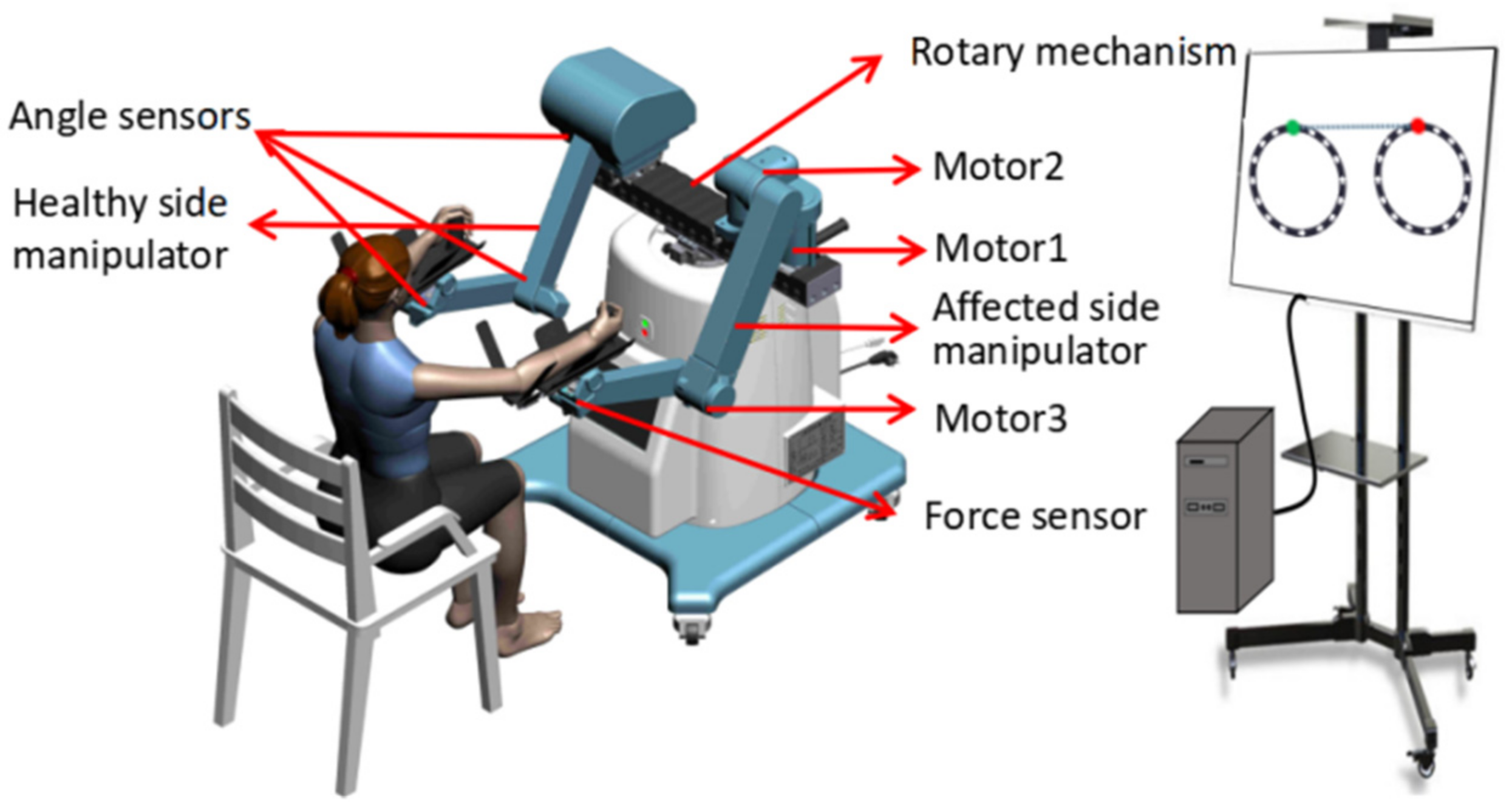
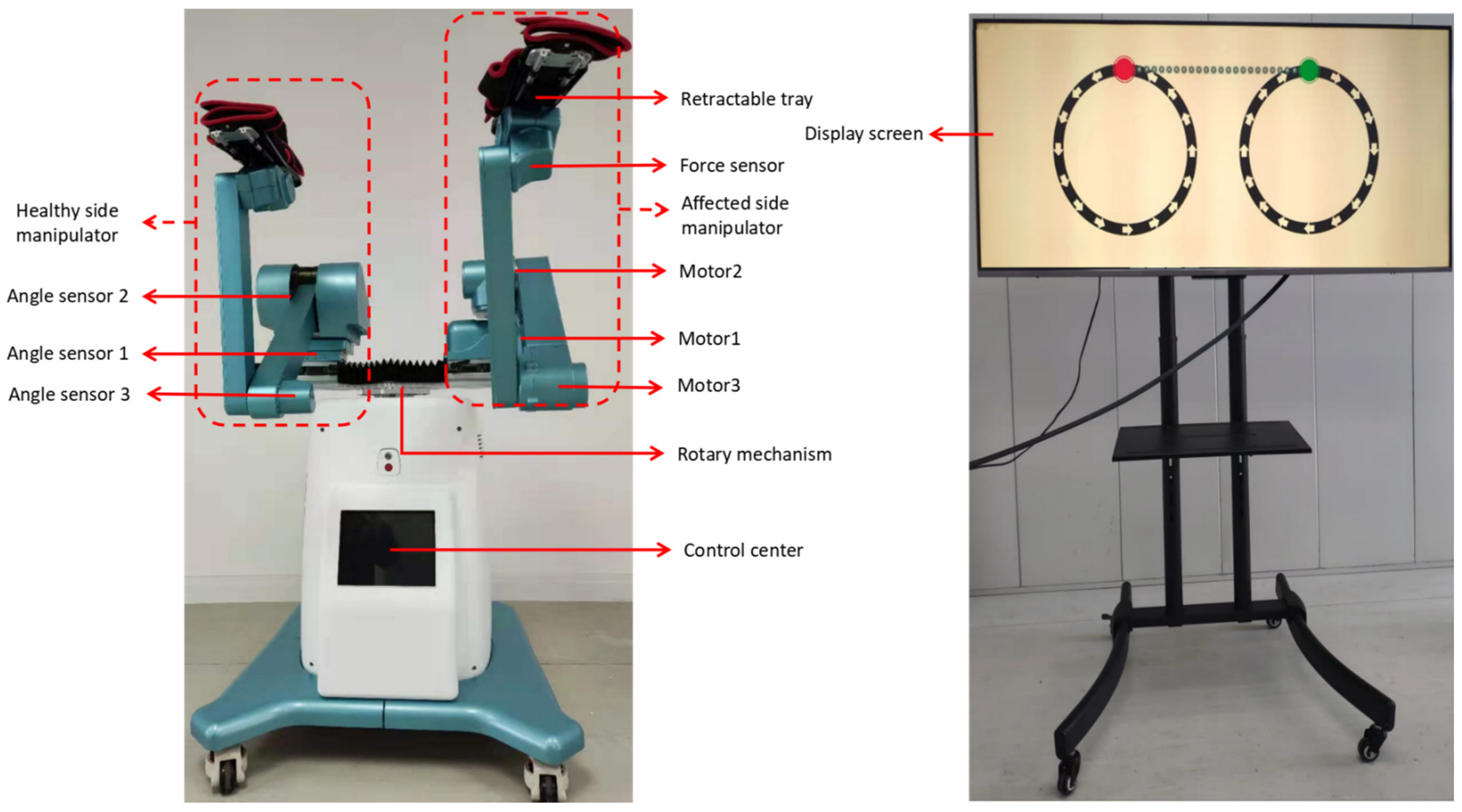
In this study, a self-designed end-effector bilateral mirror upper limb rehabilitation robot device was used. The rehabilitation robot has two mechanical arms, one is a mechanical structure, and the internal spring is helpful for the flexible movement of the mechanical arm, which interacts with the volunteer’s PFL; the other side of the robot arm contains three motors to drive the volunteer’s PIL movement, which interacts with the volunteer’s PIL to help patients achieve spatial rehabilitation tasks (Figure 4). During the experiment, volunteers sat directly opposite the rehabilitation robot. The virtual environment used in the experiment (Figure 5) was developed by Unity. The volunteer’s right arm mimicked the PIL and their left arm mimicked the PFL.
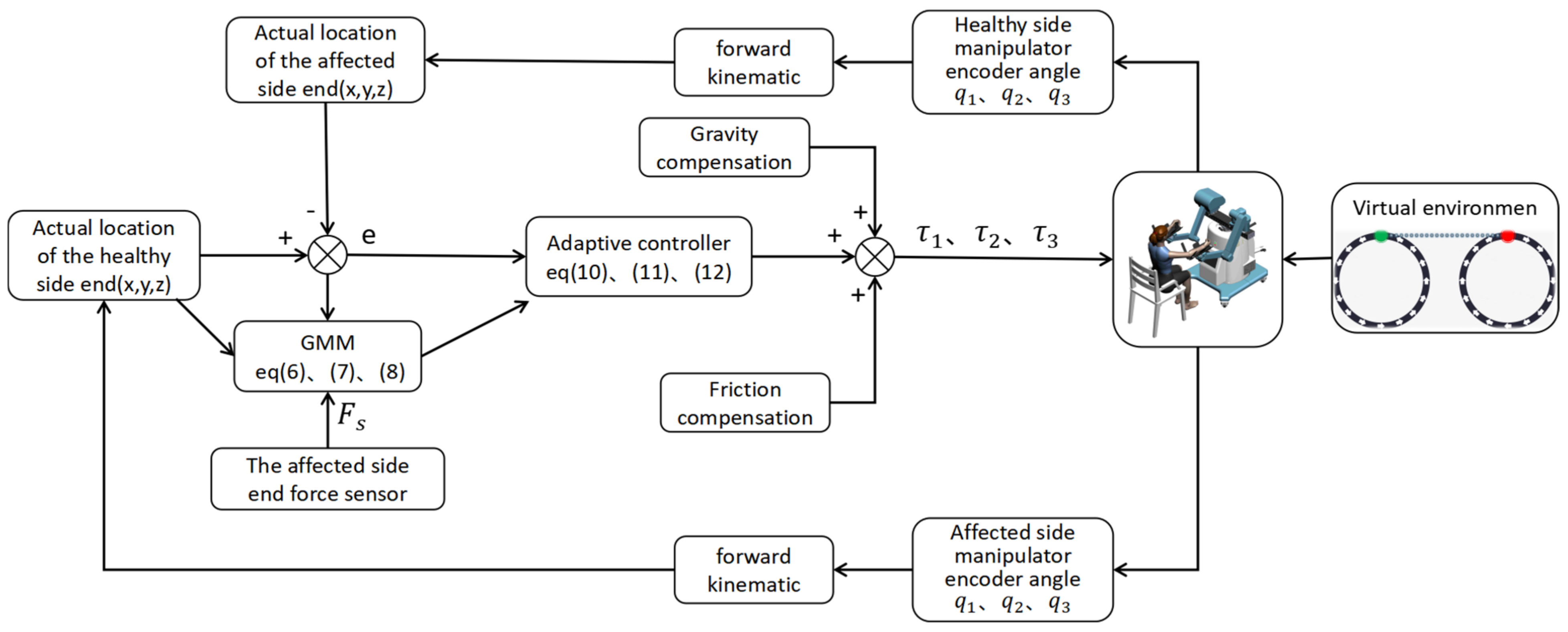
In order to verify the mechanism design and control strategy of the rehabilitation robot designed in this paper, the electrical system and human-computer interaction interface of the robot are also designed. Figure 5 is the block diagram of the electrical system of the rehabilitation robot, which mainly includes the control center module, human-computer interaction module, data processing module, and data acquisition module.
The core function of the control center module is to run the control program, carry out TCP/IP communication with the human-computer interaction module and the data processing module, transmit the physical information needed, and carry out EtherCAT communication with the data acquisition module, accept and send operation instructions, and realize the coordinated control of the robot. The human-computer interaction module communicates with the control center, which is mainly used for doctors to set the rehabilitation parameters of patients, and displays the current position of the end of the robot on the main interface, using visual feedback to interact with patients. Through communication with the control center, the data acquisition module mainly collects signals from motor encoders, force sensors and angle sensors to identify the patient’s current position and motion intention, and read the rotation angle and angular velocity of motion. The data processing module communicates with the control center, mainly carries on the down-sampling processing to the collected physical signals, and then uses the GMM algorithm to process and transmit the necessary information to the control center.
Stretching exercises are usually part of rehabilitation exercises. For simplicity, this training task is designed to draw a circle in a two-dimensional cartesian plane with the starting coordinates of (0.4, 0, 0) m, the center coordinates of (0.5, 0, 0) m, and the radius of 0.1 m (Figure 6). Studies have shown that slow training can improve the recovery of upper limb movement more than fast training, so the virtual mass parameter is set as M = 0 and the virtual damping coefficient is set as B = 0.

3.3. EMG Signals Are Used to Verify the Effectiveness of the GMM Algorithm

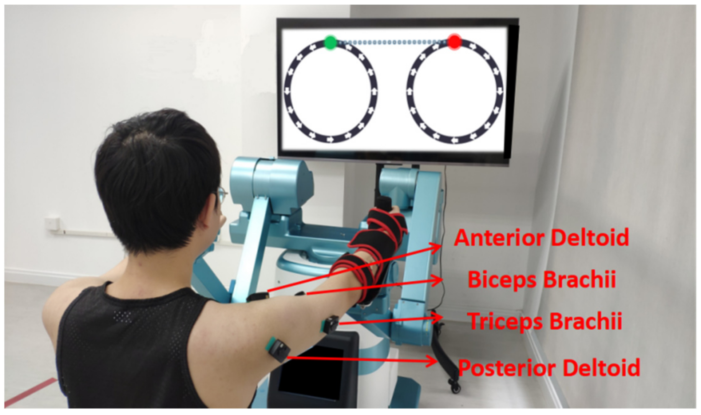
The experiment was carried out by a healthy volunteer aged 25 years and measured 175 cm tall. During the experiment, the volunteer sat opposite the rehabilitation robot and placed a screen in front of it to display the designed virtual environment, and visually induced the volunteer to do tasks (Figure 7).
In the experiment, the DelsysTrigno device was used to collect EMG signals, and the sampling rate was 1927 Hz. The control period of the rehabilitation robot system was 1 ms. During the interaction between the volunteer and the rehabilitation robot, the position information and force sensor information of the affected side of the robot arm were collected, and the emG signals of the volunteer’s biceps brachii, triceps brachii, anterior deltoid and posterior deltoid muscles were collected at the corresponding time.
This experiment asked the volunteer to achieve the two different states in the two groups of experiments. In the first group of experiments, the volunteer was asked to simulate the state of a healthy person to interact with the robot; in the second group of experiments, the volunteer was asked to simulate the state of a patient to interact with the robot. The initial position was set in the distal circle, as shown in Figure 6. The volunteer adjusted their state according to the terminal real-time trajectory displayed on the screen, and the speed should not be too fast. Each group of experiments carried out five circle drawing tasks. When the GMM algorithm is used for classification, the size of data will affect the processing speed, so the sampling rate in the system is reduced to 20 Hz to improve the processing efficiency.
As the time for the volunteer to complete the task could not be guaranteed during the experiment, there was no periodic correspondence between the EMG signals of the two states in Figure 8. As can be seen from Figure 8, the EMG signal values of the simulated patient are generally higher than that of the healthy subject, which is due to the presence of the volunteer’s simulated muscle tension. The anterior deltoid and the posterior deltoid muscles in the two states of the volunteer are the same under the overall trend, so only the analysis of the biceps brachii and the triceps brachii occurred. Figure 8 showed that the exercise cycle was about 11–12 s. As can be seen from the EMG signals of biceps brachii and triceps brachii, the EMG signals gradually increased during 0~6 s at each cycle, corresponding to the blue area in the upper half of the circle (y > 0). In Figure 9 and Figure 10, the volunteer actively contracts his arm, at this time the EMG signal of the biceps brachii is higher in the healthy subject than in the patient, and those of the triceps brachii is lower in the healthy subject than in the patient. In 6~12 s of each cycle, the EMG signal of the healthy subject showed no obvious increase in the biceps brachii, but an obvious increase in the triceps brachii, corresponding to the blue area in the lower half-circle (y < 0) of Figure 9, however, the EMG signal of the patient showed that the EMG signal of the biceps brachii is further increased and that of the triceps brachii decreased, corresponding to the red area in Figure 10 in the lower half of the circle (y < 0). At this time, the EMG signal of the biceps brachii is lower in the healthy subject than in the patient, and those of the triceps brachii is also lower in the healthy subject than in the patient.
To analyze the reasons for the above phenomena, when the volunteer completes the task of drawing a circle, the arms contracting (y > 0) relies mainly on the biceps brachii. Therefore, the biceps brachii of the healthy subject will actively contract and activate, and the patient’s biceps brachii—because of their upper limb muscle paralysis—cannot activate; the triceps brachii was forced to stretch, and hence, in each cycle of 0~6 s the EMG signal of the biceps brachii is higher in the healthy subject than in the patient, and those of the triceps brachii are lower in the healthy subject than in the patient. Arm extension (y < 0) relies mainly on the triceps brachii, and therefore the triceps brachii of the healthy subject will actively contract and activate, while the patient cannot activate the triceps brachii. Furthermore, the biceps brachii was forced to stretch, and hence, in each cycle of 6~12 s, the EMG signal of the biceps brachii is lower in the healthy subject than in the patient. Additionally, the triceps brachii muscle signal increased in the healthy subject, while the triceps brachii muscle signal directly decreased in the patient. The experiment showed that the patient simulated by the volunteer was actively completing the task in the blue area, while in the red area, due to the presence of muscle tension, passively completing the task would increase the muscle tension of the biceps brachii, thus hindering the completion of the rehabilitation task. The effectiveness of the GMM classification was verified by comparing the EMG and GMM classification of tasks completed by the volunteer in this experiment.

3.4. AAN Control Strategy Experiment

In the design of the controller, after the subjects’ first task, the GMM algorithm can identify areas where the subjects need and do not need assistance. When the subjects started the second task, the controller will judge the area where the subjects are currently located and only provide necessary assistance according to the AAN strategy. After the subjects’ second task, the GMM algorithm would continue to identify the state of the subjects completing the task. In order to verify the effectiveness of the designed controller, the online experiment was completed by a healthy volunteer aged 24 years and measured 172 cm tall. During the experiment, the volunteer was asked to simulate a patient interaction with the robot (drawing a circle task).
Table 2 shows the subject in the active and passive rehabilitation area of each task period, and corresponds to the error of the mean value and mean assistance force. Although the mean error of the active rehabilitation area is larger than the mean error of the passive rehabilitation area, the mean of the active rehabilitation area assistance force is much smaller than the mean of the passive rehabilitation area assistance force.
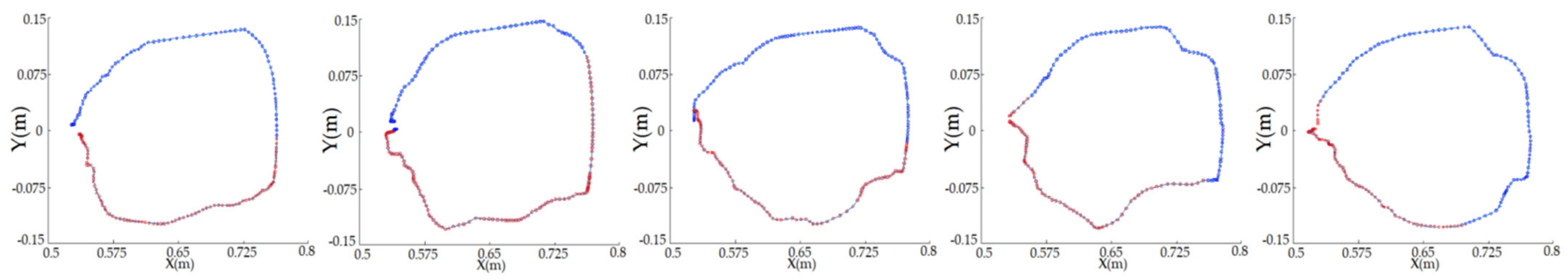
Figure 11 shows GMM classifies the task completion status of volunteer. 
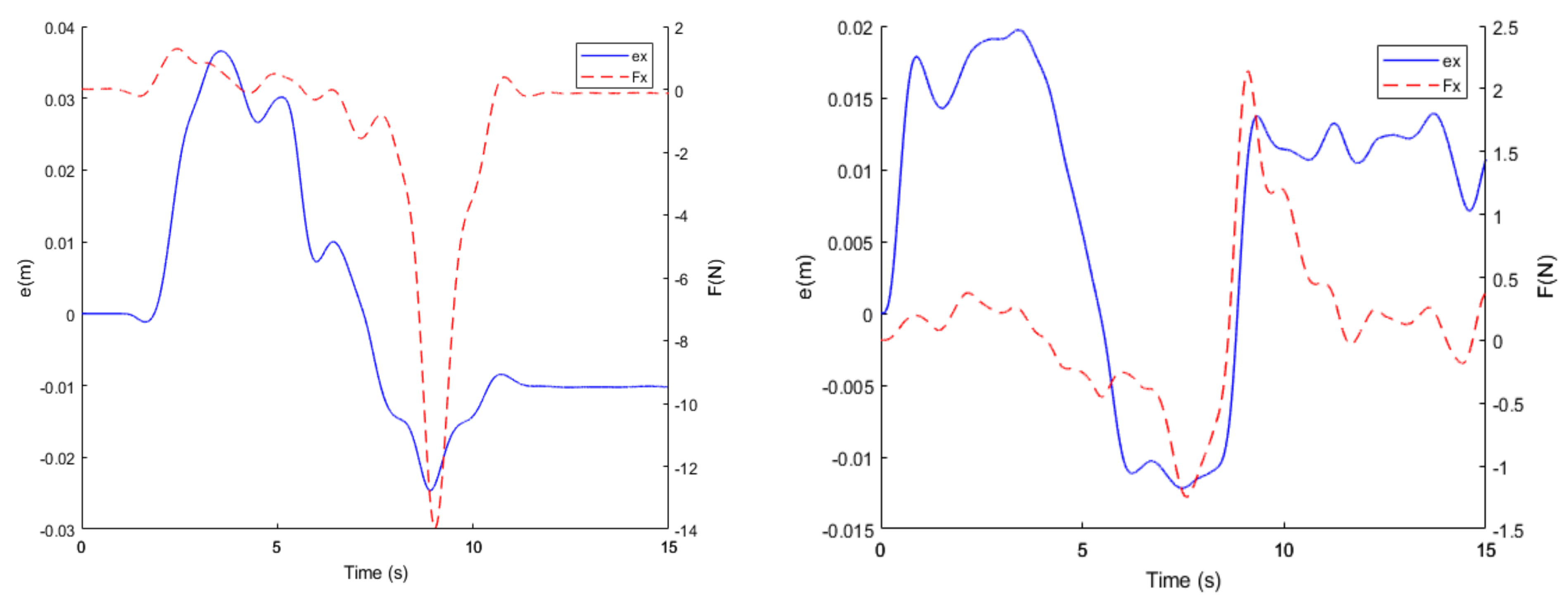
Figure 12 shows one period in which the subject completed the task, at 2–5 s. The GMM algorithm identifies the area where the subject is in active rehabilitation (the blue area in Figure 11), so within this area, even though there is a large error between the two sides of the subject (0.04 m > |ex| > 0.03 m, 0.02 m > |ey| > 0.015 m), and the controller does not provide much assistance force (0 N < |Fx| < 2 N, 0 N < |Fy| < 0.5 N), only when the end of the subject is in the passive rehabilitation area (the red area in Figure 11) will the controller be designed according to the error generated between the two sides of the subject (0.02 m < |ex| < 0.03 m, 0.01 m < |ey| < 0.015 m). This provides suitable assistance force (15 N < |Fx| < 10 N, 2.5 N < |Fy| < 1 N) to help the subject to complete the task.
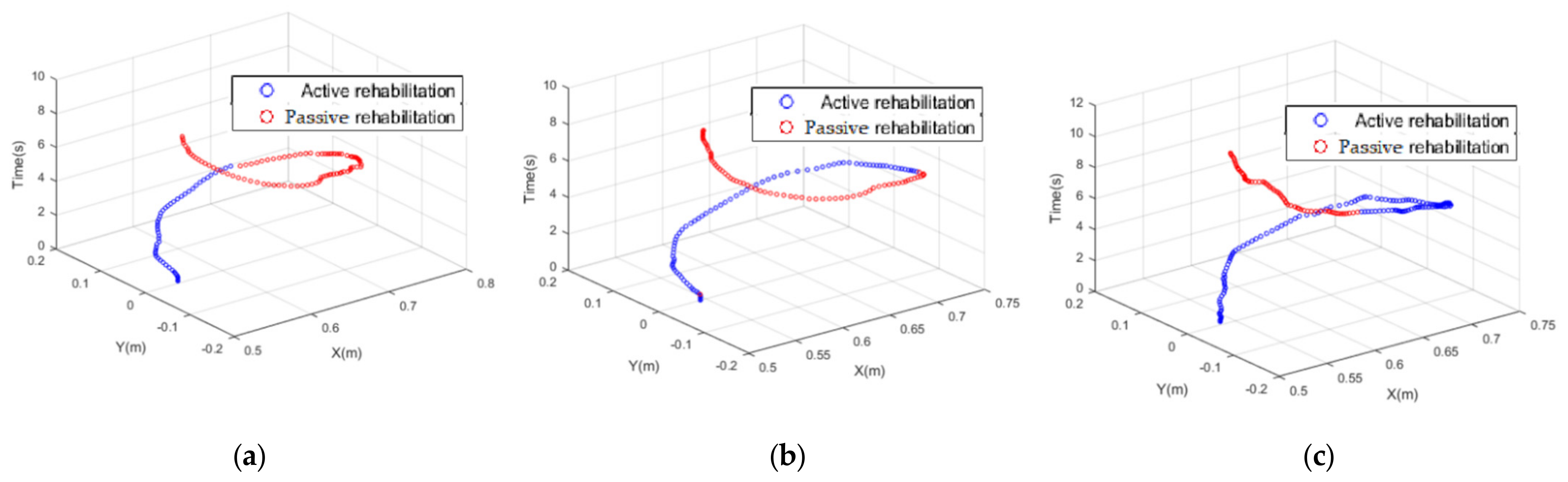
Figure 13 shows the different classification states that GMM can achieve according to the degree of active task completion of the subject, which further proves that the GMM algorithm can identify subjects simulating different muscle tension and provide corresponding assistance.

3.5. Security Verification

During the interaction between the patients and the rehabilitation robot, when PIL switches from the active rehabilitation position to the passive rehabilitation position, the sudden change of K value will lead to the mutation of the assistance force, which is not safe for the patients. Therefore, according to the transition function designed by Equation (12). The experiment was completed by a healthy volunteer aged 26 years and 178 cm in height. During the experiment, the volunteer was asked to simulate a patient interaction with the robot (drawing a circle task). During the movement of the experiment, 
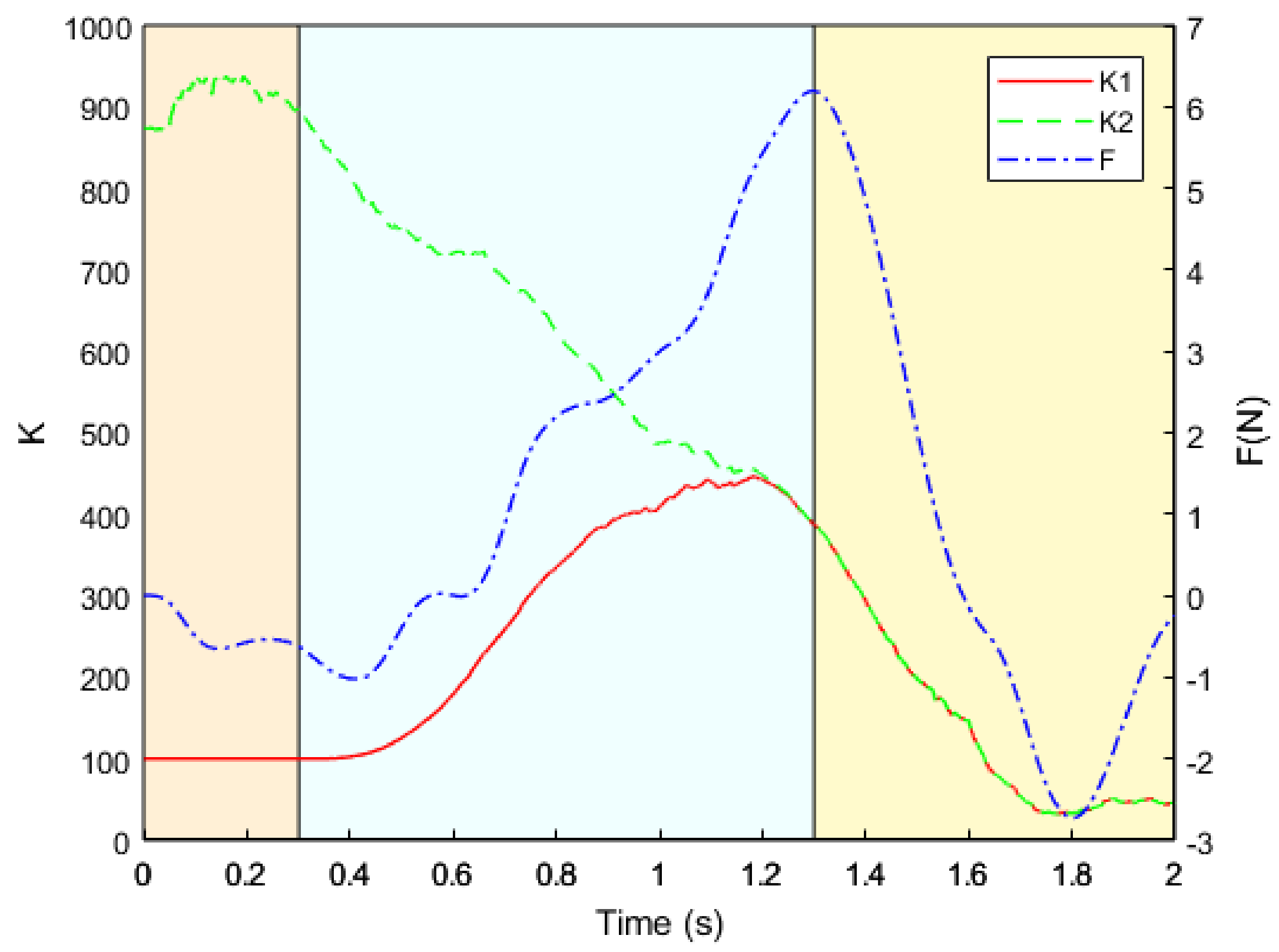
Figure 14 shows the change of K value when the active rehabilitation position is switched to the passive rehabilitation position.
In Figure 14, the red line K1 represents the real-time K value, the green line K2 represents the calculated K value, and the blue line F represents the change in the real-time assistance force. As can be seen from Figure 14, at about 0.3 s, the real-time K1 value begins to transition from the initial value of the active rehabilitation position to the K2 value calculated from the passive rehabilitation position, and one second later, the actual K1 value transitions to the calculated K2 value, at which point K1 = K2. It can be seen from this experiment that the designed transition function ensures the safety of the system and prevents the sudden change of K value from causing a surge in assistance force, which leads to risk with subjects.

4. Discussion

The AAN strategy is a relatively common assistance strategy in rehabilitation treatment. Nonetheless, the traditional AAN only succeeds in identifying whether the patients are currently able to complete the task [8,9]. The identification of the remaining ability of patients is more complex [5,7,10], without further identifying whether the patients are in a state of needing assistance when completing the task, which has great limitations. Nonetheless, because of the advantages of the GMM algorithm in data modeling [15], and how GMM has been successfully applied in robot demonstration learning [16,17,18], this paper proposes an AAN control strategy based on GMM in order to solve the problem of whether patients need assistance when completing tasks. Firstly, a new end-effector bilateral mirror upper limb rehabilitation robot was designed for patients with upper limb motor dysfunction, differentiating it from other upper limb rehabilitation robots [18,21] that can only be provided by the virtual environment, which cannot accurately express the real intention of the patient. Furthermore, with the upper limb rehabilitation robot proposed in this paper, patients could use the robot PFL to provide rehabilitation trajectory for PIL. Secondly, a new rehabilitation robot is a proposed AAN control strategy. Different from the traditional AAN control strategy, which only identifies whether the patients can complete the task at present [8,9], the recognition means the remaining ability of the patient is relatively complex [5,7,10]. In this paper, the GMM algorithm was used to classify the physical information of patients when they completed the task, and the results enabled us to guide the adaptive change of robot assistance force according to the degree of the patient’s participation; its advantage is that it can provide patients with as much assistance-as-needed (AAN). Finally, in order to induce the patient to recover, we designed a circular motion trajectory for the patients in the virtual environment. During the task, the AAN strategy can only provide the patients with assistance when necessary and according to the active participation degree that the patients can provide, allowing the patients to complete the task autonomously.
Compared with traditional rehabilitation robot assistance strategies, the proposed AAN control strategy for the bilateral upper limb mirror rehabilitation robot has the following advantages: The movement trajectory of PFL can more accurately reflect the patient’s movement intention; the AAN control strategy designed, based on GMM, can determine the areas that patients need assistance according to the degree of active participation of the patients; and although the rehabilitation robot designed in this paper can carry out rehabilitation training in three-dimensional space, this paper restricts the trajectory to a plane for subjects to better feel the assistance force. However, the controller proposed in this paper does not depend on the design of the training trajectory, and its performance has no influence on any spatial trajectory.

5. Conclusions

In this paper, a new bilateral upper limb mirror rehabilitation robot is designed, and a new AAN control strategy is proposed. The GMM algorithm is used to identify the current rehabilitation task stage of the patients, so as to provide appropriate assistance force. At the same time, the control strategy combines the virtual environment to mobilize the enthusiasm of the patients. The experimental results show that the proposed AAN control strategy can effectively provide appropriate assistance according to the classification stage of the PIL in the actual interaction between the patients and the rehabilitation robot. This is so the patients can better achieve the rehabilitation effect during the rehabilitation task as far as possible. Future work will focus on the performance of this strategy in clinical trials.

Author Contributions

Conceptualization, J.Z. and M.L.; methodology, M.L.; software, M.L.; validation, G.Z. and J.Z.; formal analysis, M.L.; investigation, M.L.; resources, G.F.; data curation, M.L.; writing—original draft preparation, M.L.; writing—review and editing, G.Z. and J.Z.; visualization, M.L.; supervision, G.Z. and X.Z.; project administration, G.Z.; funding acquisition, G.Z. All authors have read and agreed to the published version of the manuscript.

Funding

This research was supported by the following financial support for the research, authorship, and/or publication of this article: The Key Research and Development Program of Zhejiang Province (No.2019C03090); Zhejiang Provincial Natural Science Foundation of China under Grant (No. LGF21H170002); Major Scientific and Technological Projects in Ningbo City (No.2018B10073, 2019B10034 and 2020Z082).

Institutional Review Board Statement

This study was conducted according to the guidelines of The Declaration of Helsinki. Since the study did not test experiments on patients and only recruited healthy people for the preliminary experiment, ethical review and approval were abandoned in this study. In the next study, experiments on patients will be conducted and ethical review and approval will be applied for.

Informed Consent Statement

The informed consent has been obtained from the patient(s) to publish this paper.

Data Availability Statement

The original data contributions presented in the study are included in the article, further inquiries can be directed to the corresponding authors.

Conflicts of Interest

The authors declare no conflict of interest.

References

  1. World Health Organization. World Health Statistics Overview 2019: Monitoring Health for the SDGs, Sustainable Development Goals; World Health Organization: Geneva, Switzerland, 2019. [Google Scholar]
  2. Ringleb, P.; Bousser, M.; Ford, G.; Bath, P.; Brainin, M.; Caso, V.; Cervera, A.; Cordonnier, C.; Csiba, L. Guidelines for management of ischaemic stroke and transient ischaemic attack. Cerebrovasc. Dis. 2008, 26, 571–572. [Google Scholar]
  3. Basteris, A.; Nijenhuis, S.M.; Stienen, A.H.A.; Buurke, J.H.; Prange, G.B.; Amirabdollahian, F. Training modalities in robot-mediated upper limb rehabilitation in stroke: A framework for classification based on a systematic review. J. Neuroeng. Rehabil. 2014, 11, 111. [Google Scholar] [CrossRef] [Green Version]
  4. Bertani, R.; Melegari, C.; Maria, C.; Bramanti, A.; Bramanti, P.; Calabrò, R.S. Effects of robot-assisted upper limb rehabilitation in stroke patients: A systematic review with meta-analysis. Neurol. Sci. 2017, 38, 1561–1569. [Google Scholar] [CrossRef] [PubMed]
  5. Lin, B.-S.; Chen, J.-L.; Hsu, H.-C. Novel Upper-Limb Rehabilitation System Based on Attention Technology for Post-Stroke Patients: A Preliminary Study. IEEE Access 2018, 6, 2720–2731. [Google Scholar] [CrossRef]
  6. Hogan, N.; Krebs, H.I.; Rohrer, B.; Palazzolo, J.J.; Di Pietro, L.; Fasoli, S.E.; Stein, J.; Hughes, R.; Frontera, W.R.; Lynch, D.; et al. Motions or muscles? Some behavioral factors underlying robotic assistance of motor recovery. J. Rehabil. Res. Dev. 2006, 43, 605–618. [Google Scholar] [CrossRef] [PubMed]
  7. Wang, J.; Wang, W.; Hou, Z.-G. Toward Improving Engagement in Neural Rehabilitation: Attention Enhancement Based on Brain–Computer Interface and Audiovisual Feedback. IEEE Trans. Cogn. Dev. Syst. 2020, 12, 787–796. [Google Scholar] [CrossRef]
  8. Pehlivan, A.U.; Sergi, F.; O’Malley, M. A Subject-Adaptive Controller for Wrist Robotic Rehabilitation. IEEE/ASME Trans. Mechatron. 2014, 20, 1338–1350. [Google Scholar] [CrossRef]
  9. Shi, D.; Zhang, W.; Zhang, W.; Ding, X. Assist-as-needed attitude control in three-dimensional space for robotic rehabilitation. Mech. Mach. Theory 2020, 154, 104044. [Google Scholar] [CrossRef]
  10. Teramae, T.; Noda, T.; Morimoto, J. EMG-Based Model Predictive Control for Physical Human–Robot Interaction: Application for Assist-As-Needed Control. IEEE Robot. Autom. Lett. 2018, 3, 210–217. [Google Scholar] [CrossRef]
  11. Huang, H.; Zhang, F.; Hargrove, L.J.; Dou, Z.; Rogers, D.R.; Englehart, K.B. Continuous Locomotion-Mode Identification for Prosthetic Legs Based on Neuromuscular–Mechanical Fusion. IEEE Trans. Biomed. Eng. 2011, 58, 2867–2875. [Google Scholar] [CrossRef] [PubMed] [Green Version]
  12. Wei, Y.; Bajaj, P.; Scheidt, R.; Patton, J.L. Visual Error Augmentation for Enhancing Motor Learning and Rehabilitative Relearning. In Proceedings of the International Conference on Rehabilitation Robotics, Chicago, IL, USA, 28 June–1 July 2005. [Google Scholar]
  13. Emken, J.L.; Benitez, R.; Reinkensmeyer, D.J. Human-robot cooperative movement training: Learning a novel sensory motor transformation during walking with robotic assistance-as-needed. J. Neuroeng. Rehabil. 2007, 4, 8. [Google Scholar] [CrossRef] [Green Version]
  14. Chen, Z.; Wang, S.; Wang, J.; Xu, K.; Lei, T.; Zhang, H.; Wang, X.; Liu, D.; Si, J. Control strategy of stable walking for a hexapod wheel-legged robot. ISA Trans. 2021, 108, 367–380. [Google Scholar] [CrossRef]
  15. Moreira, L.; Figueiredo, J.; Vilas-Boas, J.; Santos, C. Kinematics, Speed, and Anthropometry-Based Ankle Joint Torque Estimation: A Deep Learning Regression Approach. Machines 2021, 9, 154. [Google Scholar] [CrossRef]
  16. Michieletto, S.; Tonin, L.; Antonello, M.; Bortoletto, R.; Spolaor, F.; Pagello, E.; Menegatti, E. GMM-Based Single-Joint Angle Estimation Using EMG Signals. In Advances in Intelligent Systems and Computing; Springer: Singapore, 2016; pp. 1173–1184. [Google Scholar]
  17. Najafi, M.; Adams, K.; Tavakoli, M. Robotic Learning from Demonstration of Therapist’s Time-Varying Assistance to a Patient in Trajectory-Following Tasks. In Proceedings of the International Conference on Rehabilitation Robotics, London, UK, 17–12 July 2017. [Google Scholar]
  18. Fong, J.; Tavakoli, M. Kinesthetic teaching of a therapist’s behavior to a rehabilitation robot. In Proceedings of the International Symposium on Medical Robotics, Atlanta, GA, USA, 1–3 March 2018. [Google Scholar]
  19. Najafi, M.; Sharifi, M.; Adams, K.; Tavakoli, M. Robotic assistance for children with cerebral palsy based on learning from tele-cooperative demonstration. Int. J. Intell. Robot. Appl. 2017, 1, 43–54. [Google Scholar] [CrossRef]
  20. Kaya, M.D.; Hasiloglu, A.S.; Bayramoglu, M.; Yesilyurt, H.; Ozok, A.F. A new approach to estimate anthropometric measurements by adaptive neuro-fuzzy inference system. Int. J. Ind. Ergon. 2003, 32, 105–114. [Google Scholar] [CrossRef]
  21. Klopčar, N.; Lenarčič, J. Kinematic Model for Determination of Human Arm Reachable Workspace. Meccanica 2005, 40, 203–219. [Google Scholar] [CrossRef]
  22. Zhang, L.; Guo, S.; Sun, Q. Development and Assist-As-Needed Control of an End-Effector Upper Limb Rehabilitation Robot. Appl. Sci. 2020, 10, 6684. [Google Scholar] [CrossRef]
  23. Meng, Q.; Xie, Q.; Yu, H. Upper-Limb Rehabilitation Robot: State of the Art and Existing Problems. In Proceedings of the 12th International Convention on Rehabilitation Engineering and Assistive Technology, Shanghai, China, 13–16 July 2018. [Google Scholar]
  24. Rodrigues, T.A.; Goroso, D.G.; Westgate, P.M.; Carrico, C.; Batistella, L.R.; Sawaki, L. Slow Versus Fast Robot-Assisted Locomotor Training After Severe Stroke. Am. J. Phys. Med. Rehabil. 2017, 96, S165–S170. [Google Scholar] [CrossRef]
  25. Maaref, M.; Rezazadeh, A.; Shamaei, K.; Tavakoli, M. A Gaussian Mixture Framework for Co-Operative Rehabilitation Therapy in Assistive Impedance-Based Tasks. IEEE J. Sel. Top. Signal Process. 2016, 10, 904–913. [Google Scholar] [CrossRef]
  26. Naghdi, S.; Ansari, N.N.; Mansouri, K.; Hasson, S. A neurophysiological and clinical study of Brunnstrom recovery stages in the upper limb following stroke. Brain Inj. 2010, 24, 1372–1378. [Google Scholar] [CrossRef] [PubMed]
  27. Moon, T.K. The expectation-maximization algorithm. IEEE Signal Processing Mag. 1996, 13, 47–60. [Google Scholar] [CrossRef]
  28. Flash, T.; Hogan, N. The coordination of arm movements: An experimentally confirmed mathematical model. J. Neurosci. 1985, 5, 1688–1703. [Google Scholar] [CrossRef] [PubMed]
  29. Tang, Z.Q.; Heung, H.L.; Tong, K.Y.; Li, Z. Model-based online learning and adaptive control for a “human-wearable soft robot” integrated system. Int. J. Robot. Res. 2021, 40, 256–276. [Google Scholar] [CrossRef]
Figure 1. Overall design of mirror upper limb rehabilitation robot.
Machines 10 00076 g001
Figure 2. Coordinates of each joint of the affected side manipulator.
Machines 10 00076 g002
Figure 3. The e is the error between the coordinates on both sides of the mechanical arm, τ 1 , τ 2 , τ 3 is the torque of the three joints of the affected side mechanical arm, F s is the information of the force sensor. The control strategy of the end-effector bilateral mirror upper limb rehabilitation robot mainly includes the adaptive impedance controller, GMM algorithm, gravity compensation and friction compensation. The cartesian position at the end of the robotic arm is calculated by the forward kinematics of each joint angle of the mechanical arm. The GMM algorithm identifies the task classification map based on each task completion and then guides the adaptive controller to provide the appropriate assistance moment.
Machines 10 00076 g003
Figure 4. The prototype of the mirror upper limb rehabilitation robot.
Machines 10 00076 g004
Figure 5. Block diagram of electrical system of the mirror upper limb rehabilitation robot.
Machines 10 00076 g005
Figure 6. Virtual environment Task.
Machines 10 00076 g006
Figure 7. Subject participated in the drawing circle task experiment.
Machines 10 00076 g007
Figure 8. Volunteer simulated healthy person and patient EMG signals.
Machines 10 00076 g008
Figure 9. The volunteer simulates healthy people to interact with the robot, in which the blue part is the active rehabilitation area and the red part is the passive rehabilitation area.
Machines 10 00076 g009
Figure 10. The volunteer simulates a patient to interact with the robot, in which the blue part is the active rehabilitation area and the red part is the passive rehabilitation area.
Machines 10 00076 g010
Figure 11. GMM classifies the task completion status of volunteers, in which the blue part is the active rehabilitation area and the red part is the passive rehabilitation area.
Machines 10 00076 g011
Figure 12. Bilateral error and assistance force in the X and Y-axis direction of the task. The blue line is the error in each axis direction between the two sides, and the red line is the assistance force in each axis direction.
Machines 10 00076 g012
Figure 13. (ac) shows the different states that the GMM can achieve, in which the blue part is the active rehabilitation area and the red part is the passive rehabilitation area.
Machines 10 00076 g013
Figure 14. The change of K value when the active rehabilitation position is switched to the passive rehabilitation position. The left part is the active rehabilitation area, the middle part is the transition area, and the right part is the passive rehabilitation area.
Machines 10 00076 g014
Table 1. DH parameters of the manipulator.
Link i θ i α i 1 a i 1 d i
1 θ 1 90 ° 0 ° 0 0
2 θ 2 0 ° 90 ° 0 d 1
3 θ 3 0 ° 0 ° a 1 0
4 θ 4 0 ° 0 ° a 2 d 2
Table 2. Mean error and mean assistance force of subject at different classification stages in each task period.
Period 1Period 2Period 3Period 4Mean
Active rehabilitationMean error (m)0.02150.01070.01040.01650.0148
Mean assistance force (N)0.42100.19390.16100.49700.3182
Passive rehabilitationMean error (m)−0.0076−0.0153−0.0159−0.0069−0.0114
Mean assistance force (N)−3.5117−6.3841−6.7778−6.6934−5.8418
Publisher’s Note: MDPI stays neutral with regard to jurisdictional claims in published maps and institutional affiliations.

