Article

Design and Analysis of Mechanical Characteristics of EAP Flexible Drivers

1
School of Mechatronical Engineering, Beijing Institute of Technology, Beijing 100081, China
2
China Academy of Aerospace Science and Innovation, Beijing 100871, China
3
College of Engineering, Peking University, Beijing 100871, China
*
Author to whom correspondence should be addressed.
Machines 2022, 10(12), 1241; https://doi.org/10.3390/machines10121241
Submission received: 14 November 2022 / Revised: 14 December 2022 / Accepted: 16 December 2022 / Published: 19 December 2022

Abstract

:
Electroactive polymer(EAP) is a “smart material” with high energy density, high electromechanical energy conversion efficiency, simple structure, good adaptability to the working environment, etc. It can be made into various shapes to realize flexible drivers. At present, the common EAP actuator is mainly composed of EAP film wound on a spring, and the output performance of this type of actuator is related to the spring stiffness, film prestretching rate, voltage, and other factors. Its working process is actually an electromechanical coupling process. In this paper, two types of cylindrical actuators are designed and tested. The electromechanical coupling mathematical model is constructed to simulate the driver. According to the experimental and simulation results, the relationship between the output displacement and elongation strain of EAP actuator and voltage, spring stiffness, and tensile rate is analyzed. It provides a reference and basis for the design of similar actuators.

1. Introduction

EAP material, as an emerging material for actuators, has good deformation retention, simple structure, light weight, low price, and easy processing and manufacturing, and is more suitable for flexible actuators than piezoelectric ceramics with high brittleness and low strain and shape memory metals with unpredictable deformation and slow response [1,2]. Table 1 shows the comparison of EAP materials with conventional materials in terms of drive performance. EAP materials offer good actuation performance without the need for rigid frames, and they also have good prospects for application in the field of bionic artificial muscles [3,4].
EAP materials can be divided into electronic and ionic types according to the transduction mechanism [5]. The induced strain of both electronic EAP and ionic EAP can be designed as bending, tensile, or compressive strain [6]. Electronic EAP is favored by researchers for its mechanical properties comparable to biological muscles, fast response, and good flexibility, as shown in Table 2, which compares the performance advantages and disadvantages of ionic and electronic EAP materials [7,8]. Researchers have carried out a lot of research on dielectric EAP materials. In 1998, Pelrine of SRI (Stanford Research Institute) proposed that the electrostatic pressure under the electric field exists only at the junction of the film surface and the electrode region, and the mechanical properties of the film have no direct effect on the electric field, and its deformation is only the passive mechanical behavior of the elastomer under the action of the electrostatic pressure [9]. In 2001, Kofod performed uniaxial tensile tests on VHB 4910 films to determine the range of applicability of different hyperelastic models [10]. Suo established the free energy function consisting of strain energy and electric field energy from the energy perspective, and gave the preliminary intrinsic relationship of its dielectric deformation under the force–electric field by variational treatment of the free energy of the adiabatic system. The significant feature of this method is that it is valid for both elastic or inelastic dielectrics [11]. Pelrine et al. proposed an equation to calculate the electrostatic force in a dielectric elastomer system by using a flexible electrode as the driving means of polymer dielectric electrostriction, and proposed a new physical explanation of the electrostatic force acting on the dielectric elastomer film. Its contribution comes from in-plane and out-of-plane stresses [12]. In recent years, due to the large voltage demand that hinders the application of EAP in many fields, people have begun to research the field of enhancing the driving ability of EAP materials. Hossain realized the driving enhancement in EAP by introducing high dielectric fillers into the matrix material in the uncured stage. They presented a phenomenologically inspired large strain framework for simulating the curing process of particle-filled electro-active polymers with a dispersion-type anisotropy that can work under the influence of an electromechanically coupled load [13]. Sharma 3D-printed EAPs with polyvinylidene fluoride as the matrix and barium titanate and graphene as the reinforcements. The factors affecting the mechanical properties of the finished product were explored [14]. Kanan considered the material modeling and corresponding finite element implementation of electromechanical coupling in fiber-reinforced electroactive polymers, and proposed a constitutive model that considers both the electroviscoelastic behavior of the isotropic matrix and the influence of unidirectional fiber on the hyperelastic response and viscous behavior of the entire composite. Studies have shown that for soft EAP simulations with relatively rigid fibers, the use of mixed finite elements improves convergence behavior [15]. In addition to the nature of EAP materials, flexible electrodes also have an important impact on the life and efficiency of EAP materials. Mehnert used experimental data and modeling methods to explore the effect of flexible electrodes on the viscoelastic behavior of EAPs materials [16]. Munteanu analyzed the application potential of mixed conductive paint pigments composed of zinc ferrite and polyaniline as electroactive and anticorrosion coatings from the electrorheological perspective [17].
There are many types of EAP actuators, such as rhombic, cylindrical, conical, butterfly, etc. Although the motion forms of different structure types of actuators are different, they have the same actuation mechanism, in which the dielectric elastomer is deformed under the excitation of electric field to output displacement and force [18,19,20]. As early as the late 1990s, Pelrine et al. designed and fabricated various forms of dielectric EAP actuators in the laboratory through the study of dielectric elastomers, which paved the way for the continued development of drive units [21]. In 2007, a folding actuator was developed by a research group at the University of Pisa, Italy. The folded actuator can be deformed under the energized condition and the strain can be stabilized up to 10% [22]. P. Lochmatter et al. from the Swiss Federal Institute of Technology designed and fabricated a dielectric EAP driver with a shell structure. When energized, the driving unit deforms under the action of Maxwell stress, and deflects in two directions of single degree of freedom of the shell structure through the tension of the dielectric EAP films on both sides [23]. In 2020, Wang Yong of the Harbin Institute of Technology designed a new flexible bionic machine fish based on the principle of dielectric EAP materials in combination with a complex underwater environment, and gave a detailed description of its structure and design process [24]. In addition to the structural design of the EAP driver, the problems of precise control, modeling, and calculation of the driver have also been partially solved. Considering the actual working conditions of EAP-based actuators under different input control voltages and external mechanical loads, Jiang developed a feedforward compensation scheme to dynamically eliminate the creep phenomenon that significantly reduces creep caused by changes in input control voltage and load [25]. Because EAP actuators are usually designed as shell structures, in this case, the application of standard finite element formulas will lead to various locking pathology. Bishara developed a numerical scheme to simulate the viscoelastic response of electroactive polymers under finite deformation using a simplified mixed finite element scheme. It eliminates possible volume locking in electroactive polymers and improves computational efficiency while avoiding static condensation. Subsequently, Bishara proposed an advanced low-order solid shell model to simulate electroactive polymers, and modified the strain measure by assuming natural inhomogeneous strain and enhanced assumed strain. It alleviates various locking diseases [26,27].
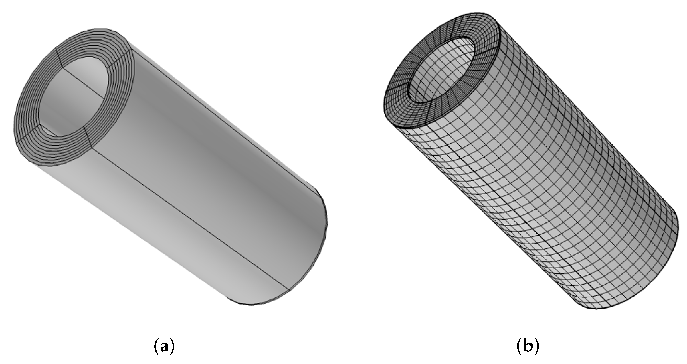
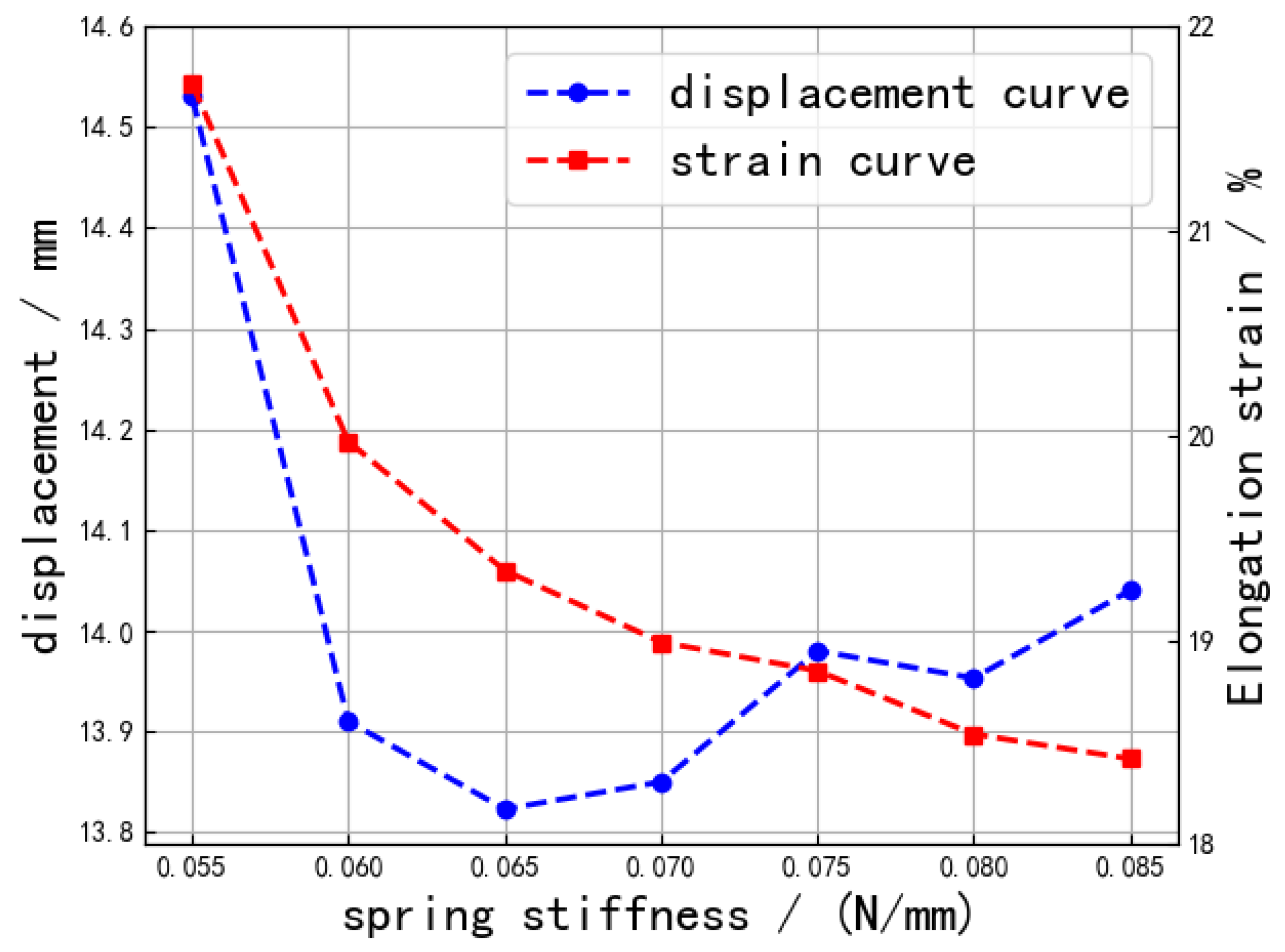
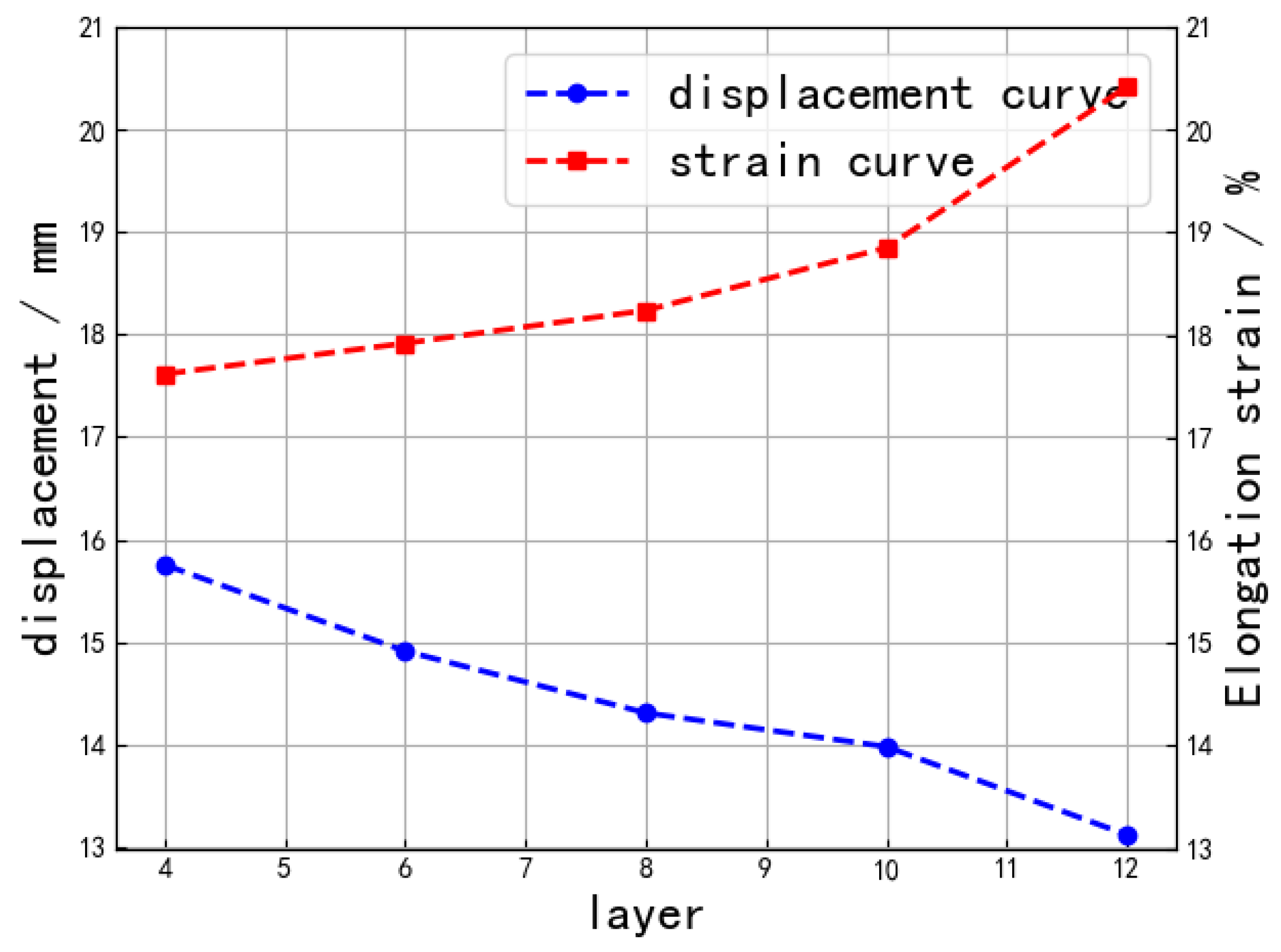
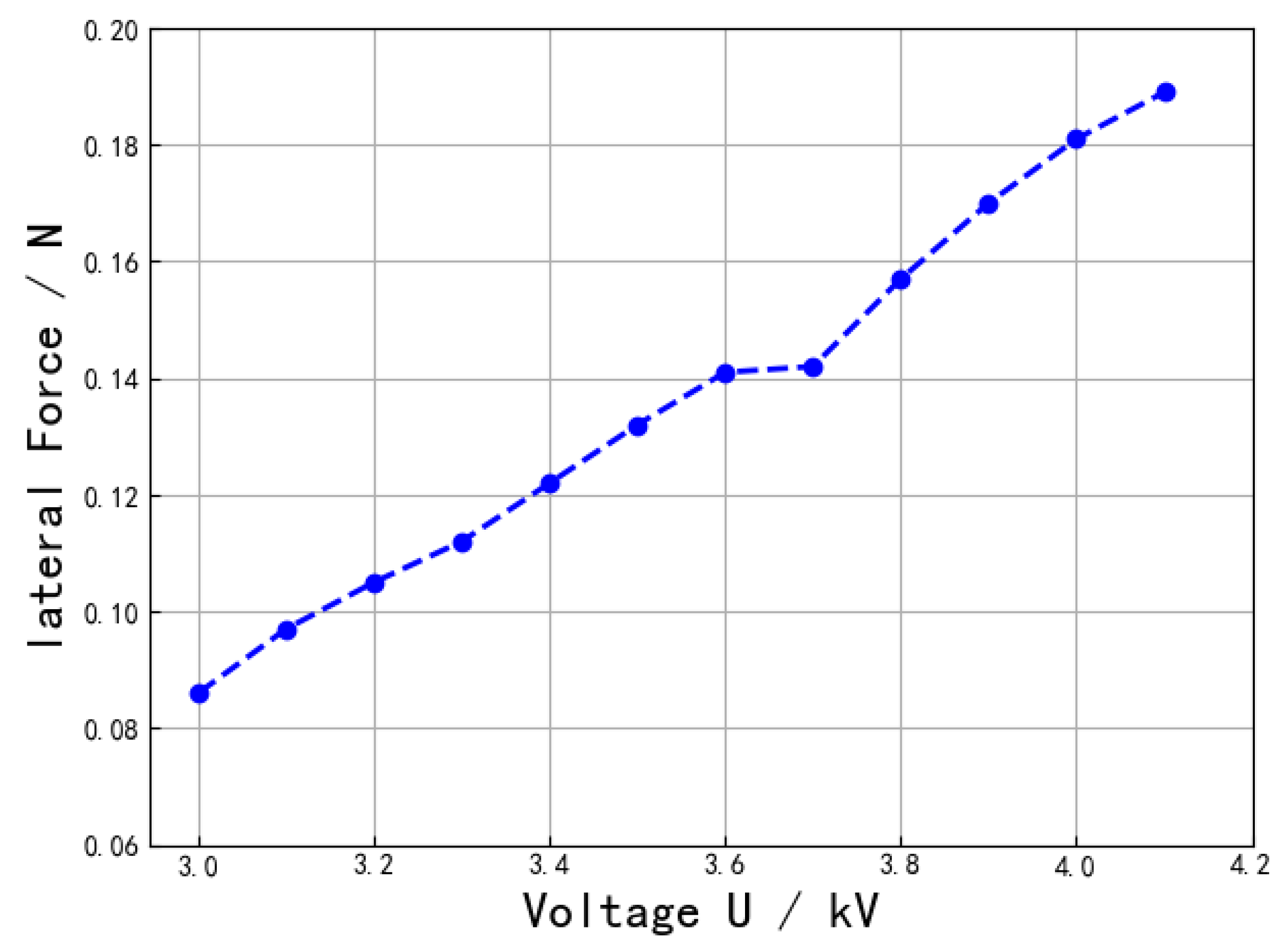
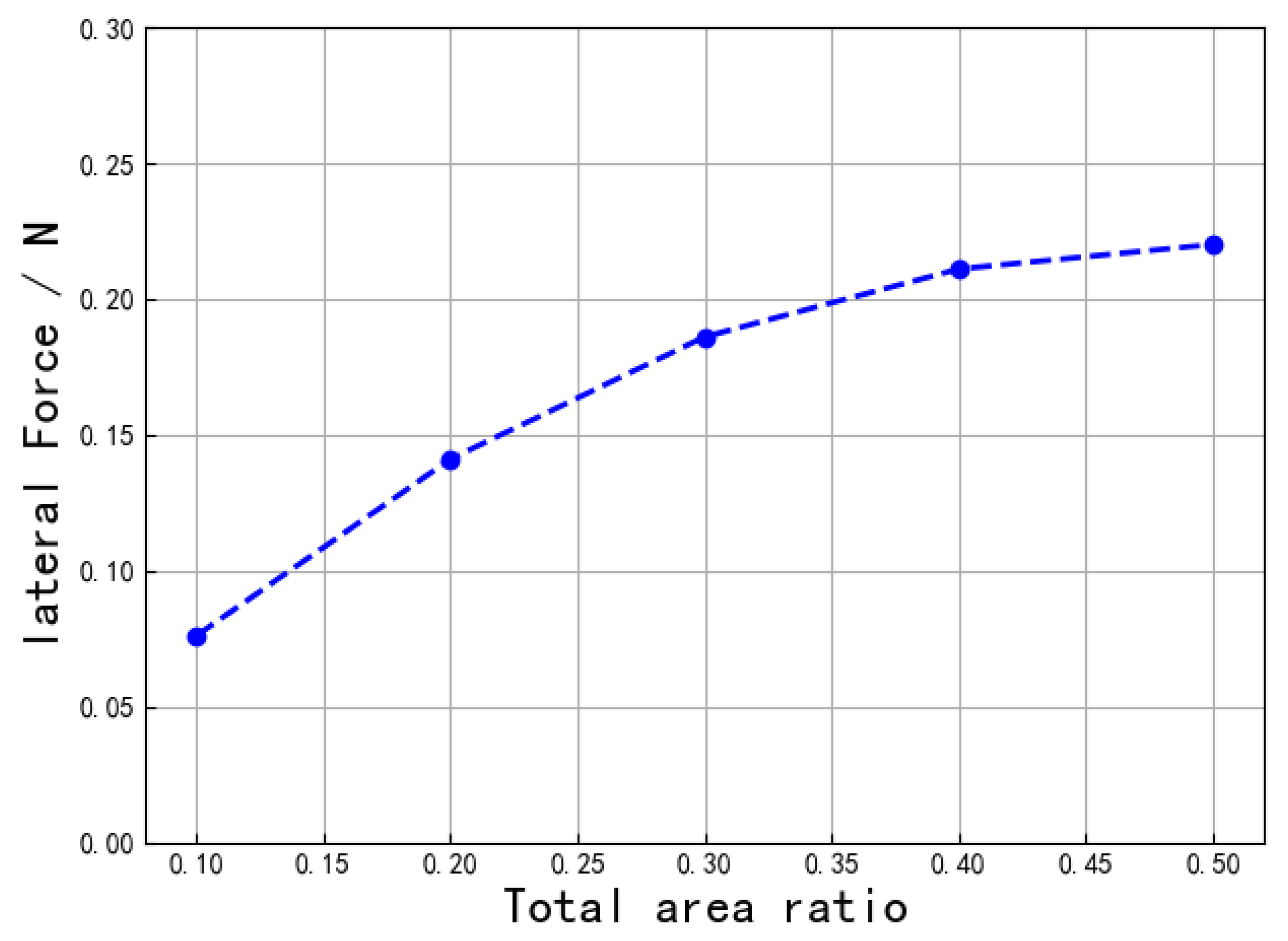
Although the research and application of EAP materials have been greatly developed, the simulation of the electromechanical coupling part of EAP materials is still not mature. In this paper, two cylindrical actuators are designed and fabricated by using the change of the coating layer. One is a single-degree-of-freedom actuator that can realize a telescopic motion, and the other is a two-degree-of-freedom actuator that can realize a telescopic and bending motion. Experiments are designed for the factors affecting the actuator, and the corresponding electromechanical coupling model is established for simulation based on the experiments. According to the experimental and simulation results. the effects of the actuator film stretching rate, voltage, and spring stiffness on the mechanical properties of the actuators are analyzed.

2. Materials and Methods

2.1. Analysis of Drive Unit Model

The analytical model of the cell is developed using elasticity theory, and for simplicity, the following assumptions are made:
  • The unit contains N concentric circular tubes; each tube consists of a circular membrane (Figure 1), and angle 2 ϕ 1 is constant and longitudinally symmetric, assuming that the addition of electric drive does not cause a change in the angular position of the active and passive regions.
  • In the bending state, the axis of each tube is a circular arc and coincides with the axes of the other tubes, i.e., the curvature of the axes is fixed along the axis direction. In the elongated state, the axes are straight and coincide.
  • The spring is a flexible rod with a circular cross-section that supports the EAP membrane from the inside and whose diameter does not vary with the elongation of the spring.
  • The EAP membrane is incompressible, superelastic, and time-independent, and the electrodes are soft enough not to prevent the EAP from deforming.
The strain energy function W is used to describe the hyperelastic behavior of the EAP film, which expresses the strain energy of the material as a function of deformation. Here, the Yeoh strain energy function is used with the following functional expression for the strain energy density function W [28].
W = C 10 ( I 1 3 ) + C 20 ( I 1 3 ) + C 30 ( I 1 3 )
where C 10 , C 20 , and C 30 are the material constant, and I 1 is the first invariant with respect to the left Cauchy–Green deformation tensor.
I 1 = λ 1 2 + λ 2 2 + λ 3 2
where λ 1 , λ 2 , and λ 3 are the principal elongation in each direction.
Due to the constant volume before and after deformation, dielectric EAP is a completely incompressible material; for completely incompressible materials there are:
λ 1 λ 2 λ 3 = 1
For fully incompressible materials, the nominal stress σ i (force per unit area of the current undeformed structure) can be obtained by deriving the strain energy function with respect to the principal elongation (i = 1, 2, 3) as follows:
σ i = W λ i 1 λ i p
where p is the hydrostatic pressure; its value depends on the dynamic boundary conditions. For uniaxial stretching (stretching along the 1 direction), the sum of the nominal stresses in both the 2 and 3 directions is 0. According to this boundary condition, from (1)–(3), we obtain:
λ 2 = λ 3 = 1 λ 1
The uniaxial stretching from (1) to (6) yields the expression for the nominal Yeoh model as:
σ 1 = 2 ( λ 1 1 λ 1 2 ) [ C 10 + 2 C 20 ( λ 1 2 + 2 λ 1 3 ) + 3 C 30 ( λ 1 2 + 2 λ 1 3 ) ]

2.2. The Design and Manufacture of Drive Units

2.2.1. Single-Degree-of-Freedom Actuator

The material used for the drive unit is VHB4910. Figure 2 shows the structure of the cylindrical EAP drive unit, which is composed of a preload element, a spiral dielectric type EAP film (made by winding), and end caps on both sides. End caps are assembled at both ends of the compression spring, and the EAP film, which is prestretched and coated with electrodes, is uniformly wound on the compression spring and end caps to form a hollow cylindrical structure. The electrodes are uniformly coated on the film for winding, and the finished actuator can perform a unidirectional stretching motion.

2.2.2. Two-Degree-of-Freedom Actuator

The EAP film flexible electrode coating method affects actuator displacement. To realize the linear stretching and continuous bending functions, it is necessary to divide the linear winding drive unit into two drive units along the axis to separate the electrodes on the left and right sides of the film, as shown in Figure 3a, which requires the electrodes to be coated in pieces [29]. The most direct way is to divide the electrodes on each circle of the film into two unconnected areas. Each area is led with leads, and the leads of the overlapping electrode areas on the same side are connected together after winding, but the leads are too many in number and fall off easily, and the volume of the end of the drive unit increases after winding. In order to reduce the number of electrode leads, a comb-shaped electrode, as shown in Figure 3b, is used.
The winding process of EAP film is shown in Figure 3c, using the structure form of two-layer film with three electrodes, which are the middle electrode, the top, and the bottom electrode. The upper or lower electrodes are all coated, and the middle electrode is coated in a comb shape. When the electricity is applied, electrostatic pressure is generated only where there are electrodes on both sides of the film. Since the top and bottom electrodes are in contact after winding, the top and bottom electrodes can be coated on one side only. The electrode teeth on the same electrode area overlap after winding, so that the drive unit is divided into two drive units along the axis. At this point, the drive unit requires only three leads, a, b, and c, connecting a pair of comb-tooth electrodes and the upper electrode, respectively. When a voltage is applied between the comb-like electrodes a or b and the upper electrode, a continuous bending in both directions with one degree of freedom is produced. When a voltage is applied between the comb-like electrodes a and b and the upper electrode, a linear stretching with one degree of freedom will be produced.

2.3. Manufacture of Drive Units

The dielectric EAP film is clamped around a number of self-tensioning collets, which are solidly attached to pulleys on a guide. The model is shown in Figure 4a.
When the EAP film is stretched in two directions, the pulleys on the four side rails will automatically roll along the rails to adjust its position to ensure the uniform stretching of the EAP film and achieve the required stretching multiplier. The two layers of EAP film coated with electrodes are fixed on the frame, the winding machine is used to realize the winding, and the EAP film is wound on the spring and end cover by gear rotation, as shown in Figure 4b. As the EAP film has a certain thickness, the diameter of the end cap increases as the number of layers of EAP film attached to the end cap of the drive unit increases during the winding process. This is shown in Figure 5.
The end cap diameter is D, the biaxial stretching rates of films are x 1 and y 1 , respectively, β is the angle between the membrane holder and the motion plane of the winding shaft, m is the modulus of the gear/rack, and z is the number of teeth of the gear.
β can be determined by calculating that
t a n ( β ) = 2 x 1 y 1 m z
In the winding process to prevent air bubbles between the film, after the end of winding, the unit and the winding axis are removed. The end cover at both ends of the unit are set on the heat shrinkable sleeve and heated, so that the sleeve shrinkage is pressed on the end cover to prevent the axial shrinkage of the film.

2.4. The Experiment of Actuating Unit

2.4.1. Uniaxial Tensile Experiment

The experiments here are divided into two parts, both to provide material parameters for the simulation part. Firstly, the material parameters C 10 , C 20 , and C 30 of EAP film were obtained by uniaxial tensile test. The measured values are shown in Table 3.
Next, we performed the electrification experiment of the single-axis actuator under static load. We made a single-axis dielectric high elastic actuator. The overall length of the actuator is approximately 56–58 mm; the width is approximately 45 mm; the thickness is approximately 12 mm; and the mass is approximately 11.65–11.75 g. The upper end of the actuator is suspended on an iron stand, and a static load with a fixed mass of 150 g is suspended at the lower end, as shown in Figure 6. The displacements under different voltages were measured, as shown in Table 4.

2.4.2. Experiments of Single-Degree-of-Freedom Actuating Unit

For different compression spring parameters, EAP film prestretch rate, λ , and number of coiling turns, N, a comparative test table was designed, as shown in Table 5. Each group of single-degree-of-freedom drive units was fabricated and tested according to the different parameters listed in the table.
After the cylindrical drive unit was fabricated, the output displacement was measured. The test equipment needed to measure the output displacement of the drive unit mainly included digital display high-voltage DC power supply, scale, drive unit mounting frame, etc. The test equipment is shown in Figure 7.
For each group of drive units in Table 5, although the precompression of the compression spring is the same at the time of fabrication, and the width of the EAP film area of the initially applied flexible electrode is the same, the effective lengths of the drive units differ when they reach the static equilibrium state due to the different stiffness of the compression spring and the different prestretching rate of the EAP film, so the performance of the drive units is measured by the elongation strain of the drive units at different voltages. The elongation strain ϵ z generated by the drive unit at different voltages can be expressed as the following equation:
ϵ z = s l
where s denotes the output displacement of the drive unit and l denotes the effective length of the drive unit (the area of the EAP film in the drive unit where deformation actually occurs).
We measured the effective length of each group of drive units, calculated the elongation strain at different voltages, respectively, and plotted the relationship curve between elongation strain and voltage.

2.4.3. Experiments of Two-Degree-of-Freedom Actuating Unit

A 15-layer two-degree-of-freedom actuator was wound according to the parameters of test 1 in Table 5. The powered area of the driver is half of the total area. The lateral force of the driver is measured when the voltage changes from 3.0 kV to 4.1 kV. To test the lateral output force of the unit during the bending process, a test setup was constructed, as shown in Figure 8a. One end of the unit is driven by a stepper motor through the rotation arm, and the other end is in contact with a force sensor. The lateral output force during bending can be obtained by controlling the rotation of the stepper motor, as shown in Figure 8b.

2.5. Simulation of Actuating Unit

2.5.1. Electromechanical Coupling Model

Countries around the world are working to transform EAP materials into select actuators, and are involved in developing effective computational chemistry models, integrated materials science, and electromechanical analysis tools [30]. However, an electromechanical coupling model of EAP material type is not available due to simulation software used, so the following mathematical model of electromechanical coupling is constructed based on this specific experimental model: It is assumed that when a potential difference exists in one direction of the EAP film, an electric field force is generated on the surface perpendicular to the potential difference. The direction of the electric field force is to make the film have a tendency to expand outward. The size of the electric field force is related to the size of the electric potential difference, and there is a functional relationship between the two. The unit electric field force generated by the potential difference defined here can be obtained by experiment and calculation. The specific experiment can be seen in the uniaxial tensile test. When the film is stretched, stress is generated inside. When the stress is equal to the unit electric field force, the ratio of the stretch part of the film to the original length is defined as the maximum release stretch rate. Under the action of voltage, although the film is in a stretched state, it does not need additional external force to maintain the state, but if the stretch part exceeds this critical value, additional external force is required. The relationship between the maximum release strain rate and the voltage intensity can be fitted from the data in Table 4, as shown in Table 6. Thus, electromechanical coupling occurs. When there is a voltage in one direction of the film, a unit electric field force can be added on the side perpendicular to the direction and subjected to tension. Its size is equal to the internal stress of the film in the state of maximum release tensile rate.

2.5.2. Simulation Content

The simulation software is COMSOL Multiphysics. The Yeoh model is used for the intrinsic equations of the model; see Reference Formula (6).
The basic conditions of single-degree-of-freedom simulation are that the number of film layers is 10, the spring stiffness is 0.075 N/mm, the initial axial prestretching is 3.5, and the voltage is 4 kV. Combined with the experimental conditions, a simulation model, such as Figure 9a, is established. The lower end of the model is supported by a roller support, without an end cover, and a rigid end cover is added to the upper end. The spring of the actuator is coupled to the end cover by the global equation in COMSOL software. The coupling equation is
p k x F = 0
where p is the prestress of the spring, x is the displacement of the upper cover, and F is the force applied by the spring on the upper cover.
The mesh of the model is a mapped mesh, as shown in Figure 9b. The constraints between layers are set to contact pairs. Since there is no EAP material type electromechanical coupling module in COMSOL, the above hypothetical mathematical model is used. When a voltage is applied to the driver, an additional tensile stress is applied to the entire driver, which is equal to the internal stress of the driver at the maximum released tensile rate corresponding to the voltage. On the basis of the above conditions, we changed the parameters of the model. The model was simulated under the conditions of voltage of 2.5–4 kV, spring stiffness of 0.055–0.085 N/mm, and film layers of 4–12 layers.
The basic conditions of two-degree-of-freedom simulation are film layer number of 15, spring stiffness of 0.0912 N/mm, axial prestretching of 3.5, and voltage of 4 kV. Based on the experimental conditions, a simulation model was established to simulate the lateral force in the 0.1–0.5 area of the electric coating area for the total area of the actuator. The boundary condition here is different from that of single degree of freedom. Firstly, the end cover is divided into several regions according to the smear area, and the spring stiffness is distributed according to the area ratio of each region, and then a spring is coupled separately for calculation. The additional stress when the electric field is simulated is only added at the smear area.

3. Results and Discussion

3.1. Single Degree of Freedom

Figure 10 shows the output displacement–voltage curves of each group of experimental drive units. In experiment 1, the longitudinal and transverse tensile rates of the film are 3.25, winding 6 layers of film, and the spring stiffness is 0.0912 N/mm. In experiment 2, the longitudinal and transverse tensile rates of the film are 3.25, winding 8 layers of film, the spring stiffness used is 0.0912 N/mm. In experiment 3, the longitudinal and transverse tensile rates of the film are 3.75, winding 6 layers of film, and the spring stiffness is 0.1543 N/mm. In experiment 4, the longitudinal and transverse tensile rates of the film are 3.75, winding 8 layers of film, and the spring stiffness is 0.1543 N/mm. It can be seen from Figure 10 that the output displacement of the driver increases with the increase of the voltage without exceeding the breakdown voltage, but the output displacement and voltage are not linear. Comparing the results of experiment 1 and experiment 2 or experiment 3 and experiment 4, it can be seen that with the increase of the number of film layers, the output displacement of the actuator decreases when the spring stiffness and voltage are small, and the output displacement of the actuator increases when the spring stiffness and voltage are large. Comparing the results of experiment 1 and experiment 3 or experiment 2 and experiment 4, it can be seen that when the spring stiffness is changed to ensure that the tensile rate of the film is different, the output displacement of the driver is almost the same at low voltage. When the voltage becomes higher, the output displacement of the driver with larger spring stiffness is larger.
For each group of experiments in Figure 10, although the precompression amount of the compression spring is the same, the prestretching rate of the EAP film is different due to the different stiffness of the compression spring. Therefore, when the driving unit reaches the static equilibrium state, the effective length is different. The elongation strain under different voltages is calculated, respectively, and the relationship curve between the elongation strain and the voltage is drawn. The elongation strain–voltage curve is obtained as shown in Figure 11. It can be seen that the elongation strain and output displacement of the actuator have the same trend.
The following content obtains the variation of the output displacement and elongation strain of the actuator with the voltage, spring stiffness, and film layer number through simulation calculations, and continues to verify and explore the factors that affect the drive capability of the actuator.
Figure 12 shows the output displacement and elongation strain simulation diagram of the driver in the voltage range of 2.5–4.5 kV. From the change trend of the data on the diagram, the output displacement and elongation strain of the driver increase with the increase of the voltage. The unit elongation strain in the simulation is larger than that in the experiment, which may be mainly due to the fact that the simulation uses uniaxial stretching, while the experiment is stretched in both directions. The occurrence of this situation is also related to the spring stiffness, the prestretching rate, and the number of film layers.
Figure 13 shows a simulation of the output displacement and elongation strain of the actuator as the spring stiffness varies from 0.055 N/mm to 0.085 N/mm. It can be seen that as the spring stiffness increases, the output displacement of the actuator first becomes smaller and then larger, while the unit elongation strain is always decreasing. Since the spring stiffness is different, the actual stretch rate of the film is also different. Since EAP material is a super elastic material, the material stiffness is constantly changing with the stretch rate. After electrification, the electric field exerts the same electric field force on the thin film per unit area. The elongation strain of the actuator is related to the unit stiffness and spring stiffness of the film in the tensile state. If the unit stiffness is larger, the elongation strain will be smaller. If the spring stiffness becomes larger, the same elongation strain means that the support force of the spring will decrease more, so the elongation strain decreases with the increase of the spring stiffness. It can be seen from Figure 13 that the elongation strain of the actuator decreases with the increase of the spring stiffness, and the decreasing trend of elongation strain becomes smaller. Combined with the above analysis, it can be concluded that the spring stiffness has a greater impact on the film in the current state. The unit stiffness of the film decreases with the increase of film elongation in this region. The output displacement of the actuator is the sum of unit elongation strains, the product of length and elongation strain. The elongation strain decreases with the increase of the spring stiffness. Due to the same length of the spring used, the prestretching of the actuator increases as the spring stiffness increases. The greater the spring stiffness, the longer the actuator. Combined with Figure 13, it can be seen that the elongation strain has a greater effect at the beginning of the image, so the output displacement decreases as the spring stiffness increases. With the increase of spring stiffness, the length of the actuator also increases. The effect of the actuator length on the output displacement also increases. Therefore, behind the image as the spring stiffness increases, the output displacement of the actuator begins to increase.
Figure 14 shows the simulation diagram of the output displacement and elongation strain of the actuator as the number of film layers changes from 4 to 12. It can be seen that as the number of film layers increases, the output displacement decreases and the elongation strain increases. When the number of film layers increases, the prestretching of the film decreases and the length also decreases. After electrification, the electric field exerts the same electric field force on the thin film per unit area. Since the spring stiffness is constant, the elongation strain of the actuator is related to the stiffness of the film in the tensile state. Combined with Figure 14, it can be concluded that the unit stiffness of the actuator decreases with the increase of the tensile rate near the area of the tensile rate. The more layers of the film there are, the smaller the tension of the actuator will be, and the unit stiffness of the film will be smaller. Therefore, the elongation strain of the actuator increases with the increase of layer number. The output displacement of the actuator depends on the product of length and elongation strain. It can be seen from the image that the length of the actuator has a greater influence, so the output displacement increases as the number of layers increases.

3.2. Two Degree of Freedom

Figure 15 shows the relationship between the experimental maximum lateral force and the change of voltage. It can be seen that the lateral force increases with the increase of voltage. The lateral force of the voltage does not increase significantly from 3.6 kV to 3.7 kV. EAP material is a superelastic material. When the voltage changes from 3.6 kV to 3.7 kV, the stiffness of the film in this region may increase greatly. The increase of voltage will bring greater outward tension, but can only offset the increase of film stiffness. Therefore, the lateral force of the driver does not increase significantly with the increase of voltage in this region. Figure 16 shows the simulation curve of the lateral force with the coating area, which shows that the lateral force increases with the increase of the area ratio, but the increasing trend decreases. After the coating layer is electrified, the film elongates under the action of spring force. The unpainted portion remains unchanged in length, resulting in a lateral force. With the increase of smearing, the proportion of elongation area increases and the lateral force increases.

4. Conclusions

When the cylindrical actuator does not exceed the breakdown voltage, the output displacement, elongation strain, and lateral output force of the actuator increase with the increase of voltage. The elongation strain of the actuator is related to the film stiffness and spring stiffness near the actual prestretching rate. When the unit stiffness of the actuator decreases with the increase of the tensile rate, the larger the prestretching, the larger the elongation strain. When other conditions are the same, the elongation strain decreases with the increase of spring stiffness. Therefore, when the spring provides sufficient tension for the actuator prestretching, the smaller the spring stiffness, the better. The lateral force increases with the increase of the smear area when the smear area does not reach half of the total area.

Author Contributions

Conceptualization, B.L. (Bing Li) and S.N.; methodology, B.L. (Bingyang Li); software, B.L. (Bing Li); validation, B.L. (Bing Li), Y.Q. and P.W.; formal analysis, B.L. (Bingyang Li) and S.N.; investigation, P.W.; resources, B.L.; data curation, B.L. (Bing Li) and P.W.; writing—original draft preparation, B.L. (Bing Li); writing—review and editing, B.L. (Bing Li) and Y.Q.; visualization, Y.Q.; supervision, S.N.; project administration, B.L. (Bingyang Li); funding acquisition, S.N. All authors have read and agreed to the published version of the manuscript.

Funding

This research was funded by Technology 173 Program Technical Tield Fund (2019-JCJQ-JJ-459).

Institutional Review Board Statement

Not applicable.

Informed Consent Statement

Not applicable.

Data Availability Statement

Not applicable.

Conflicts of Interest

The authors declare no conflict of interest.

References

  1. Hollerbach, J.; Hunter, I.; Ballantyne, J. The Robotics Review 2, Chapter A Comparative Analysis of Actuator Technologies for Robotics; MIT Press: Cambridge, MA, USA, 1992. [Google Scholar]
  2. Park, S.; Shrout, T. Ultrahigh strain and piezoelectric behavior in relaxor based ferroelectric single crystals. J. Appl. Phys. 1997, 82, 1804–1811. [Google Scholar] [CrossRef]
  3. Mirfakhrai, T.; Madden, J.D.; Baughman, R.H. Polymer artificial muscles. Mater. Today 2007, 10, 30–38. [Google Scholar] [CrossRef]
  4. Bolzmacher, C.; Biggs, J.; Srinivasan, M. Flexible dielectric elastomer actuators for wearable human-machine interfaces. In Proceedings of the Smart Structures and Materials 2006: Electroactive Polymer Actuators and Devices (EAPAD), San Diego, CA, USA, 27 February–2 March 2006; Massachusetts Institute of Technology: Cambridge, MA, USA, 2006; Volume 6168, pp. 27–38. [Google Scholar]
  5. Bar-Cohen, Y.; Zhang, Q. Electroactive Polymer Actuators and Sensors. MRS Bull. 2008, 33, 173–177. [Google Scholar] [CrossRef] [Green Version]
  6. Dang, Z.; Wang, L.; Wang, H. Novel smart materials: Progress in electroactive polymers. J. Funct. Mater. 2005, 36, 981–987. [Google Scholar]
  7. Araromi, O.A.; Gavrilovich, I.; Shintake, J.; Rosset, S.; Richard, M.; Gass, V.; Shea, H.R. Rollable multisegment dielectric elastomer minimum energy structures for a deployable microsatellite gripper. IEEE/ASME Trans. Mechatron. 2014, 20, 438–446. [Google Scholar] [CrossRef]
  8. Vogan, J.D. Development of Dielectric Elastomer Actuators for MRI Devices. Ph.D. Thesis, Massachusetts Institute of Technology, Cambridge, MA, USA, 2004. [Google Scholar]
  9. Pelrine, R.; Kornbluh, R.; Joseph, J. Electrostriction of polymer dielectrics with compliant electrodes as a means of actuation. Sens. Actuators A Phys. 1998, 64, 77–85. [Google Scholar] [CrossRef]
  10. Kofod, G.; Sommer-Larsen, P. Silicone dielectric elastomer actuators: Finite-elasticity model of actuation. Sens. Actuators A Phys. 2005, 122, 273–283. [Google Scholar] [CrossRef]
  11. Suo, Z.; Zhao, X.; Greene, W.H. A nonlinear field theory of deformable dielectrics. J. Mech. Phys. Solids 2008, 56, 467–486. [Google Scholar] [CrossRef]
  12. Wissler, M.; Mazza, E. Electromechanical coupling in dielectric elastomer actuators. Sens. Actuators A Phys. 2007, 138, 384–393. [Google Scholar] [CrossRef]
  13. Hossain, M. Modelling the curing process in particle-filled electro-active polymers with a dispersion anisotropy. Contin. Mech. Thermodyn. 2020, 32, 351–367. [Google Scholar] [CrossRef] [Green Version]
  14. Sharma, R.; Singh, R.; Batish, A. On mechanical and surface properties of electro-active polymer matrix-based 3D printed functionally graded prototypes. J. Thermoplast. Compos. Mater. 2022, 35, 615–630. [Google Scholar] [CrossRef]
  15. Kanan, A.; Kaliske, M. Finite element modeling of electro-viscoelasticity in fiber reinforced electro-active polymers. Int. J. Numer. Methods Eng. 2021, 122, 2005–2037. [Google Scholar] [CrossRef]
  16. Mehnert, M.; Steinmann, P. On the influence of the compliant electrodes on the mechanical behavior of VHB 4905. Comput. Mater. Sci. 2019, 160, 287–294. [Google Scholar] [CrossRef]
  17. Munteanu, L.; Munteanu, A.; Sedlacik, M.; Kutalkova, E.; Kohl, M.; Kalendova, A. Zinc ferrite/polyaniline composite particles: Pigment applicable as electro-active paint. J. Ind. Eng. Chem. 2022, 115, 440–448. [Google Scholar] [CrossRef]
  18. Du, H.; Cao, J. Electroactive Polymer and Amplification Architectures for Actuators. Aerosp. Control 2005, 23, 92–96. [Google Scholar]
  19. Zhang, J.; Wang, H.; Li, X. Research on Flexible Dielectric EAP Swinging Actuator. Mach. Des. Manuf. 2012, 41, 75–77+80. [Google Scholar]
  20. Zhou, L.; Wang, H.; Wei, L.; Yang, W. Research on Linear and Bending Roll Dielectric Electroactive Polymer. In Machinery Design & Manufacture; China Aviation Industry Aviation Power Machinery Research Institute: Zhuzhou, China, 2014; pp. 115–118. [Google Scholar]
  21. Kornbluh, R.D.; Pelrine, R.; Pei, Q.; Oh, S.; Joseph, J. Ultrahigh strain response of field-actuated elastomeric polymers. In Proceedings of the Smart Structures and Materials 2000: Electroactive Polymer Actuators and Devices (Eapad), Newport Beach, CA, USA, 6–8 March 2000; SRI Int.: Menlo Park, CA, USA, 2000; Volume 3987, pp. 51–64. [Google Scholar]
  22. Zhang, R.; Kunz, A.; Lochmatter, P.; Kovacs, G. Dielectric elastomer spring roll actuators for a portable force feedback device. In Proceedings of the 2006 14th IEEE Symposium on Haptic Interfaces for Virtual Environment and Teleoperator Systems, Alexandria, VA, USA, 25–26 March 2006; pp. 347–353. [Google Scholar]
  23. Lochmatter, P.; Kovacs, G. Design and characterization of an actively deformable shell structure composed of interlinked active hinge segments driven by soft dielectric EAPs. Sens. Actuators A Phys. 2008, 141, 588–597. [Google Scholar] [CrossRef]
  24. Wang, Y. Design of Bionic Robot Fish with Dielectric Elastomer. Master’s Thesis, Harbin Institute of Technology, Harbin, China, 2020. [Google Scholar]
  25. Jiang, Z.; Li, Y.; Wang, Q. Dynamic Compensation of Load-Dependent Creep in Dielectric Electro-Active Polymer Actuators. IEEE Sens. J. 2022, 22, 1948–1955. [Google Scholar] [CrossRef]
  26. Bishara, D.; Jabareen, M. A reduced mixed finite-element formulation for modeling the viscoelastic response of electro-active polymers at finite deformation. Math. Mech. Solids 2019, 24, 1578–1610. [Google Scholar] [CrossRef]
  27. Bishara, D.; Jabareen, M. A solid-shell formulation based on the assumed natural inhomogeneous strains for modeling the viscoelastic response of electro-active polymers. Comput. Mech. 2020, 66, 1–25. [Google Scholar] [CrossRef]
  28. Zhu, Y. Research on the Electromechanical Coupling Characteristics of Dielectric Electoactive Polymer (EAP) Transducer. Ph.D. Thesis, Nanjing University of Aeronautics and Astronautics, Nanjing, China, 2012. [Google Scholar]
  29. Wang, Y.; Guo, J. Study on lateral characteristics of dielectric electroactive polymer cylindrical actuators. Metrol. Meas. Technol. 2022, 42, 43–49. [Google Scholar]
  30. Bar-Cohen, Y.; Anderson, A.I. Electroactive polymer (EAP) actuators—Background review. Mech. Soft Mater. 2019, 1, 5. [Google Scholar] [CrossRef]
Figure 1. Unit cross-section diagram, where (a) is longitudinal section and (b) is cross-section.
Machines 10 01241 g001
Figure 2. Schematic diagram of the structure of the cylindrical drive unit, where (a) is longitudinal section of driver unit and (b) is cross-section.
Machines 10 01241 g002
Figure 3. Electrode shape of the cell and winding process, where (a) is electrode division, (b) is comb-shaped electrode, and (c) is winding process.
Machines 10 01241 g003
Figure 4. Schematic diagram of winding unit manufacturing equipment, where (a) is plane stretching platform and (b) is coiler.
Machines 10 01241 g004
Figure 5. Diameter change of the drive unit winding process.
Machines 10 01241 g005
Figure 6. Uniaxial tensile test.
Machines 10 01241 g006
Figure 7. Actuating unit output displacement test.
Machines 10 01241 g007
Figure 8. Bending device and test, where (a) is unit lateral force testing device and (b) is unit bending test.
Machines 10 01241 g008
Figure 9. 3D model of the driver, where (a) is geometric model and (b) is mesh model.
Machines 10 01241 g009
Figure 10. Output displacement–voltage curve of single-degree-of-freedom experimental drive unit.
Machines 10 01241 g010
Figure 11. Single-degree-of-freedom experimental drive unit elongation strain–voltage curve.
Machines 10 01241 g011
Figure 12. Single-degree-of-freedom simulation of the elongation displacement/strain–voltage curve of the drive unit.
Machines 10 01241 g012
Figure 13. Single-degree-of-freedom simulation of the elongation displacement/strain–spring stiffness curve of the drive unit.
Machines 10 01241 g013
Figure 14. Single-degree-of-freedom simulation of the elongation displacement/strain–film layer curve of the drive unit.
Machines 10 01241 g014
Figure 15. Output lateral force–voltage curve of the test cell.
Machines 10 01241 g015
Figure 16. Simulated lateral force–area ratio curve.
Machines 10 01241 g016
Table 1. Performance comparison of EAP and traditional functions.
FactorsStrain/%Stress/MPaDrive Voltage/kVDensity/(g/mL)Fracture Toughness
EAP>100.1~31~101~2.5Super elastic
Piezoelectric ceramics0.1~0.330~400.001~0.26~8Brittleness
Shape memory alloys<8700-5~6Flexibility
Table 2. Comparison of the performance of dielectric and ionic EAP materials.
Drive MaterialTypical MaterialsAdvantagesDisadvantages
Dielectric EPA materials (DE, etc.)Silicone Rubber AcrylicMedium stress (100 KPa–5 MPa), large strain (120–380%), high elastic energy density (10 kJ/m3–3.4 MJ/kg), high electromechanical coupling efficiency (max. 90%), medium-frequency bandwidth (10 Hz–1 kHz), low energy consumption, low current.High electric field (150 MV/m), low modulus of elasticity (1 MPa).
Ionic EAP materials (IPMC, etc.)Nzfion FlemionLow voltage (<10 V), large displacement.Low electromechanical coupling efficiency, requires encapsulation.
Table 3. Uniaxial Yeoh model parameters.
ParametersDateUnit
C 10 0.026125MPa
C 20 −0.001623MPa
C 30 0.000055MPa
Table 4. Elongation at different voltages under static load.
Test NumberVoltage/kVElongation/mm
Test 12.56.8
Test 23.09.9
Test 33.512.2
Test 44.014.0
Test 54.518.8
Table 5. Actuating unit test parameters.
Test NumberSpring ParametersPrestretch Rate λ Number of Winding Turns NNumber of EAP Film Layers
Test 1 D = 9 mm; d = 0.6 mm; H 0 = 80 mm; n = 18 ; K = 0.0912 N/mm; material spring.325% × 325%36
Test 2 D = 9 mm; d = 0.6 mm; H 0 = 80 mm; n = 18 ; K = 0.0912 N/mm; material spring.325% × 325%48
Test 3 D = 9 mm; d = 0.7 mm; H 0 = 80 mm; n = 18 ; K = 0.1543 N/mm; material spring.375% × 375%36
Test 4 D = 9 mm; d = 0.7 mm; H 0 = 80 mm; n = 18 ; K = 0.1543 N/mm; material spring.375% × 375%48
Table 6. Relationship between voltage and maximum release stretch rate.
Test NumberVoltage/kVRelease Stretch Rate
Test 12.50.081
Test 23.00.115
Test 33.50.141
Test 44.00.160
Test 54.50.209
Publisher’s Note: MDPI stays neutral with regard to jurisdictional claims in published maps and institutional affiliations.

