1. Introduction and Overview
Crossings in railway lines constitute one of the most significant elements of the system, the main characteristic of which is discontinuity. A specific case is a characteristic crossing element that, in this study, will be considered the weakest point of the railroad superstructure. In addition, deficiencies such as discontinuity in wheel support, the important disturbances that occur in rolling, abrupt variation of the wheel support point, and increased traffic speeds explain the reduced service life of the most critical point of a turnout, which is the switchgear, called the “common crossing” of the turnout. Consequently, this work aims to address and respond to the main aspects—namely, accident reduction, maintenance cost, conceptual design, and manufacturing and assembly requirements—related to the service requirements of the operators by the users [
1]. The relevance of all these aspects can be seen in the statistics published by Eurostat, including data collected by the European Union Agency for Railways (ERA) in the Eurobase Reference [
2], providing useful data, such as railway transport measurements for passengers and goods, the annual number of victims by type of accident, and the number of accidents by type of accident.
Railway activity consists of two basic areas: management of the infrastructure and transport services. EU directive 440/91, which regulates rail transport policy, provides for the separation of railway infrastructure from its operation. Thus, the main purpose of infrastructure management is to improve the services provided by operators to their customers, including greater reliability, safety, speed, and punctuality. Therefore, it is essential that transport services companies satisfy customers in terms of quality and price [
1].
With the increase in speed of the Spanish national rail network from 140 to 160 km/h in the second half of the 1980s, it became necessary to move away from type A switches (suitable for speeds up to 140 km/h). Type B switches (suitable for speeds of 160 km/h) were designed to meet the immediate supply needs to achieve this speed when passing by stations and their incorporation into the main welded track where, moreover, type C switches may also be necessary. This occurred after the development of AV-type switches, which allow up to 160 km/h in their passage through the deviated track, introducing elastic elements with a special geometry called clothoids and built with concrete sleepers, as well as using motors in all of the switch’s points of action, thus eliminating the previously necessary mechanical transmissions [
1]. The different developments of type B, CV, and AV switches allowed Spanish companies to compete with European companies, both in terms of the design and manufacture of switch gears [
3].
Among the shortcomings mentioned regarding our current railway system, the short life of the common crossing type A switch is notable (approximately 6 years) compared to the useful life of the rest of the line (20 years). In 1987, there were approximately 17,500 turnouts in the Spanish rail network, 105 of which were on the Spanish high-speed line corresponding to the international gauge. Thus, a major economic impact can be attributed to these deficiencies. In addition, costs are increased with disruptions to the operation of the network or rolling stock due to the failure of these switches and crossings. For example, in 1991, a RENFE [
4] accident analysis found that, of the 116 derailments caused directly by the superstructure, 14 involved turnouts (12%). All of these facts have contributed to the decision to approach this improvement study with an innovative and unprecedented idea for the international railway system. This is supported by the study of different patents at all levels, from 1900 to the present day. This was necessary for the development of this work but is not part of this research [
5].
As a result of the discontinuity in a crossing, a collision of the flange edge of the train wheel with the toe of the common step occurs in a railway turnout. This occurs as a consequence of the wheel descending as it passes through the crossing gap [
6], due to the lack of wheel support in this section; it descends and collides with the toe of the common step before resting on it and adapting to the new rail. To avoid this undesirable situation, two solutions can be applied: raising the wing rail such that, when the wheel is lowered, the height of the wheel flange is greater, thus reducing the probability of a collision, or lowering the nose of the common crossing to obtain a similar result. This enhances the comfort of passengers but, as is often the case, the collision can be of sufficient magnitude to produce the derailment of all or part of the train, endangering human lives [
7]. However, these solutions are not durable and, over time, both the rail and the common crossing of the turnout—as well as the train wheel—tend to show signs of wear [
8].
To solve this problem, in this paper, we propose a new system that improves the dynamic behaviour of the train in transit at this point, using an additional part that appears in the frog at the appropriate moment and that can serve as a support for the wheel, as it brings the real point of the common crossing closer to the mathematical point obtained from the imaginary prolongation of the latter. With this support, the lowering of the wheel at any speed maintained by the train is eliminated.
The main contribution of this work Is the design of a new system that reduces the risk of derailment at a crossing—a critical point on a railway line. The results of this innovative solution provide a significant reduction in lateral stresses and strains on the track, undoubtedly leading to an improvement in traffic safety. However, this latter aspect cannot be quantified in terms of accident reduction using only the data obtained from the simulations in this work, a program of experimental tests would be necessary; this will be carried out in future research.
The remainder of this paper is structured as follows. First, a literature review of the state-of-the-art is carried out, analysing how the problem raised in this article is addressed and what solutions have been found so far. The methodology followed, the theoretical foundations and the analyses carried out are explained in the following section. The results of the various simulations developed are then explained and analysed. Finally, the conclusions of the work are provided.
2. Literature Review
Turnout and junction design has been widely discussed in the literature, as it greatly affects traffic safety. The higher the speed, the more important it is. In this regard, several studies on high-speed designs have been carried out. For example, in [
9], an analysis of and improvements to high-speed turnouts have been presented. Furthermore, in [
10], a study on the improvement of vehicle–turnout interactions by optimizing the shape of the crossing nose has been carried out.
The study [
11] has presented a procedure for forecasting impairment of the track geometry which, in contrast to existing methods, takes into consideration variation of the stress deformation state of the ballast layer, depending on the track design, elasticity of the ballast bed, vibrational effect of the rolling stock, and so on.
On the other hand, Ref. [
12] has presented an interesting study in which the reliability characteristics of switches and crossings (S&C) were assessed based on field data collection. The results help the contractor to plan and schedule maintenance, and the asset owner to identify units whose performance is below the desired target and to make replacement decisions.
The study [
12] has stated that Infrastructure Managers must keep the infrastructure highly available such that railway undertakings can deliver a high-quality service at an affordable price to end-users. Therefore, the key goal is to achieve the available target in a cost-effective manner, while minimizing the life-cycle cost subject to availability constraints. This implies that, in order to achieve high availability, it is necessary to develop approaches to ensure reliability, maintainability, product support, and service delivery. Finally, a possible solution is to apply the RAMS software tool, especially at switches and crossings [
12].
In [
13], an alternative with appropriate elasticity has been considered. In the soft alternative, either the rail bed or the tongue and groove were considered; finally, the two alternatives were combined in the design. At the crossing, a metamodel (inspired by Hertz contact theory) for a given material has been used to calculate the contact size and the maximum contact pressure as a function of the normal force and the local curvatures of the bodies in contact at railway crossings [
14]. For the cases considered by the authors, the discrepancy ranged from 1 to 33% for the maximum contact pressure and from 2 to 13% for the maximum Von Mises stress [
15].
The study [
16] has established by performing a study of the dynamic behaviour of the system—mainly considering the influence of the elasticity of railway turnouts—that it can be shown that the FAKOP system can minimize the dynamic effects occurring in the areas of switches and crossovers. The FAKOP system consists of laterally shifting the straight crossing to the outside of the track, thus producing concavity towards the inside of the track.
The maintenance cost for an S&C is dependent on many factors that have still not yet been fully evaluated. The first question to be answered is which cost elements are essential for evaluating a proper life-cycle costing (LCC) analysis. In this paper, the maintenance actions considered included: condition-based maintenance, inspection, long-range planned actions resulting from inspection remarks, tamping, and grinding. The amount of removal is dependent on the condition of the rail, pre-determined maintenance, corrective maintenance, failures, train-delaying failures, and short-range planned actions resulting from inspection observations.
In addition, numerical investigation of dynamic derailment has been widely considered in several recent papers, due to its relevance.
Lai et al. [
17] have presented a numerical investigation of the dynamic derailment behaviour of a railway vehicle when passing through a turnout. A half-car multi-body dynamics model and flexible turnout model subject to wheel flange climb derailment were established. In addition, a field test for the wheel–rail interaction was carried out to verify the dynamic model. This model is capable of revealing derailment evolution of the front and rear wheelset for a bogie under critical derailment conditions. The influence of several sensitive parameters of the derailment model on critical derailment behaviour was determined. Their results showed that the simulation results of the wheel climb derailment were very consistent with investigations on file, and the safety of the bogie depends on the status of both the front and rear wheelset.
In [
18], a detailed wagon-turnout interaction model considering the non-uniform cross-sections of turnout rails and the interaction between adjacent wagons has been developed and validated. Through numerical simulation, the dynamic performance of an empty wagon passing the through route of a turnout at a low speed was studied.
Dindar and Kaewunruen [
19] have presented a methodology that includes the gathering and analysis of information on major derailments occurring at turnouts in the UK. The causes were categorized and then prioritized in accordance with the proportion of train derailments occurring within each category. The research objective was to determine the proportion of train derailments at turnouts and provide a starting point for a detailed analysis.
Xu et al. [
20] have utilized a numerical model based on a coupled finite element method and multi-body dynamics to study the derailment behaviour of a railway wheelset in both the facing and trailing directions in a railway turnout, as well as the dynamic wheel–turnout rail interaction during wheel flange climbing on the turnout rails. The influence of the wheel–rail attack angle and the friction coefficient on the dynamic derailment behaviour was investigated with the proposed model and the results showed that the derailment safety for a wheelset passing the railway turnout in the facing direction is significantly lower than that for the trailing direction and the ordinary track.
Furthermore, Refs. [
21,
22] have presented research about the 3D derailment coefficient limit and passing performance in turnouts through quasi-static analysis and multi-body dynamic simulation. The proposed derailment criteria took into consideration the influence of creep force and wheelset yaw angle. Their results indicated that there are two derailing stages in the switch panel: climbing the switch rail and stock rail. These works provide a good understanding of the derailment limit and give guidance for setting safety criteria when vehicles pass through turnouts.
In conclusion, it is clear that the optimal usage of existing facilities is the main objective of the European Commission—and, in general, of all Railway Authorities—as it acknowledges the fact that new infrastructure is costly. Railway infrastructure managers must adopt procedures that will allow them to monitor the status of railways, measure objective indicators, and make the right decisions to manage, maintain, upgrade, and repair existing infrastructure, such that their performance can be continually improved. A major part of such optimization may be attributed to the successful maintenance of railway infrastructure [
23].
3. Materials and Methods
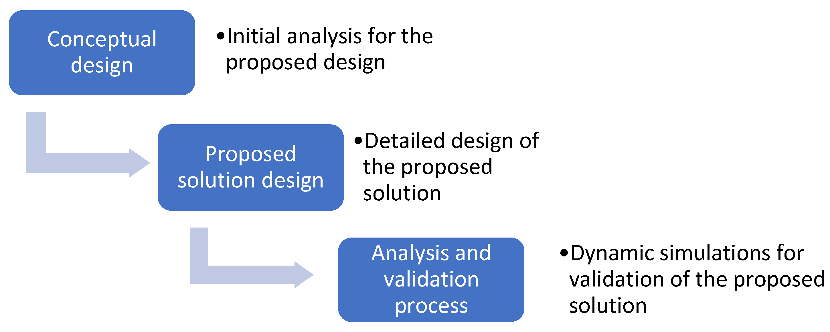
Figure 1 shows the proposed method for the design of the new turnout concept. We followed a three-step process. The first step consists of conceptual design, including defining the concept and its main features. The second step includes a detailed solution by defining and establishing the material specifications of the dimensions. The third step consists of the validation of the proposed design. For this purpose, several simulations focused on different situations were carried out. The results obtained were analysed in order to demonstrate the advantages of the proposed system.
3.1. Conceptual Design of the New Turnout and Its Viability
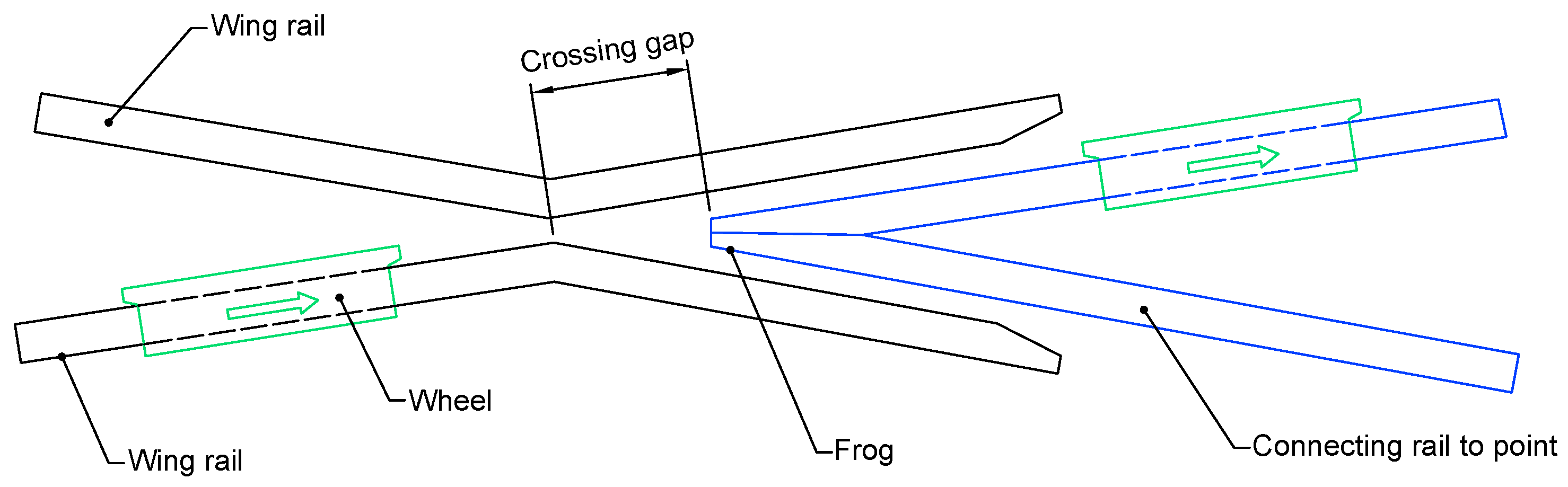
Figure 2 shows the usual configuration of a crossing, where a wheel can be seen passing through it. In a traditional crossing, there is a discontinuity of significant dimensions in the rail, called the crossing gap, which is often a source of incidents and accidents, and is one of the main causes of derailments in the critical area of the frog. In this respect, solutions have been developed to minimise this gap.
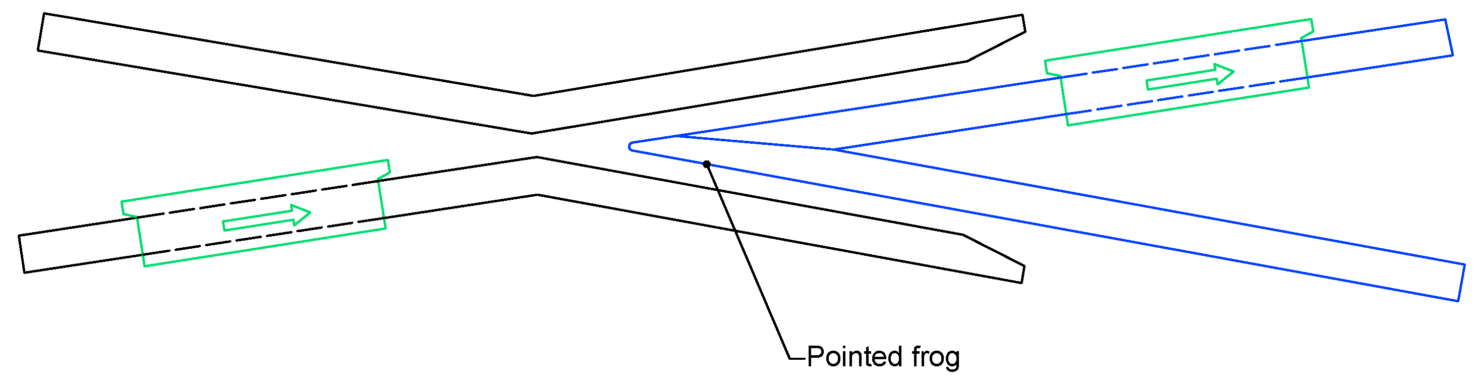
The most common is the use of pointed frogs [
24], as shown in
Figure 3. This type of solution reduces the gap, but it also presents some disadvantages, as the wheel passing through the crossing causes bumps in the discontinuity and eventually leads to wear of the frog nose. The green arrow indicates the direction in which the wheel is moving.
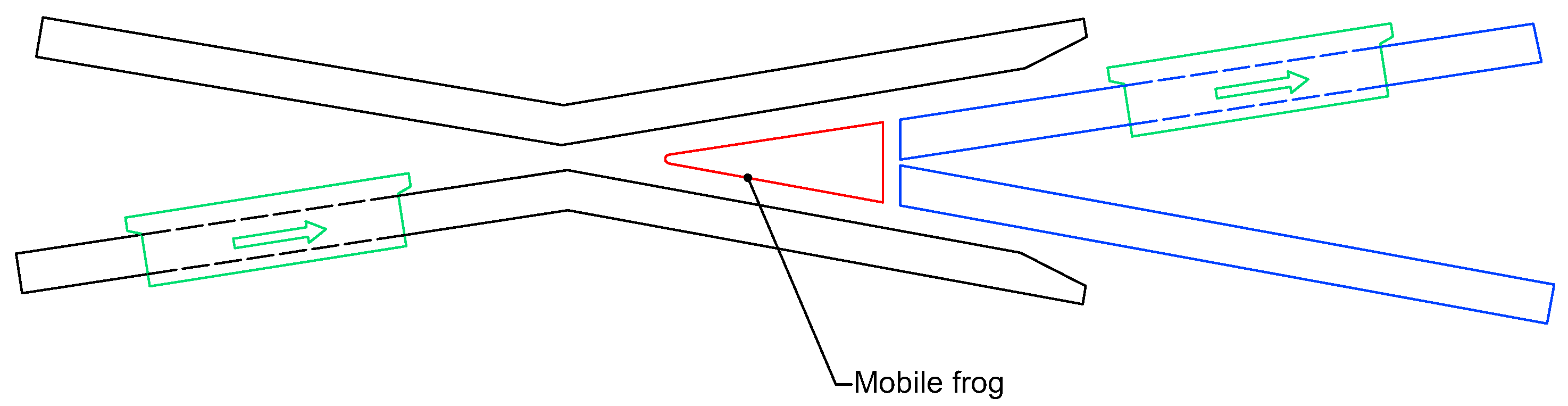
This work proposes the introduction of a new part, called a “mobile frog”, which is limited by the surface of the crossing, whose function is to allow the wheel flanges to pass through (
Figure 4). Through data collected from the different railway administrations, the spaces and dimensions were analysed in a CAD program to visualize the described results.
The proposed solution focuses on addressing the problem of collision of the active edge of the wheel flange with the frog nose. This problem occurs due to the descent of the wheel into the crossing gap as a consequence of the lack of support (or the total absence thereof) in the wing rails during its passage from the direct rail to the turnout.
The objective is, therefore, to complement the existing gap with a part of the same material (represented in red in
Figure 4), which is similar to the common crossing mechanism used in the area of the crossing gap, thereby also allowing for greater speeds, as it minimises the existing gap. Moreover, the addition of the proposed structure to this type of crossing is easy to realise, thereby increasing safety in the traffic of trains as they pass through it (
Figure 4). This approach also has the advantage that the mobile frog can be built with a higher-strength material and can be easily replaced in case of wear, without having to replace the rail.
This new part adapts, insofar as its dimensions, to the available space in the crossing gap to allow circulation in both directions of the track, which is denoted in railway terms as a “mainspring”. Initially, in a conventional turnout, the idea of reaching the mathematical point of the constructive railway was proposed, thereby contemplating an increase in the length of the real point of the common crossing. However, the final geometry is very fragile at the nose of the common crossing.
The advantage of the design objectives of this study is to optimize spaces, which allows for the construction of a slightly more robust part; however, the most important aspect to emphasize is that it is independent of the common crossing, such that its maintenance will be much simpler when it must be replaced due to wear.
Additionally, as the active edge of the flange can collide with the nose of the core when a wheel passes through a crossing section, this can lead to significant wear of the material. In this respect, the proposed solution has several advantages. On one hand, it is possible to replace the part without great difficulty, which will facilitate the machining of the active edge to avoid derailment, and on the other, the proposed solution makes it possible to align the position of the frog, thus compensating for the wear that occurs.
The geometric shape of the new part shown in
Figure 4 facilitates its manufacture and, therefore, reduces its cost. In addition, due to its independence from the rest of the rail, it is easy to replace and, therefore, incurs a low maintenance cost.
The proposed geometry provides a greater support surface than the current one, thereby reinforcing the consistency of the system and facilitating maintenance as a part of a smaller section; therefore, it is less expensive overall. This additional support surface within the surface delimited by the “wings rail” ensures a lesser descent of the wheel during its passage and, therefore, a reduction in the impact of the flange of the wheel that passes from the direct rail to the bypass on this surface. This reduces the risk of derailment and, therefore, permits passage at a greater speed.
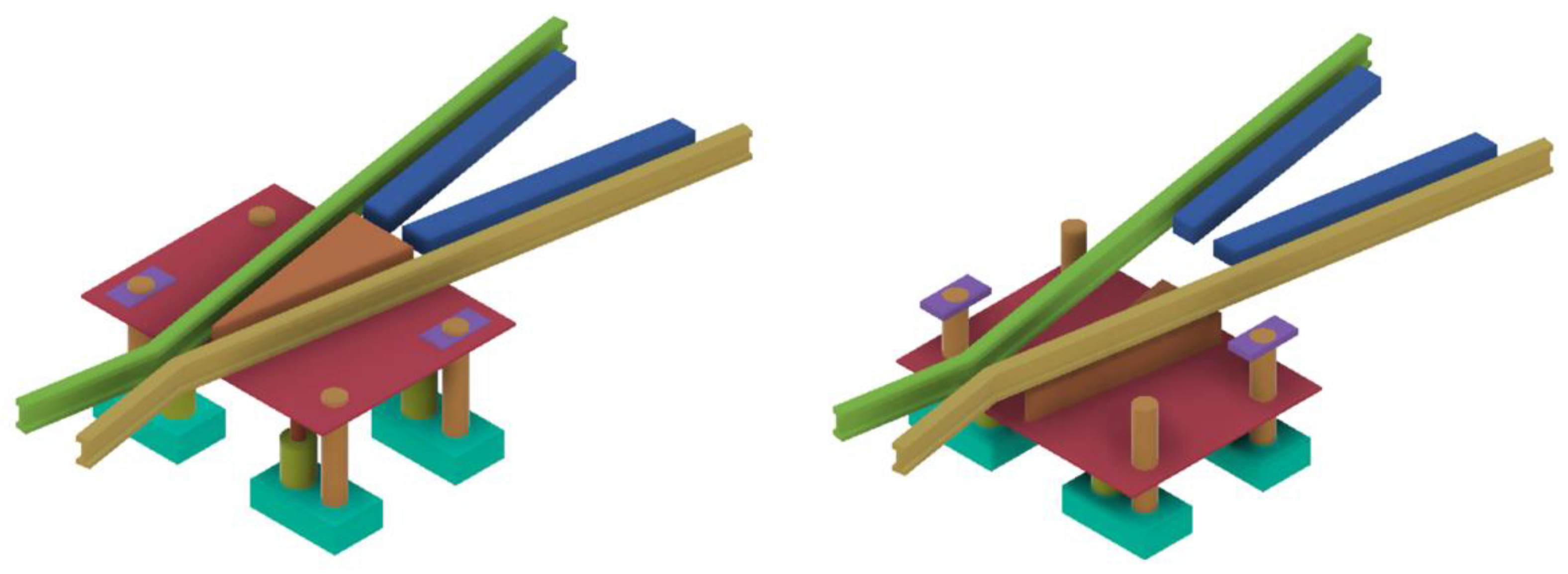
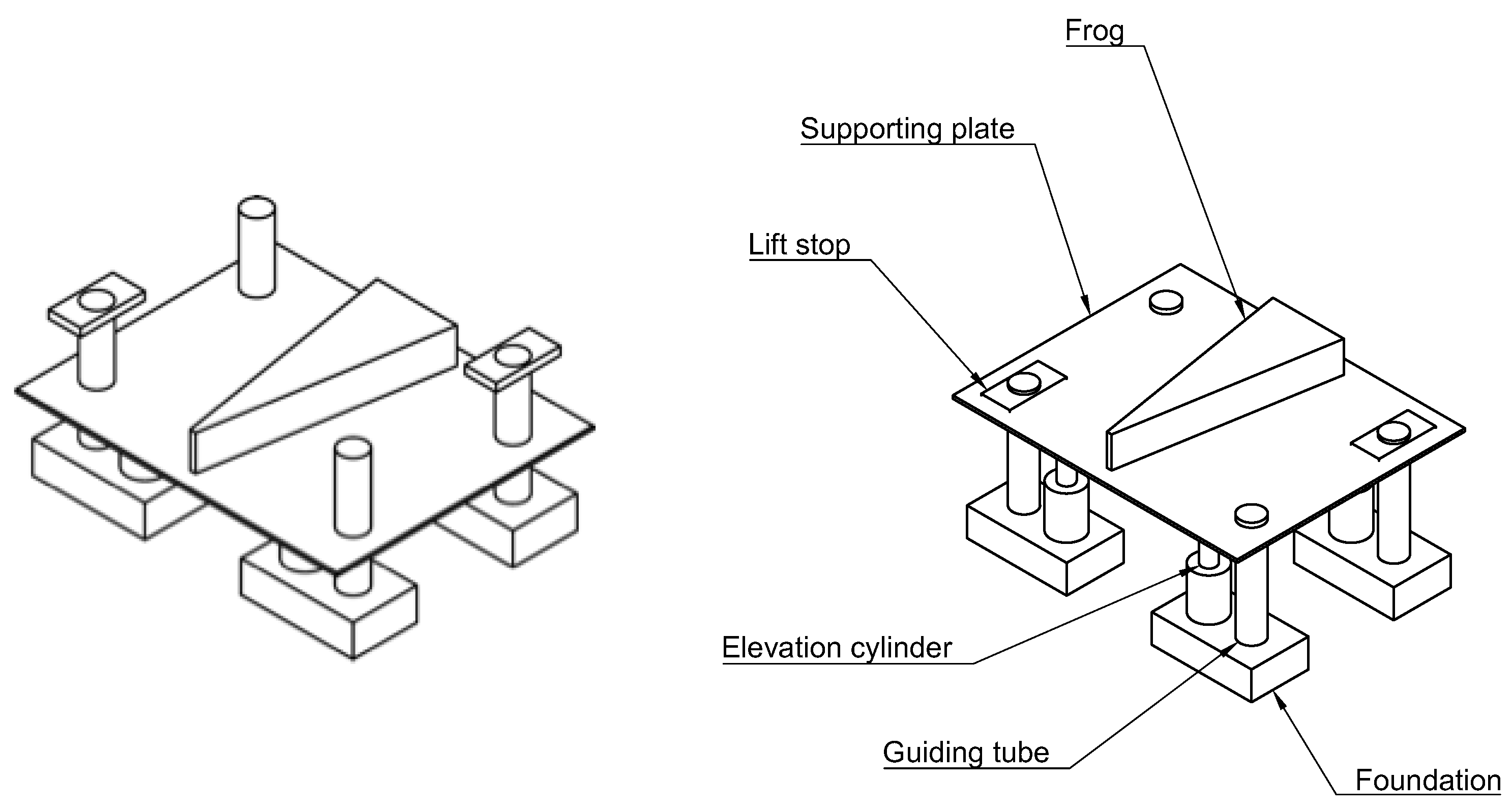
Figure 5 shows a scheme of the proposed design.
The part is not fixed in the frog but, rather, moves up and down using several elevation cylinders and motors, thereby facilitating its performance (as required by the wear of the rails), which is produced by the continuous passage of trains. The option of the use of motors to raise or lower the part provides greater accessibility for repair work and maintenance in the frog and its surroundings. Furthermore, its ascent solves the problem of alignment with the rails, thereby adapting to the irregularities caused by wear. For increasing safety in this regard, level sensors may be placed on both sides, which, when automatically controlled, serve to maintain alignment.
These movements in either direction, up or down, of the piston stroke, are performed at a programmed time triggered by the reception of electronic communication signals that will permit the train to pass and, thus, it may also be included in the European Railway Traffic Management System (ERTMS), a rail safety program which controls the appropriate distance of railway vehicles.
The installation of level sensors provides two advantages: firstly, it ensures the part reaches the desired position, using the reception of a similar signal from the computer of the train; secondly, it can lead to longer useful life, both for the rails forming the wing rails and the part itself.
This part is supported by a metal structure built for this purpose, consisting of a metal plate made of carbon steel. It is located where the part rests and, underneath it, there are four hydraulic cylinders that raise the plate along four tubes (guides), which are also made of steel. This metal structure is supported by a pre-cast concrete slab, and the punctual loads are supported by both metal and concrete structures. These structures must support the maximum weight per axle of 22.5 tons. This is the maximum weight per axle that can be loaded by different types of rolling stock.
Figure 6 presents the concrete structure and all of its components.
To simulate the effect of the passage of a train, a model was considered in two different situations: (1) a conventional turnout, and (2) a turnout based on the proposed model.
A series of models were developed, according to an ascending range of speeds, allowing us to maintain the reality of the data, according to the current technological state.
In this paper, we analyse the influence of the new constructive geometry for a turnout using a series of dynamic parameters. We examine the lateral force, which is the cause of derailment, as well as the perpendicular force on the track. Once these values are shown to influence the system, Nadal’s condition can confirm the data obtained, thus demonstrating the decrease in the risk of derailment—the object of this study.
3.2. Proposed Solution
Due to the large number of existing turnout types and their different dimensions, we decided to carry out the design exercise based on a single representative example; therefore, as the proposed part is variable, depending on the turnout, the model proposed was adopted in its construction to adapt to the characteristics of the other switch gears of which the turnout is part. The dimensions of the part were accurately calculated, in order to determine the space the part occupies in the crossing gap, without interfering with the passage of the wheel flanges. We also analysed the proposed part to observe its deformation as a train passes. The track gauge assumed in this paper was 1520 mm, and the turnout used for this project was type DS-C-54-318-0,9-CR-I. The meanings of terms of the turnout are described in
Table 1, while
Table 2 provides the mechanical characteristics of the rail UIC 54.
Regarding the design of the common crossing, two models were taken into account. The name of the aforementioned turnout was: HEAD OF CENTRAL BLOCK 54E1 Tg 0,09-CR9630 mm of LENGTH, where 54E1 denotes a UIC 54E1 rail in a special category with a greater linear mass and cross-section. The UIC 54 rail has the mechanical characteristics described in
Table 2. The height of the common crossing is 160 mm; thus, the part must be taller than this to reach this height from the proposed plate, which is below the level of the common crossing. Therefore, this additional height was estimated to be 20 mm, providing a certain margin to compensate for its wear.
With all these hypotheses, a static analysis model was developed, thereby determining possible fragility, in order to determine whether it can support the weight of the train either without deformation or with permissible deformation.
3.3. Dynamic Analysis: Simulation
3.3.1. Introduction
For this simulation, the Universal Mechanism software [
25] was used. This program allows the simulation of the dynamics of rail vehicles through differential-algebraic integration of motion equations, which is considered necessary to obtain the required results. With this tool, the passage of different types of vehicles, such as bogies, axles, and bogie or axle wagons, as well as complete trains, may be simulated. In addition, it allows for modification of the geometry of the route, determining whether it is straight, curved, or has a turnout. Introducing new parameters allows us to calculate the different forces and parameters affected by train dynamics during the selected route.
For the dynamic model, we considered a rigid axle 3D model and the track geometry, including the turnout geometry.
3.3.2. Parameters of Turnout
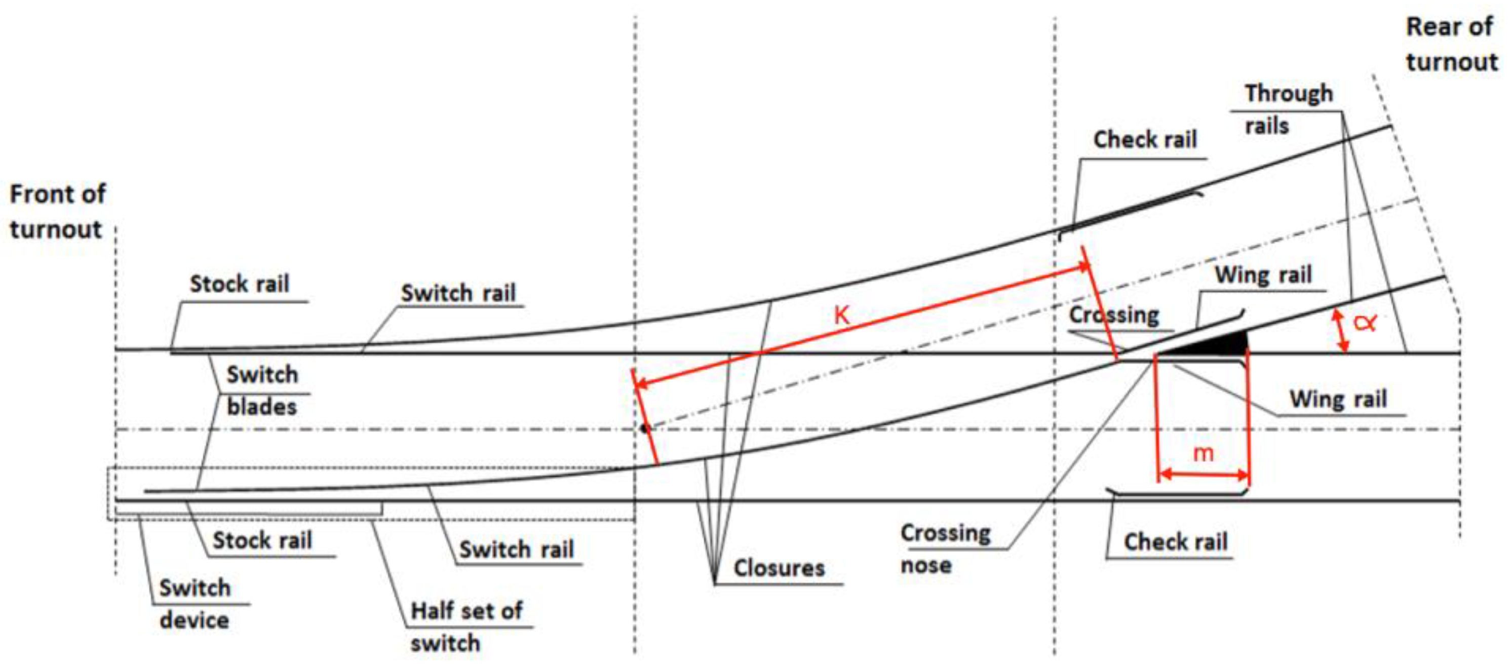
The turnout presented in
Figure 7 allowed the program (in which the different parameters are introduced) to conduct the required simulations for both conventional and new turnouts. This is composed of a simple turnout with a direct and a bypassed road, which is the most common type found in most of the railroad tracks in Spain and the rest of Europe.
Figure 7 shows the main turnout parameters. From the parameters displayed in
Figure 7, we selected those that the program requires to define the geometry of a turnout. The meanings of these parameters are detailed in
Table 3.
Two parameters are expected to undergo some variation, concerning the current state of technology. One is the length of the crossing gap (m). By varying this parameter and keeping the turnout length constant, the gap can be lengthened in the area of the crossing gap, which is the object of this innovative work. The other is the tangent section before the common crossing (K). This will necessarily change when varying the length of the crossing gap since, as this increases, so does the wheel–wheel contact at the bypass. To keep the radius of the turnout constant, we increase the tangent section of the common crossing, in a manner equivalent to what would be an increase in the length of the common crossing, and a corresponding comparison was made to study the results.
We observed that, by varying these two parameters, the results were very similar to those that would have been obtained when using the CAD design for the constructive part of the turnout design.
3.3.3. Parameter Comparison in Conventional Turnouts
When calculating a deviation, the radius of the curve of the deviation must be determined. The meaning of these parameters is shown in
Table 4.
For this, approximate values of non-compensated lateral acceleration (a
nc) must be handled by acting on the passenger. These values are regulated, such that they do not affect the comfort or safety of passengers. A valid value for this parameter is 0.65 m/s
2. The method for evaluating ride comfort is based on the EN 12299:2009 standard [
26].
In addition, the maximum speed (V) foreseen for the circulation in the track is known. With these data, the radius (R) of the turnout can be obtained from the expression:
The geometric shape presented in
Figure 7 also facilitates its manufacture and, therefore, reduces its cost. In addition, due to its independence from the rest of the rail, the proposed part is easy to replace and, therefore, has a low maintenance cost.
The usual values used for turnouts are shown in
Table 4. In our study, we consider a 1:13 turnout.
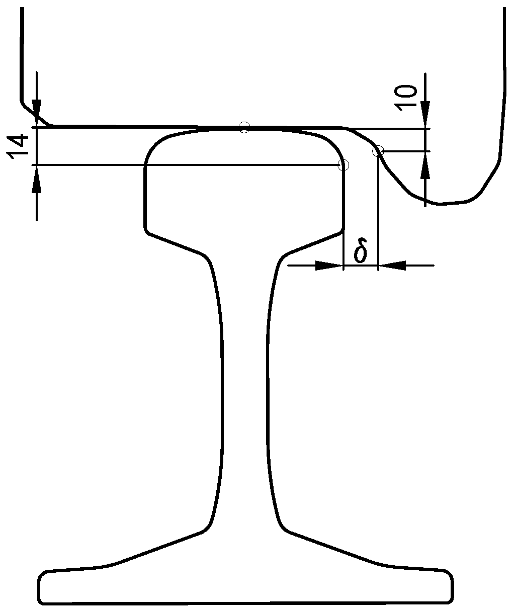
It is also necessary to determine the contact (δ) between the wheel and the rail. The rails used in the described turnout stand upright and the track dimensions are measured 14 mm below the top edge of the rail, while the vehicle dimensions are measured 10 mm below the top edge of the rail, as shown in
Figure 8.
The corresponding calculations were determined by the following expressions, including calculations for the wheel unloading rate, when a vehicle passes over the proposed crossing, following the scheme shown in
Figure 9.
where
and
where a is the wheelbase of the rails.
For h << a, cosβ = 1 and sinβ = β.
Therefore, we can deduce the maximum speed to be:
where a
nc is the non-compensated acceleration. In the modelled turnout, we set h = 145 mm.
3.3.4. Parameter Comparison in New Turnouts
The reference for the turnout used for the study is shown in the upper part of
Table 5, and the previously defined parameters (as well as their values) are shown at the bottom of the table. The only resulting variations corresponded to the total length of the common crossing (or common crossing length). For the conventional turnout, a length of 3500 mm was chosen, while a length of 4000 mm was used for the new turnout, as a result of extending the nose of the crossing (PR) to the theoretical intersection point of the crossing (PM).
Table 5 provides the values of the parameters for the proposed turnout in the simulation.
4. Results
4.1. Simulation Results
The results of the simulation applied to the designed crossings are presented in the following section based on the front bogie of a freight car. First, we cite the referenced parameters on which comparisons were made for different common crossing lengths. Then, the results of the simulation are provided, using the largest resulting tangent section for a particular radius variation. The comparison was done for two different speeds: 40 and 60 km/h. The distance between the axles of the bogie was 2500 mm.
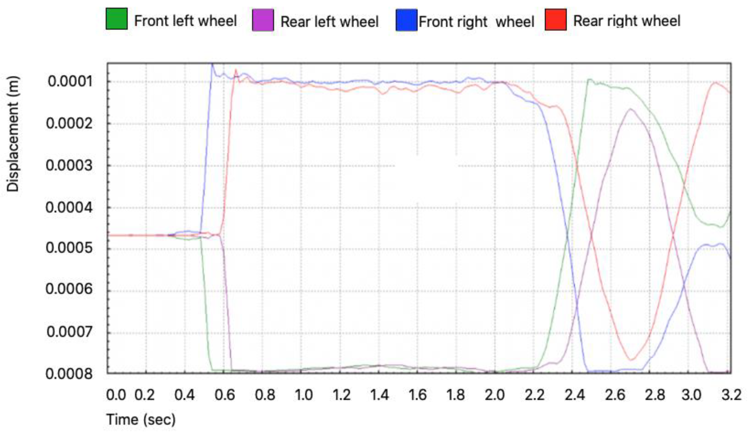
4.1.1. Location of the Centre of Mass on the Z Axis
In
Figure 10, the time (in seconds) is shown on the
x-axis, and the corresponding displacement on the ordinate is expressed in meters. Thus, in the first section of the turnout, arising from the absence of support on the left section up to 0.5 s, the train runs straight without unevenness of the track. As a consequence, the centre of mass on the
z-axis of the four wheels is approximately at the same height. From this point, in the case of a circular turn (the axis of which is to the right), the left wheels must rise, while the right ones must descend, due to the centripetal force and the moment it provokes. We observed that, at approximately 2.5 s, a variation of the tendency in the turn appears as the road begins to change towards the original straight direction, especially when coming closer to the arrival of the front wheel to the left of the crossing gap. Due to the lack of support, the passage of the wheel from the direct road to the deviation occurs, and it descends on the crossing gap, thereby causing a drop in the centre of mass. The right wheel, therefore, presents similar behaviour. The same behaviour occurs at the back wheels on both sides.
4.1.2. Friction Resistance
The resistance to lateral friction was obtained to explain the operation of the turnout and, in particular, to demonstrate that the presented turnout corresponds to the physical variables obtained from the program. The lateral friction corresponded graphically to the behaviour of the bogie as it passes through the turnout, thereby obtaining the results for each of the four wheels of the bogie.
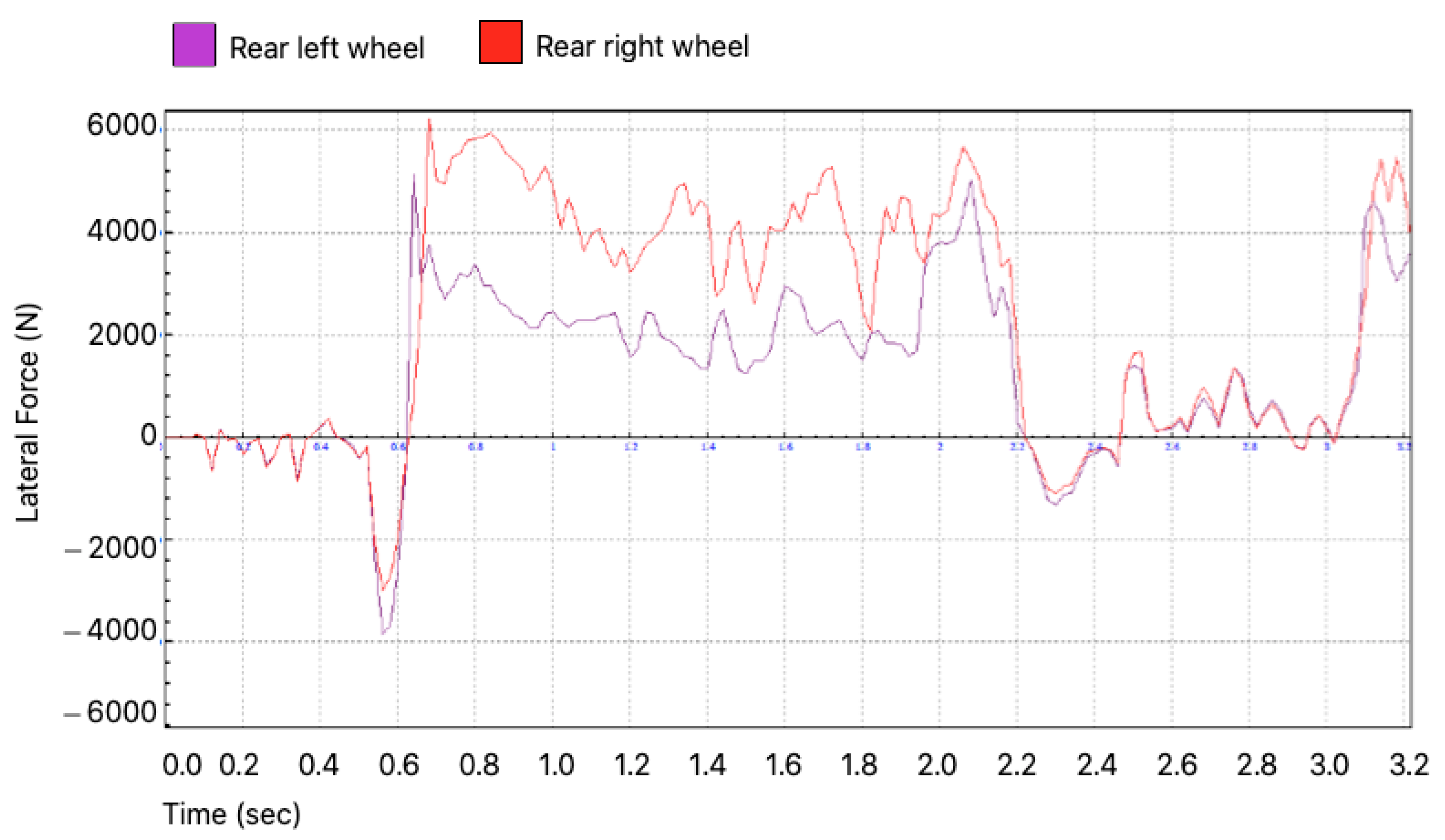
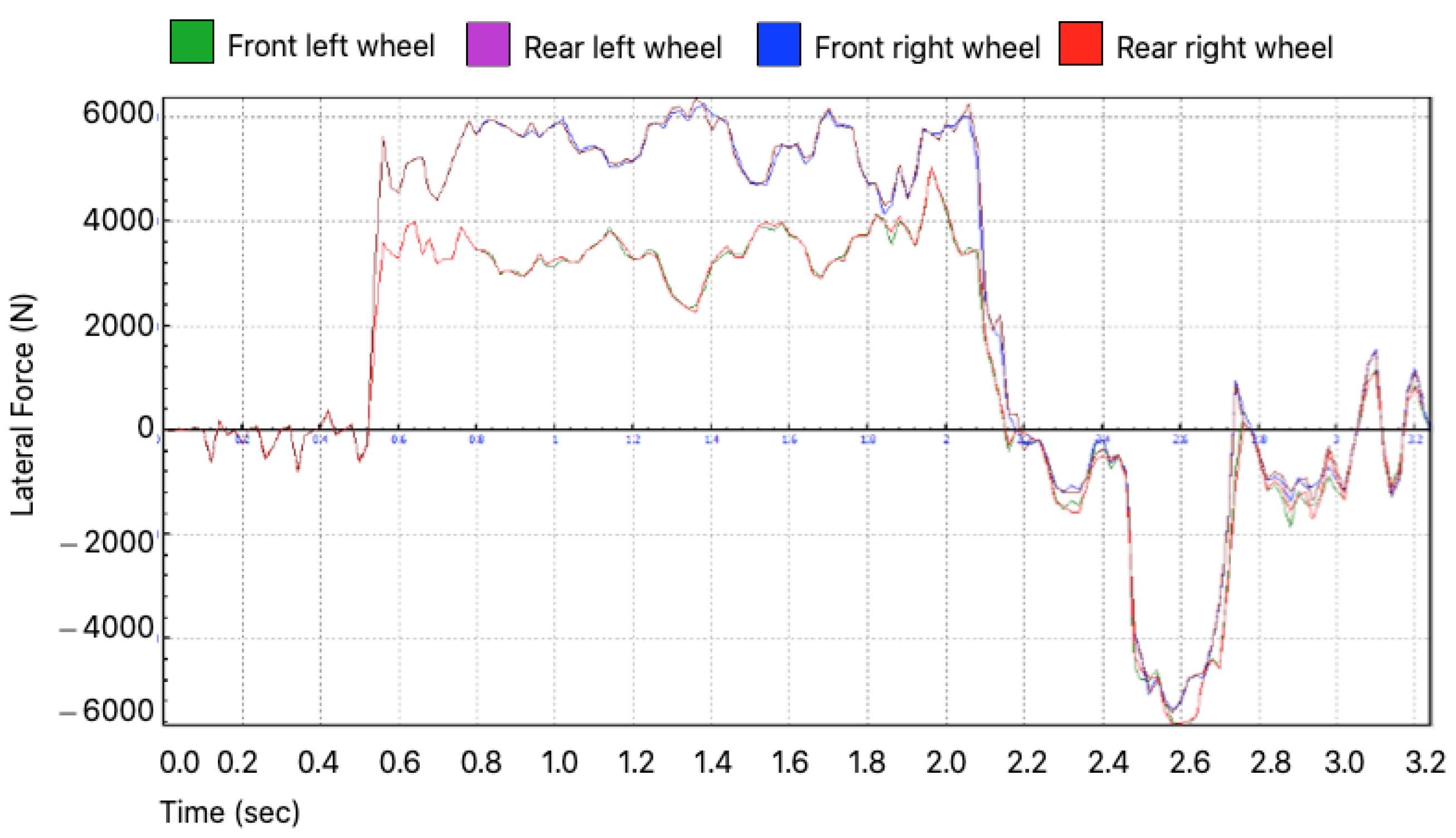
Figure 11 and
Figure 12 represent the total friction in the two front wheels and the two rear wheels, respectively, of the bogie in a conventional turnout and with the proposed crossing.
Green and blue are used for the left and right front wheels (
Figure 11), and purple and red are used for the left and right rear wheels (
Figure 12), respectively. Another relevant factor in this plot is the 300 m radius of the turnout, as well as the common crossing length of 3.5 m and the speed of 60 km/h. The progress of the bogie, represented by the lateral force of friction on the wheels, may also be observed.
Up until 0.5 s, the bogie displays a straight trajectory before the turnout. The simulation occurs from this point until 2 s when the bogie is inside the circle of the turnout and close to the common crossing. The rotation is to the right, and we observe an increase in the force of friction due to the centripetal force that pushes the flange against the rail. After 2 s, the bogie enters the common crossing and returns to the straight path, thereby experiencing less lateral friction force. It is at this point that slight increases in the various forces take place in the different sections as a consequence of the movement, which is typical of rail movement. We observe behaviour identical to that explained above. In general, it was observed that the rear wheels were less requested; that is to say, the load they experienced was smaller than that which occurred on the front wheels.
4.1.3. Lateral Force on the y-Axis
Finally, we present the comparison of the conventional turnout at different speeds, in order to observe the lateral force of friction and to be able to demonstrate that the friction forces decrease at a slower speed, even when only decreasing to 40 km/h (
Figure 13). We observed that, by slowing down the bogie, it still passed through the same logical states, but with a certain justified delay.
In conclusion, the proposed simplifications did not affect the objective results of the remaining simulations. These are characterized by logical reasoning and expected behaviours, thus producing results in line with those explained previously.
This force occurred as a consequence of the lateral displacement experienced by the bogie in its passage along the track due to the centripetal force due to the train turning. Therefore, it is considered a fundamental value in this study, as it is the total effort supported by the wheel when in contact with the common crossing. The proposed new version of the crossing should minimize the effects of the impact of the flange of the wheel on the nose of the common crossing, as a new part is added that reduces the descent of the wheel in the common gap.
At the simulation point, we reach the common crossing. There is an increase in the lateral force as a consequence of the collision of the wheel flange with the nose of the frog, after the descent of the wheel into the crossing gap. More effort is supported by the right wheel, due to collision with the rail. The rear wheels undergo less effort as the bogie is already centred and aligned on the rails of the deflected track.
There is a smaller decrease in the lateral force for the maximum value in the left wheel, but there is considerable improvement before the subsequent collision. Therefore, it follows that both the lengthening of the nose of the common crossing towards the crossing gap area and an increase in the length of the tangent section before the crossing—the characteristics of which are similar to the behaviour of that new design—lead to a reduction in the maximum lateral force experienced at the moment of impact of the wheel with the nose of the common crossing, which is reduced in the lane opposite the crossing. At the same time, a reduction in the lateral effort was achieved in the wheels that come into contact with the common crossing. Although they are smaller, the dynamic improvement is distributed in the sections before and after the impact.
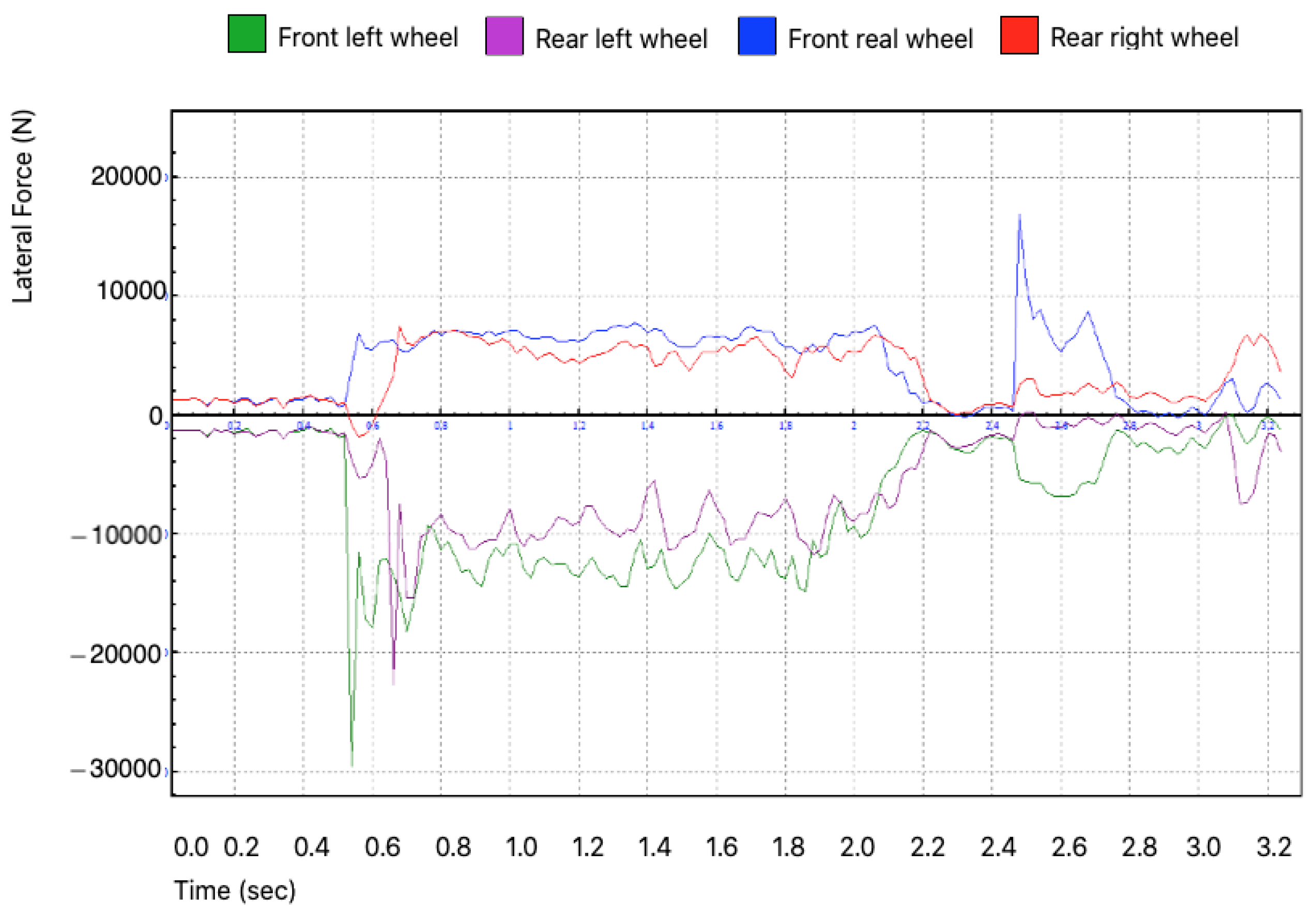
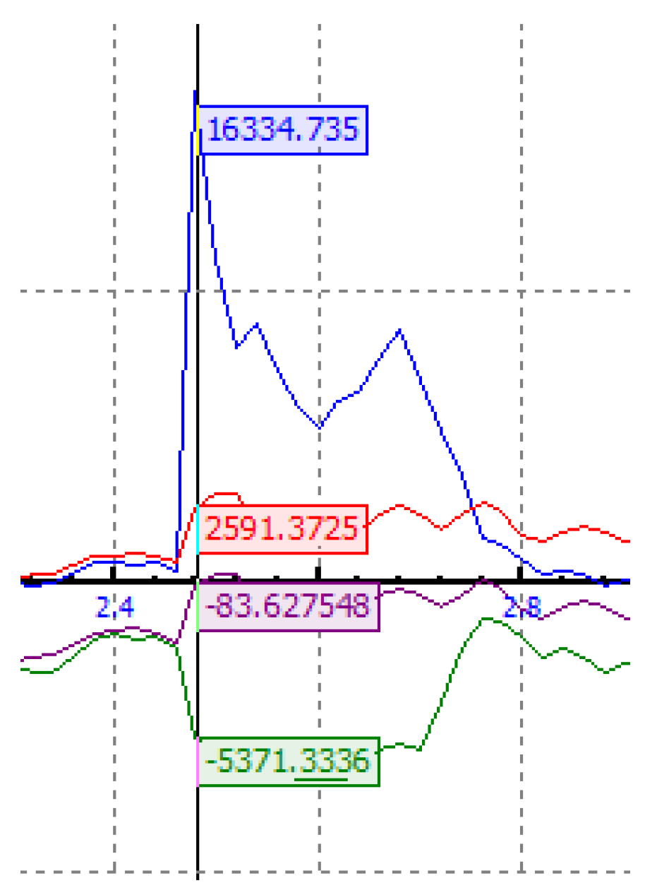
4.1.4. Lateral or Transverse Force on the y-Axis
Transverse force occurs as a result of the lateral displacement suffered by the bogie in its circulation along the track, as well as due to centripetal forces or the movement of the train itself. It is a key value in this project, as it describes the total lateral force suffered by the wheels on contact with the common crossing.
The development of the new turnout should soften the effects of the collision of the wheel flange with the point of the common crossing, as a piece has been introduced that reduces the descent of the wheel into the crossing gap (
Figure 14), and the value (in Newtons) of the peak resulting from the flange–common crossing collision can be seen in
Figure 15.
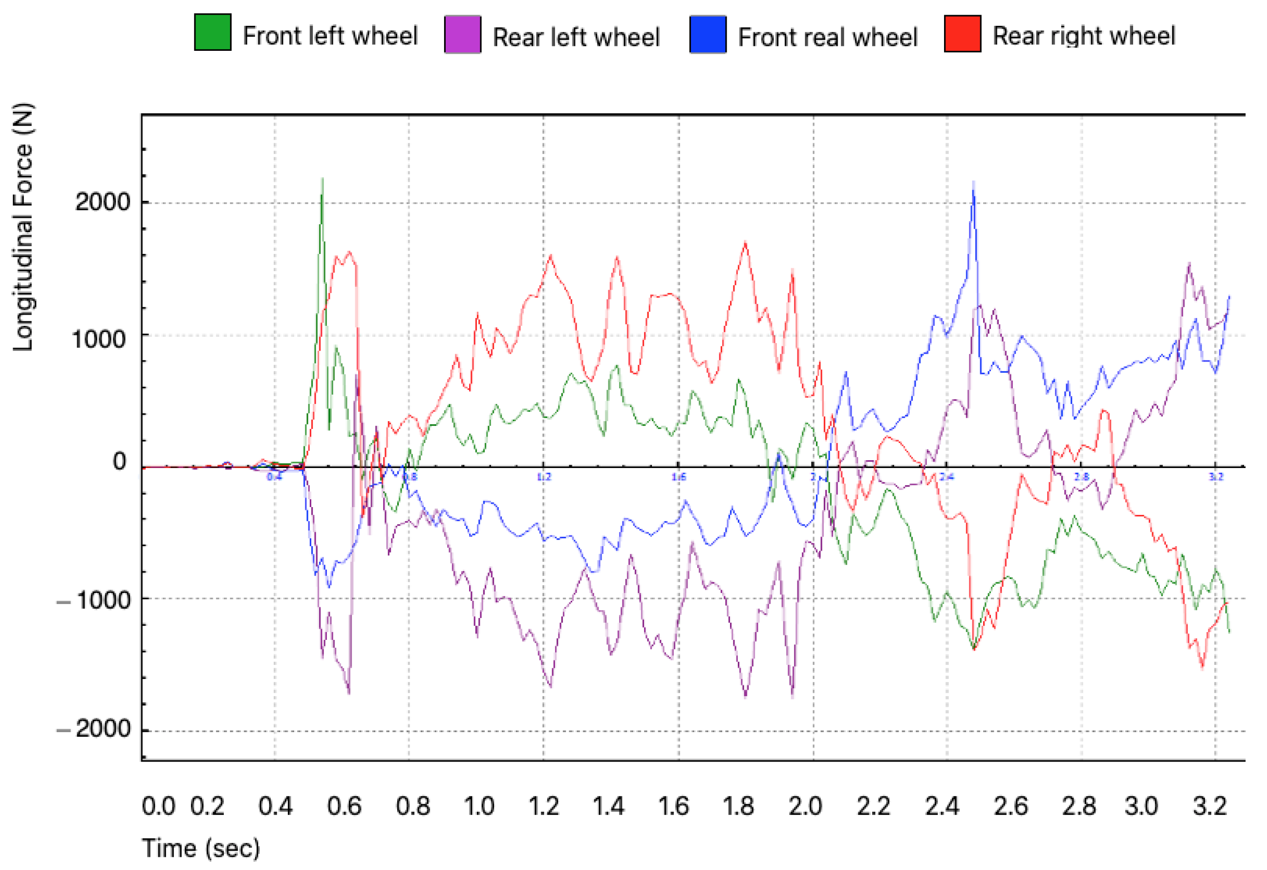
4.1.5. Longitudinal Force
The longitudinal force (
Figure 16) during the straight section (up to 0.5 s) has small values (on the order of hundreds). From this point forward, as a consequence of the flange–rail contact in the turn, the force picks up after 2000 N in the left front wheel, while a similar pick-up also occurs in the rest of the bogie wheels. In the time span from 0.5 s to 2.5 s, during the contact of the flange with the rail due to the 300 m radius turn, the longitudinal forces stabilize around 1000 N. Upon reaching the crossing gap at 2.5 s, a rebound occurs, as a result of the wheel–gap shock described in this work. Subsequently, the value stabilizes at smaller values and is only altered by the slight shocks typical of the straight-line loop movement in the circulation of rolling stock.
It can be seen that the results were as expected for the chosen crossing and chosen route. Compared to the lateral force, it is clear that it is much less important and that the left part of the bogie suffers more longitudinal force, contrary to the situation of the lateral force.
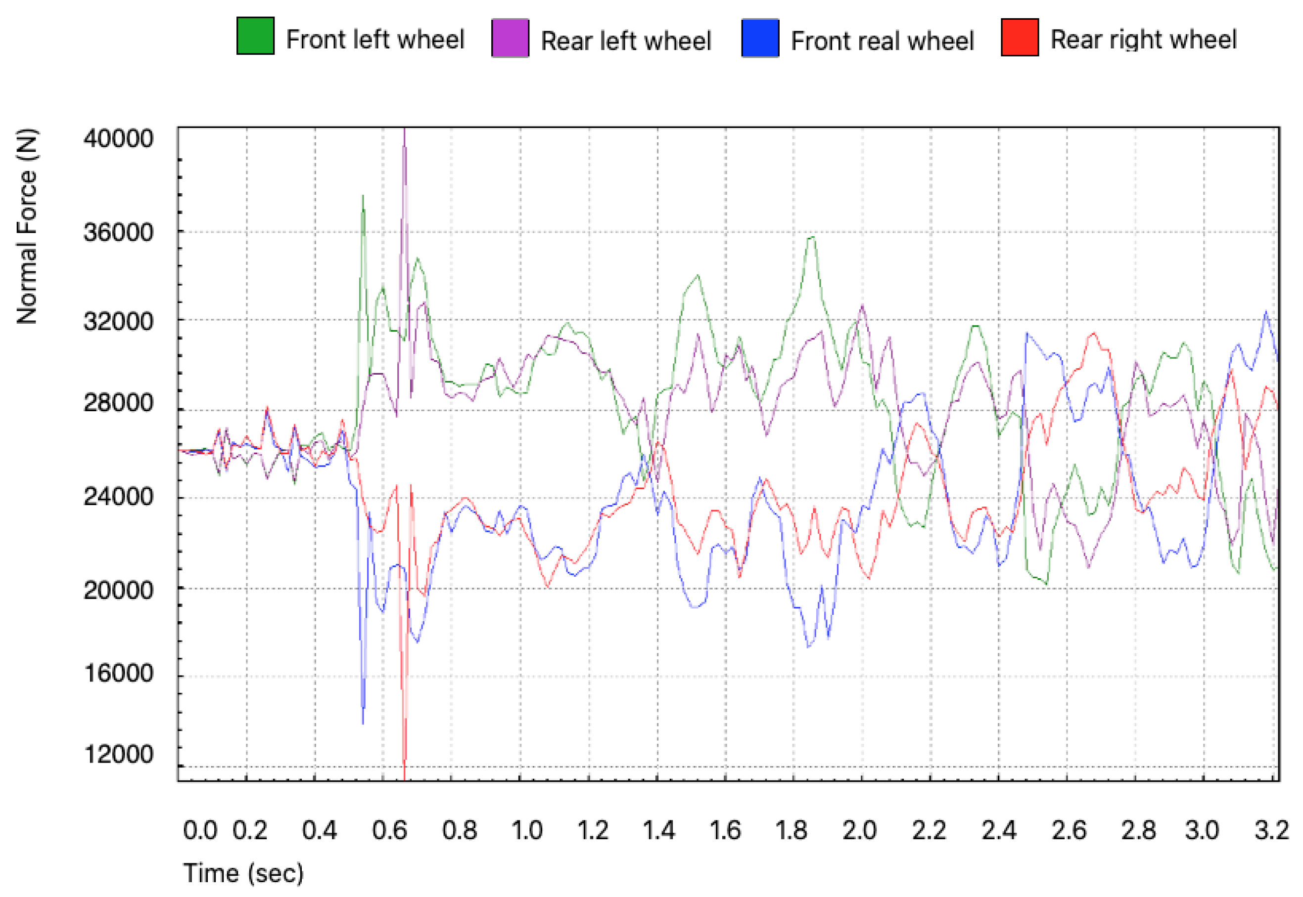
4.1.6. Normal Force on the z-Axis
Figure 17 shows the force exerted by the rail against the wheel as a result of the reaction of forces. This is a useful parameter to explain how the possibility of climbing is reduced when introducing a piece that softens the collision of the wheel flange with the point of the crossing gap. Despite their similarity in terms of maximum values, the graphs can be seen to be different, as the behaviours of the forces differ. The first difference is at the beginning of the graph. The force does not start at the value associated with zero on the graph. This seems logical, as a positive normal force is always expected, even if it is the beginning of the movement and in a straight line. Therefore, while the lateral stress graph starts at zero due to a straight circulation at the beginning, the value of the normal stress is evident from the first moment in the simulation. From 0.5 s onward, a similar rebound is produced, which differs in the absolute value of the force but is very similar in differential jump (around 20,000 N). From this instant of time, the graph stabilizes at around 30,000 N. In the case of lateral force, this equality in value does not occur over such a long time, suffering a rebound when it reaches the heart of the deviation. A slight decrease in the normal force can be seen around 2.2 s, due to the lack of support of the wheels in the crossing gap.
Thus, we concluded that the new proposed deviation does not provide more than a slight reduction in the normal force supported by the wheels; however, it does provide an improvement and, therefore, the behaviour is not worsened. Having analysed the normal and lateral forces, Nadal’s criterion could be used to finalize the results of this simulation.
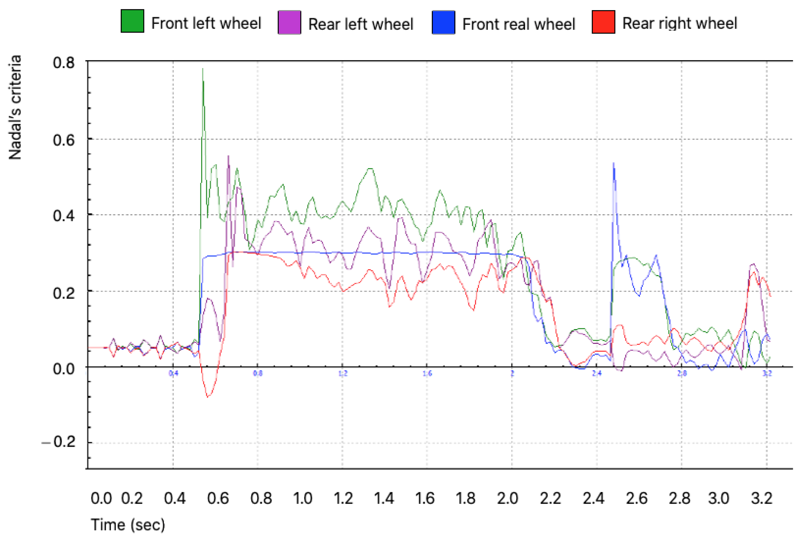
4.1.7. Nadal Criterion
Nadal’s criterion relates the vertical and lateral forces—which were analysed previously—in order to determine the real possibility of a rise of any of the wheels of our bogie. Therefore, although a consequence of the calculations shown above, thanks to this criterion, it is possible to analyse whether the probability of uplift has been reduced in the gap area in a simple manner, which is the priority objective of this project. If the vertical force is greater than the lateral force in the wheel–rail contact, Nadal’s criterion will be less than one, and, therefore, it is a safe zone. Nadal’s criterion is one of the most conservative in the field of railway derailments. The calculation of Nadal’s criterion is as follows:
where
δ is the angle when the wheel flange is in contact with the rail face,
μ is the coefficient of friction,
Y is the lateral force, and Q is the vertical force. As shown in
Figure 18, until the bogie begins to take the curve (with a radius of 300 m), the Nadal criterion is centred around 0, as a consequence of the low risk of derailment on the straight. After 0.5 s, the bogie is inscribed in the circumference of the turn itself, such that its lateral force and flange–rail contact increase, with Nadal’s criterion shooting up to almost 0.8. This is the highest value and, therefore, indicates where there is a more theoretical risk of derailment. Due to the construction characteristics of the crossing, although Nadal’s criterion is high, if the speed is adequate in this section, derailment should not occur. During the turn, the values of the criterion stabilize around 0.4—a reasonable value representing a low risk of derailment. Before facing the gap space, as a consequence of the straightening of the road, the lateral effort is again reduced and the value of Nadal’s criterion decreases. As around 2.5 s, once the left front wheel has passed the gap and has lowered the height of its centre of mass as a result of the lack of support, a jolt occurs that increases the risk of derailment to the surroundings to 0.6, in terms of Nadal’s criterion. This jerk can be explained as due to an increase in lateral force and, as in the graph of this effort, it is shown that the risk of derailment, due to a greater lateral force, occurs in the other front wheel rather than the one on the check rail.
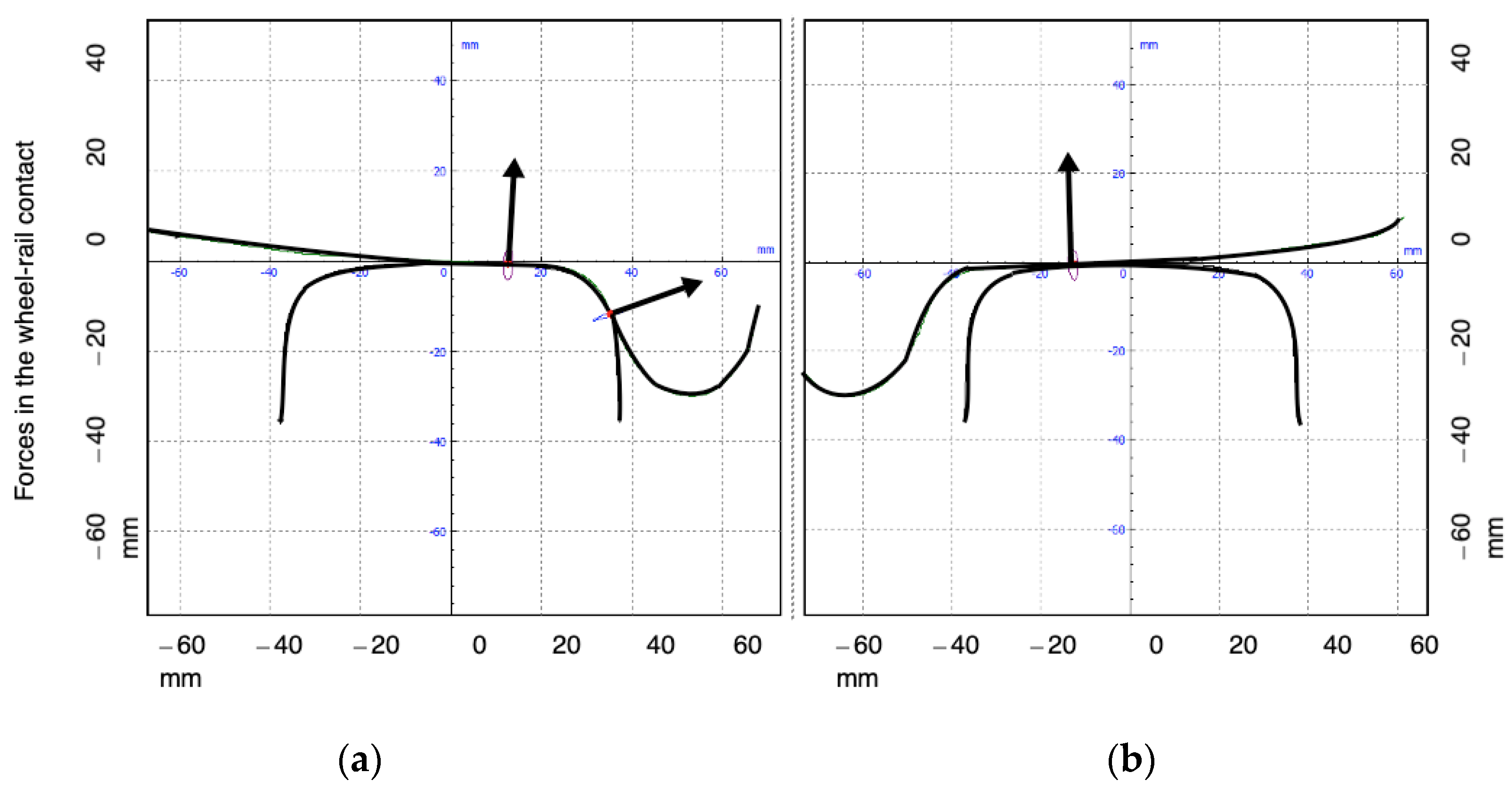
This can be explained by the wheel–rail contact and, therefore, by the forces that are produced as a result of this contact (
Figure 19), marked as arrows in the figure. Two scenarios can be distinguished. As can be seen from the analysis of Nadal’s criterion during the right turn in
Figure 19a, prior to crossing, the risk of derailment is greater on the left wheel, which is in the path of the gap. This is due to the rotation of the train, which moves the assembly to the left (b) as a result of the centrifugal force. As it is a right turn, the flange of the left wheel comes into contact with the face of the rail, acting as a stop, which increases the lateral force. The right wheel, as a consequence of the right turn and its displacement, is in contact only with the tread, highlighting the vertical component of the supported force. The results were similar for the front and rear axles.
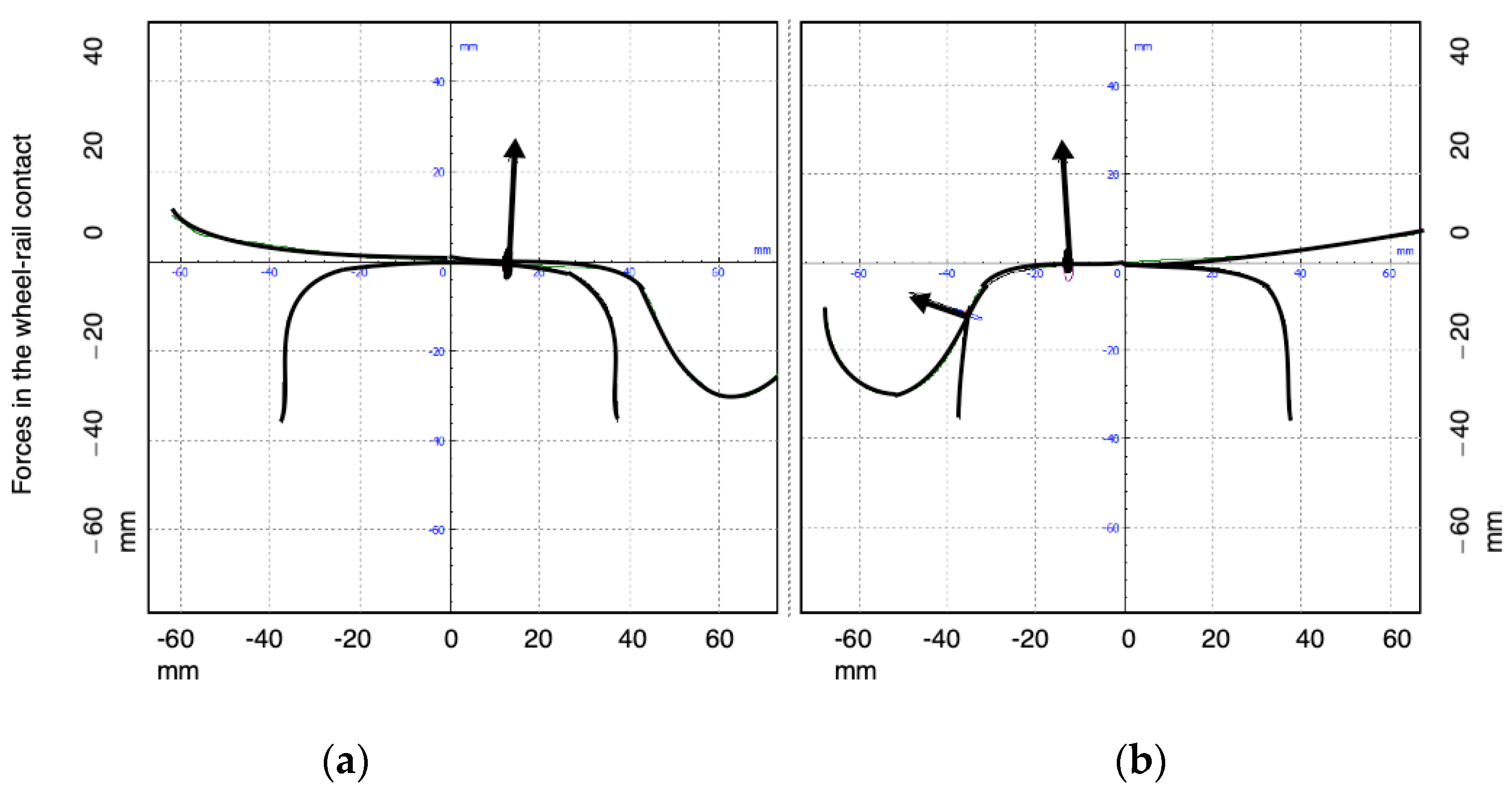
However, when it crosses the intersection (
Figure 20), the wheel that compromises safety due to a greater risk of derailment is the wheel that circulates along the rail outside the turnout (b), along the check rail. This element is responsible for preventing the displacement of the wheel as it passes through the crossing and collides with the gap, potentially causing derailment. Therefore, this wheel, being in contact with the check rail, increases its horizontal load.
It should be noted that efforts to reduce the impact with the nose in the common crossing not only improved the dynamic behaviour of that area but also led to a more pronounced improvement in the opposite wheel. Again, the most characteristic and interesting values to explain the dynamic improvement were observed for the front wheels.
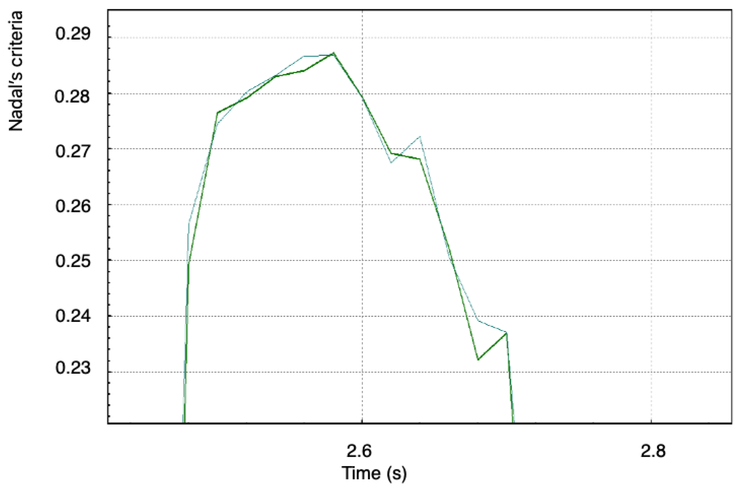
As explained, the Nadal criterion presented a reduction as a consequence of the elongation of the point of the gap, and the most interesting values were observed in the right front wheel, which passes between the right rail and the check rail. For both wheels, the risk of derailment was reduced, as indicated by a 6% decrease in the Nadal criterion (
Figure 21).
4.2. Structure and Analysis
4.2.1. Introduction
The design of the proposed solution was shown in
Section 3.1,
Figure 6. It is based on a metal structure responsible for lifting the designed part. It is also metallic and made from the same material as the conventional common crossing. It is essentially a prolongation of the common crossing, although with different dimensions. Once this movement is aligned with the covering of the crossing gap, it prevents the wheel in transit from being able to descend, due to the smaller support in the wing rail, as it advances towards the turnout. The punctual weight to be borne is 22.5 tons (this value is derived from the load on the wheel of the vehicle). It is advisable to keep the structure elevated as the train passes, and it should be raised according to the conditions of the rolling stock. Thus, for reduced speeds, such as those of a freight train, the part should be held in the rest position to reduce the corresponding wear; that is, it should only be used for trains at high or medium speeds, thus improving their safety.
This part is supported by a metal structure built for this purpose, consisting of a metal plate where the aforementioned part rests, four hydraulic cylinders responsible for raising the plate, and four guide tubes for guiding the plate. The metallic structure is supported by a continuous concrete slab foundation.
4.2.2. Materials Employed
The part proposed in this study is the most requested dynamically from the turnout, as it replaces the nose of common crossings as the first element that meets the flange of the wheel as it passes through the crossing gap in its trajectory. This, by itself, will reduce pressure. To achieve less wear and, therefore, reduce required maintenance, the part should be constructed of a material that ensures resistance to wear at a permissible cost. Such materials range from monobloc steels to manganese and should be manufactured in a single part without bolted joints, molded and manufactured entirely in Hadfield steel (Mn 12/14%), and subjected to heat treatment in a gas oven and cooling in a pool.
Mangalloy (also called manganese steel or Hadfield steel) is a steel alloy containing approximately 13% manganese on average. It is well-known for its high impact strength and resistance to abrasion once in a work-hardened state.
Mangalloy is made from alloying steel containing 0.8–1.25% carbon and 11–15% manganese. It is a unique, non-magnetic steel with extreme anti-wear properties. This material is very resistant to abrasion and is capable of achieving up to three times the hardness of its surface under impact, without experiencing any increase in brittleness which is usually associated with hardness. This allows it to manually retain its toughness. Both hardness and ductility reach their highest points at approximately 12% manganese, depending on other alloying agents. Due to these outstanding features, it can be considered an adequate material for common crossings and railway switches.
As a result, a part with great versatility in various applications (high speed, conventional, tram, load, and so on) can be acquired, which barely requires maintenance throughout its lifecycle.
4.2.3. Static Tests
Given the great need for precision regarding the location of the part at the moment that the train crosses it, it is necessary to ensure that the part is placed in its exact position. This can be achieved through the use of sensors. It is also necessary to ensure that, during the passage of the train, the part does not deform more than the plate that supports it.
An analysis was conducted to study the effects of these two aspects, as Von Mises stresses regarding structure failure theory, and elastic failure criteria, which allows for the establishment of different approaches with respect to the materials to be used, thus allowing for appropriate design.
5. Discussion
After successive analyses of the simulations applied under different parameters, it follows that, by applying the values of the common crossing length and turnout radius to simulate the conditions of a turnout, and the crossing gap, with the presence of an additional body, the undesirable dynamic effects of the passage of a freight wagon bogie or a passenger car could be achieved.
Therefore, one of the consequences of the results drawn from the conceptual design of the turnout is a reduction in the wheel’s descent as it passes through the crossing gap. This arises from the greater support surface and is provided by the proposed part in combination with the existing surface; that is, the nose of the check rail. As a result of the lowering of the wheel at the previous point, the shock produced by the active flange of the wheel with the nose of the common crossing is softened by limiting the lateral force. For the conditions under which the simulation was performed, the lateral force was reduced by approximately 100 N, demonstrating a significant improvement in the dynamic behaviour of the vehicle, leading to a lower risk of derailment and greater traffic safety. Furthermore, under less lateral stress the parts will be less requested and, therefore, the maintenance costs will be lower.
The perpendicular stress experienced by the wheels can also be reduced, to a lesser extent, but the maintenance of a lower risk of derailment is positive, especially considering the decrease in lateral force shown in the simulation, based on the Nadal criterion. The supported longitudinal force was also reduced, implying better dynamic behaviour. This decrease was approximately 300 N.
Finally, Nadal’s criterion, which is related to the lateral and normal forces to determine the risk of derailment, confirmed the obtained results. The decrease in this value in the environment of the common crossing indicated a decreased risk of derailment, as demonstrated in the plots shown, due to the reduction in lateral effort, with the value decreasing from 0.53 to 0.49, comprising a decrease of 7.6%.
The main objective of this article was to increase the safety of railroad turnouts, thereby reducing accidents due to the derailment of trains as a consequence of the re-mounting of the wheel on the rail.
As the crossing gap in the line is treated as a point of discontinuity, it involves a special dynamic behaviour and, therefore, is problematic for the safety of both the traveller and the rolling stock. Therefore, it is necessary to carry out a study of these characteristics to reduce accidents as much as possible.
As demonstrated in both the conceptual design and the simulation, the proposed objective was achieved by improving upon existing technology, in an effort to increase the surface of the wheel as it passes through the crossing gap. This means ensuring that the wheel does not fall into this space due to a lack of support, as well as improving the comfort of passengers when crossing the switchgear.
This new design also optimized the space that the crossing presents in the crossing gap, thereby adapting to the current state-of-the-art and providing a larger surface area by which safety can be improved. The only constraint that limits this optimization is the space mentioned (as can be seen from
Figure 13), as we cannot, at any time, exceed the lines of the triangle formed between the nose of the common crossing and the mathematical point; however, it is still important for increasing the support surface.
Thus, the dynamic analyses confirmed the expected results and emphasized the improvements, affecting all of the studied parameters.
When comparing
Table 6 and
Table 7—referring to the longitudinal and transverse forces, respectively—we first see that the longitudinal force on the rail decreased considerably, which indicates a better dynamic behaviour that produces less wear, as the forces supported by both wheels (as well as the structure of the track) are smaller. It should be noted that the results in both of these tables are for the front wheel of the bogie, which will first experience the impact with the crossing nose when crossing the common crossing, and we consider an unloading rate of 22.5 Tons/axle.
It was concluded, again, that the introduction of a piece in the area of the crossing gap that brings the real point of the common crossing closer to its mathematical point allows for a reduction in the forces that occur as a consequence of the wheel–common crossing impact.
In conclusion, the new proposed detour does not indicate more than a slight reduction in the normal force supported by the wheels; however, it is improved and, therefore, the behaviour is not worsened. Once the normal and lateral forces were analysed, Nadal’s criterion was calculated to finalize the results of this simulation and this project, as shown in the graphs of this study.
Above all, we consider the lateral force to be the one that most influences derailments, such that its reduction is an important factor for the safety related to lift derailment.
To confirm these results, we calculated the Nadal criterion, which confirmed the reduction in the risk of derailment.
We observed that the reduction in the lateral effort is important as there is also a reduction in the perpendicular force as a consequence of the increase in the support surface. Furthermore, safety was increased at higher speeds, demonstrating the validity of the simulation and, therefore, the overall study.
The cost in 1994 of a type C turnout with a 318 m radius turnout was approximately 54,000 €, including unloading and assembly costs. This value rises to 270,000 € for a high-speed turnout DSIH-AV. The cost of the proposed solution is approximately 13,300 € including all components and materials of the proposed solution.
6. Conclusions
From the performed study, we highlight the following conclusions.
The state-of-the-art literature has presented a series of deficiencies in conventional turnouts under normal operating conditions that pose safety risks, diminish passenger comfort and service life, and impede the maintenance of both the railway and cars.
The proposed solution reduces these problems presented by the current system, as it adapts to the desired characteristics and the required needs, thereby making it a viable option.
From the static analysis, it was determined that the parts that support higher loads do not reduce safety and the design is valid.
The proposed structure does not present problems related to traffic interruptions for its installation, nor does it present an excessive cost for its manufacture and installation.
A key objective of any country is safety in all transport sectors, and it is particularly important in the railway sector due to increased traffic in recent years, as an alternative to road transport. Improved safety positively influences infrastructure quality for improved communications as well as in the engineering of systems. It also increases energy efficiency, which benefits various sectors, as well as having a positive effect on the maintenance of said infrastructure.
If we add the proposed turnout improvements, we can achieve a higher speed of circulation among all types of transport.
After successive analyses of the simulations carried out under different parameters, it was concluded that, by changing the values of the length of the gap and the radius of the turnout to simulate the conditions of a turnout with a version of the crossing gap reduced by the presence of an additional body in it, the undesirable dynamic effects could be reduced with the passage of a bogie of a goods wagon or a passenger car.
Therefore, the theoretical advantages drawn from the conceptual design involved a reduction in the descent of a wheel as it passes through the crossing gap, given the greater support surface provided by the designed piece in combination with the surface already provided by the wing rail.
As a consequence of the lower descent of the wheel, the jolt produced by the collision of the active flange of the wheel with the point of the common crossing is softened by limiting the lateral force action. For the conditions under which the simulation was carried out, the lateral force was reduced by approximately 1000 N, representing a significant improvement in the dynamic behaviour of the vehicle, and resulting in a lower risk of derailment and greater safety in turning. As they experience less lateral stress, the parts are less stressed, and it can be deduced that maintenance costs will be reduced. The normal stress suffered by the wheels is also reduced, although to a lesser extent. Regardless, maintaining this stress value in the face of a lower risk of derailment is positive—more so if the decrease in lateral force is taken into account, as explained in the conclusions regarding the Nadal criterion.
The longitudinal force, although a less important value for the study of the proposed crossing, was also reduced, indicating a further improvement in the dynamic behaviour. The decrease in longitudinal force was found to be about 300 N.
Finally, Nadal’s criterion, which utilizes the lateral and normal forces to determine the risk of derailment, confirmed the results obtained in the previous analysis. The decrease in the value of Nadal’s criterion in the environment of the common crossing implied a decreased risk of derailment, as shown in the graphs obtained.
The latter was mainly due to the reduction in lateral stress, and the criterion was reduced from 0.53 to 0.49. It was concluded that implementation of the new crossing design provides better conditions for rolling stock to run on turnouts, increasing safety by reducing the risk of derailment. It is anticipated that, given the lower dynamic effects, this solution can provide benefits in maintaining the crossing of a turnout.
Related to the limitations and constraints of our research, we should reiterate that the main contribution of the device presented in this paper is that it reduces the gap existing at the crossings, thus achieving better contact between the wheel and the rail. However, its main limitation is that it is only operated with vertical movement. As a proposal for improvement, a mechanism is being studied that would also allow for the element to rotate, in order to align itself in the direction of train movement. This improvement is being further investigated.
Therefore, it was concluded that implementation of the new crossing design provides better conditions for rolling stock to run on turnouts, increasing safety by reducing the risk of derailment. Nevertheless, it will be necessary to carry out a campaign of experimental tests, which we intend to make the subject of future research.
As policy recommendations derived from our findings, we recommend that main stakeholders (e.g., rail operators and track equipment manufacturers) take into account the advantages of the proposed system (increased safety and reduced costs) and test it in locations where accidents occur frequently.


