1. Introduction
Overrunning clutch (OC) is a kind of universal part with one-way drive character, and is widely used in machinery such as the hydrodynamic torque converter [
1,
2], the driving system [
3] of helicopters, the clutch [
4,
5,
6,
7], the control system, the robot [
8], the ship [
9], and many other aspects. The most important aspects of the overrunning clutch are the mechanical strength, the stiffness of bonding, the service life, the power dissipation in bonding condition, and the overrunning sensitivity. The researchers undertook extensive research on the aspects of structure, parameter, and design method for designing a high-performance overrunning clutch.
A traditional and typical overrunning clutch is the roller overrunning clutch (ROC). The performance parameters and the design method of this type of overrunning clutch have been the focus sustained research attention. Xue [
10,
11] studied the failure principle of overrunning clutch and proposed one method to improve service life by increasing the stiffness in the contact region. Furthermore, a dynamic model of torsion stiffness and the dissipation of bonding condition was established, and the bonding stiffness and bonding dissipation equations were derived. Gong et al. [
12] analyzed the contact stress of roller overrunning clutch by finite element method (FEM). Sun et al. [
13] studied the design method based on fuzzy theory. Wang, Liu, et al. [
14] also performed a simulation and an experiment with an overrunning clutch. They concluded that the rotational angle discrepancy model with angle compensation, which took the influence of the dynamic characteristics of the self-lock components into account, could accurately describe the actual working state under both the varying torque and constant torque, as well as the dynamic characteristics of the transmission system with overrunning clutch.
Sprag overrunning clutch (SOC) is another typical overrunning clutch. The main difference between ROC and SOC is the rolling body and the inner ring. A heterogeneous wedge is used to replace the roller and the cylinder inner ring is also used to replace the interior star wheel in ROC, which simplifies the structure and significantly increases the number of rollers [
15]. It has the advantage of low contact stress, high service life, convenient assembly, and low production costs. For this reason, the ROC is widely used and is the focus of sustained attention from researchers. Chen et al. [
16] focused on contact force and the design of a rolling race. Wang et al. [
17] and Zong [
18] simulated the SOC and solved the key problem of precision modeling and surface strengthening in the aviation overrunning clutch. Torsten Siedel et al. [
19] proposed a bidirectional overrunning clutch for robot rotating joints, analyzed its structure and function, and demonstrated the role of the overrunning clutch in the process of robot operation. Vladyslav Protsenko et al. [
20] researched the main parts force interaction of a new ball-type safety overrunning clutch with sides inclined to radius grooves. EFNEO SP. Z.O.O. [
21] proposed a flywheel mechanism with simple structure and low production cost that could ensure coaxially rotating elements. J White and G Davies [
22] proposed a kind of roller clutch that was fitted to a Cheylesmore tricycle.
However, the significant deficiency of the ROC is the high stress, short service life, and complicated structure. The deficiencies of the SOC include the low bonding stiffness, the transient angle between the inner ring and outer ring, and the high dissipation in bonding condition. To overcome the deficiencies of traditional OCs, researchers proposed multiple new structures for OCs. Lin et al. [
23] proposed a kind of self-adjusting differential double brake block type overrunning clutch and analyzed the characteristics. Huang et al. [
24] proposed a link overrunning clutch and studied the self-locking theory. Zhang [
5] and Che [
25] proposed a kind of low-pair overrunning clutch for high strength and high stiffness, but this kind of OC needs high-processing accuracy and a small self-locking angle (≤5°) [
26]. To avoid this problem, the spring-loaded overrunning clutch (SLOC) is proposed. SLOC has many advantages, such as small space size, stable transmission, high working speed, less overrunning abrasion, and long service time [
27,
28]. It can work at ultra-high speed (beyond 20,000 rpm). Liu et al. [
8] studied the application of SLOC in climbing robots. However, the research and experiments on the structural design optimization, dynamic behavior analysis, and life estimation of the spring transcendence clutch are not perfect, and the difficulties of manufacturing and processing limit the possibilities for technological breakthrough [
29], so it is still in the laboratory research stage. The same problem is also evident in magnetic fluid overrunning clutches, although these have many advantages in responsiveness and stabilities.
The traditional ROC has advantages in its simple structure, high stiffness, and good self-locking, but the major disadvantage is its high contact stress. In this paper, a new type of double arc sprag overrunning clutch (DASOC) is proposed that replaces the cylinder roller with a double arc sprag and uses a large curvature radius to replace the original cylinder radii at the contact region of the roller with an inner ring and outer ring to decrease the contact stress and increase the torsion stiffness. A mechanical model of DASOC is established to analyze the working theory in bonding and overrunning conditions. A set of formulas for overrunning conditions are derived, representing the self-locking, unlocking, and contact stress distribution. Lastly, an experiment platform is established to indicate the analysis mentioned above. Moreover, a torsion experiment under bonding condition is conducted to indicate the high torsion stiffness of DASOC than ROC and SOC [
30].
2. The Working Theory of DASOC
The overrunning clutch is a kind of clutch with bonding and overrunning two working conditions, which can transmit power in one direction. The overrunning clutch is more intelligent than the traditional clutch, because the two working conditions—overrunning condition and bonding condition—can switch automatically via the velocity difference in the master—slave parts. In some specific situations, such as when a motorcycle is going downhill, the driven shaft may rotate faster than the driving shaft, which is very unfavorable for many two-stroke engines that use oil mixture for lubrication, and it would directly lead to critical damage to the engine. The overrunning clutch can be used to avoid this occasion. When the rotation speed of the driven shaft is higher than driving shaft, the overrunning condition occurs and cuts the torque transmission between the motor and the driven shaft. Conversely, the self-locking condition occurs when the rotation speed of the driven shaft is lower than the driving shaft. In this condition, the torque transmission recovers. Hence the overrunning working condition and the bonding condition are the fundamental standards for judging whether a clutch is an overrunning clutch. In this chapter, the basic structure of the DASOC is given, and the condition of bonding and overrunning is studied.
2.1. The Structure and Bonding Condition of DASOC
The new type of DASOC is based on the traditional ROC, but the torsion stiffness and the service life are significantly improved. The contact radius of the roller, outer ring, and inner star wheel is significantly increased by replacing the cylinder roller with a double arc sprag. This also decreases the contact stress and increases the torsion stiffness in application. As shown in
Figure 1, the DASOC is composed of the inner ring, outer ring, interior star wheel, roller, and spring. The roller keeps contact with the outer ring by the compression force of the spring. Moreover, the number of double arc sprags can be multiple. There are three major characteristics of a double arc sprag, namely the upper arc, lower arc, and Fulcrum C. The radius of the upper arc is r
1 and that of the lower is r
2. The upper arc is tangential to the outer ring at Point A and the lower arc is tangential to the inner star wheel at Point B, the other contact point of lower arc is Fulcrum C. The meaning of Fulcrum C is to ensure the overrunning condition, which means it will self-lock at the overrunning condition. The upper arc is tangential to the outer ring at Point A and the lower arc is tangential to the inner star wheel at Point B, the other contact point of lower arc is Fulcrum C. The function of Fulcrum C is to enable the DASOC to successfully complete the overrunning condition. In addition, the position of Fulcrum C needs to meet certain conditions to achieve the overrunning condition, which is analyzed in
Section 2.2. The upper arc and lower arc are both tangential to a virtual circle O
r, the center of which is on the line of A and the circle center of the outer ring. The upper arc O
1 is on the line OA, and the lower arc O
2 is on the O
rB.
Referring to the inner star wheel, the bonding condition is defined as the counterclockwise rotation tendency of the outer ring and inner star wheel. In this case, self-locking appeared when the outer ring and the torque of the outer ring pushed the inner star wheel to rotate counterclockwise. Conversely, when the outer ring caused a clockwise rotation tendency in the inner star wheel, there was no self-locking and no torque between the outer ring and the inner star wheel. This condition is called the overrunning condition. The bonding and overrunning conditions depend on the structure and the friction between different parts. In the following chapter, an analysis of these two conditions is given.
Due to the centrosymmetric structure, an analysis of one single contact region of the roller is sufficient. The static model is shown in
Figure 2.
We here assume all the parts of DASOC except the spring are rigid bodies and outer ring in counterclockwise rotation. Both upper arc and lower arc are in contact by compression of the spring. Equation (1) is introduced here to describe the bonding condition, where no skid occurs between the contact region of the outer ring and the double arc sprag.
and are the tangential and normal force of the double arc sprag at Point A, respectively, and is the sliding friction coefficient between the double arc sprag and outer ring.
Because of the counterclockwise rotation between outer ring and the inner star wheel, the roller also has a counterclockwise trend movement at Point B under a self-locking state. At this time, the
can be omitted. For the same reason, the force by spring is also omitted under the self-locking state while it is only used for providing an initial friction. In this case, if the roller is taken as an isolation part and calculating torque at Point B, Equation (2) can be given.
where
is the wedge angle, r is the radius of the virtual circle,
is the contact force at Point C, and
is the contact force between spring and double arc sprag.
Equation (3) can be derived by the simultaneous solving of Equations (1) and (2), and represents the self-locking angle. The sliding friction coefficient can be taken as 0.1–0.13 when all parts are manufactured with steel. The self-locking angle is inversely proportional to the coefficient. The maximum self-locking angle is 11.4° when the sliding friction coefficient is 0.1. For safety, the self-locking angle is between 7.5° to 8.5° in design.
2.2. The Overrunning Condition of DASOC
In the overrunning condition of the DASOC, the sliding friction of the outer ring and double arc sprag is the major resistance. Therefore, this chapter gives the limits of the size and shape of the sprag meeting the overrunning conditions of the overrunning clutch on the condition of sliding friction.
As shown in
Figure 3, the outer ring is in a clockwise rotation with the inner star wheel in overrunning condition. The static model of the double arc sprag is shown in
Figure 3. If the outer ring and the double arc sprag are not in bonding condition, the upper arc of the double arc sprag can slide to the outer ring. Equation (4) can be derived.
The roller has a clockwise rotation tendency at Point C with the friction of the double arc sprag and outer ring. At this time, the contact force at Point B can be omitted. By taking the double arc sprag as an isolation part, the moment is calculated at Point C and Equation (5) is derived.
If the double arc sprag has self-locking at Point C in the overrunning condition, the spring thrust is very small compared with other forces on the sprag, and according to the calculation, the smaller the
, the greater the
l1, so ignoring the spring thrust here does not damage the overrunning condition. In order to simplify the calculation, we consider
= 0 in the design, and calculate the value range of the double arc sprag
l1.
Equation (6) can be derived with the same method by solving Equations (4) and (5), which is the overrunning condition. If Equation (6) is unfulfilled, the DASOC self-locks at the overrunning condition, which means a loss of overrunning use. Moreover, it can be also derived from Equation (6) that
and
are in positive correlation. The relationship of
and
, is shown in
Figure 4, taking the maximum friction coefficient
and r equal to 2, 3, 4, 5, 6 mm separately and taking the equal sign in Equation (6).
As shown in
Figure 4,
increases with the increase in
.
taking the maximum value when
. In terms of space, the minimum effective length of the double arc sprag is less than the radius of a virtual roller. If taking the virtual diameter as the diameter of the time drive roller over the clutch roller, the DASOC can be made in the space limited by the traditional ROC. This principle can be reflected in product design. It is usually taken as
, where
. A structure schematic is presented in
Table 1 where
equals 2, 3, 4, 5, 6 mm, which is the radius of the roller normally, and
. It is indicated that the double arc sprag can replace the cylinder roller in changing the ROC into a DASOC. The number of double arc sprags is higher than the number of cylinder rollers under the same inner radius of outer-ring with
. This can increase the transmission torque of the overrunning clutch.
It can be seen that under the condition of the same outer ring and the same inner star wheel, a DASOC can be designed by replacing the cylinder roller with a double arc sprag, and its superior mechanical properties will be analyzed in the following chapter.
3. The Internal Force and Stress of DASOC
As a new type of overrunning clutch, the calculation of its internal force and contact stress is the basis for further theoretical and applied research, so it is necessary to give the calculation of internal force and contact stress. In this section, the calculation method of the internal force and stress of this clutch will be given.
In the bonding condition, the overrunning clutch forms a self-locking relationship through the geometry and positional relationship of the outer ring, double arc sprag, inner star wheel, spring, and other components, and its static model is shown in
Figure 3.
If we suppose the input torque at the outer ring is
T. Equation (7) shows the tangential force with the static equilibrium equation.
is the torque acting on the clutch; z is the number of rollers of the roller type overrunning clutch;
R is the radius of the outer ring,
is the shear formula of the outer ring acting on the double arc sprag. The normal force is also derived in Equation (8).
According to the hypothesis above,
and
in bonding condition. If taking the double arc sprag as an isolation part, the momentum at
can be given in Equation (9).
The momentum at Point E can be given in Equation (10).
According to Equation (3), taking
as 7.5°~8.5°, Equation (11) can be derived.
According to the synthesis theory of concentrated force, the resultant force of Point A and Point B can be obtained as Equation (12).
By calculating simultaneous Equations (10)–(12), Equation (13) can be derived.
By calculating Equations (8) and (13) simultaneously, Equation (14) can be derived.
As shown in Equation (15), the Hertz formula of calculating contact stress [
31] is shown in Equation (15):
where
is the contact stress,
is the normal force of the contact line, and
and
are 2 radii of curvature at the contact, respectively.
is the contact line length and
and
are the Poisson’s ratio. The Young’s modulus is
and
, respectively. For steel, the values are 0.3 and 2.06 × 10
11 Pa. By substituting
and
into Equation (15), the contact stress
and
of the double arc sprag and the inner star wheel at Point A can be derived as shown in Equation (16).
This chapter gives the calculation method of internal force and contact stress of the DASOC, which is convenient for further calculation and analysis.
4. The Comparison of Contact Stress between DASOC, ROC, and SOC
Contact stress is a key factor affecting the fatigue life of the overrunning clutch. DASOC, as a new type of overrunning clutch, is necessary to compare the contact stress with typical ROC and SOC.
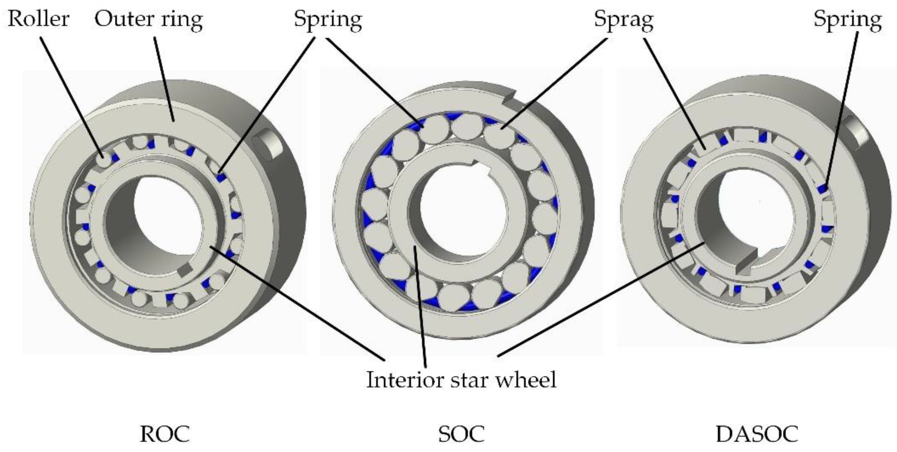
Figure 5 shows a schematic diagram of the 3D model of three overrunning clutches, all of which are composed of an outer ring, an inner ring, rollers, and springs. The differences between them are in the structures of the rollers, inner rings, and springs, which result in great differences in their contact stresses in the bonding condition. The contact stress of the overrunning clutch depends on the structural form and size. To ensure the effectiveness of the comparison, it was conducted under the condition that the outer diameter, inner diameter, and thickness of the three overrunning clutches were the same. The working principle and key parameters of the three overrunning clutches are shown in
Figure 6.
In
Figure 6,
and
are the normal and tangential force of ROC at Point A.
and
are the normal and tangential force of ROC at Point B.
and
are the normal and tangential force of SOC at Point A.
and
are the normal and tangential force of SOC at Point B. The parameter of DASOC and its definition remains the same in
Figure 1 and
Figure 2.
,
and
are the torque of ROC, SOC and DASOC.
4.1. The Contact Stress Comparison between ROC and DASOC
According to the theory of ROC [
10,
11], the force at B and A are given in Equation (17)
When the range of
is 7.5°~8.5°, the resultant force of ROC at Points A and B are given in Equation (18).
The roller stress at Points A and B can be given by the Hertz stress formula in Equation (19)
When the input torques of the two clutches are equal, that is
=
. Comparing Equations (16) and (19), the ratio of the stress at Points A and B of the two overrunning clutches can be obtained, as shown in Equation (20)
and are the ratios of the roller contact stress of the ROC to the double arc sprag contact stress of DASOC at Points A and B, respectively.
Due to , , , , , .
In general, fatigue failure usually occurs at Point B, where the rollers and the inner star wheel contact. It may be assumed that the stress of the two overrunning clutches at Point B is equal, which can also be expressed as
. By comparing Equations (16) and (19), the ratio of the input torques of the two overrunning clutches can be obtained, as shown in Equation (21), where
is the rated torque ratio of DASOC and ROC.
4.2. The Contact Stress Comparison with SOC
According to the theory of SOC [
4], when the range of
is 7.5°~8.5°, the resultant forces of the SOC at Points A and B are given in Equation (22), where
is the number of sprags, and
is the inner radius of the outer ring.
The roller stress at Points A and B can be given by the Hertz stress formula in Equation (25), where
and
are the radii of the upper arc and lower arc, respectively.
When the input torques of the two overrunning clutches are equal, it is represented by
=
. Comparing Formulas (17) and (24), the ratio of the stress at Point A and Point B of the two overrunning clutches can be obtained, as shown in Equation (24).
Assuming that the stresses of the two overrunning clutches at Point B are equal, that is
. The ratio of the input torques of the two overrunning clutches can be obtained by comparing Equations (16) and (23), as shown in Equation (25), where
is the rated torque ratio of DASOC and ROC.
4.3. Contact Stress Calculation of Three Overrunning Clutches
The ROC and DASOC are designed with the same structural parameters, based on an SOC on the market. The outer diameter, the inner diameter, and the thickness of the inner ring of the SOC are 52 mm, 20 mm, and 23 mm, respectively, and the rated torque of the SOC is 95 Nm, etc. Other key structural parameters of the three are shown in
Table 2.
is the diameter of the inner diameter of OCs. is the outer diameter of the SOC or the inner star wheel of the ROC and DASOC cut to the outer circle diameter. is the radius of the ROC, is the upper arc radius of the wedge or double arc sprag, is the lower arc radius of the wedge or double arc sprag, is the width of the roller, wedge, or double arc sprag, Z is the number of rollers, and is the wedge angle of the roller type overtaking clutch or double arc sprag overtaking clutch.
When
, the tangential and normal force of three types of overrunning clutch can be given by Equations (8), (18) and (22), which are
,
, and
, respectively. The Hertz contact stress at Points A and B can be given by Equations (16), (19) and (23), which are shown in
Table 3.
The calculation in
Table 3 shows that DASOC has the minimum stress under the same load. The contact stress of the SOC at Points A and B are 1.9 and 1.45 times that of the DASOC, and the contact stress of the ROC at the same position is 2.78 and 2.44 times that of the DASOC. This means that the DASOC withstands greater loads and can achieve longer life.
When
= 95 Nm and
, the rated torque of the three types of overrunning clutches are shown in
Table 4.
5. Experiment
There are two purposes in the experiment. The first is to verify the effectiveness of the overrunning clutch with a new structure, which means the self-locking performance and overrunning performance. The second is the torsional stiffness test. Especially in the continuously pulsating variable transmission, the torque directly affects its working efficiency. The characteristic of the large torsional stiffness of DASOC is verified through the torsional stiffness contrast test with the typical ROC and SOC.
5.1. Experiment with the Bonding Condition and Overrunning Condition
To compare the experimental results for torsion stiffness, the materials of the outer ring, roller, and inner star wheel were all surface hardened, and had hardnesses of 55–60 HRC. The geometric parameter is shown in
Table 2.
Figure 7 shows the structure of the DASOC and its three major parts in detail.
The experiment began with the non-lubrication condition. In this condition, the inner star wheel was fixed by chassis and loaded with a bar. The DASOC showed reliable self-locking phenomenon without sliding in clockwise rotation. The counterclockwise rotation was smooth and did not become stuck. The oil lubrication experiment was also conducted. The lubricant oil was added between the roller, the outer ring, and the inner star wheel. The phenomenon was the same as for the non-lubrication condition. The self-locking phenomenon also appeared in the clockwise rotation and the unlocking phenomenon was also smooth. This experiment showed the validity of the DASOC.
5.2. A Comparative Experiment in Torsion Stiffness with Three Overrunning Clutches
5.2.1. Structure Description of Three Overrunning Clutches
The structural parameters of the three overrunning clutches are shown in the data in
Table 1 above. The SOC was purchased from the market, and its rated torque was 95 Nm. The other two overrunning clutches were designed and manufactured according to the data in
Table 1. The material of the three overrunning clutches was GCr15, and the heat treatment hardness of the outer ring, roller, and inner star wheel was HRC55-60. The photos of the three overrunning clutches are shown in
Figure 8. Although from
Figure 8 it can be seen that the keys of the three overrunning clutches were not completely consistent, the experimental results show that the shapes of the keys had little influence on the stiffness.
5.2.2. The Experiment Platform and Torsion Stiffness Experiment
A test system, as shown in
Figure 9, was constructed to measure the torsion stiffness experimental device beyond the clutch. The system was composed of a chassis, monitor, overrunning clutch, force arm, micrometer, force sensor, screw, and force-adding nut.
The force sensor was the core part of the experiment system. It was combined with the screw at the bottom and combined with the rod at the top. When the nut was screwed, the force sensor transmitted the force signal to the monitor, where the force could be displayed. The displacement at the end of the rod was measured by a micrometer.
The distance between the loading position of the force arm and the overrunning clutch was
. Before loading, the initial position of the force arm was measured through a dial indicator. After loading on the force arm, the force arm rotated counterclockwise by one degree and then stopped due to system deformation. At this time, displacement of the force arm was measured through a dial indicator again, then the displacement was recorded as
. By extension, after
loading, the loading force was
, and the displacement was
. Since the deformation was very small, the horizontal distance from the loading point to the center of the overrunning clutch was unchanged. The elastic displacement of the loading bar was
, which was calculated by material mechanics. The displacement at the head of the booster rod caused by the deformation of the overrunning clutch can be expressed as Equation (26).
The actual angular displacement of the overrunning clutch is shown in Equation (27).
The definition of torsion stiffness is Equation (28)
The torsion stiffness Equation (29) can be calculated with Equations (27) and (28)
The average torsion stiffness is shown in Equation (30).
5.2.3. The Result and Analysis of the Experiment
Through the experiment method described above, the loading test was carried out on each of the three overrunning clutches, and the obtained data are shown in
Table 5.
The torque load was taken as the abscissa, and the overrunning clutch angle
=
was taken as the ordinate to perform curve fitting, and the obtained fitting curve is shown in
Figure 10. The values of the average torsion stiffness are presented in
Table 6.
It can be seen from
Table 6 that the torsional stiffness of DASOC was the largest, being 4.6 times that of the ROC, and 6.2 times that of the SOC.
6. Conclusions
A new overrunning clutch based on the ROC was proposed in this paper, replacing the roller in the ROC with a double arc sprag. In this paper, the theoretical analysis and experimental study of its key mechanical properties resulted in the following conclusions. The static mechanical model was established first. The expressions of the bonding condition and overrunning condition were given. The geometry parameters of the double arc sprag were derived, and the value range of the self-locking angle was also given. The contact force and the stress expression between the outer ring, the double arc sprag, and the inner star wheel were derived.
Taking as a prototype the common SOC model product with outer diameter, thickness, and inner diameter of 52 mm, 23 mm and 20 mm, respectively, the ROC and DASOC were designed and manufactured with outer diameter, thickness, and inner diameter equal to those of the SOC. The stress calculation and torsional stiffness tests of the three overrunning clutches were carried out. Compared with the contact stress of the ROC and SOC, the sample calculation showed that the contact stress of the double arc sprag overrunning clutch was the lowest, and it had largest transmission capacity. Under the same contact stress, the transmission capacity of the roller was 5.75 times that of the overrunning clutch and 2.1 times that of the sprag type overrunning clutch. An experimental platform was built to verify that the overrunning clutch could bond reliably and be sensitive to overrunning conditions, both in the absence the presence of oil. Compared with the torsional stiffnesses of the traditional ROC and the SOC, the DASOC had the greatest torsional stiffness, which was 4.6 times that of the ROC and 6.2 times that of the SOC.
7. Further Studies
DASOC is a new type of overrunning clutch using double arc sprags with large curvature radii instead of the circular rollers of the ROC. The simulation and experiment showed that contact stress was reduced by about 40%, and the torsional stiffness was increased about twofold. This clutch has important research and application value. In the future, the following topics must be further studied:
(1) Calculation and analysis methods regarding the torsional stiffness of the DASOC. Torsional stiffness is an important basis for the design and dynamics analysis of the overrunning clutch, and the torsional stiffness depends on the normal stiffness of the outer ring, roller, and inner star wheel, and the geometric relationship between them. The geometric relationship and the constitutive relationship of the normal stiffness should be studied, and the calculation and analysis method of torsional stiffness derived. In fact, the stiffness of the overrunning clutch is the coupling stiffness of the stiffness of the outer ring, the stiffness of the inner ring and the engagement stiffness. However, in this research, it was found that the most influential factor was the engagement stiffness. There are many reasons that affect the engagement stiffness, among which the most prominent one is the dimensional deformation of the slider and the inner and outer rings caused by the force during the engagement process. The detailed calculation of the overrunning clutch stiffness will be further investigated in an important follow-up study.
(2) Study of the bonding energy consumption and damping factor of the double arc sprag overrunning clutch. Damping is an important basis for dynamic analysis, work efficiency analysis and an important indicator of performance. A mechanical model of bonding energy consumption should be established, and the damping factor calculation and analysis method also should be derived.
(3) Fatigue life research. The life of the overrunning clutch refers to the fatigue life. The contact stress and the galling due to wear are important factors affecting the fatigue life. Although this paper provides the calculation methods for measuring contact stress and the qualitative analysis of the life of the overrunning clutch, the quantitative analysis of fatigue life needs further research.


