1. Introduction
As a crucial component of the mechanical system, rotating machinery plays an important role in many fields. Rotor unbalancing is one of the most common problems in rotating machinery [
1] and is the main cause of rotor system faults [
2,
3,
4]. A variety of factors, such as manufacturing, assembly errors, rotor wear, and operating conditions [
5,
6,
7,
8], as well as the irresistible centrifugal inertia forces generated by the rotation, will cause variable disturbance forces, which eventually lead to rotor vibration unbalance [
9]. This vibration often increases the load of the bearing, aggravates wear, makes noise, and shortens the service life of the equipment. Eventually, fatigue gaps in rotating shafts may occur, resulting in safety accidents [
10,
11,
12,
13]. The dynamic balancing of the rotating body to effectively solve the above problems has become one of the essential processes in the manufacturing of motors [
14].
According to the state of balance, rotors can be classified into balanced and unbalanced rotors. When the inertia axis of the rotor does not coincide with the rotation axis [
15,
16,
17,
18], the rotor is said to be unbalanced. The dynamic balancing technology is to change the rotor from an unbalanced state to a balanced state by adjusting the rotor’s mass distribution [
19,
20,
21]. Ideal rotor balance is difficult to achieve in actual production. Generally, when the rotor operates stably and the amplitude of the rotor is reduced to the allowable range [
22]—that is, residual unbalance vector—rotor balance is considered to have been achieved in engineering [
23].
Correction is a vital step of rotor dynamic balancing. There are two methods of rotor dynamic balancing: weight removing and weight adding. The weight adding correction is mostly used for manual operation, while the weight-removing correction is mostly for automatic balancing machines, with high weight-removing efficiency. For weight removal correction, problems for the rotor, such as milling position deviations and poor milling accuracy, always exist. Depending on the different milling cutters, the main types of weight removal correction for automatic balancing machines for micromotor armatures are R-shaped milling unbalance correction and V-shaped milling unbalance correction. In addition to accurately measuring the unbalance signal, it is also necessary to obtain the size and position of the rotor unbalance mass through dynamic balancing analysis. Finally, accurate modeling is carried out through the magnitude of the unbalance between the milling material part and the rotor. Liu et al. [
24] developed an unbalance weight removal model based on R-shaped milling cutters for the case of the distribution of slots on the circumference of the motor rotor. Liu et.al. [
25] conducted integral modeling for V-shaped milling unbalance correction. To apply integral modeling to the programmable logic controller (PLC), they simplified some milling depth formulas using numerical analysis methods. Zeng et al. [
26] carried out tooth face modeling for V-shaped milling. To decompose the initial unbalance vector of the rotor based on the maximum weight-removing milling vector, they derived an efficient multi-milling tooth correction milling method applicable to PLC. Fan et al. [
27] established a mathematical model of the rotor online active balancing influence coefficient table method for the single-plane rotor online active balancing problem and simplified the influence coefficient table method to improve the online balancing efficiency. For the wear caused by repeated machining operations of milling cutters, Tseng et al. [
28] developed a compensation algorithm to estimate the parameter settings required in the milling vector calculation matrix. Zhang [
29] et al. proposed an iterative control method with a variable weight-removing rate to improve the unbalance correction accuracy for the structural characteristics of a thin disc component with a high diameter–thickness ratio, leading to a small unbalance mass that can also form a large unbalance vector. The micromotor armature requires extremely high correction accuracy, but the milling depth deviation, angle deviation, and model deviation will have a certain impact on the correction accuracy, so the accuracy of the milling model obtained by simplifying the integration formula cannot easily meet the accuracy requirements. Therefore, this paper proposes a discrete vector model to discretize and integrate the unit unbalance vector. The higher the discretization accuracy, the higher the integration accuracy.
A discrete vector model is established to solve the problem of position deviation and insufficient milling accuracy, then a set of discrete points according to the edge curve of the milling cutter and rotor to replace the milling space of the milling cutter to the rotor can be generated. Finally, the numerical relationship between milling depth and unbalance vector can be obtained. Combined with the modified influence coefficient method, this model can be applied to the micromotor armature milling correction to effectively improve the rotor correction accuracy.
2. Milling Correction for Rigid Rotor Balancing
A rigid rotor can be regarded as composed of countless particles, each of which generates centrifugal forces. The distance between each mass and the center of the rotor on its surface is different, which leads to different magnitudes. As shown in
Figure 1, the principle of dynamic balancing of a rigid rotor is to make the unbalanced forces generated at various places when the rotor rotates at high speed equivalent at one or more positions, where A and B are equivalent surfaces. The equivalent force position is a point with no size, and the milling cutter mills a region around that point.
where
is the unbalanced force generated by each face and
and
are the resultant forces distributed to measuring surface
A and
B, respectively, through
The influence coefficient method is currently the most commonly used method for the dynamic balancing of rigid rotors. This method is suitable for the correction of dynamic unbalance conditions in rigid rotors and is widely used in engineering due to its simplicity. By measuring the linear relationship between the unbalance vector and the amplitude of the selected plane of the rotor, the influence coefficient and the correction mass of the plane are obtained so that the rotor balance can be achieved.
After the unbalance vector of the rotor has been measured and calculated by the influence coefficient method, a V-shaped milling-weight-removing correction is performed. According to the relationship between the size of the rotor unbalance vector and the milling depth of the V-shaped milling cutter, the milling cutter mills the calculated depth at the specified position, thus correcting the unbalance vector of the rotor for the balance. As shown in
Figure 2, the milling cutter moves vertically to realize the radial milling of the rotor, thus removing the material at the location of the rotor’s unbalance mass. It is only necessary to know the radius of the milling cutter, the half-edge angle of the milling cutter, the length of the flat edge section of the milling cutter, and the material and radius of the rotor to calculate the depth that the milling cutter should mill for the rotor with a different unbalance vector.
For micromotor armatures, the integral formula for the milling model is too complex, and the simplified model leads to a lack of accuracy. In order to solve the above problems, this paper improves the dynamic balancing accuracy by establishing a discrete vector milling model and correcting the influence coefficients according to the actual milling conditions.
3. Analytical Model of V-Shaped Milling Weight Removal
Through a discrete vector modeling approach, all centrifugal forces generated in each unit area are concentrated and equivalent to the center line of the weight removal model. Since there exists a linear relationship between the centrifugal force generated in the milling area and the unbalance vector, by combining the equivalent mass approach with the results of the influence coefficient method, the milling position and depth are obtained to correct the balance of the rotor. The equivalent mass approach is that the milling part mass produces the same balancing effect at a point as the equivalent mass at this point.
As established in the V-shaped weight-removing vector model,
Figure 3 shows the schematic diagram of the rotor and the V-shaped milling cutter during milling. The rotor is tangential to the milling cutter in the initial position, and the depth of mill is
t = 0; with the increase of the depth of mill, the intersection area in
Figure 3 gradually increases, where
Figure 3a is the cross-sectional view of the milling cutter milling the rotor on the X–Z plane and
Figure 3b is the sectional view of the milling cutter milling the rotor on the X–Y plane.
When
z = 0,
Figure 3b is a cross-section on the X–Y plane of the milling center, in which the left envelope in the shaded area shows the inner edge curve of the milling cutter after milling the rotor:
The right envelope of the shaded area is the edge curve of the outermost milling area of the rotor:
where
R is the rotor radius;
r is the radius of the milling cutter;
α is the half-edge angle of the milling cutter;
d is the length of the flat edge section of the milling cutter;
t is the depth of mill; and
D is the width of the milling cutter.
y1 is the maximum value of the shaded area along the Y direction when
z = 0 shown in
Figure 3b. The expression for
y1 concerning the depth of mill
t is obtained by combining Equation (2) with Equation (3) as:
The shaded area of the cross-section on the X–Z plane in
Figure 3a is related to the value of the Y-axis coordinate point. The left envelope of the shaded area is the inner edge curve of the milling cutter milling area:
The left envelope of the shaded area is the peripheral curve of the rotor:
where
z1 is the maximum value of the shaded area along the Z direction. The expression for
z1 concerning
y is obtained by combining Equation (5) with Equation (6):
When the depth of mill
t is determined, the X–Z cross-sectional area is divided along the Y-axis to obtain the expression for the volume of the milling area
V as follows:
The rotor unbalance is generally expressed as
U, the value of which is equal to the product of the mass of a point on the correction plane of the rotor and the distance from that point to the rotor axis, corresponding to the expression for the unbalance of the milling area
U as follows:
where
ρ is the density of the rotor milling area.
4. Modification of V-Shaped Milling Correction Theory
4.1. Discrete Model of V-Shaped Milling Weight Removal
Due to the above Formulae (8) and (9), it can be seen that the integral formula is very complex, and it is difficult to obtain an accurate integral analytical formula. Therefore, a set of discrete points is generated according to the edge curve of the milling cutter and rotor to replace the milling space of the milling cutter on the rotor, on which the coordinates of each discrete point are (
xijk,
yi,
zij). The density of the rotor milling area is
ρ, the discrete spacing is
K, a single point occupies the space as
K3, and the resulting unbalance effect is:
As shown in
Figure 4, the milling area is centrosymmetric, and the two red squares in
Figure 4a are all at the same value from the X-axis and Y-axis. In different X–Y sections, the centrifugal forces in the perpendicular direction to the axis of rotation counterbalance each other, leaving only the centrifugal force in the X-axis direction. The forces of the two discrete blocks are combined in the X-axis direction, and the magnitude is:
The two discrete blocks in
Figure 4b are symmetrical with the X-axis and Z-axis. The centrifugal force of the discrete blocks in
Figure 4a is synthesized in the X-axis direction of the circular section in the above manner, and then the centrifugal force on the opposite symmetrical Z-axis is synthesized on the X-axis. At this time, the synthetic axis is the center line of the milling area, and the magnitude of the synthetic force is:
Similarly, superimposition of all discrete spaces is performed, with the resulting unbalance effect being obtaining the volume
V of this milling area with the unbalance vector
U.
where
a,
b, and
c are the number of discrete nodes corresponding to the Y-axis direction, Z-axis direction, and X-axis direction, respectively:
y1 and -
y1 are the two edge points of the rotor milling area in the Y-axis direction, and
yi is the discrete point generated by
y1 and -
y1 along the inner side of the milling area in the negative direction of the Y-axis:
z1 and -
z1 are the two edge points of the rotor milling area in the Z-axis direction, and
zij is the discrete point generated by
z1 and -
z1 along the inner side of the milling area in the negative Z-axis direction:
x1 and
x2 are the two edge points of the rotor milling area in the X-axis direction, and
xijk is the discrete point generated by
x1 and
x2 along the inner side of the milling area in the positive X-axis direction:
To verify the accuracy of the discrete model, we use the 3D software-generated milling volume as a standard, which is compared to the volume generated by the simplified integration and the volume of the discrete model. The parameters of the micromotor armature and milling cutter used for the simulation experiments are shown in
Table 1. As shown in
Table 2, E1 is the error between the volume generated by the 3D software and the volume calculated with the discrete model, and E2 is the error between the volume generated by the 3D software and the volume calculated with the simplified integration. From the numerical point of view, the error between the discrete model and the 3D model is extremely small, and the error between the integral model and the 3D model increases as the depth of mill increases. The main reason for this is that the simplified integral model simplifies the outermost arc as a straight-line tangent to it, which then forms a triangular area with the two diagonal lines of the milling model. As the depth of mill becomes greater, the gap to be filled becomes greater. Moreover, since the unbalance force induced by the unbalance mass is proportional to the distance from the center point of the mass to the axis of rotation. In the integral model, the position to be filled is furthest from the center of the rotor, which has a greater error in unbalance vector than its volume error.
4.2. Weighting and Milling Plane Conversion
By measuring the linear relationship between the unbalance vector and amplitude of the selected plane of the rotor, the influence coefficient and correction mass of the plane are obtained. Thus, the method of achieving the rotor dynamic balancing is called the influence coefficient method. As shown in
Figure 5, during the trial weighting of the rotor, the weighting center does not coincide with the center of the milling area, and the trial weighting is a necessary step to obtain the rotor balancing mass using the influence coefficient method. The balancing amount and the trial weighting center are on the same plane.
The balancing mass obtained by the influence coefficient is the added weight, while the milling cutter milling is the removed weight, with a difference of 180° between the two. The dynamic balancing principle of the rotor is used to transform the unbalance vector in the trial weight center of the rotor towards the plane where the center of the milling area is located to obtain the new unbalance vector.
As shown in
Figure 6a, the specific removed unbalance vectors
and
are obtained using the modified influence coefficient method The unbalanced forces generated by the removed weight part of the rotor during its high-speed rotation are
and
, which are located on the same cross-sectional circle as the center of the rotor trial weight.
Fa and
Fb are the combined forces generated during the rotation of the rotor milling area, located on the same cross-sectional circle as the center of the rotor milling area, and they are not on the same cross-sectional circle. As shown in
Figure 6b,
and
are transformed to the center face of the milling area, and finally, the resultant unbalance vector of the milling area is obtained:
When the unbalance vector is large, the required milling depth is larger. If the center of the mill is close to the shaft end, this results in a half-length z1 of the milling area exceeding the distance between the center of the mill and the shaft end. To avoid empty milling, the position of the milling center must be readjusted.
4.3. Milling Times of Micromotor Armatures
4.3.1. Small Unbalance
For the five-slot micromotor armature, as shown in
Figure 7, the milling depth is inconsistent in different areas, with the maximum milling depth being when the center of milling is at the center of the tooth face.
is decomposed at the center of the nearest two adjacent tooth faces.
There is a positive proportional relationship between the force and the balancing vector, and the decomposition of the force can be directly replaced by the decomposition of the balancing vector, that is:
For the five-slot micromotor armature, the angle between every two slots is 2π/5. Assume that the angle between
and
is
θ and that the angle between
and
is 2π/5-θ. The magnitudes of
and
are:
After obtaining the magnitudes of and , the actual milling is performed according to the corresponding relationship between the milling depth t and the unbalance vector .
4.3.2. Unbalance Exceeds a Certain Value
When the unbalance exceeds a certain value, if the milling cutter only mills at the position of the maximum tooth face thickness of the rotor because the two tooth face centers furthest away from the milling area are more than 90° to the direction of the milling force, only three tooth face centers can be weight removal balanced. The tooth face center closest to the milling force is milled with the maximum milling depth tm, and the remaining residual force is decomposed to the other two tooth face centers.
For rotors with fewer slots, there are limitations in decomposing the milling forces only to the center of the tooth face. When the milling center is rightly the center of the tooth face, the milling depth range becomes larger. However, due to the low number of slots, the angle difference between the centers of the tooth surface is larger, resulting in the large milling force decomposed at the center of the tooth face. When the unbalance vector exceeds a certain value, the decomposition of two and three sides can no longer meet the balance requirements, so it is necessary to consider milling at the non-surface center.
When
is larger than the maximum malleable unbalance vector
, according to the angle occupied by the maximum malleable volume as
β. As shown in
Figure 8 and
Figure 9, when milling multiple positions on the same tooth face, the angle between the center line of the tooth face and the center line of the position is
γ. The magnitude of this unbalance vector
is:
For rotors with a large number of slots, the angle between the centers of the tooth faces is small. The periphery of the micromotor armature is composed of tooth surfaces and slots. The area of unbalance vector that can be milled by the milling cutter is the part where the slot is removed. If the milling center is not set at the thickest position of the tooth face, the milling area may be partially at the slot, resulting in empty milling, which will affect the actual dynamic balance accuracy of the rotor. The principle of milling unbalance vector distribution for multi-slot rotors is the same as for five-slot micromotor armatures.
5. Experiment Verification
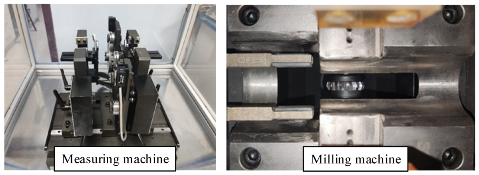
The above analysis has completed the conversion between the discrete modeling of the milling area of the V-shaped milling cutter and the influence coefficient method of balancing vector and splitting times. The balanced accuracy of the method is verified by the weight removal pass rate of specific experiments. As shown in
Figure 10, the experimental machines are dynamic balancing machine for measuring unbalance vector and milling unbalance mass machine. The rotor dynamic balancing machine uses the Keen KV-8000 PLC as the controller for the actual milling study. The selected milling cutter parameters are milling cutter radius
r = 13 mm, milling cutter half edge angle
α = 50°, and milling cutter flat edge section length
d = 0.4 mm. The selected rotors are five-slot micromotor armatures, as shown in
Figure 11. The rotor parameters are rotor radius
R = 11.5 mm, rotor density
ρ = 7.85 g/cm
3, and rotor length
L = 22.5 mm. Rotor milling is carried out according to the correspondence between the milling depth of the milling cutter and the magnitude of the unbalance vector mill. The ratio between the difference of the rotor unbalance before and after milling and the initial unbalance before milling is used as the basis for judging the balancing effect, i.e., the residual unbalance vector rate. The residual unbalance vector rate is one of the most important indexes for the comprehensive performance evaluation of a dynamic balancing machine and it is customary to convert this ratio into a percentage.
where
Aij is the initial unbalanced mass of the rotor,
Bij is the unbalanced mass of the rotor after milling, and
Pij is the residual unbalance vector rate of the rotor.
As shown in
Figure 12, the above method and the rotor are applied to the dynamic balancing machine for testing. The micromotor armature balancing accuracy adopts G2.5 class, the armature speed is 2100 r/min, and the power rating of the electric machine is 288 W when the unbalance masses of both the left and right side of the rotor are below 20 mg, and all rotors qualified.
The result of the influence coefficient method is a mass that can be compared and balanced in two ways: one is by finding the corresponding unbalance vector by multiplying the mass found by the influence coefficient by the rotor radius, as shown in
Figure 13a, to obtain the milling depth; the other is by obtaining the equivalent mass by dividing the unbalance vector by the rotor radius, as shown in
Figure 13b, where the blue curve is the mass of the milling area and the red curve is the equivalent mass of the milling area.
As the milling machine has an accuracy of 0.01 mm, it can be seen in
Figure 13b that as the milling depth becomes greater, the difference in mass between each 0.01 mm becomes greater. The larger the rotor unbalance vector, the larger the resulting error. There is also a slight difference in rotor material density from one manufacturer to another, which also affects the dynamic balancing accuracy.
The rotor has a maximum milling depth of 1 mm, an angle of 17.11°, and a milling mass of 86.42 mg. The milling center is set at a distance of 5 mm from the outermost circle of the rotor so that when the rotor has a milling depth of 1 mm, the half-length of the milling area in the direction parallel to the rotor axis is 5 mm and no empty milling occurs. The angle occupied by each tooth of the five-slot rotor is π/3. The farther away from the center of the tooth, the more fragile the part is, so the milling center of the splitting part must be as close to the center of the tooth as possible while also avoiding touching the tool. The unbalanced mass on the left side of rotor 2 is 93.75 mg at 252°. The unbalanced mass is greater than 83.83 mg, and the remaining 9.92 mg must be distributed at 234° and 270°. The rest of the rotor does not need to be split. As can be seen from the experimental results in
Table 3, the residual unbalance vector of the rotor after milling is 87.4% with the use of the correction model. The residual unbalance mass on both the left and right sides of the rotor is below 20 mg, and all rotors qualified. This solution can achieve high accuracy weight-removing correction.
6. Conclusions
Focusing on the V-shaped milling weight-removing modeling, this paper analyzed the impact of the rotor milling area center and the trial weight center not being in the same plane on the rotor milling mass and milling position and improved the one-time weight-removing rate and weight-removing qualification rate of the rotor unbalance. With the objective of rotor dynamic balancing accuracy, the residual unbalance mass on both the left and right sides of the rotor is below 20 mg, and all rotors qualified.
The simplified integral model generates errors in cases when the depth of mill is high or the radius of the milling cutter is significantly larger than the radius of the rotor. In comparison with the simplified integral model, the discrete model is effectively able to avoid errors arising from filling the gap between the triangle and the arc. For small rotors, the discrete accuracy can reach 0.01 mm. For large rotors, the discrete accuracy should be selected so that the relative accuracy is the same as for small rotors, depending on the size of the rotor. If the discrete precision chosen is too small, the program will run too slowly or even fail to operate properly.
However, in actual motor operation, the milling of the eccentric effect can also cause changes in motor performance due to changes in the core state. In order to improve rotor performance, we will consider more rotor application scenarios in our future research to improve the eccentricity effect while avoiding negative effects on the application scenarios due to changes in stress, temperature, and magnetic flux.
Author Contributions
Conceptualization, M.L.; methodology, M.L.; software, Y.S.; validation, R.D., formal analysis, W.C.; investigation, Y.S.; resources, W.C. and D.J.; data curation, M.L. and D.J.; writing—original draft preparation, M.L.; writing—review and editing, D.J.; visualization, W.C.; supervision, D.J.; project administration, W.C.; funding acquisition, D.J. All authors have read and agreed to the published version of the manuscript.
Funding
This research was funded by the Young Science and Technology Innovation Fund of Nanjing Forestry University, grant number CX2019010; the National Natural Science Foundation of China, grant number 11602112; Supported by the Qinglan project; Foundation of Higher Education Institutions in Jiangsu Province, grant number 20KJB460003; and the National Natural Science Foundation of China, grant number BK20200787.
Institutional Review Board Statement
Not applicable.
Informed Consent Statement
Not applicable.
Data Availability Statement
Not applicable.
Conflicts of Interest
The authors declare no conflict of interest.
References
- Silva, A.; Cavalini, A.; Steffen, V. Model based robust balancing approach for rotating machines. In Proceedings of the Society for Experimental Mechanics Series, Orlando, FL, USA; Springer: Cham, Switzerland, 2016; Volume 3, pp. 243–251. [Google Scholar] [CrossRef]
- Ye, R.; Wang, L.; Hou, X.; Luo, Z.; Han, Q. Balancing method without trial weights for rotor systems based on similitude scale model. Front. Mech. Eng. 2018, 13, 571–580. [Google Scholar] [CrossRef]
- Ye, M.; Yan, X.; Jia, M. Rolling Bearing Fault Diagnosis Based on VMD-MPE and PSO-SVM. Entropy 2021, 23, 762. [Google Scholar] [CrossRef] [PubMed]
- Xu, Y.; Liu, J.; Wan, Z.; Zhang, D.; Jiang, D. Rotor fault diagnosis using domain-adversarial neural network with time-frequency analysis. Machines 2022, 10, 610. [Google Scholar] [CrossRef]
- Kelm, R.; Kelm, W.; Pavelek, D. Rotor balancing tutorial. In Proceedings of the 45th Turbomachinery Symposium, Houston, TX, USA, 12–15 September 2016. [Google Scholar] [CrossRef]
- Al Abbood, M.T.S. A new mathematical analysis of two-plane balancing for long rotors without phase data. Assoc. Arab Univ. J. Eng. Sci. 2019, 26, 44–48. [Google Scholar] [CrossRef]
- Bhende, A. Dynamic balancing of two-plane rotor without phase angle measurement using amplitude subtraction method. Noise Vib. Worldw. 2019, 50, 328–333. [Google Scholar] [CrossRef]
- Xu, Y.; Tian, Y.; Li, Q.; Li, Y.; Zhang, D.; Jiang, D. Vibro-impact response analysis of collision with clearance: A Tutorial. Machines 2022, 10, 814. [Google Scholar] [CrossRef]
- Ibraheem, A.; Ghazaly, N.; Abd El-Jaber, G. Review of rotor balancing techniques. Am. J. Ind. Eng. 2019, 6, 19–25. [Google Scholar] [CrossRef]
- Yun, Z.; Qiao, W.; Zou, D.; Shao, M. Study on the relationship between the imbalance status and its vibration response in balancing method of rotors. In Proceedings of the 23rd International Congress on Sound and Vibration, Athens, Greece, 10–14 July 2016; pp. 10–14. [Google Scholar]
- Chung, Y.; Chen, Y. Adaptive vision-based method for rotor dynamic balance system. IEEE Access 2021, 9, 22996–23006. [Google Scholar] [CrossRef]
- Zhou, J.; Xu, L.; Xuan, Y.; Xu, Y.; Liu, G. Shedding frequency and motion of jujube fruits in various excitation modes. Trans. ASABE 2020, 63, 881–889. [Google Scholar] [CrossRef]
- Vuojolainen, J.; Jastrzebski, R.; Pyrhonen, O. Balancing of a rotor with active magnetic bearing system: Comparison of one-and two-plane balancing Procedures. In Proceedings of the EPE ECCE Europe, Riga, Latvia, 17–21 September 2018; Volume 9, pp. 17–21. [Google Scholar]
- Yan, Z.; Ji, W.; Ding, K. Effect of dynamic balance parameters on vibration of vertical and horizontal rotor system. In Proceedings of the 5th International Conference on Mechanical Engineering and Automation Science, Wuhan, China, 10–12 October 2019; Volume 10, pp. 10–12. [Google Scholar]
- Deng, Z.; Shen, H.; Wang, K.; Jin, H. Vibration improvement and dynamic balance automatic optimization of rotor compressor. In Proceedings of the 2nd World Conference on Mechanical Engineering and Intelligent Manufacturing, Shanghai, China, 22–24 November 2019; pp. 224–228. [Google Scholar] [CrossRef]
- Kimmelmann, M.; Stehle, T. Measuring unbalance-induced vibrations in rotating tools. In Proceedings of the 8th International Conference on Manufacturing Science and Education, Sibiu, Romania, 7–9 July 2017; Volume 6, pp. 7–9. [Google Scholar]
- Xu, Z.; Guo, Y.; Zhu, J. Design and parameters optimization on intelligent control devices. Intell. Vib. Control Civil Eng. Struct. 2017, 5, 151–171. [Google Scholar] [CrossRef]
- Masuch, M.; Lindenfels, J.; Seefried, J.; Mayr, A.; Schneider, M.; Weigelt, M.; Kühl, A.; Franke, J.; Hemmer, C. Comparison of additive balancing processes for rotors in the context of high speed electric traction motors. In Proceedings of the 2019 9th International Electric Drives Production Conference, Esslingen, Germany, 3–4 December 2019. [Google Scholar]
- Hou, X.; Wang, E.; Cao, H.; Zhu, Y.; Qi, K. Research on dynamic balance adjustment method of single braced frame gyroscope rotor. In Proceedings of the 5th International Conference on Mechatronics and Mechanical Engineering, Nagoya, Japan, 20–23 April 2018; Volume 11, pp. 10–12. [Google Scholar]
- Zhou, J.; Xu, L.; Zhang, A.; Hang, X. Finite element explicit dynamics simulation of motion and shedding of jujube fruits under forced vibration. Comput. Electron. Agric. 2022, 198, 107009. [Google Scholar] [CrossRef]
- Yu, W.; Liu, Z.; Zhuang, Z.; Liu, Y.; Wang, X.; Yang, Y.; Gou, B. Super-resolution reconstruction of speckle images of engineered bamboo based on an attention-dense residual network. Sensors 2022, 22, 6693. [Google Scholar] [CrossRef] [PubMed]
- Li, L.; Cao, S.; Li, J.; Nie, R.; Hou, L. Review of rotor balancing methods. Machines 2021, 9, 89. [Google Scholar] [CrossRef]
- Zhang, Y.; Li, M.; Hu, Y. Model-based balancing method of rotors using differential evolution algorithm. In Proceedings of the International Conference on Measuring Technology and Mechatronics Automation, Phuket, Thailand, 28–29 February 2020; Volume 751, p. 012046. [Google Scholar] [CrossRef]
- Liu, J.; Pan, S.; Yang, K.; Feng, P. Research on key technologies of automatic dynamic balancing machine. J. Zhejiang Univ. Eng. Ed. 2006, 40, 6. [Google Scholar] [CrossRef]
- Liu, Z.; Shen, H.; Zeng, S. Circumferential distribution model of unbalance for motor rotor weight removal. Modul. Mach. Tools Autom. Process. Technol. 2009, 1, 5. [Google Scholar] [CrossRef]
- Zeng, S.; Liu, Z.; Ren, Y. Research on Modeling of weight removal in V-milling of fully automatic balancing machine for motor rotor. J. Mech. Eng. 2010, 46, 187–192. [Google Scholar] [CrossRef]
- Fan, H.; Shi, B.; Jing, M. Modeling and Simulation of rotor single plane on-line active balancing influence coefficient table method. Mech. Sci. Technol. 2018, 37, 5. [Google Scholar] [CrossRef]
- Tseng, C.; Shih, T.; Lin, J. Dynamic balancing scheme for motor armatures. J. Sound Vib. 2007, 304, 110–123. [Google Scholar] [CrossRef]
- Zhang, S.; Zhu, Y.; Zhang, Z. Research on the weight removing model and control method for the unbalance vector of thin disc workpiece. Shock Vib. 2022, 2022, 7638416. [Google Scholar] [CrossRef]
| Publisher’s Note: MDPI stays neutral with regard to jurisdictional claims in published maps and institutional affiliations. |
© 2022 by the authors. Licensee MDPI, Basel, Switzerland. This article is an open access article distributed under the terms and conditions of the Creative Commons Attribution (CC BY) license (https://creativecommons.org/licenses/by/4.0/).


