
Fiber Optic Fiber Bragg Grating Sensing for Monitoring and Testing of Electric Machinery: Current State of the Art and Outlook
 ,
,
Abstract
:1. Introduction
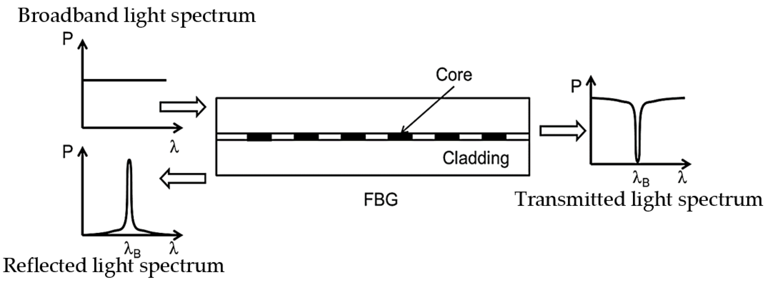
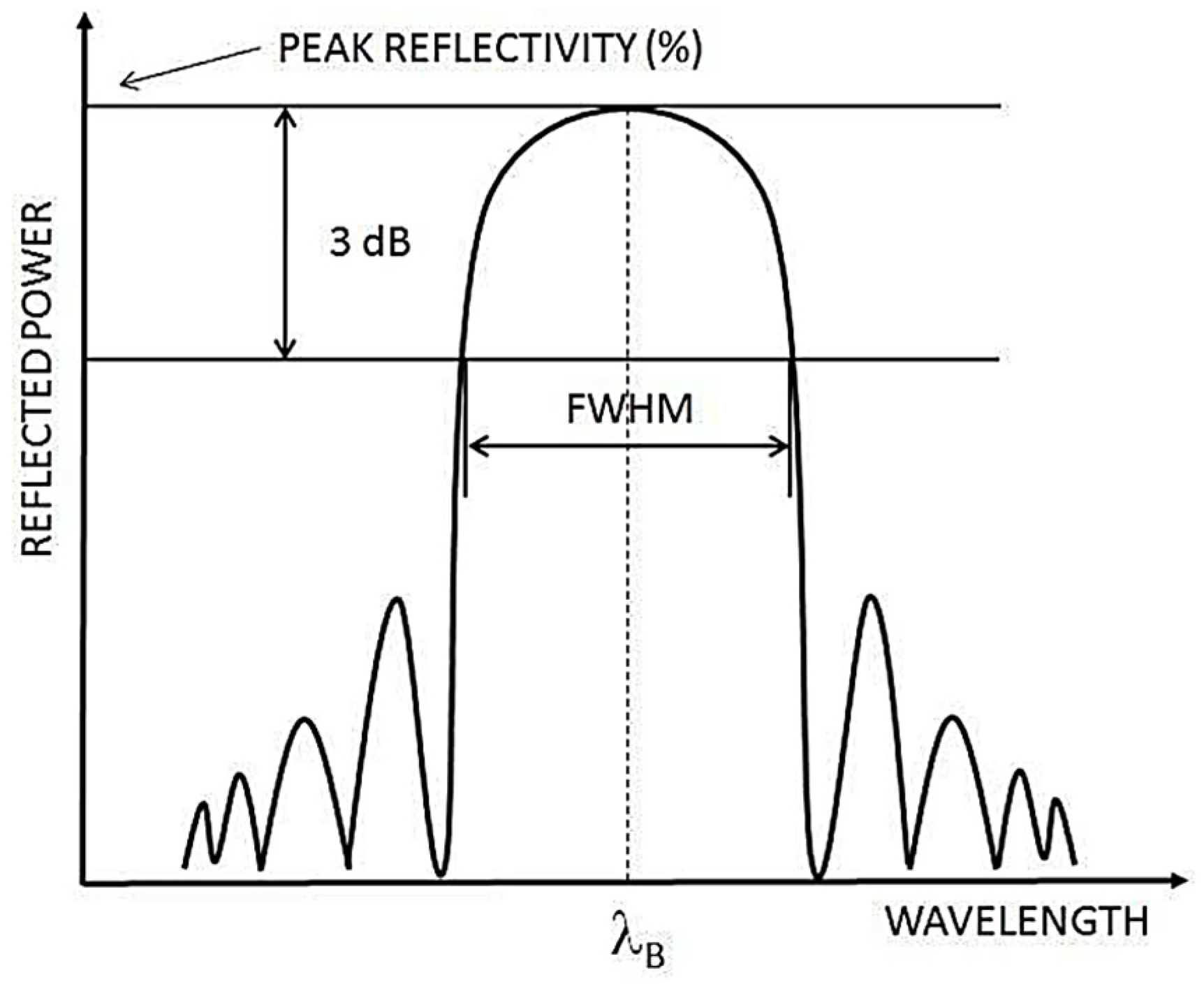
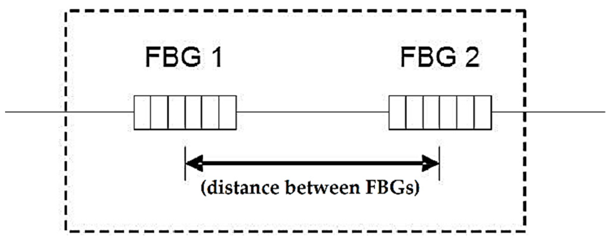
2. Operating Principles of FBG Sensors
3. FBG Sensing Application in Electric Machines
- Immunity to EMI,
- Lower signal-to-noise ratio,
- Electrical passivity, including at the measuring point,
- Flexibility, compactness, and small size,
- The potential for long in-service life,
- Resistance to harsh environments (e.g., extreme temperatures, moisture, corrosion, etc.)
- A multiplexing ability enabling distributed sensing schemes, and,
- A multi-physical sensing capability.
3.1. Thermal Sensing
3.2. Mechanical Sensing
3.2.1. Strain Sensing
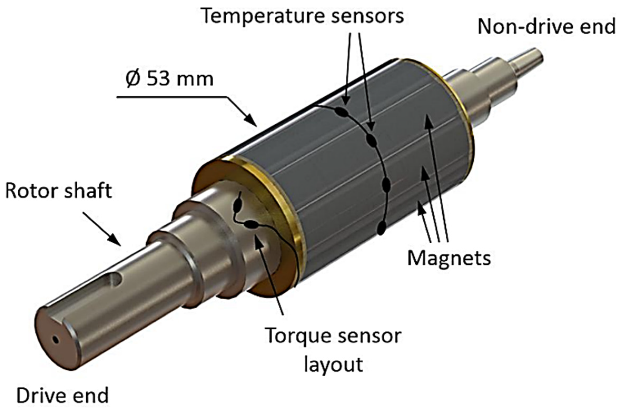
3.2.2. Torque Sensing
3.2.3. Vibration Sensing
3.2.4. Rotational Speed Sensing
3.3. Magnetic Field Sensing Application
3.4. High Voltage Application
3.5. Multiphysical Sensing Application
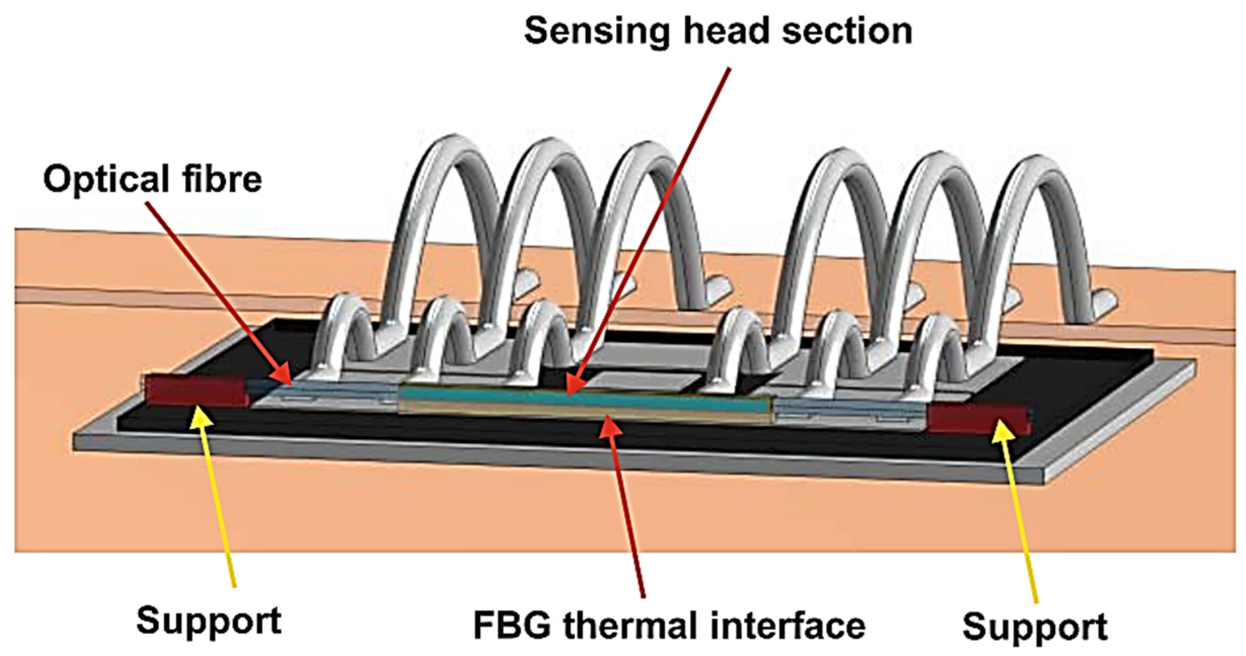
3.6. Power Electronics Device Sensing Application
4. Outlook and Conclusions
Author Contributions
Funding
Institutional Review Board Statement
Informed Consent Statement
Data Availability Statement
Acknowledgments
Conflicts of Interest
Abbreviations
| Symbol/Abbreviation | Description |
| FBG | Fiber Bragg Grating |
| EMI | Electromagnetic interference |
| CM | Condition monitoring |
| UV | Ultraviolet |
| FWHM | Full width at half maximum |
| λB | Bragg wavelength |
| neff | Effective refractive index of the optical fiber |
| Λ | The Bragg grating period |
| ΔλB | The relative change in reflected Bragg wavelength |
| ε | Strain |
| T | Temperature |
| kε | The total strain sensitivity factor |
| kT | The total temperature sensitivity factor |
| TC | Thermocouple |
| RTD | Resistance thermal detector |
| α | the fiber thermal expansion coefficient |
| ξ | The fiber thermo-optic coefficient |
| PEEK | Polyether ether ketone |
| FORJ | Fiber optic rotating joint |
| ILFE | In-line fiber etalon |
| PMSM | Permanent magnet synchronous machine |
| IM | Induction motor |
| HV | High voltage |
| PD | Partial discharge |
| IGBT | Insulated gate bipolar transistor |
References
- Tavner, P.; Ran, R.; Penman, J.; Sedding, H. Condition Monitoring of Rotating Electrical Machines; The Institution of Engineering and Technology: London, UK, 2008; p. 306. [Google Scholar] [CrossRef]
- Toliyat, H.A.; Nandi, S.; Choi, S.; Meshgin-kelk, H. Electric Machines: Modeling, Condition Monitoring, and Fault Diagnosis; CRC Press: Boca Raton, FL, USA, 2013. [Google Scholar] [CrossRef]
- Hind, D.; Gerada, C.; Galea, M.; Bartolo, J.B.; Fabian, M.; Sun, T.; Grattan, K.T.V. Use of Optical Fibres for Multi-parameter Monitoring in Electrical AC Machines. In Proceedings of the 2017 IEEE 11th International Symposium on Diagnostics for Electrical Machines, Power Electronics and Drives (SDEMPED), Tinos, Greece, 29 August–1 September 2017. [Google Scholar] [CrossRef]
- Fabian, M.; Hind, D.M.; Gerada, C.; Sun, T.; Grattan, K.T.V. Comprehensive Monitoring of Electrical Machine Parameters Using an Integrated Fiber Bragg Grating-Based Sensor System. J. Light. Technol. 2018, 36, 1046–1051. [Google Scholar] [CrossRef]
- Fabian, M.; Hind, D.; Gerada, C.; Sun, T.; Grattan, K.T.V. Multi-Parameter Monitoring of Electrical Machines Using Integrated Fibre Bragg Gratings. In Proceedings of the 2017 25th Optical Fiber Sensors Conference (OFS), Jeju, Republic of Korea, 24–28 April 2017. [Google Scholar] [CrossRef]
- Mellor, P.; Roberts, D.; Turner, D. Lumped Parameter Thermal Model for Electrical Machines of TEFC design. In Proceedings of the IEEE Proceedings B—Electric Power Applications, September 1991. [Google Scholar] [CrossRef]
- Sousa, K.D.M.; Hafner, A.A.; Crespim, M.; Somenzi, J.; De Oliveira, V.; Kalinowski, H.J.; Da Silva, J.C.C. Fiber Bragg Grating Sensing Applications in Temperature Monitoring of Three-Phase Induction Motors. In Proceedings of the 2011 SBMO/IEEE MTT-S International Microwave and Optoelectronics Conference (IMOC 2011), Natal, Brazil, 29 October–1 November 2011. [Google Scholar] [CrossRef]
- Tavner, P.J. Review of Condition Monitoring of Rotating Electrical Machines. IET Electr. Power Appl. 2008, 2, 215–247. [Google Scholar] [CrossRef]
- Sarma, N.; Tuohy, P.; Djurović, S. Condition Monitoring of Rotating Electrical Machines. In Reference Module in Materials Science and Materials Engineering; Elsevier: Amsterdam, The Netherlands, 2022. [Google Scholar] [CrossRef]
- Sousa, K.M.; Bazzo, J.P.; Mezzadri, F.; Bortolotti, F.; Martelli, C.; Silva, J.C.C.; Probst, W.K. Optical Fiber Bragg Grating Sensors Applied on Energy Conversion Systems. In Proceedings of the 2013 SBMO/IEEE MTT-S International Microwave & Optoelectronics Conference (IMOC), Rio de Janeiro, Brazil, 4–7 August 2013. [Google Scholar] [CrossRef]
- Mohammed, A.; Djurovic, S. FBG Thermal Sensing Features for Hot Spot Monitoring in Random Wound Electric Machine Coils. IEEE Sens. J. 2017, 17, 3058–3067. [Google Scholar] [CrossRef]
- Melecio, J.I.; Mohammed, A.; Djurović, S. Characterisation of FBG based Magnetic Field Sensor Response Sensitivity to Excitation Orientation for Rotating Electric Machine Applications. In Proceedings of the 2019 8th Mediterranean Conference on Embedded Computing (Meco), Budva, Montenegro, 10–14 June 2019. [Google Scholar] [CrossRef]
- Suryandi, A.A.; Damian, I.E.; Djurović, S. FBG Magnetostrictive Composite Flux Sensor Response Characterisation for Surface Permanent Magnet Rotor Flux Monitoring. In Proceedings of the 2021 10th Mediterranean Conference on Embedded Computing (MECO), Budva, Montenegro, 7–10 June 2021; pp. 1–6. [Google Scholar] [CrossRef]
- Suryandi, A.A.; Djurovic, S. FBG Magnetostrictive Composite Flux Sensor for Monitoring Rotor Permanent Magnet Flux. In Proceedings of the 2022 11th Mediterranean Conference on Embedded Computing (MECO), 7–10 June 2022; pp. 1–6. [Google Scholar] [CrossRef]
- Mohammed, A.; Melecio, J.I.; Djurovic, S. Electrical Machine Permanent Magnets Health Monitoring and Diagnosis Using an Air-gap Magnetic Sensor. IEEE Sens. J. 2020, 20, 5251–5259. [Google Scholar] [CrossRef]
- Fibres, S. FBG Sensing System. Available online: https://www.smartfibres.com/technology (accessed on 14 October 2022).
- Rao, Y.-J. In-fibre Bragg grating sensors. Meas. Sci. Technol. 1997, 8, 355–375. [Google Scholar] [CrossRef]
- Mohammed, A.; Djurović, S. A study of distributed embedded thermal monitoring in electric coils based on FBG sensor multiplexing. Microprocess. Microsyst. 2018, 62, 102–109. [Google Scholar] [CrossRef]
- Mohammed, A.; Hu, B.; Hu, Z.; Djurović, S.; Ran, L.; Barnes, M.; Mawby, P.A. Distributed Thermal Monitoring of Wind Turbine Power Electronic Modules Using FBG Sensing Technology. IEEE Sens. J. 2020, 20, 9886–9894. [Google Scholar] [CrossRef]
- Werneck, M.M.; Allil, R.C.S.B.; Ribeiro, B.A.; Nazaré, F.V.B. A Guide to Fiber Bragg Grating Sensors: Current Trends in Short- and Long-Period Fiber Gratings; InTech: Rijeka, Croatia, 2013; pp. 1–24. [Google Scholar] [CrossRef] [Green Version]
- Mohammed, A.; Djurovic, S.; Smith, A.; Tshiloz, K. FBG Sensing for Hot Spot Thermal Monitoring in Electric Machinery Random Wound Components. In Proceedings of the 2016 XXII International Conference on Electrical Machines (ICEM), Lausanne, Switzerland, 4–7 September 2016. [Google Scholar] [CrossRef]
- Fajkus, M.; Nedoma, J.; Martinek, R.; Fridrich, M.; Bednar, E.; Zabka, S.; Zmij, P. Pressure Membrane FBG Sensor Realized by 3D Technology. Sensors 2021, 21, 5158. [Google Scholar] [CrossRef]
- Wang, Y.; Mohammed, A.; Sarma, N.; Djurović, S. Double Fed Induction Generator Shaft Misalignment Monitoring by FBG Frame Strain Sensing. IEEE Sens. J. 2020, 20, 8541–8551. [Google Scholar] [CrossRef]
- Kung, P.; Wang, L.; Comanici, M.I. Stator end Winding Vibration and Temperature Rise Monitoring. In Proceedings of the 2011 Electrical Insulation Conference (EIC), Annapolis, MD, USA, 5–8 June 2011; pp. 10–14. [Google Scholar] [CrossRef]
- Theune, N.M.; Muller, M.; Hertsch, H.; Kaiser, J.; Willsch, M.; Krammer, P.; Bosselmann, T. Investigation of Stator Coil and Lead Temperatures on High Voltage Inside Large Power Generators via Use of Fiber Bragg Gratings. In Proceedings of the SENSORS, 2002 IEEE, Orladno, FL, USA, 12–14 June 2002; Volume 1602, pp. 1603–1607. [Google Scholar] [CrossRef]
- Shang, K.; Zhang, Y.; Galea, M.; Brusic, V.; Korposh, S. Fibre optic sensors for the monitoring of rotating electric machines: A review. Opt. Quantum Electron. 2020, 53, 1–28. [Google Scholar] [CrossRef]
- Shang, K.; Galea, M.; Brusic, V.; Korposh, S.; Zhang, Y. Polyimide-Coated Fibre Bragg Grating (FBG) Sensors for Thermal Mapping of Electric Machine Windings. In Proceedings of the 2020 22nd International Conference on Transparent Optical Networks (ICTON), Bari, Italy, 19–23 July 2020; pp. 1–4. [Google Scholar] [CrossRef]
- Popov, N.Z.; Vukosavic, S.N. Estimator of the Rotor Temperature of Induction Machine Based on Terminal Voltages and Currents. IEEE Trans. Energy Convers. 2017, 32, 155–163. [Google Scholar] [CrossRef]
- Ying, W.; Hongwei, G. Induction-motor stator and rotor winding temperature estimation using signal injection method. IEEE Trans. Ind. Appl. 2006, 42, 1038–1044. [Google Scholar] [CrossRef]
- Kersey, A.D.; Davis, M.A.; Patrick, H.J.; LeBlanc, M.; Koo, K.P.; Askins, C.G.; Putnam, M.A.; Friebele, E.J. Fiber grating sensors. J. Light. Technol. 1997, 15, 1442–1463. [Google Scholar] [CrossRef] [Green Version]
- Mohammed, A.; Melecio, J.I.; Djurovic, S. Open-Circuit Fault Detection in Stranded PMSM Windings Using Embedded FBG Thermal Sensors. IEEE Sens. J. 2019, 19, 3358–3367. [Google Scholar] [CrossRef]
- Tshiloz, K.; Smith, A.C.; Mohammed, A.; Djurovic, S.; Feehally, T. Real-Time Insulation Lifetime Monitoring for Motor Windings. In Proceedings of the 2016 XXII International Conference on Electrical Machines (ICEM), Lausanne, Switzerland, 4–7 September 2016. [Google Scholar] [CrossRef] [Green Version]
- Werneck, M.M.; Allil, R.C.D.S.B.; Ribeiro, B.A. Calibration and Operation of a Fiber Bragg Grating Temperature Sensing System in a Grid-Connected Hydrogenerator. IET Sci. Meas. Technol. 2013, 7, 59–68. [Google Scholar] [CrossRef]
- Hudon, C.; Guddemi, C.; Gingras, S.; Leite, R.C.; Mydlarski, L. Rotor Temperature Monitoring Using Fiber Bragg Gratings. In Proceedings of the Electrical Insulation Conference (EIC), Montreal, QC, Canada, 19–22 June 2016. [Google Scholar] [CrossRef]
- Hudon, C.; Lévesque, M.; Essalihi, M.; Millet, C. Investigation of rotor hotspot temperature using Fiber Bragg Gratings. In Proceedings of the IEEE Electrical Insulation Conference (EIC), Baltimore, MD, USA, 19–22 June 2017. [Google Scholar] [CrossRef]
- Mohammed, A.; Djurović, S. Rotor Condition Monitoring Using Fibre Optic Sensing Technology. In Proceedings of the 10th International Conference on Power Electronics, Machines and Drives (PEMD 2020), Online Conference, 15–17 December 2020; pp. 92–97. [Google Scholar] [CrossRef]
- Leite, R.; Dmitriev, V.; Hudon, C.; Gingras, S.; Guddemi, C.; Piccard, J.; Mydlarsky, L. Analysis of Thermo-Mechanical Stress in Fiber Bragg Grating Used for HydroGenerator Rotor Temperature Monitoring. J. Microw. Optoelectron. Electromagn. Appl. 2017, 16, 445–459. [Google Scholar] [CrossRef] [Green Version]
- Mohammed, A.; Djurović, S. Electric Machine Bearing Health Monitoring and Ball Fault Detection by Simultaneous Thermo-Mechanical Fibre Optic Sensing. IEEE Trans. Energy Convers. 2021, 36, 71–80. [Google Scholar] [CrossRef]
- Mohammed, A.; Djurovic, S. In-Situ Thermal and Mechanical Fibre Optic Sensing for In-Service Electric Machinery Bearing Condition Monitoring. In Proceedings of the 2019 IEEE International Electric Machines & Drives Conference (IEMDC), San Diego, CA, USA, 12–15 May 2019. [Google Scholar] [CrossRef]
- Pelegrin, J.d.; Dreyer, U.J.; Sousa, K.M.; Silva, J.C.C.d. Smart Carbon-Fiber Reinforced Polymer Optical Fiber Bragg Grating for Monitoring Fault Detection in Bearing. IEEE Sens. J. 2022, 22, 12921–12929. [Google Scholar] [CrossRef]
- Sousa, K.M.; Hafner, A.A.; Kalinowski, H.J.; da Silva, J.C.C. Determination of Temperature Dynamics and Mechanical and Stator Losses Relationships in a Three-Phase Induction Motor Using Fiber Bragg Grating Sensors. IEEE Sens. J. 2012, 12, 8. [Google Scholar] [CrossRef]
- Wang, P.; Liu, J.; Song, F.; Zhao, H. Quasi-Distributed Temperature Measurement for Stator Bars in Large Generator via Use of Fiber Bragg Gratings. In Proceedings of the Proceedings of 2011 6th International Forum on Strategic Technology, Heilongjiang, Harbin, China, 22–24 August 2011. [Google Scholar] [CrossRef]
- Weidner, J. Direct Measurement of Copper Conductor Temperature at Generator Windings with Fibre Bragg Grating (FBG) Sensors. SC A1 Rotating Mach. Contrib. PS1 Q 2012, 1. [Google Scholar]
- Cicero, M.; da Erlon Vagner, S.; Kleiton de Morais, S.; Felipe, M.; Jonas, S.; Marcos, C.; Hypolito José, K.; Jean Carlos Cordoza da, S. Temperature Sensing in a 175MW Power Generator. In Proceedings of the OFS2012 22nd International Conference on Optical Fiber Sensors, Beijing, China, 14 October 2012; p. 84212F. [Google Scholar] [CrossRef]
- Mohammed, A.; Djurovic, S. FBG Thermal Sensing Ring Scheme for Stator Winding Condition Monitoring in PMSMs. IEEE Trans. Transp. Electrif. 2019, 5, 1370–1382. [Google Scholar] [CrossRef]
- Uilian José, D.; da Erlon Vagner, S.; André Biffe Di, R.; Felipe, M.; Hypolito José, K.; Valmir de, O.; Cicero, M.; Jean Carlos Cardozo da, S. Fiber Optic Temperature Sensing in Heat Exchangers and Bearings for Hydro Generators. J. Microw. Optoelectron. Electromagn. Appl. 2015, 14, SI-35–SI-44. [Google Scholar]
- Benbouzid, M.; Berghout, T.; Sarma, N.; Djurović, S.; Wu, Y.; Ma, X. Intelligent Condition Monitoring of Wind Power Systems: State of the Art Review. Energies 2021, 14, 5967. [Google Scholar] [CrossRef]
- DNVGL. Certification of condition monitoring. Serv. Specif. 2016, DNVGL-SE-0439. Available online: https://standards.globalspec.com/std/10022130/dnvgl-se-0439 (accessed on 10 October 2022).
- Berkoff, T.A.; Kersey, A.D. Experimental demonstration of a fiber Bragg grating accelerometer. IEEE Photonics Technol. Lett. 1996, 8, 1677–1679. [Google Scholar] [CrossRef]
- Stefani, A.; Andresen, S.; Yuan, W.; Herholdt-Rasmussen, N.; Bang, O. High Sensitivity Polymer Optical Fiber-Bragg-Grating-Based Accelerometer. IEEE Photonics Technol. Lett. 2012, 24, 763–765. [Google Scholar] [CrossRef]
- Tavner, P.; Ran, L.; Crabtree, C. Condition Monitoring of Rotating Electrical Machines, 3rd ed.; IET: London, UK, 2020. [Google Scholar] [CrossRef]
- Mohammed, A.; Sarma, N.; Djurović, S. Fibre Optic Monitoring of Induction Machine Frame Strain as a Diagnostic Tool. In Proceedings of the 2017 IEEE International Electric Machines and Drives Conference (IEMDC), Miami, FL, USA, 21–24 May 2017. [Google Scholar] [CrossRef]
- Sousa, K.M.; Dreyer, U.J.; Martelli, C.; da Silva, J.C.C. Dynamic Eccentricity Induced in Induction Motor Detected by Optical Fiber Bragg Grating Strain Sensors. IEEE Sens. J. 2016, 16, 4786–4792. [Google Scholar] [CrossRef]
- Sousa, K.D.M.; Dreyer, U.J.; Martelli, C.; da Silva, J.C.C. Vibration Measurement of Induction Motor under Dynamic Eccentricity Using Optical Fiber Bragg Grating Sensors. In Proceedings of the 2015 SBMO/IEEE MTT-S International Microwave and Optoelectronics Conference (IMOC), Porto de Galinhas, Brazil, 3–6 November 2016. [Google Scholar] [CrossRef]
- Wang, Y.; Liang, L.; Yuan, Y.; Xu, G.; Liu, F. A Two Fiber Bragg Gratings Sensing System to Monitor the Torque of Rotating Shaft. Sensors 2016, 16, 138. [Google Scholar] [CrossRef] [Green Version]
- Linessio, R.P.; Sousa, K.D.M.; Silva, J.C.C.d.; Antunes, P.F.D.C. Analysis of Vibrations in Electrical Machines with an Optical Fiber Accelerometer. In Proceedings of the 2015 SBMO/IEEE MTT-S International Microwave and Optoelectronics Conference (IMOC), Porto de Galinhas, Brazil, 3–6 November 2015; pp. 1–5. [Google Scholar] [CrossRef]
- Li, T.; Tan, Y.; Zhou, Z.; Cai, L.; Liu, S.; He, Z.; Zheng, K. Study on the non-contact FBG vibration sensor and its application. Photonic Sens. 2015, 5, 128–136. [Google Scholar] [CrossRef] [Green Version]
- Basumallick, N.; Bhattacharya, S.; Dey, T.K.; Biswas, P.; Bandyopadhyay, S. Wideband Fiber Bragg Grating Accelerometer Suitable for Health Monitoring of Electrical Machines. IEEE Sens. J. 2020, 20, 14865–14872. [Google Scholar] [CrossRef]
- Antunes, P.F.d.C.; Lima, H.F.T.; Alberto, N.J.; Rodrigues, H.; Pinto, P.M.F.; Pinto, J.d.L.; Nogueira, R.N.; Varum, H.; Costa, A.G.; Andre, P.S.d.B. Optical Fiber Accelerometer System for Structural Dynamic Monitoring. IEEE Sens. J. 2009, 9, 1347–1354. [Google Scholar] [CrossRef]
- Corres, J.M.; Bravo, J.; Arregui, F.J.; Matias, I.R. Unbalance and harmonics detection in induction motors using an optical fiber sensor. IEEE Sens. J. 2006, 6, 605–612. [Google Scholar] [CrossRef]
- Wei, B.; Wang, X.; Wang, Y.; Zhong, H. Online Monitoring System for Motor Vibration Using Fiber Bragg Grating Sensing Technology. In Proceedings of the 2011 International Conference on Electrical Machines and Systems, Beijing, China, 20–23 August 2011; pp. 1–3. [Google Scholar] [CrossRef]
- Vilchis-Rodriguez, D.; Djurovic, S.; Kung, P.; Comanici, M.I.; Smith, A.C. Investigation of Induction Generator Wide Band Vibration Monitoring Using Fibre Bragg Grating Accelerometers. In Proceedings of the 2014 International Conference on Electrical Machines (ICEM), Berlin, Germany, 2–5 September 2014. [Google Scholar] [CrossRef]
- Fabian, M.; Bartolo, J.B.; Ams, M.; Gerada, C.; Sun, T.; Grattan, K.T.V. Vibration Measurement of Electrical Machines Using Integrated fibre Bragg Gratings. In Proceedings of the 24th International Conference on Optical Fibre Sensors, Curitiba, Brazil, 28 September–2 October 2015; p. 963417. [Google Scholar] [CrossRef]
- Schukara, V.; Köppea, E.; Hofmanna, D.; Westphala, A.; Sahrea, M.; Gonga, X.; Bartholmaia, M.; Becka, U. Magnetic Field Detection with an Advanced FBG-Based Sensor Device. In Proceedings of the 30th Eurosensors Conference, EUROSENSORS 2016, Berlin, Germany, 4–7 September 2016. [Google Scholar] [CrossRef]
- Li, M.; Zhou, J.; Xiang, Z.; Lv, F. Giant Magnetostrictive Magnetic Fields Sensor Based on Dual Fiber Bragg Gratings. In Proceedings of the IEEE Networking, Sensing and Control, Tucson, AZ, USA, 19–22 March 2005. [Google Scholar] [CrossRef]
- Hristoforou, E.; Ktena, A. Magnetostriction and magnetostrictive materials for sensing applications. J. Magn. Magn. Mater. 2007, 316, 372–378. [Google Scholar] [CrossRef]
- Dapino, M.J.; Deng, Z.; Calkins, F.T.; Flatau, A.B. Magnetostrictive Devices. Wiley Encycl. Electr. Electron. Eng. 2016, 1–35. [Google Scholar] [CrossRef]
- Fracarolli, J.; Floridia, C.; Rosolem, J.B.; Leonardi, A.A.; Dini, D.C.; Dilli, P.I.G.; Da Silva, E.V.; Dos Santos, M.C.; Fruett, F. High-speed FBG Interrogation System Insensitive to Fiber Link Attenuation for Magnetic Field Sensing. In Proceedings of the 24th International Conference on Optical Fibre Sensors, Curitiba, Brazil, 28 September–2 October 2016. [Google Scholar] [CrossRef]
- Ding, G.; Zhang, S.; Cao, H.; Gao, B.; Zhang, B. Flux Density Measurement of Radial Magnetic Bearing with A Rotating Rotor Based on Fiber Bragg Grating-Giant Magnetostrictive Material Sensors. Appl. Opt. 2017, 56, 4975–4981. [Google Scholar] [CrossRef] [PubMed]
- Bieler, G.; Werneck, M.M. A magnetostrictive-fiber Bragg grating sensor for induction motor health monitoring. Measurement 2018, 122, 117–127. [Google Scholar] [CrossRef]
- Suryandi, A.A.; Tuohy, P.; Djurovic, S. Finite Element Analysis Study of FBG Magnetostrictive Composite Flux Sensor Geometry for Electric Motor Air-gap Flux Monitoring. In Proceedings of the 2022 11th Mediterranean Conference on Embedded Computing (MECO), Budva, Montenegro, 7–10 June 2022; pp. 1–6. [Google Scholar] [CrossRef]
- Fracarolli, J.P.V.; Rosolem, J.B.; Tomiyama, E.K.; Floridia, C.; Penze, R.S.; Peres, R.; Dini, D.C.; Hortencio, C.A.; Dilli, P.I.G.; Silva, E.V.d.; et al. Development and field trial of a FBG-based magnetic sensor for large hydrogenerators. Fiber Opt. Sens. Appl. 2016, 9852, 154–162. [Google Scholar] [CrossRef]
- Wu, Y.H.; Liu, M.Y.; Song, H.; Li, C.; Yang, X.L. A Temperature and Magnetic Field-Based Approach for Stator Inter-Turn Fault Detection. IEEE Sens. J. 2022, 22, 17799–17807. [Google Scholar] [CrossRef]
- Cao, W.; Alalibo, B.P.; Ji, B.; Chen, X.; Hu, C. Optical FBG-T Based Fault Detection Technique for EV Induction Machines. J. Phys. Conf. Ser. 2022, 2195, 012045. [Google Scholar] [CrossRef]
- Ribeiro, A.B.L.; Eira, N.F.; Sousa, J.M.; Guerreiro, P.T.; Salcedo, J.R. Multipoint Fiber-Optic Hot-Spot Sensing Network Integrated into High Power Transformer for Continuous Monitoring. IEEE Sens. J. 2008, 8, 1264–1267. [Google Scholar] [CrossRef]
- Onn, B.I.; Arasu, P.T.; Al-Qazwini, Y.; Abas, A.F.; Tamchek, N.; Noor, A.S.M. Fiber Bragg Grating Sensor for Detecting Ageing Transformer Oil. In Proceedings of the 2012 IEEE 3rd International Conference on Photonics, Pulau Pinang, Malaysia, 1–3 October 2012; pp. 110–113. [Google Scholar] [CrossRef]
- Kuhn, G.G.; Sousa, K.M.; Martelli, C.; Bavastri, C.A.; Silva, J.C.C.d. Embedded FBG Sensors in Carbon Fiber for Vibration and Temperature Measurement in Power Transformer Iron Core. IEEE Sens. J. 2020, 20, 13403–13410. [Google Scholar] [CrossRef]
- Ghorat, M.; Gharehpetian, G.B.; Latifi, H.; Hejazi, M.A.; Layeghi, A. Partial discharge acoustic emission detector using mandrel-connected fiber Bragg grating sensor. Opt. Eng. 2018, 57, 074107. [Google Scholar] [CrossRef]
- Ma, G.M.; Zhou, H.Y.; Shi, C.; Li, Y.B.; Zhang, Q.; Li, C.R.; Zheng, Q. Distributed Partial Discharge Detection in a Power Transformer Based on Phase-Shifted FBG. IEEE Sens. J. 2018, 18, 2788–2795. [Google Scholar] [CrossRef]
- Marignetti, F.; Santis, E.d.; Avino, S.; Tomassi, G.; Giorgini, A.; Malara, P.; Natale, P.D.; Gagliardi, G. Fiber Bragg Grating Sensor for Electric Field Measurement in the End Windings of High-Voltage Electric Machines. IEEE Trans. Ind. Electron. 2016, 63, 2796–2802. [Google Scholar] [CrossRef]
- Sarkar, B.; Koley, C.; Roy, N.K.; Kumbhakar, P. Condition monitoring of high voltage transformers using Fiber Bragg Grating Sensor. Measurement 2015, 74, 255–267. [Google Scholar] [CrossRef]
- Sarkar, B.; Mishra, D.K.; Koley, C.; Roy, N.K.; Biswas, P. Intensity-Modulated Fiber Bragg Grating Sensor for Detection of Partial Discharges Inside High-Voltage Apparatus. IEEE Sens. J. 2016, 16, 7950–7957. [Google Scholar] [CrossRef]
- Kung, P.; Wang, L.; Comanici, M.I.; Chen, L.R. Detection and Location of PD Activities Using an Array of Fiber Laser Sensors. In Proceedings of the IEEE International Symposium on Electrical Insulation, San Juan, PR, USA, 10–13 June 2012. [Google Scholar] [CrossRef]
- Kung, P.; Wang, L.; Pan, S.; Comanici, M.I. Adapting the FBG cavity Sensor Structure to Monitor and Diagnose PD and Vibration Sparking in Large Generator. In Proceedings of the Electrical Insulation Conference, Ottawa, ON, Canada, 2–5 June 2013. [Google Scholar] [CrossRef]
- Sun, T.; Fabian, M.; Chen, Y.; Vidakovic, M.; Javdani, S.; Grattan, K.T.V.; Carlton, J.; Gerada, C.; Brun, L. Optical Fibre Sensing: A Solution for Industry. In Proceedings of the 2017 25th Optical Fiber Sensors Conference (OFS), Jeju, Republic of Korea, 24–28 April 2017; pp. 1–4. [Google Scholar] [CrossRef]
- Riera-Guasp, M.; Antonino-Daviu, J.A.; Capolino, G. Advances in Electrical Machine, Power Electronic, and Drive Condition Monitoring and Fault Detection: State of the Art. IEEE Trans. Ind. Electron. 2015, 62, 1746–1759. [Google Scholar] [CrossRef]
- Manohar, S.S.; Sahoo, A.; Subramaniam, A.; Panda, S.K. Condition Monitoring of Power Electronic Converters in Power Plants—A Review. In Proceedings of the 2017 20th International Conference on Electrical Machines and Systems (ICEMS), Sidney, Australia, 11–14 August 2017; pp. 1–5. [Google Scholar] [CrossRef]
- Song, J.; Zhao, J.; Dong, F.; Zhao, J.; Qian, Z.; Zhang, Q. A Novel Regression Modeling Method for PMSLM Structural Design Optimization Using a Distance-Weighted KNN Algorithm. IEEE Trans. Ind. Appl. 2018, 54, 4198–4206. [Google Scholar] [CrossRef]
- Tamchek, N.; Michael, A.P.; Sandoghchi, S.R.; Hassan, M.R.; Dambul, K.D.; Selvaraj, J.; Rahim, N.A.; Adikan, F.R.M. Design, characterization and implementation of a fiber Bragg grating temperature sensor for application in solar power electronic inverters. Appl. Sol. Energy 2011, 47, 184–188. [Google Scholar] [CrossRef]
- Ren, H.; Liu, L.; Djurovic, S.; Ran, L.; Liu, X.; Feng, H.; Mawby, P.A. In Situ Contact Pressure Monitoring of Press Pack Power Module Using FBG Sensors. IEEE Trans. Instrum. Meas. 2022, 71, 1–11. [Google Scholar] [CrossRef]
- Ren, H.; Ran, L.; Liu, X.; Liu, L.; Djurović, S.; Jiang, H.; Barnes, M.; Mawby, P. Quasi-distributed Temperature Detection of Press Pack IGBT Power Module Using FBG Sensing. IEEE J. Emerg. Sel. Top. Power Electron. 2021, 10, 4981–4992. [Google Scholar] [CrossRef]
- Chen, S.; Vilchis-Rodriguez, D.; Djurović, S.; Barnes, M.; Mckeever, P.; Jia, C. Direct on Chip Thermal Measurement in IGBT Modules Using FBG Technology—Sensing Head Interfacing. IEEE Sens. J. 2022, 22, 1309–1320. [Google Scholar] [CrossRef]
- Bazzo, J.P.; Lukasievicz, T.; Vogt, M.; de Oliveira, V.; Kalinowski, H.J.; da Silva, J.C.C. Thermal characteristics analysis of an IGBT using a fiber Bragg grating. Opt. Lasers Eng. 2012, 50, 99–103. [Google Scholar] [CrossRef]
- Jin-long, Z.; He, Y.; Jing, H.; Xiang-jun, X.; Feng, T. A Fiber Bragg Grating Sensing System for Monitoring IGBT Temperature Distribution and Thermal Conduction State of Upper Surface Silicone. In Proceedings of the Optical Sensing and Imaging Technologies and Applications, Beijing, China, 22–24 May 2018; p. 1084616. [Google Scholar] [CrossRef]
- Chen, S.; Vilchis-Rodriguez, D.; Djurović, S.; Barnes, M.; Mckeever, P.; Jia, C. FBG Head Size Influence on Localized On-chip Thermal Measurement in IGBT Power Modules. IEEE Sens. J. 2022, 22, 1309–1320. [Google Scholar] [CrossRef]
- De Morais Sousa, K.; Probst, W.; Bortolotti, F.; Martelli, C.; Cardozo da Silva, J. Fiber Bragg Grating Temperature Sensors in a 6.5-MW Generator Exciter Bridge and the Development and Simulation of Its Thermal Model. Sensors 2014, 14, 16651–16663. [Google Scholar] [CrossRef] [Green Version]
- João Paulo, B.; Tiago, L.; Marcio, V.; Mario, L.S.M.; Hypolito, J.K.; Jean, C.C.S. Performance Evaluation of an IGBT Module by Thermal Analysis Using Fiber Bragg Grating. In Proceedings of the Fourth European Workshop on Optical Fibre Sensors, Porto, Portugal, 8–10 September 2010; p. 76533Y. [Google Scholar] [CrossRef]


| Reference | Type of Electric Machine | Sensor Location | Monitored Temperature |
|---|---|---|---|
| [7] | A 3.7 kW induction motor | Above the slot wedges in the slot openings | Stator temperature distribution under healthy operation |
| [41] | A 3.7 kW induction motor | Above the slot wedges in the slot openings | Mechanical and core losses related to temperature rise in the stator |
| [4] | A 2 kW permanent-magnet motor | Axially across the stator slot openings | Temperature distribution of stator windings |
| [25] | A 200 MVA air-cooled power generator | On the stator winding copper bars | Stator copper bars temperature distribution under normal operation |
| [42] | A 1000 MW power generator | On the stator conductor top bar surface | Quasi-distributed thermal measurement of the stator windings’ inner temperature |
| [43] | A large, air-cooled power generator | On the stator winding copper bars | FBG sensing system operating in harsh environment |
| [44] | A 175 MW synchronous generator | Into small grooves between the stator surface insulation and the rotor poles | Stator surface temperature under transient start-up and normal operating conditions of a hydroelectric plant |
| [4] | A 2 kW permanent magnet motor | On the moving rotor structure | The temperature of rotor magnets |
| [34] | A 75 MVA hydro generator | An FBG-distributed sensing system in the rotor | Field windings |
| [37] | A 74.5 MVA hydro generator | On the rotor winding surface | Rotor field windings based on investigating the effects of thermo-mechanical stresses in an FBG sensor assembly |
| [45] | A 5.5 kW permanent magnet synchronous machine | On multiple thermal sensing points distributed within the stator end-winding section | Stator end-winding under different healthy and faulty operating conditions |
| [46] | A 180 MW hydro generator | In the generator bearing | The generator bearing temperature increases due to shaft misalignment |
| [33] | A 42.5 MW hydro generator | An FBGs array with five FBG heads in the stator | The stator generator temperature during start-up and in operation |
| [36] | A 0.55 kW induction motor | Two FBG heads were attached to the cage rotor: one on the rotor bar surface and the other on the end-ring | Using a fiber optic rotating joint (FORJ) rotor temperature rise level with load increase was monitored |
| [34,35] | A 310 MVA generator | An FBG was used at the rotor’s axis | The generator field winding temperature |
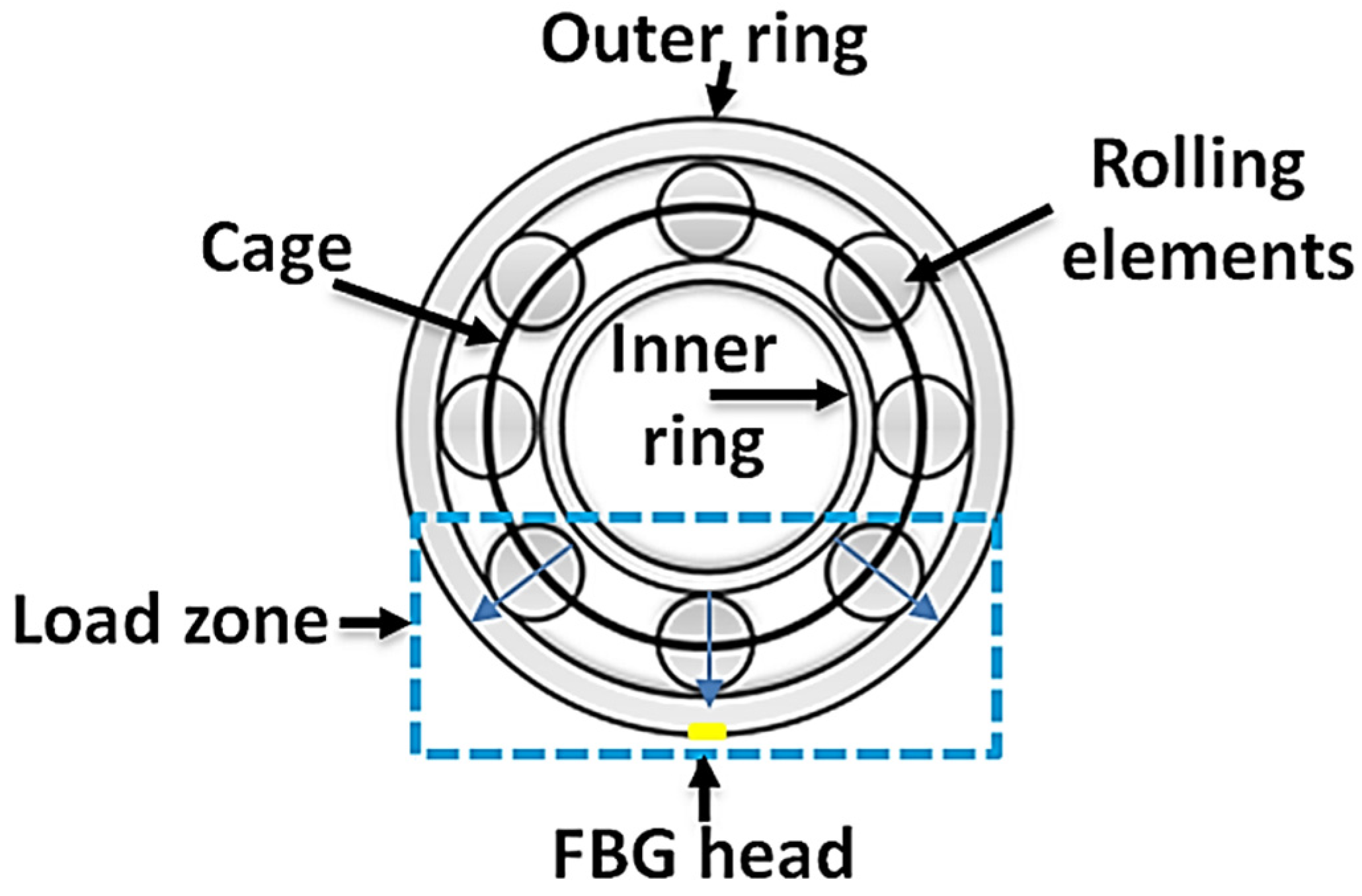
| [38] | A 0.55 kW induction motor | On the outer race bearing | Temperature rises on the healthy and faulty bearings at three different load conditions (no load, half load, and full load) |
| Reference | Type of Electric Machine | Sensor Location | Monitored Magnetic Field |
|---|---|---|---|
| [70] | A 0.75 kW induction motor | In a hole made in the stator core | Air-gap field to monitor broken rotor bars |
| [15] | A 1.1 kW PMSM | On the slot wedge | Air-gap field at different PM rotor demagnetization levels |
| [72] | A 200 MVA hydro generator | On the ventilation ducts of the stator core | Air-gap field to detect inter-turn short circuits of the rotor windings |
| [14] | A single-coil 1.1 kW PMSM | On the slot wedge | Air-gap field at different PM rotor demagnetization levels |
| [73] | A 1.1 kW three-phase induction motor | Above the silicon steel sheet | Stray-flux monitoring during three different fault scenarios on the end-winding |
| Reference | Type of Electric Machine | Sensor Location | Monitored Parameters |
|---|---|---|---|
| [38,39] | A 0.55 kW induction motor | On the end-drive bearing outer race | Thermal and mechanical strain parameters at different load and faulty conditions |
| [36] | A 0.55 kW induction motor | On the rotor bar and the end-ring surfaces | Thermal and mechanical operating conditions |
| [40] | A 15 HP induction motor | On the ball bearing cover | Thermal and mechanical strain for an inner race bearing fault condition. |
| [3,4,5,85] | A 2 kW PM motor | In the stator winding and stator teeth, on the PM rotor, and on the rotor shaft | Thermal profiling, mechanical vibration, and torque. |
| [73] | A 1.1 kW three-phase induction motor | Above the silicon steel sheet | Temperature measurement and magnetic sensing during three fault conditions on the end-winding |
Publisher’s Note: MDPI stays neutral with regard to jurisdictional claims in published maps and institutional affiliations. |
© 2022 by the authors. Licensee MDPI, Basel, Switzerland. This article is an open access article distributed under the terms and conditions of the Creative Commons Attribution (CC BY) license (https://creativecommons.org/licenses/by/4.0/).
Share and Cite
Suryandi, A.A.; Sarma, N.; Mohammed, A.; Peesapati, V.; Djurović, S. Fiber Optic Fiber Bragg Grating Sensing for Monitoring and Testing of Electric Machinery: Current State of the Art and Outlook. Machines 2022, 10, 1103. https://doi.org/10.3390/machines10111103
Suryandi AA, Sarma N, Mohammed A, Peesapati V, Djurović S. Fiber Optic Fiber Bragg Grating Sensing for Monitoring and Testing of Electric Machinery: Current State of the Art and Outlook. Machines. 2022; 10(11):1103. https://doi.org/10.3390/machines10111103
Chicago/Turabian StyleSuryandi, Asep Andi, Nur Sarma, Anees Mohammed, Vidyadhar Peesapati, and Siniša Djurović. 2022. "Fiber Optic Fiber Bragg Grating Sensing for Monitoring and Testing of Electric Machinery: Current State of the Art and Outlook" Machines 10, no. 11: 1103. https://doi.org/10.3390/machines10111103