
Design and Performance Analysis of a Double-Outlet-Rod Magnetorheological Damper for Impact Load

Abstract
:1. Introduction
2. Design of Magnetorheological Damper
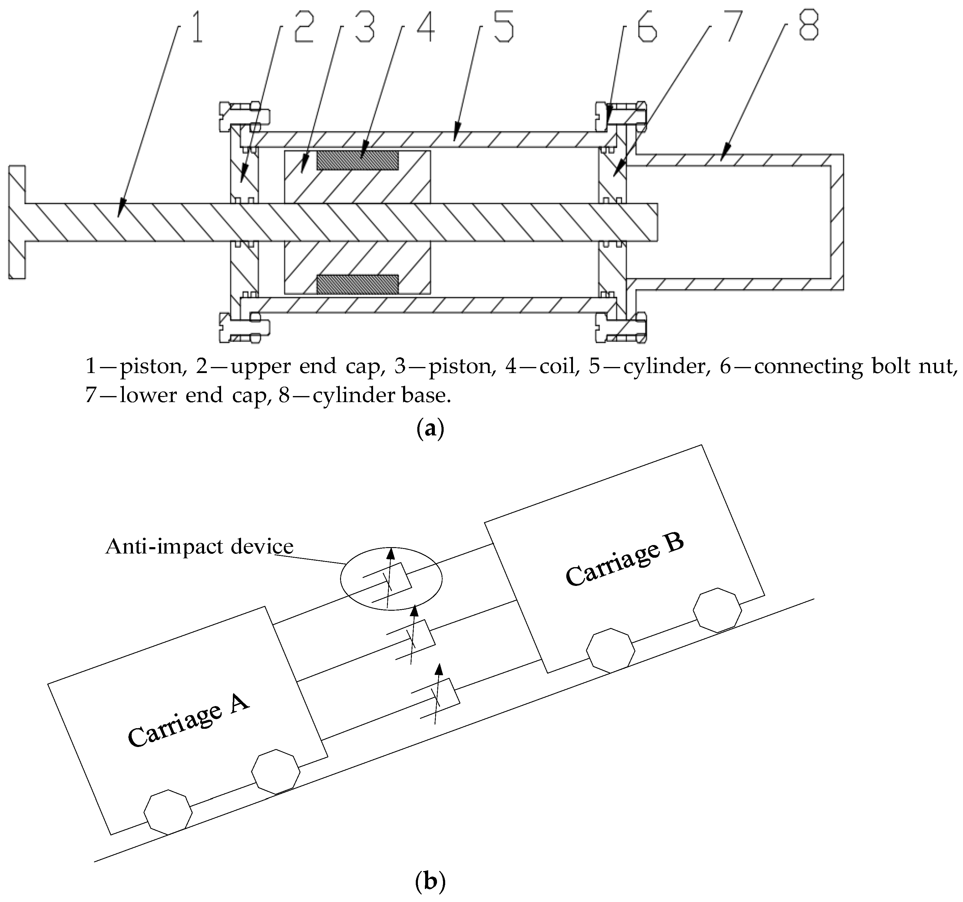
2.1. Structure Design
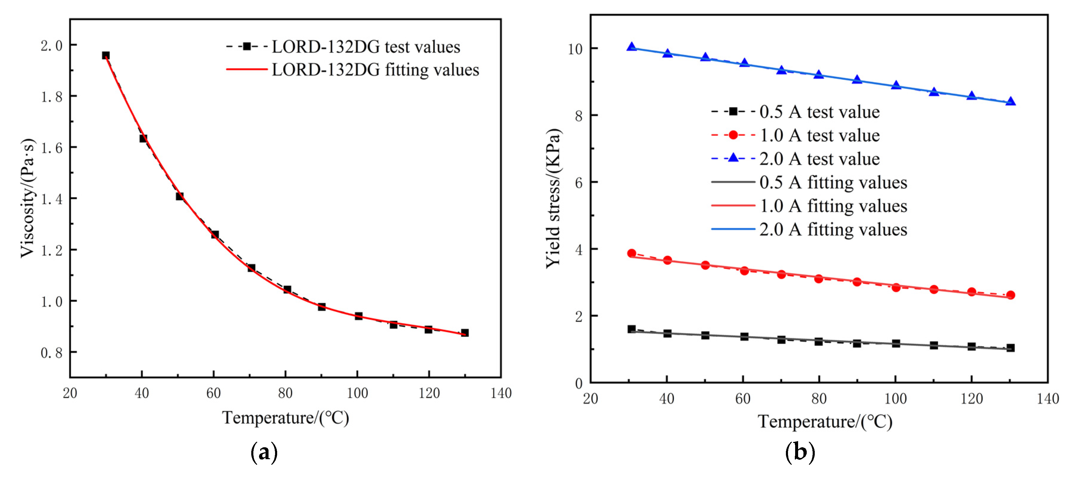
2.2. Characteristics of Magnetorheological Fluid
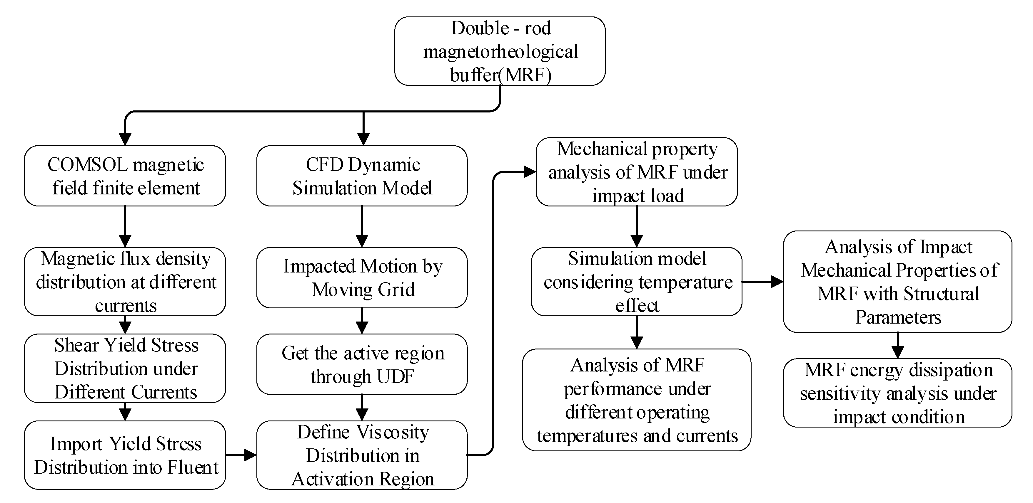
3. Multi-Physical Field Coupling Analysis
3.1. Static Magnetic Field Analysis
3.2. CFD Dynamic Simulation Model
3.2.1. Constitutive Model
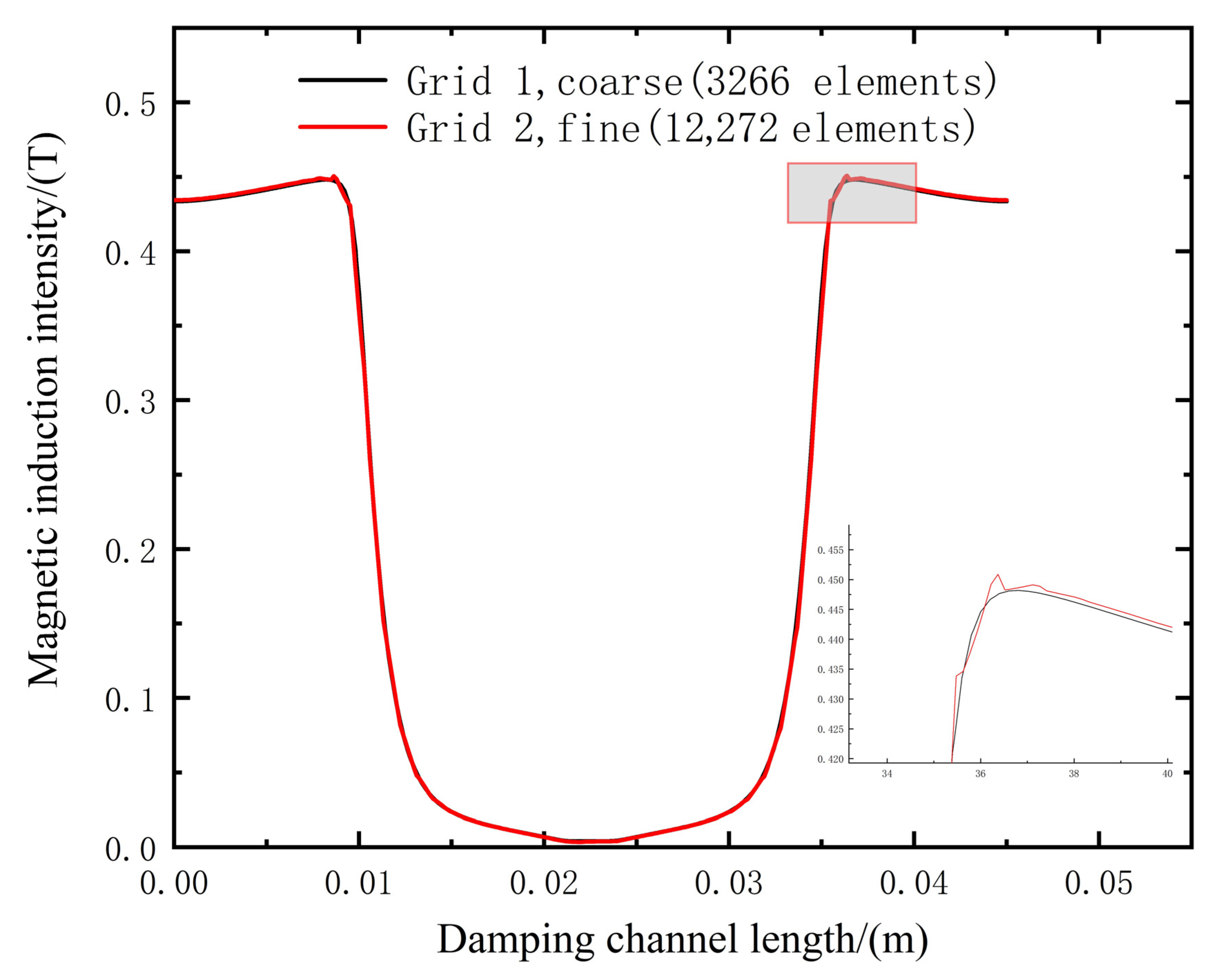
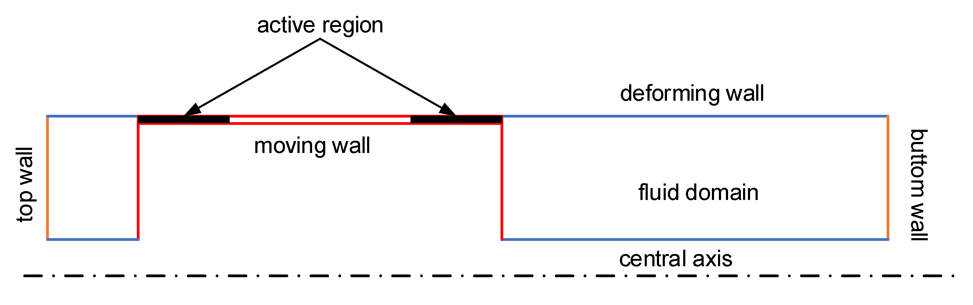
3.2.2. Dynamic Grid Technology
3.2.3. Magnetic-Flow Coupling Analysis Method
4. Multiphysics Simulation of Magnetorheological Damper
4.1. Impact Load versus Quasi-Static Simulation
4.1.1. Quasi-Static Simulation Analysis
4.1.2. Simulation Analysis of Impact Conditions
4.1.3. Proportion of Viscous Damping Energy Absorption
4.2. Effect of Temperature on Mechanical Properties of Magnetorheological Damper under Impact Load
4.3. Effect of Structural Parameters on Impact Performance of the Magnetorheological Damper
4.3.1. Effects of Structural Parameters
4.3.2. Sensitivity Analysis of Structural Parameters
5. Experimental Verification
6. Conclusions
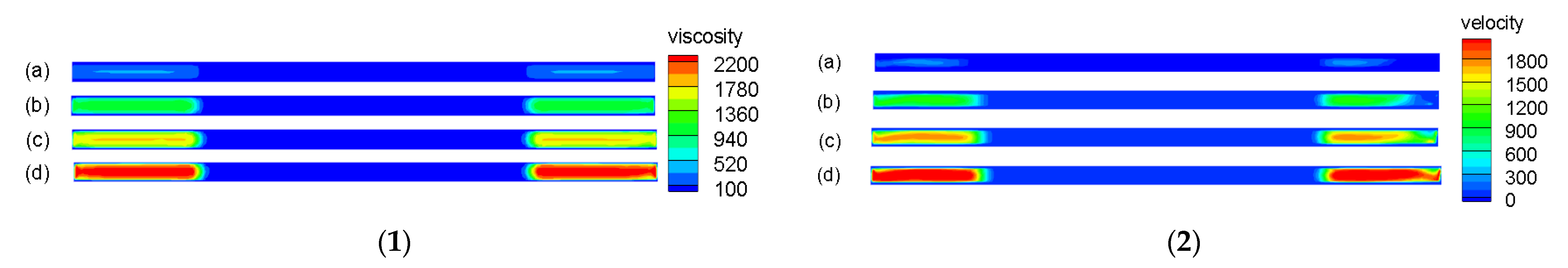
- (1)
- Under impact conditions, the viscosity distribution of the damping channel activation region of the magnetorheological damper is disordered, the region of the structural flow in the semi-solid state is small and the influence of the Coulomb damping force is greatly weakened. When the current is 0.5 A, the viscous damping force accounts for 91.2%, and the viscous damping force plays a major role in buffering and absorbing energy.
- (2)
- With increasing working temperature, the effect of the Coulomb damping force is weakened, and the viscous damping force plays a major role in energy absorption. The peak pressure and impact energy consumption of the magnetorheological damper are greatly reduced. Additionally, this reduction is further increased with increasing excitation current.
- (3)
- The influence of gap height, piston diameter and effective length on magnetic flux density and impact energy dissipation is determined by the peak sensitivity function. When the change in the structural parameters ∆α is 30%, the change in piston diameter has the greatest influence on the peak sensitivity of the magnetic flux density, and the peak sensitivity index of the magnetic flux density reaches 25%. The change in clearance height has the greatest influence on the impact energy consumption, and the peak sensitivity index of the impact energy consumption reaches 115%. This shows that the magnetic flux density is most affected by the piston diameter, and the impact energy consumption is most affected by the clearance height. In the later optimization design of the damper structure, the above parameters can be used as optimization variables by using the NSGA-II algorithm or other multi-objective optimization algorithms to optimize the design.
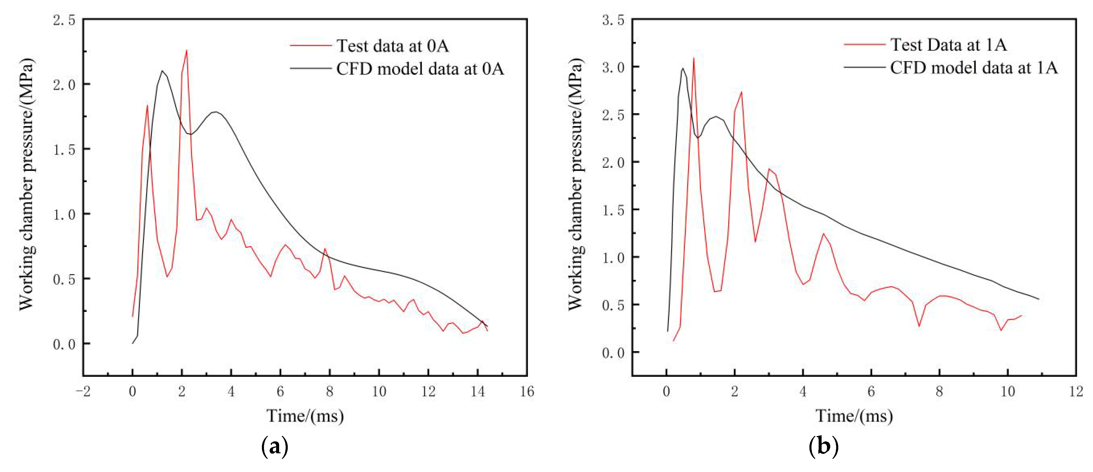
- (4)
- Because the simulation model is more idealized, the friction and the small structure at the inlet and outlet are not considered. The results show that the maximum error of peak pressure is less than 10% in both cases. It can be assumed that this result shows the consistency of the test and simulation trends, which can help us verify that the multi-physical simulation model established in this paper can better reflect the mechanical properties of a real magnetorheological damper.
Author Contributions
Funding
Institutional Review Board Statement
Informed Consent Statement
Data Availability Statement
Conflicts of Interest
References
- Saleh, M.K.; Nejatpour, M.; Acar, H.Y.; Lazoglu, I. A new magnetorheological damper for chatter stability of boring tools. J. Mater. Process. Technol. 2021, 289, 116931. [Google Scholar] [CrossRef]
- Hu, G.; Yi, F.; Tong, W.; Yu, L. Development and evaluation of an magnetorheological damper with enhanced effective gap lengths. IEEE Access 2020, 8, 156347–156361. [Google Scholar] [CrossRef]
- Christie, M.D.; Sun, S.; Deng, L.; Ning, D.H.; Du, H.; Zhang, S.W.; Li, W.H. A variable resonance magnetorheological-fluid-based pendulum tuned mass damper for seismic vibration suppression. Mech. Syst. Signal Process. 2019, 116, 530–544. [Google Scholar] [CrossRef]
- Li, C.; Wang, J. A gun recoil system employing a magnetorheological fluid damper. Smart Mater. Struct. 2012, 21, 105003. [Google Scholar] [CrossRef]
- Zhu, S.; Liu, X. Design and performance analysis of magnetorheological fluid damper for aircraft nose landing gear. Mach. Tool Hydraul. 2019, 47, 65–68+98. [Google Scholar]
- Du, X.; Gan, B.; Jian, X.; Fu, B.; Liu, C.; Liao, C. Design theory and drop impact test of magnetorheological mud buffer considering wall slip. J. Vib. Shock. 2021, 40, 201–208. [Google Scholar]
- Li, Z. Study on Enhancing Efficiency of Radial Flow Magnetorheological Buffer Device; Chongqing University: Chongqing, China, 2018. [Google Scholar]
- Cheng, M.; Chen, Z.; Kyongsol, K.; Jiao, Y. Design and analysis of a multistage serpentine magnetorheological damper. J. Eng. Des. 2017, 24, 350–358. [Google Scholar]
- Yarali, E.; Mohammadi, A.; Mafakheri, S.; Baghani, M.; Adibi, H. Mathematical modeling and experimental evaluation of a prototype double-tube magnetorheological damper. SN Appl. Sci. 2019, 1, 1341. [Google Scholar] [CrossRef] [Green Version]
- Nguyen, Q.H.; Choi, S.B.; Lee, Y.S.; Han, M.S. Optimal design of high damping force engine mount featuring MR valve structure with both annular and radial flow paths. Smart Mater. Struct. 2013, 22, 5024. [Google Scholar] [CrossRef]
- Li, Y. Simulation and Control of Magnetorheological Damper; Nanjing University of Science and Technology: Nanjing, China, 2019. [Google Scholar]
- Elsaady, W.; Oyadiji, S.O.; Nasser, A. A one-way coupled numerical magnetic field and CFD simulation of viscoplastic compressible fluids in magnetorheological dampers. Int. J. Mech. Sci. 2020, 167, 105265. [Google Scholar] [CrossRef]
- Case, D.; Taheri, B.; Richer, E. Dynamical modeling and experimental study of a small-scale magnetorheological damper. IEEE/ASME Trans. Mechatron. 2014, 19, 1015–1024. [Google Scholar] [CrossRef]
- Gurubasavaraju, T.M.; Kumar, H.; Mahalingam, A. An approach for characterizing twin-tube shear-mode magnetorheological damper through coupled FE and CFD analysis. J. Braz. Soc. Mech. Sci. Eng. 2018, 40, 139. [Google Scholar] [CrossRef]
- Parlak, Z.; Engin, T.; Çall, I. Optimal design of magnetorheological damper via finite element analyses of fluid dynamic and magnetic field. Mechatronics 2012, 22, 890–903. [Google Scholar] [CrossRef]
- Huang, T.; Zhou, J.; Xu, Y.; Meng, F. Modeling of magnetorheological damper based on multi-field coupling analysis and influence of structural parameters. J. Zhejiang Univ. (Eng. Sci. Ed.) 2020, 10, 2001–2008. [Google Scholar]
- Liu, X.; Wu, D.; Ma, J. Mechanical performance analysis of magnetorheological damper based on magnetic field FE and CFD. Trans. Chin. Soc. Agric. Mach. 2020, 8, 25. [Google Scholar]
- Elsaady, W.; Oyadiji, S.O.; Nasser, A. Study of failure symptoms of a single-tube magnetorheological damper using an FEA-CFD approach. J. Intell. Mater. Syst. Struct. 2021, 32, 1391–1419. [Google Scholar] [CrossRef]
- Kemerli, M.; Engin, T. Numerical analysis of a monotube mixed-mode magnetorheological damper by using a new rheological approach in CFD. Rheol. Acta 2021, 60, 77–95. [Google Scholar] [CrossRef]
- Hu, G.; Deng, Y.; Yu, L.; Li, G. Multiphysics coupling simulation and dynamic performance analysis of magnetorheological damper. Magn. Mater. Devices 2020, 51, 14–21+66. [Google Scholar]
- Yu, Z. Multi-Field Coupling Analysis and Control System of Magnetorheological Semi-Active Shock Absorber; Jilin University: Changchun, China, 2014. [Google Scholar]
- Zhang, Y. Multi-Field Coupling Analysis and Dynamic Characteristics of Magnetorheological Damper; Yanshan University: Qinhuangdao, China, 2016. [Google Scholar]
- Feng, Z.; Sun, J.; Zhao, H.; Zhang, G.; Wang, L.; Li, H. Dynamics simulation modeling and test of MR Damper under temperature effect. Trans. Chin. Soc. Agric. Mach. 2018, 49, 382–388. [Google Scholar]
- Sherman, S.G.; Powell, L.A.; Becnel, A.C.; Wereley, N.M. Scaling temperature-dependent rheology of magnetorheological fluids. J. Appl. Phys. 2015, 117, 17C751. [Google Scholar] [CrossRef]
- Michael, M.; Faramarz, G.; Wang, X.J. Effects of temperature on performance of compressible magnetorheological fluid suspension systems. J. Intell. Mater. Syst. Struct. 2018, 29, 41–51. [Google Scholar]
- Zarana, L.; Ramesh, V.U. Temperature dependence quasi-static measurements on a magnetorheological fluid having plate-like iron particles as dispersed phase. J. Intell. Mater. Syst. Struct. 2016, 27, 1329–1336. [Google Scholar]
- Hu, H.; Yin, B.; Feng, Z.; Zhang, L. Bouc-wen model of magnetorheological damper considering temperature effect. Ship Eng. 2016, 38, 45–49. [Google Scholar]
- Zheng, J. Research on Key Technology of Impact Resistant Multistage Independent Magnetorheological Buffer; Nanjing University of Science and Technology: Nanjing, China, 2016. [Google Scholar]
- LORD Corporation. Magneto-Rheological (MR) Technological Hydrocarbon-Based Magnetorheological Fluid MRF-132DG Product Bulletin; LORD Corporation: Cary, NC, USA, 2005. [Google Scholar]
- Li, L.; Zou, M.; Ren, S.; Qiao, Y.; Sun, D. Flow field analysis of three-dimensional Lello pump based on FLUENT dynamic mesh technology. J. Chang. Univ. (Nat. Sci. Ed.) 2021, 33, 57–61. [Google Scholar]
- Guan, Z.; Ruan, W.; Tong, Y.; Hao, L.; Meng, W.; Shu, D. Numerical simulation of airborne external weapon separation based on FLUENT software platform. J. Rocket. Guid. 2020, 40, 119–122+134. [Google Scholar]
- Jing, J.; Liu, M.; Li, Y.; Nie, W. Research on buffer characteristics of hydraulic cylinder based on CFD dynamic mesh simulation technology. Fluid Transm. Control. 2015, 3, 37–39. [Google Scholar]
- An, C.; Ma, J.; Wang, J.; Quan, L. Magnetorheological damper output damping force sensitivity analysis. Mech. Electr. Eng. 2018, 35, 1137–1144. [Google Scholar]


| Sign | Name | Parameter/mm |
|---|---|---|
| Outer diameter of cylinder | 50 | |
| Inner diameter of cylinder | 40 | |
| Piston rod diameter | 10 | |
| Diameter of coil skeleton | 27 | |
| Piston bore | 38 | |
| Length of coil skeleton | 25 | |
| Effective length | 10 | |
| Piston length | 45 | |
| Damping clearance | 1 |
| Material | Material Properties | Parameter Value |
|---|---|---|
| MRF-132DG Magnetorheological Fluid [29] | Fluid density | 3200 kg/m3 |
| Off-state viscosity (30 °C) | 0.135 Pa·s | |
| Operating temperature range | −40~+130 °C | |
| Isobaric specific heat capacity | 2100 J/(kg·K) | |
| Thermal conductivity | 0.24 W/(m·K) | |
| Provenance | 5 × 10⁻⁶ S/m | |
| Relative dielectric constant | 2.293 | |
| Yield stress | Formula (3) | |
| B-H curve | Figure 3 | |
| 45# Carbon Steel | Provenance | 4.032 × 10⁶ S/m |
| B-H curve | Figure 3 |
| Current (A) | 10 °C Peak Pressure (MPa) | 50 °C Peak Pressure (MPa) | Peak Pressure Change Rate (MPa/°C) | Peak Pressure Reduction Percentage (%) |
|---|---|---|---|---|
| 0 | 2.78 | 1.33 | 0.036 | 52 |
| 0.5 | 3.05 | 1.37 | 0.042 | 55 |
| 1 | 3.88 | 1.50 | 0.059 | 61 |
| 2 | 5.46 | 1.78 | 0.092 | 67 |
| Current (A) | 10 °C Impact Energy Dissipation (J) | 50 °C Impact Energy Dissipation (J) | Rate of Change in Impact Energy Consumption (J/°C) | Percentage Reduction in Impact Energy Consumption (%) |
|---|---|---|---|---|
| 0 | 33.17 | 16.73 | 0.41 | 49.6 |
| 0.5 | 39 | 17.55 | 0.54 | 55 |
| 1 | 47.27 | 18.83 | 0.71 | 60.2 |
| 2 | 57.09 | 21 | 0.9 | 63.2 |
Publisher’s Note: MDPI stays neutral with regard to jurisdictional claims in published maps and institutional affiliations. |
© 2022 by the authors. Licensee MDPI, Basel, Switzerland. This article is an open access article distributed under the terms and conditions of the Creative Commons Attribution (CC BY) license (https://creativecommons.org/licenses/by/4.0/).
Share and Cite
Wang, C.; Zhang, J.; Liu, G.; Shang, H.; Wei, X. Design and Performance Analysis of a Double-Outlet-Rod Magnetorheological Damper for Impact Load. Machines 2022, 10, 1099. https://doi.org/10.3390/machines10111099
Wang C, Zhang J, Liu G, Shang H, Wei X. Design and Performance Analysis of a Double-Outlet-Rod Magnetorheological Damper for Impact Load. Machines. 2022; 10(11):1099. https://doi.org/10.3390/machines10111099
Chicago/Turabian StyleWang, Chenglong, Jiwei Zhang, Guoming Liu, Huan Shang, and Xueqian Wei. 2022. "Design and Performance Analysis of a Double-Outlet-Rod Magnetorheological Damper for Impact Load" Machines 10, no. 11: 1099. https://doi.org/10.3390/machines10111099