Article

A Novel Computational-Based Visual Brand Identity (CbVBI) Product Design Methodology

by
Athanasios Manavis
1,*,
Anastasios Tzotzis
1,
Apostolos Tsagaris
2 and
Panagiotis Kyratsis
1,*
1
Department of Product and Systems Design Engineering, University of Western Macedonia, GR50100 Kila Kozani, Greece
2
Department of Industrial Engineering and Management, International Hellenic University, GR57400 Thessaloniki, Greece
*
Authors to whom correspondence should be addressed.
Machines 2022, 10(11), 1065; https://doi.org/10.3390/machines10111065
Submission received: 6 October 2022 / Revised: 28 October 2022 / Accepted: 8 November 2022 / Published: 11 November 2022
(This article belongs to the Special Issue Design and Manufacturing: An Industry 4.0 Perspective)

Abstract

:
Product design is a promising field for the application of new technologies and methodologies emerging from the digital evolution of Industry 4.0. A great number of tools have been developed in order to accentuate the use of modern Computer-Aided Design (CAD) systems and computational design techniques for design customization in product applications. The present paper deals with the development of two different applications for designing furniture based on the Computational-based Visual Brand Identity (CbVBI) design methodology. For the first case study, the Application Programming Interface (API) SolidworksTM (VBA event-driven programming language) is used. The second case study focuses on the visual programming language of GrasshopperTM, which is incorporated within Rhinoceros3DTM. The proposed case studies offer a great deal of flexibility in both design and manufacturing, while many design alternatives could become available in a very short period.

1. Introduction

Automated product design is a topic receiving increasing interest from both industry and academia. Modern industries tend to automate every aspect related to the development of a consumer product. Hence, the conceptual design, the testing and the finalization of a product are only some of the processes considered for automatization. An Application Programming Interface (API) in CAD systems is a tool that can facilitate the realization of the aforementioned tasks. Parallelly, computational design affords a great number of benefits to CAD systems that can level up common CAD-based design procedures. Specifically, computational design is a novel strategy of using visual programming aspects to create and transform shapes, forms and structures. This allows the end-users to act as co-designers and take part in creating alternative options for the original products. Finally, the increase in the productivity and the automation of daily routines has enabled designers to effectively allocate their time to more creative tasks.

2. State of the Art

2.1. Automated Product Design and Mass Customization

CAD-based programming is commonly used for the simulation of several industrial processes, such as the kinematics of machining and robotics, the prediction of machining components, the extraction of manufacturing data [1,2,3,4], measurements, quality assessment [5,6] and many more. The computational design methodology derives from similar procedures in mass customization. The usability of these techniques has been expanded to multiple fields of application, such as the design and assembly of products, which is the topic of the two case studies presented in this article, the generation of engineering drawings and assembly instructions and high-quality renderings and illustrations.

2.2. CAD-Programming Design and APIs

Tzotzis et al. [7] and Kyratsis et al. [8] used similar techniques to develop applications for the automated accomplishment of a set of engineering processes related to the development of standardized mechanical parts and systems. Hong et al. [9] managed to simplify the assembly process of complex systems, optimizing in this way the time-consuming and resource-intensive tasks that are required for the assembly of such parts. The majority of the case studies from the proposed references list that are related to the design and assembly of consumer products [10] include the use of material textures, coloring and high-quality renderings that provide the consumer with a complete experience regarding the presentation of the product, as well as its framework. CAD-based programming can be applied to finite element modeling as well.
A number of studies [11,12] exist in the literature in which the automated design of machine tools was realized with the aid of CAD-based coding. The implementation of such techniques can lead to the generation of tool models that can be imported to finite element analysis (FEA) software for simulation purposes. Finally, the work of Nam et al. takes a different approach to programming in relation to CAD systems [13]. The authors developed a web-based material database aiming at the facilitation of the material selection process with respect to the functionality, the manufacturability and cost of the designed product.

2.3. Graphical Algorithmic Design and Web-Based APIs

Castro e Costa et al. [14] proposed an online application that promotes the development of a parametric design system for the mass customization of ceramic tableware. The implementation of the final digital 3D forms accelerated with the use of shape grammar rules according to the specific parametric procedure of computational design. Manavis and Kyratsis [15] managed to blend the principles of brand product identity with the automated procedures of computational design. Specifically, the authors presented a web-based application for the re-creation of novel souvenirs under the umbrella of the “Cycladic marble figurines from the Early Ages” concept. The whole process of the previous application was based on the Computational-based Visual Brand Identity (CbVBI) strategy. Furthermore, Kyratsis et al. [16] defined a unique non-conventional procedure for the form generation of furniture and decorative artifacts. The proposed procedure was based on graphical algorithmic design rules. More specifically, the crucial rules of the aforementioned case study are linked to the morphology and shape parametrization of the produced furniture and decorative artifacts. The proposed approach concerns an ergonomic point of view of product development. Finally, the ChairDNA Design Tool [17] is a great example of a mass customization procedure for product design under the influence of computational design parameterization.

2.4. Product Design as Brand Element

The “product shape generation to support brand identity elements” [18] relates to CbBVI design strategy. The current CbVBI model tries to effectively offer an automatic way of designing alternative products under a specific brand (e.g., morphological specifications, aesthetic criteria, etc.). This unique CbVBI methodology approach connects two different design areas according to state-of-the-art research. Specifically, CbVBI methodology is a bridge between the different design areas of branding and product design under the main design procedure.
The present paper introduces two case studies based on the programming of CAD systems, namely SolidWorks™ (Dassault Systèmes SE, Vélizy-Villacoublay, France) and Rhinoceros3D™ (Robert McNeel & Associates, Seattle, WA, USA). In the first case study, an API is utilized to develop an application for the automated design and assembly of a piece of furniture with a wide range of options that can be commercially distributed. The application comprises three tabs, one for the design options, one for the material selection and one for the product summary and preview, so that the user can select the desired dimensions and construction options, the colors and materials, as well as obtain an instant cost estimation. The second application deals with the design of a desk workstation. Specifically, it introduces a web-based application that offers specific brand parameters to end-users, allowing them to design their own version of the prototype desk workstation. The parameters are related to the main ontology of the desk, e.g., dimensions, materials and colors. The development of the application is based on both the Rhinoceros3DTM and the GrasshopperTM software.

3. The Proposed CbVBI Methodology

Figure 1 illustrates the proposed CbVBI design methodology used to create specific branded pieces of furniture. The workflow is divided into three different sections. The first section of CbVBI deals with the branding elements and references specification. The Do-It-Yourself (DIY) branding theme relates to the furniture ontology (e.g., dimensions variables, design, assembly parts, etc.) [19]. The implementation of the design procedure forms part of the second section of the workflow. More specifically, the second step is composed of two parallel directions: (a) designing with CAD programming tools (textual programming) and (b) designing with computational tools (graphical algorithmic design). These directions are considered in the following procedure according to the digitalized furniture design parametrization: (a) the designer creates the design options according to the furniture ontology, which is related to the object’s morphology, and (b) a material database is created by the designer in order to offer the aesthetic parameters in the design procedure of customizing DIY furniture with a 3D-rendered representation. The final section involves the digital export of the new furniture ideas created from the end-users’ point of view (e.g., rendered images, assembly instructions, etc.). The basic objectives of the CbVBI methodology (as the final result of the research) are summarized in three specific directions: (a) the parametrization of the branding criteria (visual elements), (b) the digitalization of the product development according to computational strategies and finally, (c) the automatization of the product development.

4. Case Studies and Applications

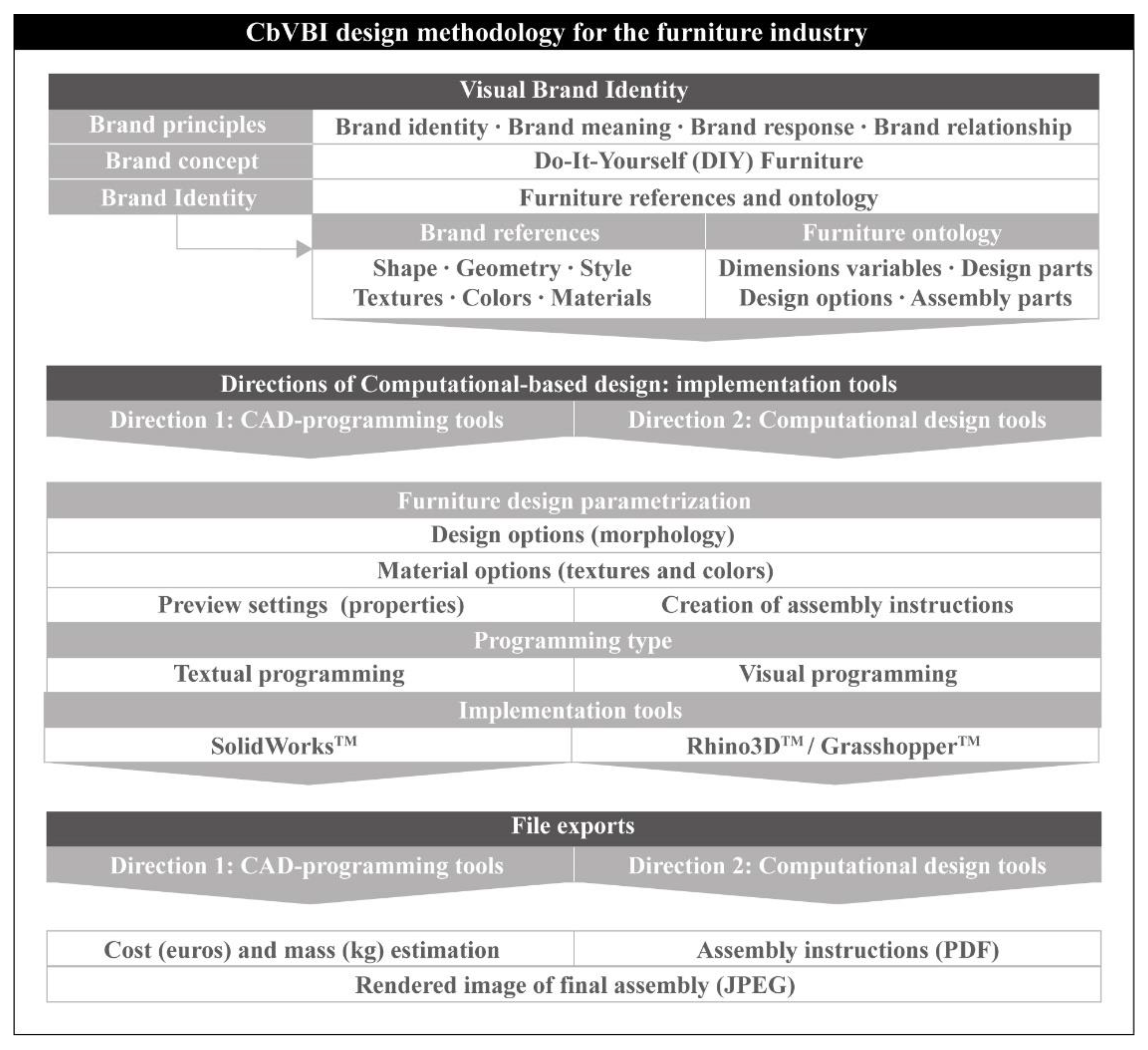
4.1. CAD-Based Design and Assembly of a DIY Coffee Table

Engineering task automation is a key factor in the effective allocation of working time and the creativity of engineers. In particular, design and assembly are two important stages during the development of a product that benefit greatly from such techniques. It is seen more often than not that companies implement CAD-based automation in their projects with the aim of increasing their productivity.
In this case study, a typical example of CAD-based programming is presented, in relation to the design and assembly of a coffee table. Such furniture is common in coffee shops and cafeterias, as well as in similar shops. Despite the fact that this paper does not focus on the design aspect of the product, but rather on the implementation of CAD-based programming for the design procedures, it must be noted that these tables are usually compact, lightweight, somewhat tall and sturdy to allow them to be carried easily, take up only a small area and provide adequate ergonomics for the user. The user interface is considered to be the bridge between the user and the CAD system [20]; therefore, it is important that it is clear and understandable, as well as easy to navigate.
The application is divided into three tabs, as seen in Figure 2. The first tab “Morphology” includes all the necessary fields and lists, where the user can input the dimensions of the table and select the model as well, which corresponds to three different board shapes (rectangle/square, circle and rhombus) and three different chassis types. These parameters yield nine unique table combinations. In addition, the variety of the board materials and colors hugely increases the number of possible combinations. The second tab, namely “Material/Color”, includes a number of buttons, which are used to select one of the available materials and colors.
Additionally, an option is included for a glass board, instead of a wooden one. Furthermore, the user can select the chassis material in this tab, ranging from plain steel for a more economic final product to aluminum, which offers a more stylish look and a lightweight final product. The third tab (Summary) provides the user with auxiliary functions, such a preview of the final product, its weight and cost, as well as a summary of its basic attributes (material, color and dimensions).
The application can be operated with the three command buttons “Design model”, “Rendering” and “Open files”, found in the first tab, which are used to perform the complete design and assembly process, the generation of a rendering of the final product and the compiling of a folder containing the files, respectively.
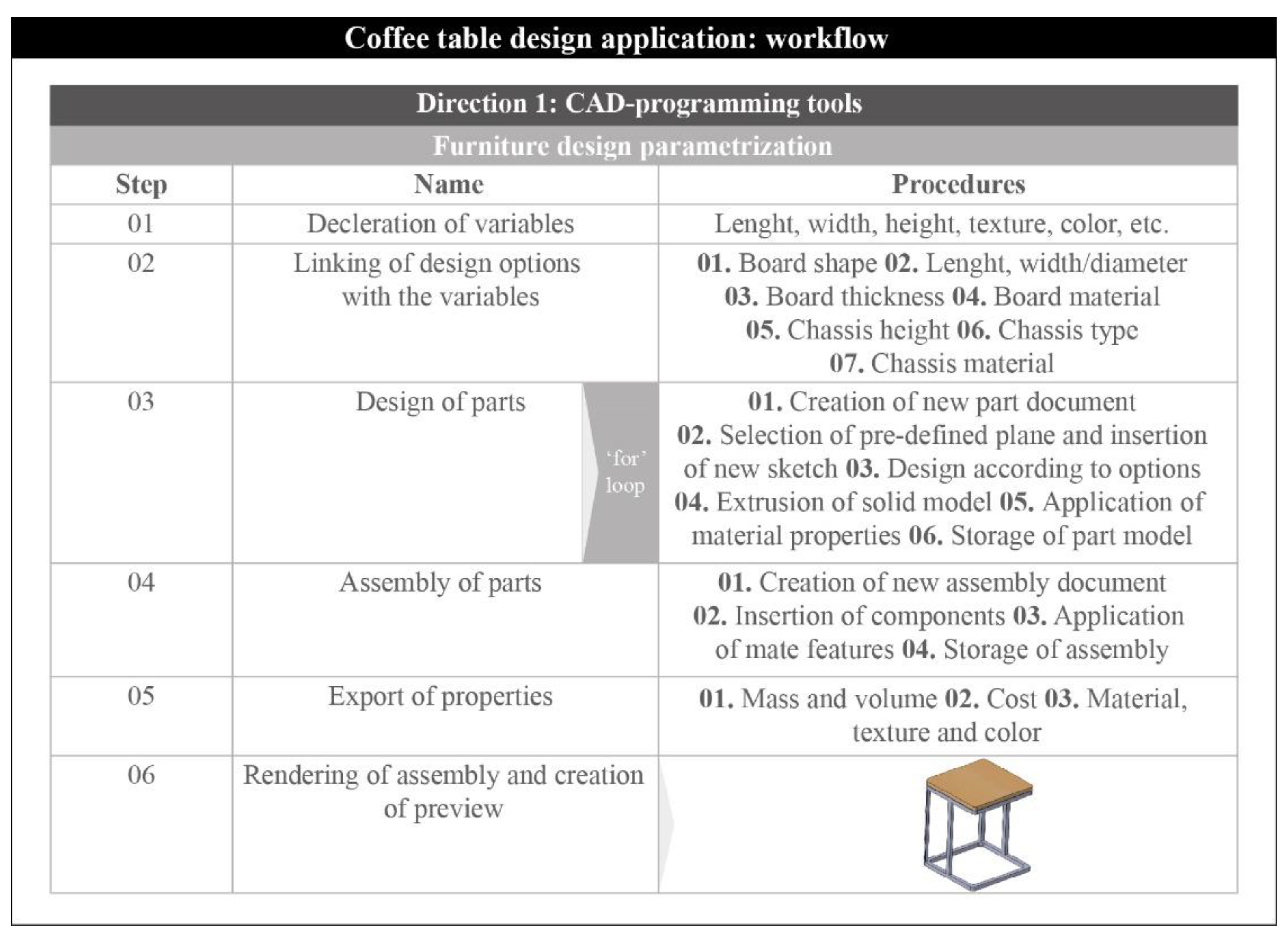
According to Figure 3, the code follows a straightforward execution. First of all, the necessary variables, relating to the dimensions, the material and the color, are declared. Next, these variables are linked to the corresponding design options that are available in the interface. For instance, when the user types a number in the “Length (mm)” field, the variable that corresponds to the length of the board changes its value to the typed one. As soon as the user pushes the “Design model” button, the design process begins. Therefore, the design loop is executed for every part comprising the table. This number varies depending on the selected design options. Regarding the design procedure, the creation of a new part document, the selection of a plane, the insertion of a new sketch, the design of a contour, the extrusion of a solid model, the application of a material texture/color and the storage of the model are tasks that are performed on every iteration of the loop. The only difference is that the contour sketched on each iteration varies according to the part being designed. Hence, a rectangle/square, a rhombus or a circle will be sketched for the design of the board. Similar shapes will be sketched for the design of the chassis parts. To facilitate the design code for the sketched contours of the parts, the “If-Then-Else” structure was used.
The assembly procedure is carried out in a similar manner. Thus, a loop is utilized to repeat the execution of the assembly code. First of all, a new assembly document is created; next, the components comprising the assembly are inserted; and finally, the appropriate mates are applied to the components. In contrast to the design process, the loop only contains the mates, rather than the whole process. With the completion of the assembly, several useful properties, such as the cost, the mass and the volume, are automatically exported to the fields that are available under the “Summary” tab in order to inform the user.
Finally, it is possible to generate a rendering of the final product by pressing the “Rendering button” found under the first tab. The image is saved in a standard image format, JPG. An image showing the user a preview of the final product is automatically generated as soon as the rendering is complete. This way, the user acquires a complete view of the full product.
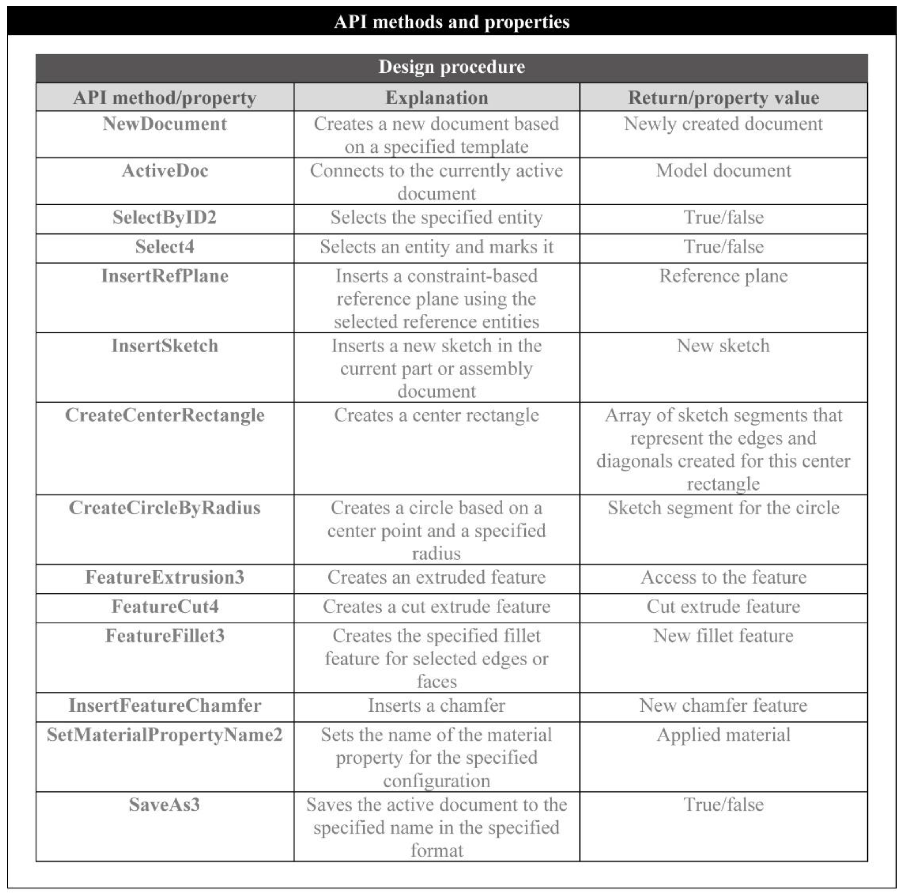
The two first steps of the workflow do not require any special API methods, but rather standard VBA™ statements. The methods and the properties used in the step where the design of the parts is performed are summarized in Figure 4. Most of the methods in the VBA™ language are self-explanatory, and the syntax requires a number of elements that fully define a method, function or statement. Therefore, for the design process, the “SelectByID2” method is used to select named entities, such as edges and faces and especially planes, for sketching. The “InsertRefPlane” method is used to create a number of extra planes on the designed parts that can be used later during the assembly process.
The “InsertSketch” method enables the sketching of a plane, whereas the “CreateCenterRectangle” and the “CreateCircleByRadius” are used to sketch a rectangle/square and a circle, respectively. Additional methods of the same type are available for the sketching of lines, polygons and other shapes. Once the contour is sketched, the “FeatureExtrusion3” and the “FeatureCut4” methods can be utilized to generate solids. With the appropriate syntax, it is possible to create a variety of solids representing the individual parts of the assembly, which can then receive attributes such as mass, volume, texture, color and other visual and physical properties. “SetMaterialPropertyName2” is a method utilized to apply a material name to a part, conferring on it various properties that correspond to the material.
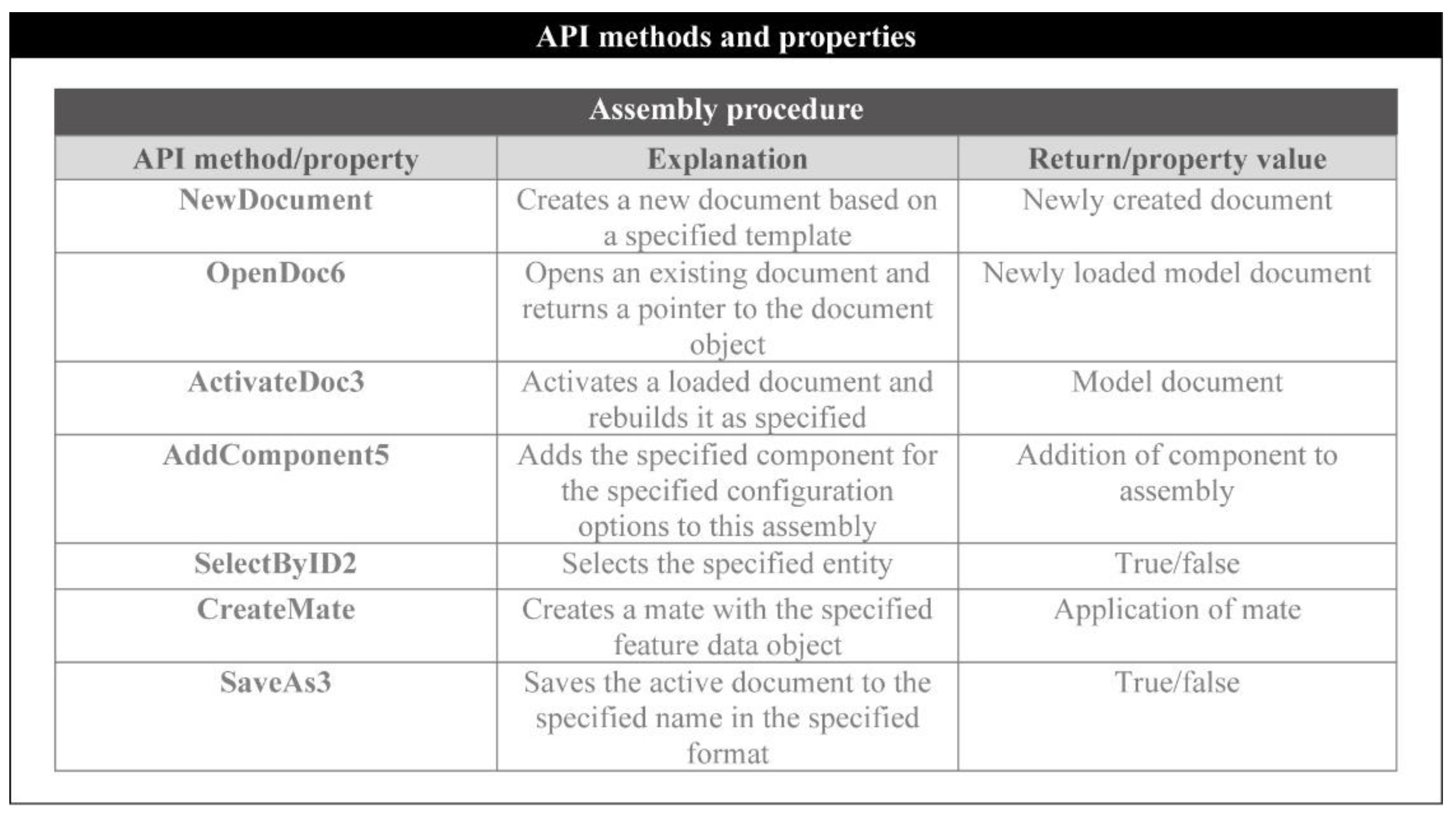
During the stage of the assembly process, a new assembly document is opened and all the parts that comprise the assembly are opened in the background. The “ActivateDoc3” and the “AddComponent5” methods are responsible for the activation of the newly created document and the insertion of each one of the opened parts into this document. “SelectByID2” is used in this stage as well for the same purpose: to select the already named entities for the application of the mate features with the “CreateMate” method. As has been already discussed, it is important that the parts are designed with predefined planes and other geometric entities in order to facilitate the mating process during the assembly of its components. The most commonly used API methods are shown in Figure 5.
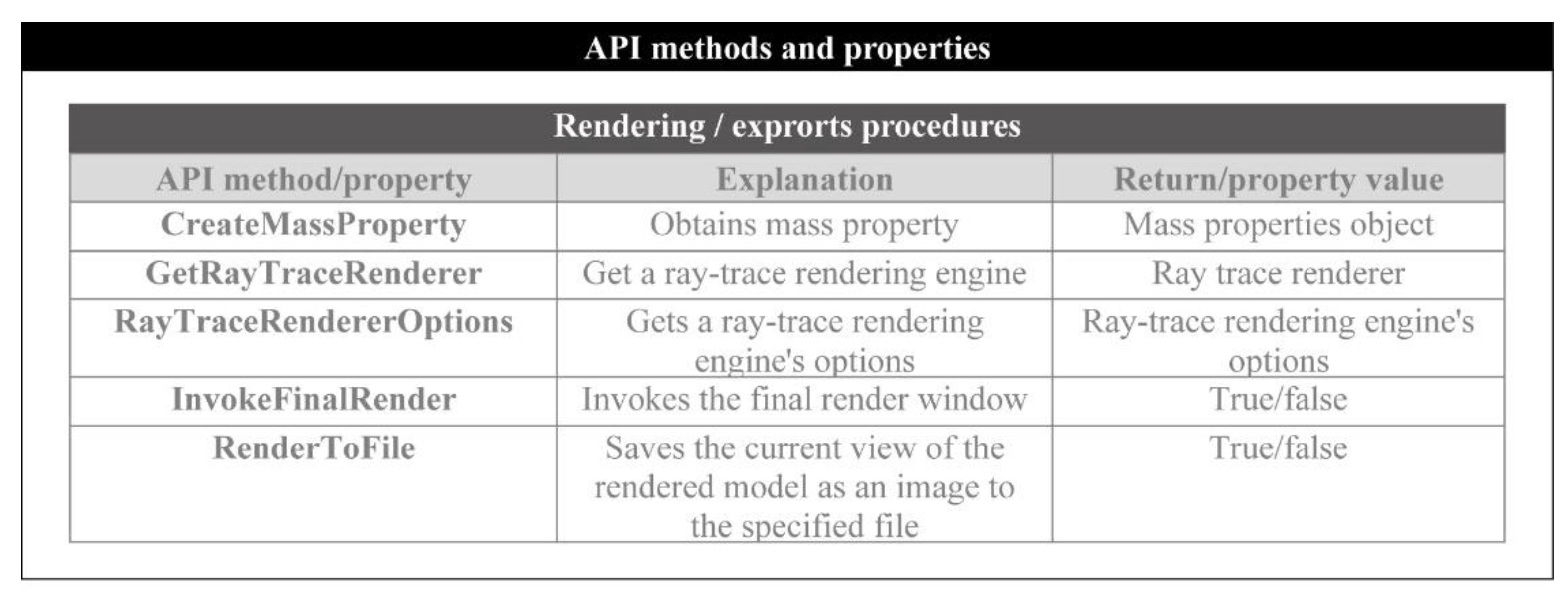
Figure 6 includes the necessary methods and properties for the export of the product’s properties, as well as the realization of the rendering. The method “CreateMassProperty” calculates the mass and volume of an individual part or an assembly by utilizing the physical properties of the applied material. Therefore, this method functions only if a material is set for each of the components.
Moreover, to carry out the rendering, “GetRayTraceRenderer” enables the use of the renderer that is available in the CAD system, whereas the “RayTraceRendererOptions” property sets the rendering options, such as image resolution, dimensions and format. The final rendered image of the product is generated and stored with the methods “InvokeFinalRender” and “RenderToFile”, respectively.
The previous code snippet (Figure 7) presents the lines required for the design of a rectangular board, including the creation of a new part document, the selection of a plane, the insertion of a new sketch, the sketch of rectangle, the extrusion of the sketch and the application of the texture and color of a material. The choice of material is not only important for cosmetic purposes; it is also necessary for the extraction of the physical properties.
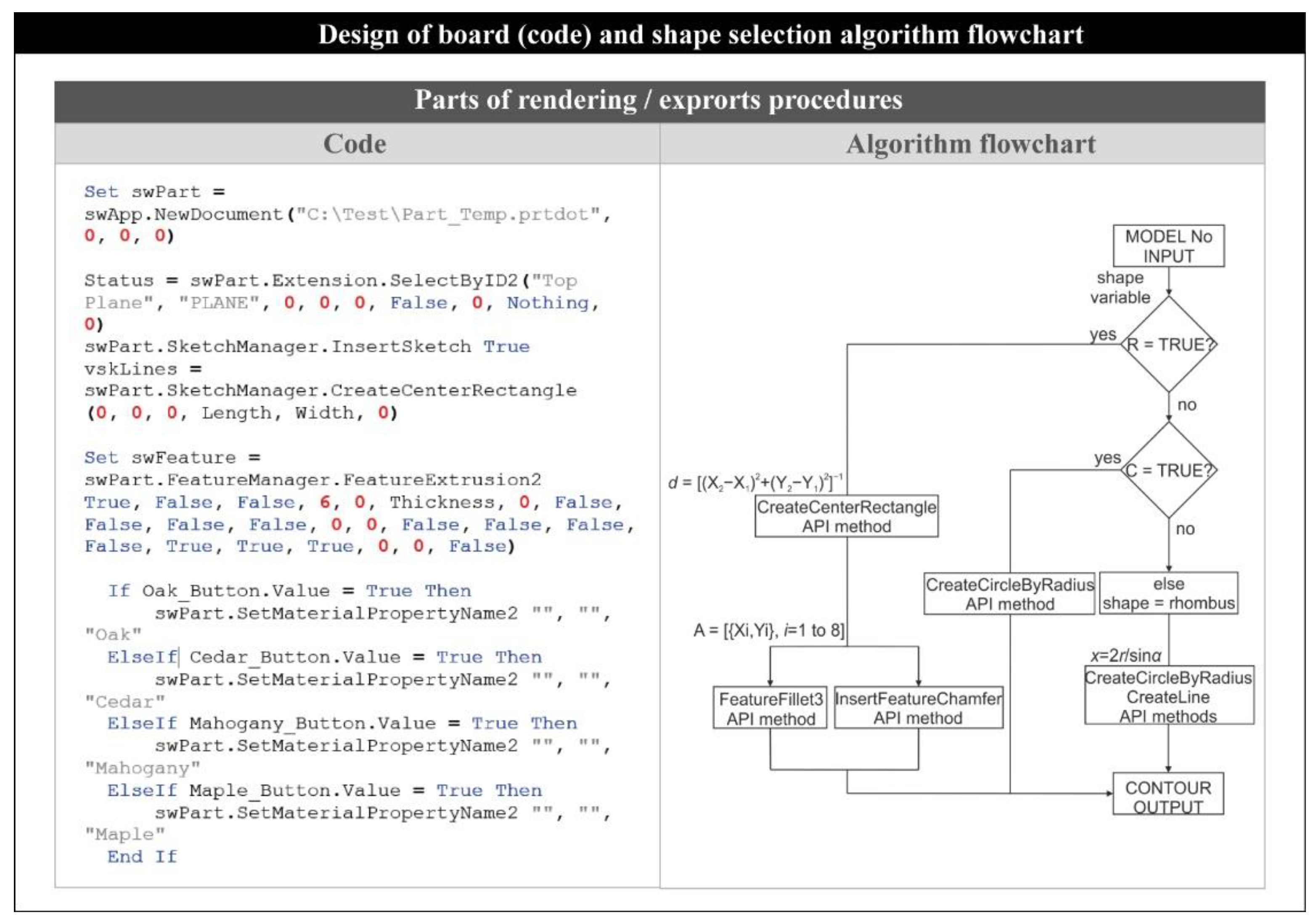
As soon as the user selects a model number, an algorithm (Figure 7) performs a check on the shape of the table so that the geometric measurements can be applied accordingly. If the user inputs dimensions that correspond to a rectangle or a square, the algorithm uses the corresponding API method to generate a rectangle or a square using the diagonal d = x 2 x 1 2 + y 2 y 1 2 1 . Next, the fillet or the chamfer feature is applied based on the model selection. A matrix containing the coordinates (x, y) of the eight points comprising the four chamfered or filleted corners of the rectangle or square is used for the application of the equivalent feature. In the case of a circular table, the algorithm skips the rectangular or square shape and sketches a circle instead via the respective API method, whereas in the case of a rhombic table board, the methods used to sketch a circle and a set of lines are used. Therefore, if the selected model corresponds to a circular board, a circle is sketched with a radius equal to the width given by the user. Finally, the lines are sketched tangential to the circle, forming a tangential quadrilateral with an edge length equal to x = 2 r / s i n a .

4.2. Graphical Algorithmic Design and Assembly of DIY Desk Workstation

Graphical algorithmic editors are important for developing parametric designs through visual programming [21]. The numerous designs that are generated by the proposed CbVBI application are digital forms of a desk workstation. This procedure was based on GrasshopperTM and Rhinoceros3DTM software in order to offer a fully useful design application for branded furniture under the concept of DIY [22].
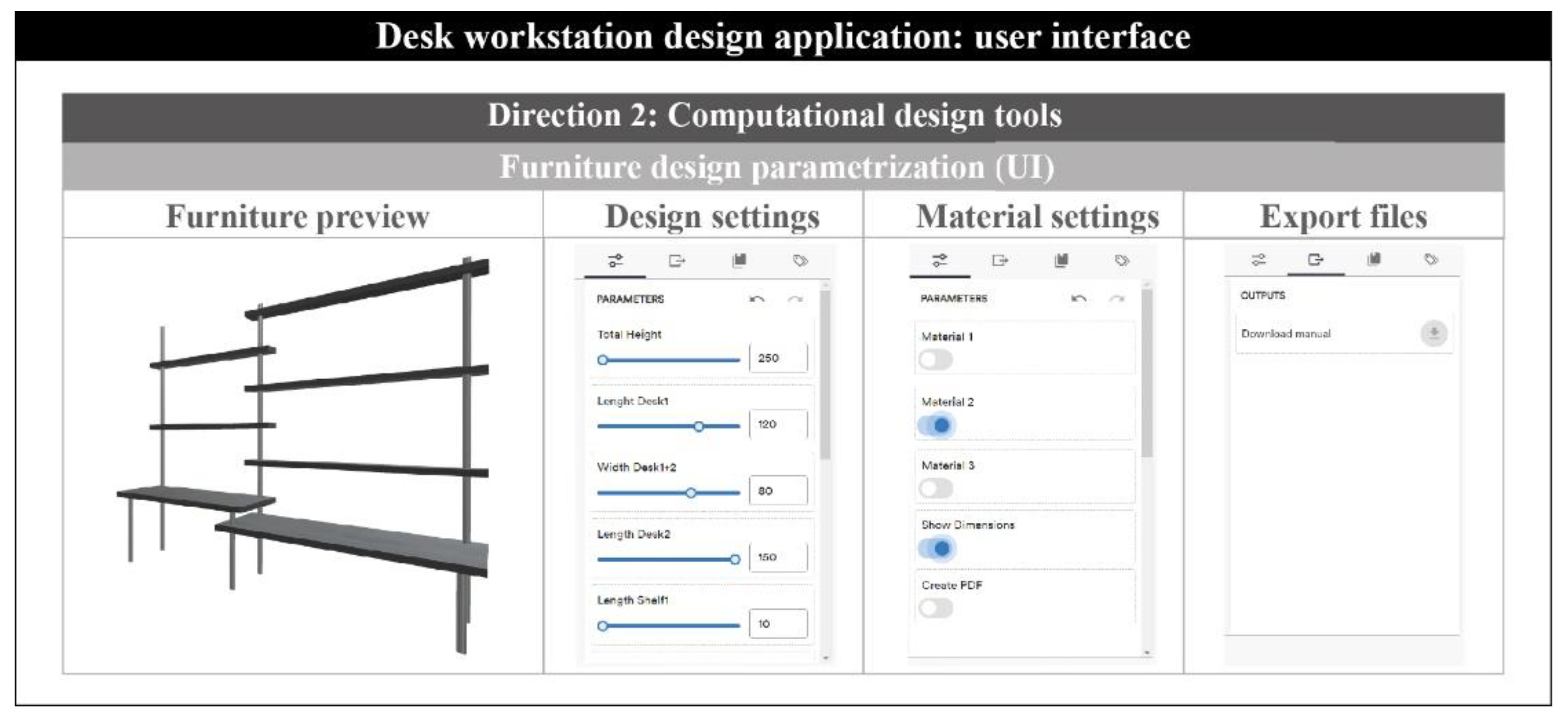
The present application is divided into three different design areas, as seen in Figure 8. The first area includes all the important parameters according to the design options (e.g., basic dimensions of the furniture, number of parts, etc.). Some of the design options are the total height of the product (TH), the length and the width of Desk1&2 and the number of the shelves (LS1 to LS5). Similar to the previous case study, the second area includes a number of options for the material and texture of the furniture. All the materials and skin types are related to wood textures. Finally, the third area provides the export files for the assembly instructions and the rendered representations of the final DIY furniture.
The proposed application was developed with the web-based platform Shape DiverTM. Shape DiverTM allows end-users to design their own objects under specific parameters, which are developed from the programmer/designer’s point of view.
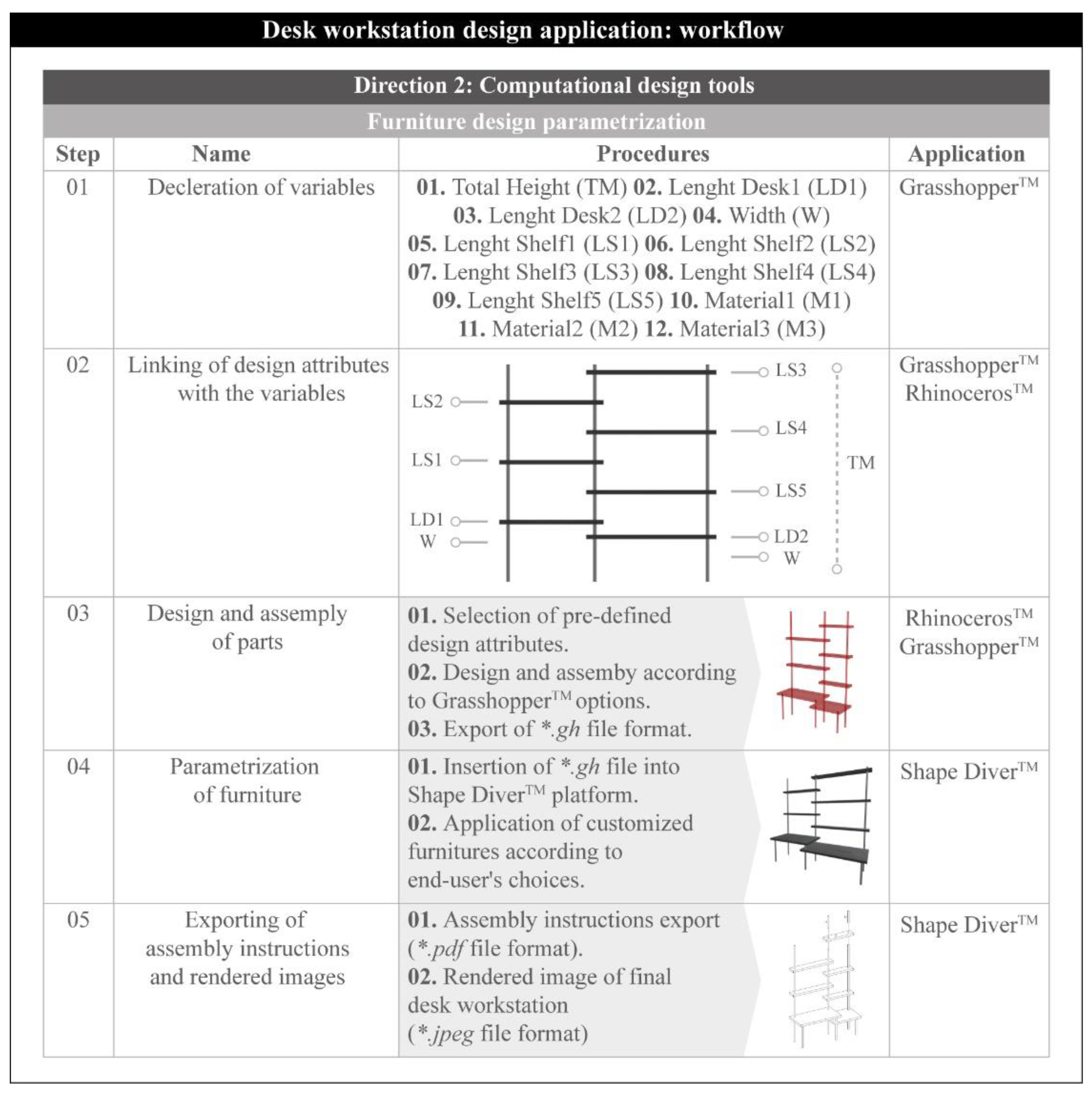
Figure 9 depicts the design procedure for the computational-based visual code, which follows a specific hierarchy of steps. Every step of the proposed workflow is related to a specific node in the graphical algorithm of the whole code. The algorithm has five significant steps/nodes:
  • First of all, the necessary variables relating to the dimensions and colors are declared.
  • Next, these parameters are linked to the corresponding design options. Every aesthetic design criterion is related to a specific variable of the visual programming code.
  • Following this, the third part of total hierarchy is the visual representation of the produced parts of the furniture. With both GrasshopperTM and Rhinoceros3DTM, a final assembled desk is produced with all the design and manufacturing attributes. As a result of the third step, the application is capable of exporting a *.gh file with all the variables and parameters of the design object.
  • The fourth stage of the workflow involves the linking procedure of the *.gh file within the web-based platform Shape DiverTM. At this stage, the programmer/designer organizes the application interface for the furniture parametrization.
  • Finally, the end-user is able to create his own desk workstation according to the “Do-It-Yourself” brand identity. In this case, the user has the responsibility of filling out all the variables in the online CbVBI application.
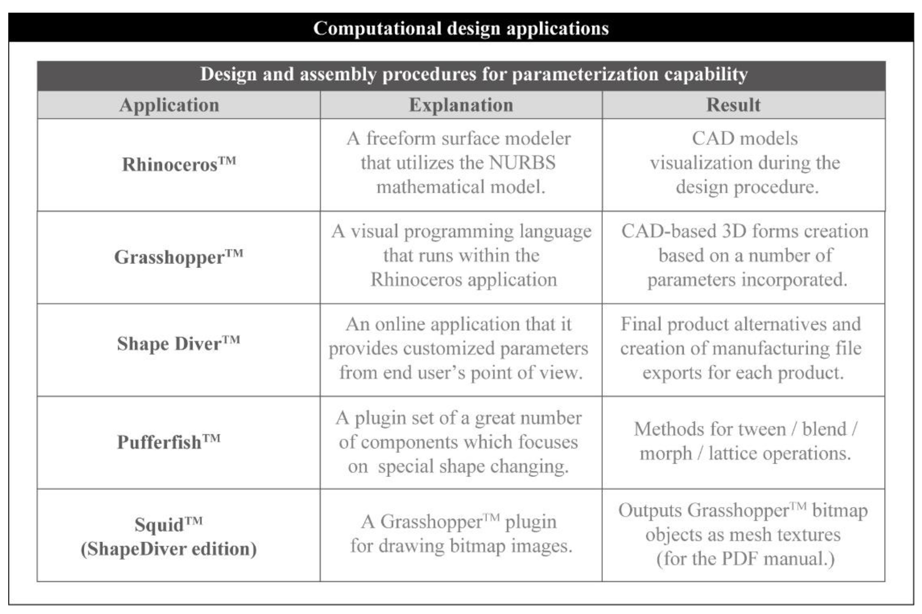
Figure 10 summarizes the group of the applications, pieces of software and add-ons that were used for the development of the CbVBI application. Apart from the aforementioned software GrasshopperTM, Rhinoceros3DTM and Shape DiverTM, the authors used two kinds of special add-ons for the application implementation.
PufferfishTM is a plugin set with a great number of components relating to shape transformations (e.g., tween, blend and morph operations). Additionally, SquidTM is an important plugin for drawing bitmap images. This is a crucial code operation for the final export of the assembly instructions in a PDF file format. Specifically, SquidTM outputs GrasshopperTM bitmap objects as mesh textures in order to represent the final object’s morphology as an image.
According to the previous procedure, the end-user is able to create his own desk workstation following the DIY brand identity principles. Specifically, the designer has the responsibility of filling all the numerical values for the design and material settings in the online application of Shape DiverTM. The proposed Computational-based Visual Brand Identity (CbVBI) methodology exports two types of files in order to support the development of specific applications (e.g., technical drawings and assembly instructions). Finally, the production of the rendered images is based on the main characteristics of rendering synthesis: materials, textures, shadows, lights and the environment elements.
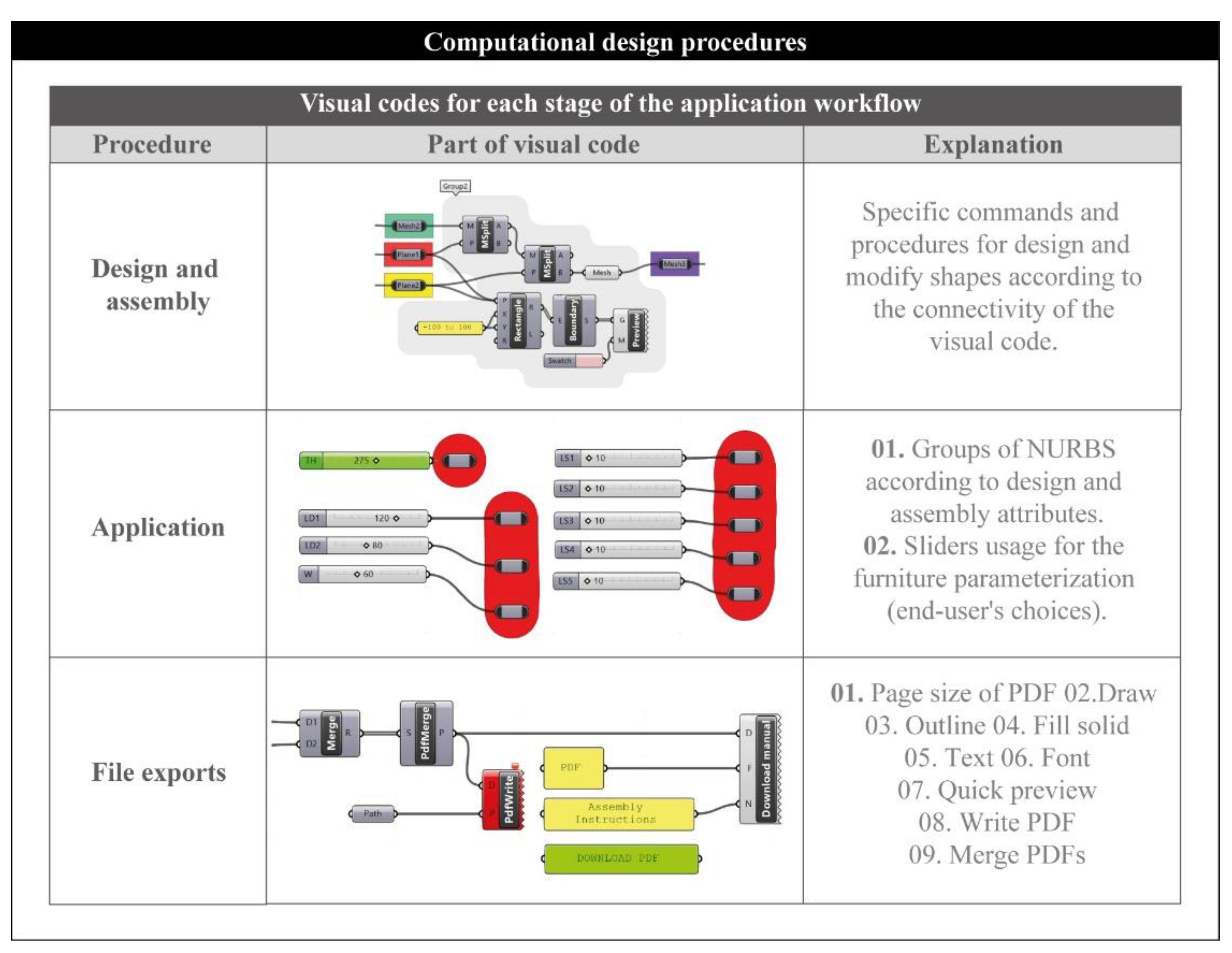
Figure 11 presents parts of the visual codes for each stage of the application workflow. More specifically, the whole code is divided into three programming areas: (a) design and assembly of the furniture, (b) application for the end-user’s design contribution and (c) export files. The first area of the graphical algorithm includes the necessary methods and properties for the design and assembly of the product’s morphology. At this stage, the designer is able to create the parts of furniture according to GrasshopperTM’s commands and procedures. Three kinds of parameters define the design procedure: the number of parts, type of parts and part specification.
Moreover, there are two more kinds of variables in the assembly definition: the types of connectivity and the technical requirements, such as total height. Following that, the designer groups the NURBS according to design and assembly attributes. More specifically, the designer uses special sliders with numerical values for the final furniture parameterization. The aforementioned sliders are connected to the parameters of the previous stage (number of parts, type of parts, part specification, etc.). It is important to note that the numerical values of the proposed parameters are made to be specific in order to protect the branded image of the prototype furniture.
The final code area is related to the procedure of exporting files. At this stage, the authors created nine operations for the final production of a PDF file that includes the assembly instructions. These significant operations deal with the (a) page size of the PDF (e.g., A4, A3, etc.), (b) visual representation of each furniture part, (c) outline creation based on wireframe models, (d) solid view of the whole object, (e) text and font specifications and finally (f) the merging of the produced pages. This means that the application automatically produces a full set of instructions and a product description for all the alternative designs requested by the user. The full automation of this procedure offers a significant cost reduction, while at the same time providing the final user with the ability to contribute towards the furniture design via choosing attributes of his preference.
The present case study shows an application for the automatic creation of a unique branded furniture with the aid of GrasshopperTM and Rhinoceros3DTM. Figure 12 illustrates an image of the desk workstation created based on the strong concept theme of DIY followed by the representation of two indicative desk design alternatives, which are based on the CbVBI methodology. The final desks are the result of a combination of a number of parameters.
Design alternative 1 includes the following values: TH = 250, LD1 = 120, WD1&2 = 80, LD2 = 150 and LS = 10. On the other hand, design alternative 2 is shaped by the values: 300, 200, 100, 150 and 50. Finally, according to the CbVBI methodology, a PDF manual with all the appropriate instructions for the furniture assembly is produced. The current manual is similar and looks like the instruction books found in IKEATM DIY products.
Finally, it is important to note the time saved with the use of the CbVBI methodology in comparison with traditional design procedures. More specifically, Figure 13 presents the final times of the two aforementioned case studies: (a) CAD-based design and assembly of a DIY coffee table and (b) graphical algorithmic design and assembly of a DIY desk workstation. More specifically, the time needed for the development of a coffee table design (first case study) using a traditional design method, SolidworksTM, is estimated to be about 85 min (including design and rendering procedures). On the other hand, the time needed for the development of the same coffee table via the use of CbVBI methodology was demonstrated to be 3.4 s. It is important to note that this time is relative to a computer’s sensitivity. The second case study involved the development of a workstation design. The time that a designer needs to develop a CAD model of a workstation with all design and assembly instructions via RhinoTM is estimated at about 270 min. The CbVBI methodology is capable of generating the same files (i.e., the CAD model and assembly instructions) in 8.2 s.

5. Conclusions

The present work deals with novel ideas for product development. The perception of the aforementioned CbVBI methodology deals with the parametrization of the visible elements of DIY design strategy (e.g., number of product parts, types of assembly, kinds of materials, etc.) according to a computational design approach. The core concept of the proposed design strategy is the automatic generation of furniture under the theme of DIY. The main contribution from the authors’ point of view is linked to the practical connection between the visual elements of branding identity and the design parameters according to automated and/or computational design approaches. The proposed case studies of the two different furniture pieces underline the digitalization of the aesthetic and ergonomic characteristics of the DIY design strategy. The authors suggest two different strategies for the implementation of the CbVBI methodology: (a) an application based on the textual script using SolidworksTM and VisualBasicTM and (b) an application based on graphical algorithmic design using Rhinoceros3DTM and GrasshopperTM.
The visual programming languages allow designers to build graphic-based programs rapidly, simply and flexibly. On the other hand, textual programming language (VBA) uses an event-driven approach to achieve the final outcome. Furthermore, textual languages follow three specific principles: primitive elements, combination mechanisms and abstraction mechanisms.
The result of these two different directions is an automated way to design a great number of furniture variations (coffee table and desk workspace) according to the end-users’ needs. The user becomes a design contributor via their participation in selecting the design parameters and thus strengthens the brand identity principles through product shape and morphology.

Author Contributions

Conceptualization, A.M. and P.K.; methodology, A.M. and P.K.; software, A.M., A.T. (Anastasios Tzotzis) and A.T. (Apostolos Tsagaris); validation, A.M., A.T. (Anastasios Tzotzis), A.T. (Apostolos Tsagaris) and P.K.; formal analysis, A.M., A.T. (Anastasios Tzotzis) and A.T. (Apostolos Tsagaris); investigation, A.M. and A.T. (Anastasios Tzotzis); resources, P.K.; data curation, A.M. and A.T. (Anastasios Tzotzis); writing—original draft preparation, A.M. and P.K.; writing—review and editing, A.M., A.T. (Anastasios Tzotzis), A.T. (Apostolos Tsagaris) and P.K.; visualization, A.M. and A.T. (Anastasios Tzotzis); supervision, P.K.; project administration, A.M. and P.K.; funding acquisition, P.K. All authors have read and agreed to the published version of the manuscript.

Funding

This research received no external funding.

Institutional Review Board Statement

Not applicable.

Informed Consent Statement

Not applicable.

Data Availability Statement

Not applicable.

Conflicts of Interest

The authors declare no conflict of interest.

References

  1. Neto, P.; Mendes, N.; Arajo, R.; Pires, J.N.; Moreira, A.P. High-level robot programming based on CAD: Dealing with unpredictable environments. Ind. Rob. 2012, 39, 294–303. [Google Scholar] [CrossRef] [Green Version]
  2. Tapoglou, N.; Antoniadis, A. 3-Dimensional kinematics simulation of face milling. Meas. J. Int. Meas. Confed. 2012, 45, 1396–1405. [Google Scholar] [CrossRef]
  3. Tzotzis, A.; Manavis, A.; Efkolidis, N.; Kyratsis, P. Cad-based automated g-code generation for drilling operations. Int. J. Mod. Manuf. Technol. 2021, 13, 177–184. [Google Scholar] [CrossRef]
  4. Kyratsis, P.; Tapoglou, N.; Bilalis, N.; Antoniadis, A. Thrust force prediction of twist drill tools using a 3D CAD system application programming interface. Int. J. Mach. Mach. Mater. 2011, 10, 18–33. [Google Scholar] [CrossRef] [Green Version]
  5. Gella-Marín, R.; Tzotzis, A.; García-Hernández, C.; Huertas-Talon, J.L.; Kyratsis, P. CAD software integration with programming tools for modelling, measurement and verification of surfaces. In Experiments and Simulations in Advanced Manufacturing; Kyratsis, P., Davim, J.P., Eds.; Springer: Berlin/Heidelberg, Germany, 2021; pp. 91–116. [Google Scholar]
  6. García-Hernández, C.; Gella-Marín, R.; Huertas-Talón, J.L.; Berges-Muro, L. Algorithm for measuring gears implemented with general-purpose spreadsheet software. Meas. J. Int. Meas. Confed. 2016, 85, 1–12. [Google Scholar] [CrossRef]
  7. Tzotzis, A.; Garcia-Hernandez, C.; Huertas-Talon, J.L.; Tzetzis, D.; Kyratsis, P. Engineering applications using CAD based application programming interface. MATEC Web Conf. 2017, 94, 01011. [Google Scholar] [CrossRef] [Green Version]
  8. Kyratsis, P.; Tzotzis, A.; Tzetzis, D.; Sapidis, N. Pneumatic cylinder design using cad-based programming. Acad. J. Manuf. Eng. 2018, 16, 107–113. [Google Scholar]
  9. Xiao, H.; Li, Y.; Yu, J.F.; Cheng, H. Dynamic assembly simplification for virtual assembly process of complex product. Assem. Autom. 2014, 34, 1–15. [Google Scholar] [CrossRef]
  10. Kyratsis, P.; Gabis, E.; Tzotzis, A.; Tzetzis, D.; Kakoulis, K. CAD based product design: A case study. Int. J. Mod. Manuf. Technol. 2019, 11, 110–115. [Google Scholar]
  11. Tzotzis, A.; García-Hernández, C.; Huertas-Talón, J.L.; Kyratsis, P. Cad-based automated design of fea-ready cutting tools. J. Manuf. Mater. Process. 2020, 4, 104. [Google Scholar] [CrossRef]
  12. Vijayaraghavan, A.; Dornfeld, D.A. Automated drill modeling for drilling process simulation. J. Comput. Inf. Sci. Eng. 2007, 7, 276–282. [Google Scholar] [CrossRef] [Green Version]
  13. Chun, D.M.; Kim, H.J.; Lee, J.C.; Ahn, S.H. Web-Based Material Database for Material Selection and Its Application Programming Interface (API) for CAD. Key Eng. Mater. 2007, 345–346, 1593–1596. [Google Scholar] [CrossRef]
  14. E Costa, E.C.; Jorge, J.; Duarte, J. Comparing digital tools for implementing a generative system for the design of customized tableware. Comput. Aided Des. Appl. 2019, 16, 803–821. [Google Scholar] [CrossRef]
  15. Manavis, A.; Kyratsis, P. A computational study on product shape generation to support brand identity. Int. J. Mod. Manuf. Technol. 2021, 13, 115–122. [Google Scholar]
  16. Kyratsis, P.; Manavis, A.; Gianniotis, P.; Ghiculescu, D. A non-conventional methodology for interior product design using conceptual design principles and parametric tools. Nonconv. Technol. Rev. Tehnol. Neconv. 2019, 23, 16–22. [Google Scholar]
  17. Garcia, S.; Menezes Leitão, A. Shape grammars as design tools: An implementation of a multipurpose chair grammar. Artif. Intell. Eng. Des. Anal. Manuf. AIEDAM 2018, 32, 240–255. [Google Scholar] [CrossRef]
  18. Khan, S.; Awan, M.J. A generative design technique for exploring shape variations. Adv. Eng. Inform. 2018, 38, 712–724. [Google Scholar] [CrossRef] [Green Version]
  19. Hatton-Jones, S.; Teah, M. Case analysis of the do-it-yourself industry. Asia Pac. J. Mark. Logist. 2015, 27, 826–838. [Google Scholar] [CrossRef]
  20. Kyratsis, P.; Tzotzis, A.; Manavis, A. Computational design and digital fabrication. In Advances in Manufacturing Systems; Kumar, S., Rajurkar, K.P., Eds.; Springer: Singapore, 2021; pp. 1–17. [Google Scholar]
  21. Mengoni, M.; Peruzzini, M.; Raffaeli, R.; Raponi, D. A Web-based Platform to Support Contract Furniture Design. Comput. Aided Des. Appl. 2014, 11, 533–543. [Google Scholar] [CrossRef]
  22. Bernal, M.; Haymaker, J.R.; Eastman, C. On the role of computational support for designers in action. Des. Stud. 2015, 41, 163–182. [Google Scholar] [CrossRef]
Figure 1. Computational-based Visual Brand Identity design methodology for the furniture industry.
Machines 10 01065 g001
Figure 2. The three tabs of the coffee table design application.
Machines 10 01065 g002
Figure 3. Workflow of the coffee table design application.
Machines 10 01065 g003
Figure 4. API methods and properties used for the design procedure.
Machines 10 01065 g004
Figure 5. API methods and properties used for the assembly procedure.
Machines 10 01065 g005
Figure 6. API methods and properties used for the rendering and the property export procedures.
Machines 10 01065 g006
Figure 7. Code sample and algorithm flowchart used.
Machines 10 01065 g007
Figure 8. Desk workstation design application as created with Shape DiverTM.
Machines 10 01065 g008
Figure 9. Workflow of the desk workstation design application.
Machines 10 01065 g009
Figure 10. Implementation tools based on computational design techniques.
Machines 10 01065 g010
Figure 11. Computational design procedures.
Machines 10 01065 g011
Figure 12. Desk workstation design alternatives and export files.
Machines 10 01065 g012
Figure 13. CbVBI time savings.
Machines 10 01065 g013
Publisher’s Note: MDPI stays neutral with regard to jurisdictional claims in published maps and institutional affiliations.

