Communication

Development of Harmonic Drive Combining Four Arcs for Conventional Kinematic Application

Mechanical Engineering Department, Chung-Ang University, Seoul 06974, Korea
*
Author to whom correspondence should be addressed.
Machines 2022, 10(11), 1058; https://doi.org/10.3390/machines10111058
Submission received: 10 October 2022 / Revised: 3 November 2022 / Accepted: 4 November 2022 / Published: 10 November 2022
(This article belongs to the Section Machine Design and Theory)

Abstract

:
This paper proposes a modified harmonic cam, which is used to design a harmonic drive. Conventional harmonic drives using a sinusoidal cam type pertain to an elastic body concept and are thus difficult to design and evaluate. Unlike the conventional sinusoidal cam, the proposed harmonic cam involves a combination of four arcs. Such cams can be designed based on a rigid body concept, and thus, the tooth profile can be designed and analyzed using the established gear theory. The novel harmonic cam is designed by exploiting four-arc combinations, and guides for designing harmonic drives with involute and cycloid angular teeth are presented. A harmonic drive with a difference of two teeth between the circular spline and flex spline is designed. The operation, tooth engagement, and interference are validated through a mock-up production using a 3D printer and gear simulation program. The findings can facilitate the facile design and manufacturing of harmonic drives.

1. Introduction

Harmonic drives were first developed by Muser to increase torque by decreasing the rotational speed of a motor as the power source. Such frameworks were initially termed “strain wave gearing systems” [1,2,3], and the term “harmonic drive” was coined later [4]. A harmonic reducer has a simple structure with three components: a wave generator, flex spline, and circular spline. Such systems have a small size, low weight, high reduction gear ratio, and high efficiency, and are thus widely used in various industries such as robotics, military applications, aerospace applications, precision positioning systems, and semiconductor manufacturing, for instance, in humanoid robots and computer numerical control machine tools [5,6,7].
However, the existing gear theory cannot be applied to harmonic reducers because the elastic theory is applied to these reducers, whereas the rigid body theory is applied to the other reducers [5,6,7,8]. Consequently, if the shape of the harmonic reducer is changed, the tooth profile must be modified considering the tooth trajectory that depends on the change in the tooth center [9]. Moreover, because the circumferential length of the existing sinusoidal cam is challenging to compute and is typically determined by approximation, the arrangement of teeth and their analysis are challenging.
Various studies have been conducted to solve the problem of harmonic drive. Many researchers have attempted to solve these problems by analyzing the kinetic characteristics of harmonic drives and have focused on tooth profile design. Muser studied the kinetic characteristics of harmonic drives [1,2,3]. Ishikawa studied the tooth profile of the harmonic drives in a more generalized state than that considered by Muser, and applied a simplified analytical formula for tooth engagement [10]. Ishikawa introduced a point-symmetrical curve as a tooth profile of harmonic drives in order to improve the engagement properties and fatigue life [11]. Kiyosawa attempted to improve the fatigue strength and rigidity in the low torque region by using a tooth profile consisting of convex and concave curves at the end and root, respectively [12]. Kayabasi calculated the stress on flex spline teeth and optimized the tooth profile of a flex spline through finite element method (FEM) analyses to maximize the fatigue life [5]. Xin simplified the profile of the gear tooth of a flex spline as two simple shapes, a rectangle and trapezoid, and compared the effect of these [13]. Chen proposed a method for designing the tooth profile for dual disc cam and for performing backlash assessments for a harmonic drive to enable more teeth to participate in engagement, and analyzed the influence of the tooth profile [14]. Dong developed a method describing the spatial elastic deformation function of a cup-type flex spline and discussed the elastic deformation characteristics, which provided a basis for the kinematic analysis of harmonic drives [15]. Sahoo et al. modified the involute tooth profile to avoid tooth interference, and estimated the load distribution in the contact section by deriving the tooth stiffness [16]. Song et al. proposed a design method of double-circular-arc tooth profile based on curve mapping and bidirectional conjugation, and they designed a tooth profile and analyzed the influence of the design parameters on the tooth profile shape and characteristics [17]. These studies were considered within the concept of elasticity, with a suitable tooth shape being required for each specification of the harmonic drives.
Moreover, several studies have focused on material selection, and wave generator designs have been conducted. Wang developed a model to enhance the stress distribution and reduce the maximum stress applied to the flex spline by applying a solid filler to the nonworking area of the cam according to the deflection curve of the flex spline [18]. Jeon and Oh investigated the vibration characteristics of flex splines composed of two materials: steel and steel–composite hybrid flex splines using carbon-fiber epoxy and glass-fiber epoxy composite materials [7]. The selection of material does not solve the structural problem. Maiti developed a new cam based on the existing involute tooth profile using two circles and elliptical curves, however, there are still difficulties in tooth arrangement and analysis due to errors in the circumference length calculation [8]. Gravagno formulated kinematic errors for various wave generator shapes, however, this study is considered within the concept of elasticity and cannot use the gear of the conventional rigid body concept [19]. Li et al. optimized a model of wave generator profile and object function in order to minimize the maximum circumferential stress of the flex spline assembled with the wave generator, however, this profile has limitations due to being modified based on the existing sine cam [20].
Mahanto performed FEM analyses to study the stress and deformation of a flex spline introduced due to the insertion of wave generators through FEM analysis [21]. Jia analyzed the pure kinematic errors in a harmonic drive with machining and assembly errors, and presented a novel wave generator configuration that could enhance the transmission performance of the drive [22].
This paper proposes a novel harmonic cam that is used to design wave generators and flex and circular splines. The reducer is designed according to a rigid concept. Consequently, the tooth trajectory does not change, owing to the lack of variation in the center of the tooth, and the framework can be analyzed and manufactured more easily than the existing harmonic drive based on an elastic concept. In addition, because the circumferential length is defined using a simple equation and not approximated as in conventional sinusoidal cams, the arrangement of teeth is facilitated. Both internal and external gears can be designed using the existing involute profile, and the durability can be increased by applying a cycloid gear to reduce the stress concentration at the base of the teeth that typically occurs during the flex spline deformation process [23].
Section 2 and Section 3 describe the four-arc combination cam that is used to design a harmonic reducer for each tooth type. Section 4 describes the simulations performed to verify the tooth engagement and interference. Section 5 presents the design and mock-up products for checking the tooth engagement and drive. Section 6 presents the concluding remarks.

2. Harmonic Cam Using Four-Arc Combination

This section describes the proposed harmonic cam based on a four-arc combination.

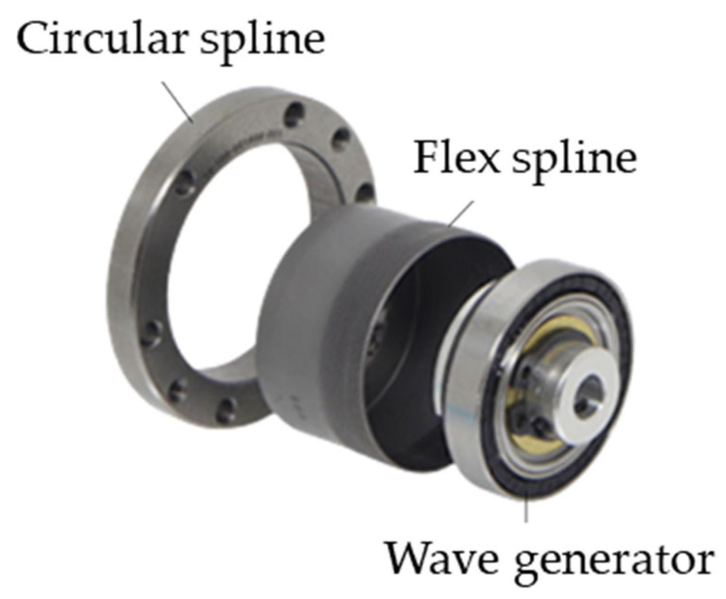
2.1. Kinetic Characteristics of Harmonic Drives

Harmonic drives consist of wave generators, flex splines, and circular splines [5] (Figure 1). A wave generator, which consists of a narrow ball-bearing assembled on an elliptical cam outer ring, converts spiral rotation motion to power in a wave rotation form. Circular splines are metal internal gear components that have two or four more teeth compared with flex splines. Flex splines are metallic, thin cup-shaped components that are deformed by the wave-rotating motion of the wave generator and transmit torque in contact with the circular splines at the elliptical long axis point [5,22].
The conventional harmonic cam equation is represented by the coordinates of the points on the corresponding flex spline line, when circular splines with diameter d c are fixed and the wave generator rotates (Figure 2):
r ( θ ) = d f 2 + δ 2 cos 2 θ
d c = Z c Z f d f = i d f
where ( i = Z c Z f ) , i > 1 .
δ = d f ( λ Z c Z f 1 ) = d f ( λ i 1 )
where d f   is the diameter of the flex spline before deformation, δ is the elastic deformation of the flex spline, Z c and Z f are the numbers of lobes on the circular and flex splines, respectively, i is the ratio of Z c to Z f , and λ is the deviation coefficient.
The deviation coefficient ( λ ) can be obtained through Equation (3) as a variable representing the kinetic characteristics of the harmonic drive.
λ = 1 i ( 1 + δ d f )
The deviation coefficient typically ranges from 0.98 to 1.02, and indicates the amount of engagement elastic deformation of the tooth shape. The standard value is 1. When the value is smaller than 1, the elastic displacement and bending stress reduce, and the strength of wave generators and flex splines is enhanced. However, the depth of motion decreases, and the interference, noise, and vibration levels increase. When the value is greater than 1, the elastic displacement increases, which increases the depth of motion and decreases the noise and vibration levels. However, the bending stress increases, and strength reduces [23].
When using the existing harmonic equation represented by Equation (1), it is difficult to apply conventional gear theory because the center of each tooth changes continuously [9]. In addition, an error occurs because the integral line is calculated as an approximate equation when calculating the circumferential length, and the method of arranging gears vertically on the neutral line is also very complicated.

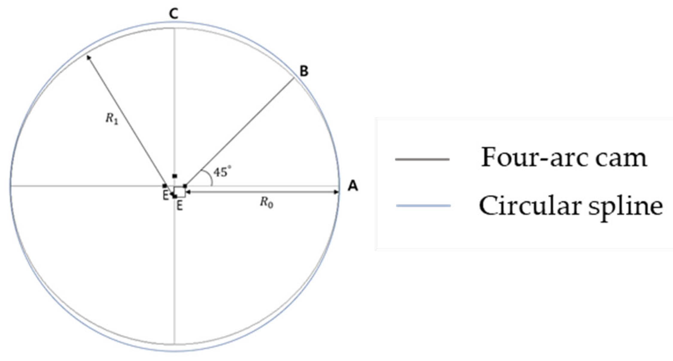
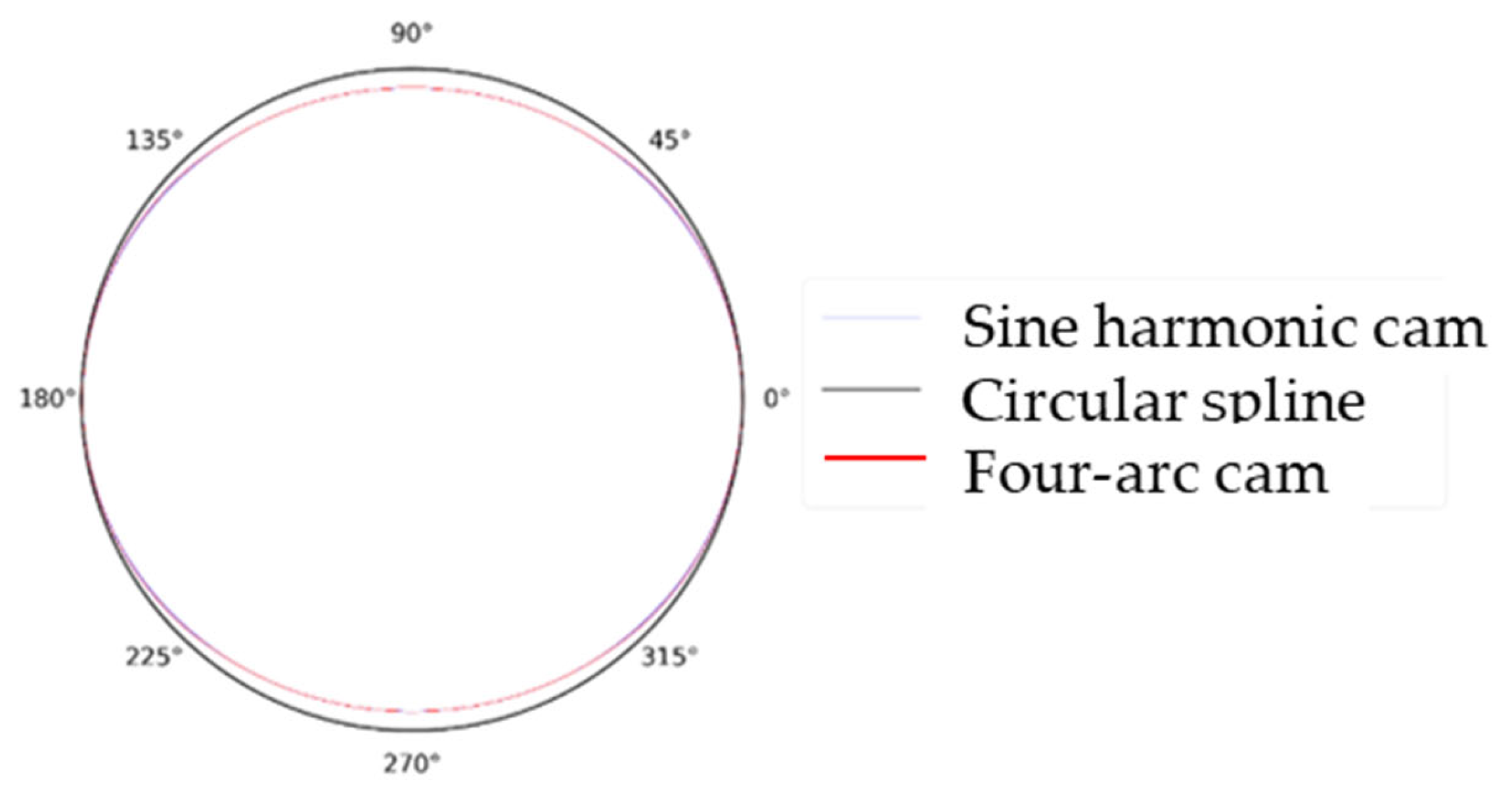
2.2. Four-Arc Combination Cam

We introduce a four-arc combination cam to alleviate the limitations of the existing sinusoidal harmonic cam (Equation (1)) and apply the existing gear theory. Sections AB and BC are arcs having radii R 0 and R 1 , respectively (Figure 3). For design convenience, the angle is arbitrarily set as θ = 45 ° .
R 1 can be defined as
R 1 = R 0 + 1 cos θ E = R 0 + 2 E
where E is the eccentricity.
The long- and short-axis radii are defined as follows:
Long - axis   radius   d f 2 + δ 2 = R 0 + E
Short - axis   radius   d f 2 δ 2 = R 0 + 2 E E
By subtracting Equation (6) from Equation (7) and substituting Equation (3), the following expression can be obtained:
E = δ 2 2 = d f 2 2 ( λ i 1 )
Adding Equations (6) and (7) and substituting Equation (8) yields
R 0 = d f 2 2 2 E = d f 2 2 δ 2 ( 2 2 ) = d f 2 - 2 d f 2 ( 2 2 ) ( λ i 1 )
In Equations (8) and (9), E and   R 0 depend on λ . Therefore, the neutral line of the flex spline can be designed by selecting E and   R 0 by appropriately adjusting λ .
It is assumed that the circumferential length of the flex spline is identical before and after deformation [15]. Therefore, the following expression must be satisfied:
π R = π ( R 0 + R 1 )
Substituting Equations (5), (8) and (9) into Equation (10) yields
R = R 0 + 2 2 E = d f 2
In other words, the circumferential length of the four-arc combination cam is always constant regardless of λ . In the case of the harmonic equation, errors due to approximation are generated when the shape is converted to the corresponding circle by circumferential integration. For example, when the shape transforms to a circle of d f = 56.0 mm in the context of the sinusoidal cam in Equation (1), d f ' is 56.0126 mm. Such errors make it difficult to arrange the teeth. In contrast, when the four-arc combination cam is used, because the circumferential length after deformation can be simply and accurately calculated, the teeth can be arranged more easily compared with the conventional harmonic cam. Moreover, when designing the harmonic drives, the teeth should be arranged vertically to the neutral line. Since the proposed cam is composed of arcs, teeth can be easily arranged. Also, because the center of the teeth is constant in the contact section, conventional gear theory can be used (Figure 4).
Figure 5 compares the sinusoidal harmonic cam and four-arc combination cam curves, and indicates that they are nearly identical.

3. Harmonic Drive Design Guide

We designed a harmonic drive with rigid kinematics using involute and cycloid gears. The designed teeth are applied to the extended part of the long axis, and the teeth in the long axis are simply arranged in the noncontact section. Because the teeth in the neutral line must be equidistant, the following expressions must hold.
R 0 p t = R 1 p 1
R 0 p t = R p f
R 1 p 1 = R p f
p f = 2 π Z f
p t = 2 π Z t
p 1 = 2 π Z 1
where p t is the angle between the teeth in arc AB, p 1 is the angle between the teeth in arc BC, and p f is the angle between the teeth in the flex spline before deformation.
The equivalent numbers of teeth Z t can be obtained by substituting Equations (15) and (16) into Equation (13).
Z t = Z f ( 3.414 2.414 λ i )

3.1. Proposed Guide for Harmonic Drive Design with Cycloid Gear

First, design the tooth with contact with two cycle gears with circular and flex splines that have radii R c and R 0 + h , respectively, and numbers of lobes z c and z t , respectively.
1.
Define the number ratio of lobes of the flex and circular splines, i = Z c Z f
2.
Define λ
Calculate the equivalent number of teeth Z t in Equation (18)
3.
Define the neutral line diameter d f and offset = h
Calculate R 0 in Equation (9)
Calculate the equivalent module in Equation (19)
m t = 2 ( R 0 + h ) Z t  
Second, place the teeth designed in step 1 onto the neutral line.
(1)
Arc AB: Arrange m t teeth into the circumferential pitch p t
(2)
Arc BC: Arrange m t teeth into the circumferential pitch p 1
If the teeth overlap in section B (Figure 6), arrange the teeth using Equation (20).
θ 1 = p 1 ( 1 θ t p t )
where θ t is the angle up to the last tooth arrangement of the B-point reference arc AB, and θ 1 is the starting angle of the arrangement of arc BC based on point B.
Third, design the circular spline with number of lobes Z c and module m t .
Figure 7 illustrates the process of designing a harmonic drive with the desired reduction gear ratio and size.

3.2. Proposed Guide for Harmonic Drive Design with Involute Gear

First, perform tooth design with contact of two cycle gears with circular and flex splines that have radii R c and R 0 + h , respectively, and numbers of lobes z c and z t , respectively.
(1)
Define the number ratio of lobes of the flex and circular splines, i = Z c Z f
(2)
Define λ
Calculate the equivalent number of teeth Z t in Equation (18)
(3)
Define neutral line diameter d f and offset = h
Calculate R 0 in Equation (9)
Calculate equivalent module in Equation (19)
(4)
Adjust the involute gear
The internal gear equation is
i n v α b = 2 tan α x 1 + x 2 z 1 + z 2 + i n v α c
where α c   is the tool pressure angle, α b is the engagement pressure angle, x 1 , x 2 are the profile shift coefficients, and z 1 , z 2 are the number of lobes
E = z 2 z 1 2 m + z 2 z 1 2 m ( cos α c cos α b 1 )
where E is the eccentricity.
If the profile shifted gear is not used, E becomes
E = z 2 z 1 2 m
According to the harmonic drive design guide with the cycloid gear, E is
E = R c ( R 0 + h )
E = m t z c 2 m t z t 2  
In other words, E defined in Section 3.1 can be used as is. When designing a harmonic drive with an involute gear, the gear width can be adjusted through a profile shift coefficient. In the internal gear equation, if the profile shift coefficient of the two gears is the same, the engagement pressure angle is the same, and the eccentricity does not change.
The subsequent process is the same as that of the design based on the cycloid gear.

4. Gear Design

For subsequent analysis, gears with the following characteristics are designed (Table 1): flex spline diameter before deformation d f = 100   mm ; number of lobes z c = 74 , z f = 72 ; deviation coefficient λ = 0.99 ; and offset h = 1   mm . A Python-based simulation program is used to clarify the gear engagement and interference. The results indicate no problems associated with the engagement or interference (Figure 8).

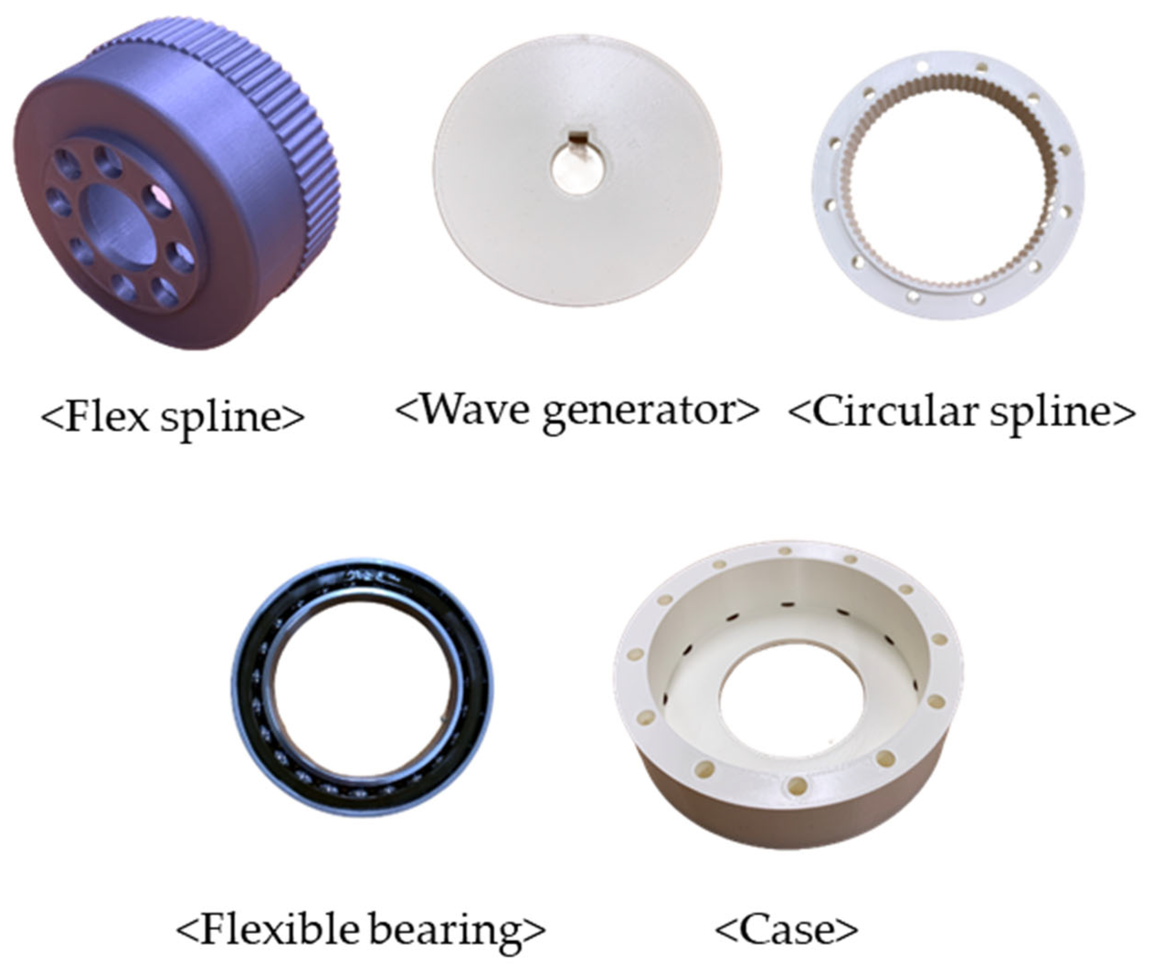
5. Design of Harmonic Drive

The design guide presented in the previous section is used to design a harmonic drive. In general, interference can be prevented by increasing the pressure angle of the involute gear or by lowering the addendum and dedendum in planocentric reducers designed with involute gears [24]. Notably, as the pressure angle increases, the noise increases and the contact rate decreases [24]. Moreover, when the flex spline is deformed, stress is concentrated on the bottom of the involute tooth shape. Accordingly, by setting λ as 0.99, cycloid gears were applied to lower the bending stress and alleviate the problems associated with interference and noise. Figure 9 shows the mock-up model components manufactured using a 3D printer. The operation and tooth engagement of the designed harmonic drive are verified through the manufactured models (Figure 10).

6. Conclusions

This paper proposes a wave generator design method using a new harmonic cam formula; and design guides for flex and circular splines using cycloid and involute gears are presented. The harmonic cam consists of a combination of four arcs, which facilitates the design process. In addition, unlike the existing harmonic cams, such as the sinusoidal cams and dual disc cam that are represented by functions that cannot be integrated when calculating the circumferential length, the cam is represented correctly by a simple equation. Consequently, the circumferential length calculation and teeth arrangement can be easily and accurately performed. In addition, because the center of the gear does not change in the section in which the teeth are in contact, conventional gear theory can be applied. Based on the design guides, a harmonic drive using cycloid and involute gears with a 34:1 reduction gear ratio is manufactured. The tooth engagement and interference are evaluated through a simulation program and mock-up production.
The proposed harmonic cam overcomes the limitations of the existing sinusoidal cam and other cams. The design and manufacturing process of the harmonic drive can be simplified by applying the existing involute and cycloid tooth types. Additionally, the conventional kinematics can be applied, rendering it possible to apply various mathematical models for performance evaluation.
Future work can be aimed at establishing a mathematical model and a performance evaluation instrument for evaluating harmonic drives with involute and cycloid tooth profiles. In this study, the length of the neutral line and tooth deformation are assumed to be constant. These assumptions must be validated in future studies.

Author Contributions

Conceptualization, T.K.; methodology, T.K.; software, S.O.; investigation, H.J.; data curation, J.L.; writing—original draft preparation, T.K.; writing—review and editing, T.K.; supervision, S.O.; project administration, W.J. All authors have read and agreed to the published version of the manuscript.

Funding

This work supported by the Technology Innovation Program (20001184, Development of ultrathin and short precision reducers and high torquetoweight ratio precision reducers for HRC robots) funded By the Ministry of Trade, Industry & Energy (MOTIE, Korea).

Institutional Review Board Statement

Not applicable.

Informed Consent Statement

Not applicable.

Data Availability Statement

Not applicable.

Acknowledgments

This research was supported by the Chung-Ang University research grant in 2021.

Conflicts of Interest

The authors declare no conflict of interest.

References

  1. Musser, C.W. Strain Wave Gearing. U.S. Patent No. 2.906, 1959. [Google Scholar]
  2. Musser, C.W. Spline and Rotary Table. U.S. Patent No. 2,959,065, 1960. [Google Scholar]
  3. Musser, C.W. The harmonic drive. Mach. Des. 1960, 14, 160–173. [Google Scholar]
  4. Brighton, D.K. Harmonic Drives. U.S. Patent No. 3,996,816, 1976. [Google Scholar]
  5. Kayabasi, O.; Fehmi, E. Shape optimization of tooth profile of a flexspline for a harmonic drive by finite element modelling. Mater. Des. 2007, 28, 441–447. [Google Scholar] [CrossRef]
  6. Chen, X.; Liu, Y.; Xing, J.; Lin, S.; Ma, M. A novel method based on mechanical analysis for the stretch of the neutral line of the flexspline cup of a harmonic drive. Mech. Mach. Theory 2014, 76, 1–19. [Google Scholar] [CrossRef]
  7. Jeon, H.S.; Oh, S.H. A study on stress and vibration analysis of a steel and hybrid flexspline for harmonic drive. Compos. Struct. 1999, 47, 827–833. [Google Scholar] [CrossRef]
  8. Maiti, R. A Novel Harmonic Drive With Pure Involute Tooth Gear Pair. J. Mech. Des. 2004, 126, 178–182. [Google Scholar] [CrossRef]
  9. Bamnote, A.J.; Mahale, P.; Gulhane, R. Meshing Analysis of Teeth of Harmonic Drives: A Computer Based Approach; Dept. of Mechanical Engg., YC College of Engg.: Nagpur, India, 2000; pp. 1–8. [Google Scholar]
  10. Ishikawa, S. The gear geometry of tooth engagement in harmonic drive. Proceedings of [the JSME] 1967 Semi-international Symposium; 1967. [Google Scholar]
  11. Ishikawa, S. Tooth Profile of Spline of Strain Wave Gearing. U.S. Patent No. 4,823,638, 1989. [Google Scholar]
  12. Kiyosawa, Y. Performance of a strain wave gearing using a new tooth profile. In ASME International Power Transmission and Gearing Conference; American Society of Mechanical Engineers: New York, NY, USA, 1989; Volume 11, p. 607. [Google Scholar]
  13. Xin, H.B.; Mo, H.N.; Gao, J.C.; Wang, W.J.; Cui, D.Q.; Liu, L.; Wang, T.; Xin, Y.F. Study on the Gear Tooth Influence Coefficients of Flexspline of Harmonic Drive. Adv. Mater. Res. 2013, 774–776, 144–147. [Google Scholar] [CrossRef]
  14. Chen, X.; Liu, Y.; Xing, J.; Lin, S.; Xu, W. The parametric design of double-circular-arc tooth profile and its influence on the functional backlash of harmonic drive. Mech. Mach. Theory 2014, 73, 1–24. [Google Scholar] [CrossRef]
  15. Dong, H.; Ting, K.-L.; Wang, D. Kinematic Fundamentals of Planar Harmonic Drives. J. Mech. Des. 2011, 133, 011007. [Google Scholar] [CrossRef]
  16. Sahoo, V.; Maiti, R. Load sharing by tooth pairs in involute toothed harmonic drive with conventional wave generator cam. Meccanica 2018, 53, 373–394. [Google Scholar] [CrossRef]
  17. Song, C.; Li, X.; Yang, Y.; Sun, J. Parameter design of double-circular-arc tooth profile and its influence on meshing characteristics of harmonic drive. Mech. Mach. Theory 2021, 167, 104567. [Google Scholar] [CrossRef]
  18. Wang, S.; Li, D.; Mao, S.; Chen, B. Design and Analysis of Cam Wave Generator Based on Free Deformation in Non-Working Area of the Flexspline. Appl. Sci. 2021, 11, 6049. [Google Scholar] [CrossRef]
  19. Gravagno, F.; Mucino, V.H.; Pennestrì, E. Influence of wave generator profile on the pure kinematic error and centrodes of harmonic drive. Mech. Mach. Theory 2016, 104, 100–117. [Google Scholar] [CrossRef]
  20. Li, X.; Song, C.; Yang, Y.; Zhu, C.; Liao, D. Optimal design of wave generator profile for harmonic gear drive using support function. Mech. Mach. Theory 2020, 152, 103941. [Google Scholar] [CrossRef]
  21. Mahanto, B.S.; Sahoo, V.; Maiti, R. Effect of Cam Insertion on Stresses in Harmonic Drive in Industrial Robotic Joints. Procedia Comput. Sci. 2018, 133, 432–439. [Google Scholar] [CrossRef]
  22. Jia, H.; Li, J.; Xiang, G.; Wang, J.; Xiao, K.; Han, Y. Modeling and analysis of pure kinematic error in harmonic drive. Mech. Mach. Theory 2020, 155, 104122. [Google Scholar] [CrossRef]
  23. Lee, C.W.; Oh, S.H.; Kim, J.C.; Jeon, H.S. Development of Harmonic Drive Using Cycloide Tooth Profile. Trans. Korean Soc. Mech. Eng. A 1997, 21, 1166–1173. [Google Scholar]
  24. Jang, D.-J.; Kim, Y.-C.; Hong, E.-P.; Kim, G.-S. Geometry design and dynamic analysis of a modified cycloid reducer with epitrochoid tooth profile. Mech. Mach. Theory 2021, 164, 104399. [Google Scholar] [CrossRef]
Figure 1. Harmonic Drive Components.
Machines 10 01058 g001
Figure 2. Sinusoidal harmonic cam curve.
Machines 10 01058 g002
Figure 3. Four-arc combination cam curve.
Machines 10 01058 g003
Figure 4. Center of the teeth of the designed flex spline.
Machines 10 01058 g004
Figure 5. Comparison of two types of cams.
Machines 10 01058 g005
Figure 6. Teeth in Section B.
Machines 10 01058 g006
Figure 7. Flowchart for designing a harmonic drive.
Machines 10 01058 g007
Figure 8. Program to check the gear engagement and interference: (a) Cycloid (b) Involute.
Machines 10 01058 g008
Figure 9. Mock-up model components.
Machines 10 01058 g009
Figure 10. Mock-up model to check (a) the gear engagement (b) the operation.
Machines 10 01058 g010
Table 1. Design parameters and results of harmonic gear.
Parameter Value
Input dataLobes of circular spline, Z c 74
Lobes of flex spline, Z f 72
Deviation coefficient, λ 0.99
Diameter of flex spline, d f (mm) 100
Offset distance, h (mm)1
ResultsRadii R 0 , R 0 (mm)47.8876
Radii R 1 , R 1 (mm)52.1124
Eccentricity distance, E (mm)2.9874
Module, m t 1.4179
Publisher’s Note: MDPI stays neutral with regard to jurisdictional claims in published maps and institutional affiliations.

